
9PX G2_3-11kVA_US_EN
Eaton 9PX G2
Advanced User Guide
Copyright © 2025 EATON
All rights reserved.
9PX3K3UG2
9PX5KG2
9PX6KG2
9PX6KIECG2
9PX8KG2
9PX11KG2
9PXEBM180RTG2
9PXEBM240RTG2
MBP6K208G2
MBP6KIECG2
MBP11K208G2

9PX G2_3-11kVA_US_EN
Table of Content
1
Special symbols and safety instructions
............................................................................ 4
2
Introduction
........................................................................................................................ 5
2.1
Environmental protection ........................................................................................................................ 5
2.2
Benefits .................................................................................................................................................... 6
3
Presentation
....................................................................................................................... 7
3.1
Weights and dimensions ........................................................................................................................... 7
3.2
Rear Panel ................................................................................................................................................ 8
3.3
Optional accessories ............................................................................................................................... 11
4
Installation
........................................................................................................................ 12
4.1
Inspecting the equipment....................................................................................................................... 12
4.2
Unpacking the UPS ................................................................................................................................. 15
4.3
Recommended positions ........................................................................................................................ 16
4.4
EBM connection ..................................................................................................................................... 19
4.5
UPS connection ...................................................................................................................................... 22
4.6
Register warranty ................................................................................................................................... 25
4.7
Connection with MBP ............................................................................................................................. 26
5
Interfaces and communication
........................................................................................ 36
5.1
Control panel.......................................................................................................................................... 36
5.2
LCD description ...................................................................................................................................... 37
5.3
Display functions .................................................................................................................................... 38
5.4
User settings .......................................................................................................................................... 39
5.5
Advanced Battery Management + .......................................................................................................... 43
5.6
Communication ports ............................................................................................................................. 43
5.7
UPS remote control functions ................................................................................................................. 46
5.8
Eaton Intelligent Power Software suite ................................................................................................... 48
5.9
Cybersecurity ......................................................................................................................................... 48
6
Operation
......................................................................................................................... 49
6.1
Start-up and normal operation ............................................................................................................... 49
6.2
Starting the UPS on battery .................................................................................................................... 49
6.3
UPS start-up with HotSwap MBP ............................................................................................................ 49
6.4
UPS shutdown ........................................................................................................................................ 50

9PX G2_3-11kVA_US_EN
6.5
Operating modes .................................................................................................................................... 50
6.6
Return of AC input power ....................................................................................................................... 51
6.7
Configuring battery settings ................................................................................................................... 51
6.8
Deep discharge protection ..................................................................................................................... 52
7
UPS maintenance
............................................................................................................. 53
7.1
Equipment care ...................................................................................................................................... 53
7.2
Storing the equipment ........................................................................................................................... 53
7.3
When to replace batteries ...................................................................................................................... 53
7.4
UPS replacement with HotSwap MBP ..................................................................................................... 54
7.5
UPS maintenance with HotSwap MBP .................................................................................................... 57
7.6
Recycling the used equipment ................................................................................................................ 57
8
Troubleshooting
............................................................................................................... 58
8.1
Typical alarms and faults ........................................................................................................................ 58
8.2
Silencing the alarm ................................................................................................................................. 59
8.3
Service and support ................................................................................................................................ 59
9
Specification and technical characteristics
..................................................................... 60
9.1
UPS model list ........................................................................................................................................ 60
9.2
Extended Battery Module model list ...................................................................................................... 60
9.3
Electrical input ....................................................................................................................................... 60
9.4
Electrical input connections .................................................................................................................... 61
9.5
Electrical output ..................................................................................................................................... 62
9.6
Electrical output connection ................................................................................................................... 62
9.7
Electrical Output Power .......................................................................................................................... 63
9.8
Battery ................................................................................................................................................... 63
9.9
Battery Backup time ............................................................................................................................... 64
9.10
Environmental and safety ....................................................................................................................... 67
1
Glossary
............................................................................................................................ 68

1
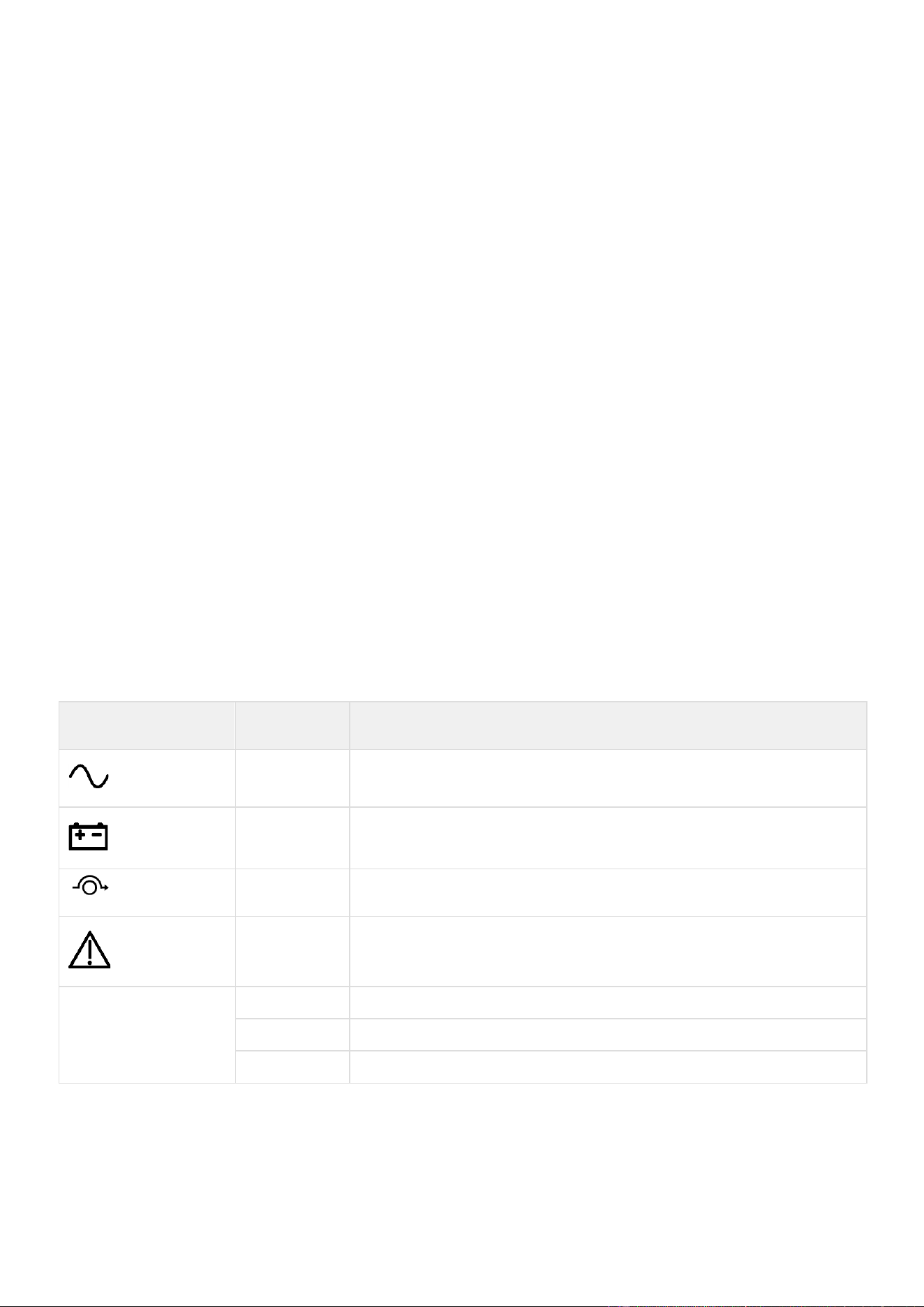
Special symbols and safety instructions
Special symbols
The following are examples of symbols used on the UPS or accessories to alert you to important information:
DANGER:
Dangerous voltage levels are present within the UPS. The UPS has its
own
internal power source (the battery). Consequently, the power outlets may be
energized
even if the UPS is disconnected from the AC power source.
Important instructions that must always be followed.
CAUTION: Batteries present a risk of energy or electrical shock or burn from high
short
circuit current. Observe proper precaution. Batteries may contain HIGH VOLTAGE and
CORROSIVE, TOXIC and EXPLOSIVE substances.
Information, advice, help.
Read the documentation provided.
Disconnect input plug.
Before maintenance, first shut down the UPS then disconnect the AC power source,
internal and external batteries then discharge capacitors by pressing the ON button
and wait 5 minutes.
This equipment should only be used in a dry indoor environment. Operating range of
temperature.
Operating range of humidity.
The UPS and their batteries must be kept in a ventilated place.
USB Communication Port
Alternating Curent (AC) Direct Curent (DC)

2
Introduction
Thank you for selecting an Eaton 9PX G2 product to protect your electrical equipment.
The Eaton 9PX G2 range has been designed with the utmost care. We recommend that you take the time to read this advanced
user guide to take full advantage of the many features of your UPS (Uninterruptible Power System).
Before installing your Eaton 9PX G2, please read the information and safety instructions provided. Follow the instructions in the
quick start guide and if necessary, refer to this advance user guide.
To discover the entire range of Eaton products, we invite you to visit our web site at eaton.com or
contact your Eaton local
representative.
WARNING:
• This is a category C2 UPS product. In a residential environment, this product may cause radio interference, in which case
the user may be required to take additional measures.
• Disconnection and overcurrent protection devices shall be provided by others for permanently connected AC input (
Normal AC/Bypass AC)/output circuits
NOTE: This equipment has been tested and found to comply with the limits for a Class A digital device, pursuant to Part 15 of
the FCC Rules. These limits are designed to provide reasonable protection against harmful interference when the equipment
is operated in a commercial environment. This equipment generates, uses, and can radiate radio frequency energy and, if
not installed and used in accordance with the instruction manual, may cause harmful interference to radio communications.
Operation of this equipment in a residential area is likely to cause harmful interference in which case the user will be
required to correct the interference at his own expense
.
UPS employing batteries with HB case are intended not for use in a computer room as defined in the standard for the Protection of
Information Technology Equipment, ANSI/NFPA 75.
Supplier's Declaration of Conformity of Federal Communications Commission Statement
This device complies with Part 15 of the FCC Rules. Operation is subject to the following two conditions:
(1)
this device may not cause harmful interference, and
(2)
this device must accept any interference received, including interference that may cause undesired operation.
For
questions regarding this FCC SDoC declaration, contact Eaton Corporation by telephone or through the Internet.
Eaton Corporation 1000 Eaton Blvd,
Cleveland, OH 44122, USA
Telephone: (440) 523-5000
2.1
Environmental protection
Eaton has implemented an environmental-protection policy. Products are developed according to an eco-design
approach.
Substances
This product contains no CFC, HCFC or asbestos. This product is compliant with regulations on the restriction of the use of
substances in electrical and electronic equipment.
Packaging
To improve waste treatment and facilitate recycling, separate the various packing components.
•
Packing materials are recyclable and bear the appropriate identification symbol.
•
The cardboard we use comprises over 50% of recycled cardboard.
•
Plastic bags are made of polyethylene.

Materials
Abbreviations
Number in the symbols
Polyethylene terephthalate
PET
01
High-density polyethylene
HDPE
02
Polyvinyl chloride
PVC
03
Low-density polyethylene
LDPE
04
Polypropylene
PP
05
Polystyrene
PS
06
Follow all local regulations for the disposal of packing materials.
End of life
Eaton will process products at the end of their service life in compliance with local regulations. Eaton works with
companies in charge of collecting and eliminating our products at the end of their service life.
Product
The product is made from materials that can be recycled. Dismantling and destruction must take place in compliance
with all
local regulations concerning waste. At the end of its service life, the product must be transported to a processing
center for
electrical and electronic waste. eaton.com/recycling
Battery
The product contains lead-acid batteries that must be processed according to applicable local regulations concerning batteries.
The battery may be removed to comply with regulations and in view of correct disposal.
2.2
Benefits
The Eaton 9PX G2 uninterruptible power system (UPS) protects your sensitive electronic equipment from the most
common
power problems, including power outages, voltage sags, impulsive transients, line noise, and long-term under
and over voltage
conditions, frequency variations, switching transients, and harmonic distortion.
With the Eaton 9PX G2, you can safely eliminate the effects of power disturbances and guard the integrity of your equipment.
Providing outstanding performance and reliability, the Eaton 9PX G2’s unique benefits include:
•
True online double-conversion technology with high power density, utility frequency independence, and generator
compatibility.
•
ABM+ (Advanced Battery Management) implements a machine learning algorithm providing battery health status.
•
Extended runtime with up to twelve Extended Battery Modules (EBMs) per UPS
•
Remote on/off (ROO) and remote power off (RPO).

3
Presentation
3.1
Weights and dimensions
Description
(UPS)
Weights (lb / kg)
Dimensions (inch / mm) D x W x H
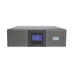
9PX3K3UG2
9PX5KG2
9PX6KG2
98.3 / 44.6
26.9x17.3x5.1 / 684x440x130
9PX6KIECG2
98.3 / 44.6
26.9x17.3x5.1 / 684x440x130
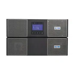
9PX8KG2
9PX11KG2
173.7 / 78.8
28.5x17.3x6.9 / 724x440x174
Description (EBM)
Weights (lb / kg)
Dimensions (inch / mm) D x W x H
9PXEBM180RTG2
144.8 / 65.7
25x17.3x5.1 / 636x440x130
9PXEBM240RTG2
136.7 / 62
26.4x17.3x5.1 / 670x440x130
Description (MBP)
Weights (lb / kg)
Dimensions (inch / mm) D x W x H
MBP6K208G2
6.6 / 3
4.9x5.1x9.4 / 125x130x239
MBP6KIECG2
5.3 / 2.4
4.9x5.1x9.4 / 125x130x239
MBP11K208G2
10.1 / 4.6
5.1x5.1x11.2/ 130x130x285

3.2
Rear Panel
UPS Rear Panels
9PX3K3UG2; 9PX5KG2; 9PX6KG2 (3U)
① Network Management Card
②
Battery
connector
③ USB communication port
④ RS232 communication port
⑤ Relay output contact
⑥ Connectors for ROO (Remote On/Off) and
RPO (Remote Power Off) control
⑦ Connector for HotSwap MBP detection
⑧ Connectors for automatic recognition of an
additional battery module
⑨ Primary group: outlets for connection of
critical
Equipment
⑩ Group 1: programmable outlets for
connection of
equipment
⑪ Group 2: programmable outlets for
connection of
equipment
⑫ Input/Output terminal blocks equipped with
power cord
⑬ Slot for optional communication card
(8000VA and 11000VA only)
9PX6KIECG2 (3U)
9PX8KG2; 9PX11KG2 (4U)

EBM Rear Panels
9PXEBM180RTG2 (3U)
① Connectors for automatic recognition of
battery modules
② Connectors for battery modules (to the UPS or
to the other battery modules)
③ Circuit Breaker (240V EBM only)
9PXEBM240RTG2 (3U)
MBP Rear Panels and description
The HotSwap MBP has a manual Bypass rotary switch with two positions:
• UPS => the load is supplied by the UPS
• Bypass => the load is supplied directly by the AC power source
2 lights indicate the Hotswap MBP power status:
• "UPS supply" green light: when active, the UPS output is available, the Bypass switch can be safely
turned to UPS position
• "Bypass mode" red light: when active, indicates that the Hotswap MBP is on "Bypass mode" (Bypass
switch turned to Bypass position)
Normal AC source switch:
Allow to safely switch off the AC source of the UPS, for UPS maintenance / replacing
MBP status detection:
A signal cable, with RJ11 connector to plug to the UPS, allows the communication to the UPS to manage
the MBP status, and the indication on UPS display panel of both following status:
• MBP connection to UPS
• Bypass switch position

MBP rear panels
MBP6K208G2
① Input/Output terminal blocks
② Input/Output/MBP-Detection connector to the
UPS
③ Manual Bypass switch
④ MBP-Detection connector to the UPS
⑤ Normal AC source switch
⑥ Sockets:
MBP6K208G2: 2 x L6-20P + 2 x L6-30P
MBP6KIECG2: 1 x C39 + 1 gang of 2 x C39 & 2x C13
MBP11K208G2: 4 x L6-30P
⑦ Breakers:
MBP6K208G2: 2 x 20A
MBP6KIECG2: 2 x 20A
MBP11K208G2: 4 x 30A
MBP6KIECG2

3.3
Optional accessories
Catalog Number
Description
Used With
Network-M3
Eaton Gigabit Network Card (SNMP v1/v3 and IP v4/v6 //
Ethernet 10/100/1000BaseT)
All
INDGW-
M2
Eaton Industrial Gateway Card (Modbus TCP / RTU)
All
Relay-MS
Eaton Relay card (1 x RS232 or 5 x Relay output)
All
INDRELAY-MS
Eaton Industrial relay card (5x relay outputs with dry
contacts for remote alarm information)
All
EMPDT1H1C2
Environmental Monitoring Probe Gen2, Compatibility :
Gigabit Network Card (Network-M2, Network-M3) /
Industrial Gateway Card (INDGW-M2) / Eaton ePDU
G3/G3+
All
9RK RK2PC
Rack kit /
2 Post Rail Kit
All
BINTSYS
Battery Integration System
All
EBMCBL180RT
2m EBM cable for 180V solution
9PX3KUG2, 9PX5KG2,
9PX6KG2, 9PX6KIECG2
EBMCBL240RT
2m EBM cable for 240V solution
9PX8KG2, 9PX11KG2
CBLADAPT180RT*
9PX Gen1/Gen 2 EBM cable adaptor 180V 1 meter length
9PX3KUG2, 9PX5KG2,
9PX6KG2, 9PX6KIECG2
CBLADAPT240RT*
9PX Gen1/Gen 2 EBM cable adaptor 240V 1 meter length
9PX8KG2, 9PX11KG2
9PX6KLC-10
Eaton 9PX L6-30 Line Cord 10ft
9PX3KUG2, 9PX5KG2,
9PX6KG2
9PXEBM180RTG2
Eaton 9PX Extended Battery Module 180V G2
9PX3KUG2, 9PX5KG2,
9PX6KG2, 9PX6KIECG2
9PXEBM240RTG2
Eaton 9PX Extended Battery Module 240V G2
9PX8KG2, 9PX11KG2
MBP6K208G2
HotSwap 9PX 6K external Maintenance ByPass G2
9PX3KUG2, 9PX5KG2,
9PX6KG2
MBP6KIECG2
HotSwap 9PX 6K IEC external Maintenance ByPass G2
9PX6KIECG2
MBP11K208G2
HotSwap 9PX 11K external Maintenance ByPass G2
9PX8KG2, 9PX11KG2
9PXTFMR5G2
Eaton 9PX Stepdown Transformer 5kW G2
9PX3KUG2, 9PX5KG2,
9PX6KG2, 9PX6KIECG2
9PXTFMR11G2
Eaton 9PX Stepdown Transformer 10kW G2
9PX8KG2, 9PX11KG2
9PXPPDM1G2
Eaton 9PX PPDM1 G2
All
9PXPPDM2G2
Eaton 9PX PPDM2 G2
All
Note:
* When using the 9PX Gen1/Gen 2 EBM cable adaptor, the RJ45 cable for automatic detection of EBM must not be used. The
EBM number must be manually set to the UPS.

4
Installation
4.1
Inspecting the equipment
If any equipment has been damaged during shipment, keep the shipping cartons and packing materials for the carrier or
place of
purchase and file a claim for shipping damage. If you discover damage after acceptance, file a claim for concealed damage.
To file a claim for shipping damage or concealed damage:
1.
File with the carrier within 15 days of receipt of the equipment
2.
Send a copy of the damage claim within 15 days to your service representative
Check the battery recharge date on the shipping carton label. If the date has passed and the batteries were never
recharged,
do not use the UPS. Contact your local service representative.

UPS package content
Verify that the following additional items are included
with the UPS:
① UPS
② Quick start
③ Instructions and Safety Information
④ Cable glands (2 for 3/5/6K) (3 for 8/11K)
⑤ RS232, 1.8m (1)
⑥ USB,1.8m (1)
⑦ Stands for tower installation (2)
⑧ Rack kit and screws
⑨ (2) IEC 10A, 1,2m for 6000 VA IEC only
EBM package content
If you ordered an optional Extended Battery Module (EBM), verify that the following additional items are included with the
EBM:
① EBM
② Quick start
③ Battery power cable, attached with
battery detection cable
④ Stabilizer bracket (4 screws included)
⑤ Rack kit and screws

MBP package content
If you ordered an optional Maintenance ByPass (MBP), verify that the following additional items are included with the MBP
:
MBP6K208G2
① MBP
② Quick start
③ MBP Cord set (For 6k MBP only)
④ Cable glands
⑤ Ears for rack mounting
⑥ MBP fixation ears
⑦ Kraft envelop with screws
⑧(2) conduits with internal wires for UPS
Input/Output connection (for 11k MBP only)
MBP6KIECG2
MBP11K208G2

4.2
Unpacking the UPS
Unpacking without removing the batteries
The UPS is wrapped in a paper tray lifting system. It is prevented from slipping by the cardboard (blue circles) pasted on the paper
tray. The UPS can be lifted by two people using the 2 “handles” per side (red circles).
Take care to carry the product horizontally.
The UPS is heavy, wear appropriate safety equipment.
Removing the batteries before unpacking
The carton box is designed to give access to front panel without removing the UPS from the carton. Follow the steps below to get
access to front panel and to remove the battery packs
1) Open the carton box
2) Remove the rail kit and
foam top of the product
3) Remove the cardboard
board inside the carton, use
knife to remove the carton
cover front of the product
4) Remove the front panel
and battery pack in the
product.
After having removed the battery pack, the product frame could be handled out by one person:
4.3
Recommended positions
Installation in tower position
If you ordered other UPS accessories, refer to specific user manuals to check the tower installation with the UPS.
To install
the UPS:
•
Place the UPS on a flat, stable surface in its final location.
•
Always keep 6" or 150 mm of free space behind the UPS rear panel 6" or for ventilation.
•
If installing additional cabinets, place them next to the UPS in their final location.
Before installing the UPS in tower position, you can rotate the LCD. Follow steps to adjust the orientation of the LCD panel
and of
the logo.
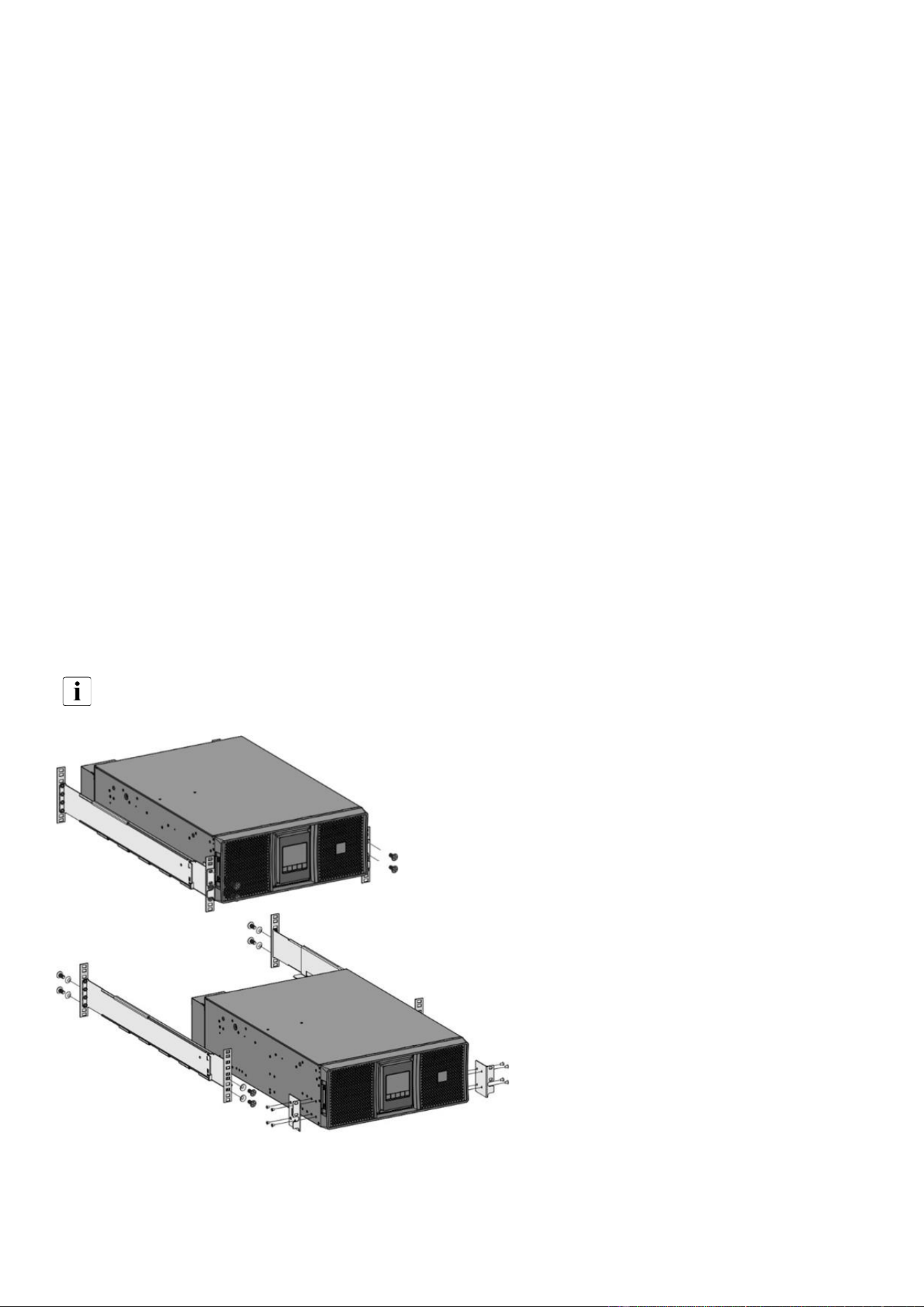
Installation in rack position
Follow steps bellow for module mounting on the rails. As UPS is heavy, it is advised to remove the batteries before
mounting the UPS on the rack.
The rails and necessary hardware are supplied by Eaton.
UPS installation in rack
position without removing the battery
① Screw the rail on the back of the rack.
② Screw the rail on the front of the rack
using the two holes at the bottom.
③ Screw the ears plate to the UPS.
④ Place the UPS on the rails and screw the
ears plate to the top hole of the rail.

3000VA, 5000VA and 6000VA UPS: Installation in rack position by removing the battery
Follow steps 1 to 16.
Steps 1 to 6: Remove the battery
Steps 7 to 10: Install the Rack Kit and Fix the UPS cabinet (w/o battery)
Steps 11 to 16: Replace the battery and the front panel

8000VA and 11000VA UPS: Installation in rack
position by removing the battery
Follow steps 1 to 16.
Steps 1 to 7: Remove the battery
Steps 8 to 11: Install the Rack Kit and Fix the UPS cabinet (w/o battery)
Steps 12 to 18: Replace the battery and the front panel

4.4
EBM connection
Extended runtime with up to twelve Extended Battery Modules (EBMs) per UPS
Tower installation
When 11KVA UPS is used with more than 8 EBMs (between 8 and 12), additional PE wires (cross-sectional area identical to
input) are required, see illustration below:

A small amount of arcing may occur when connecting an EBM to the UPS. This is normal and will
not harm personnel. Insert
the EBM cable into the UPS
battery connector quickly and firmly.
1.
Attach the UPS and the EBMs to each other using the supplied mounting plate.
2.
Connect the EBMs power cable and the
attached battery detection cable as shown in the
picture.
3.
Verify that the EBM connections are tight and that adequate bend radius and strain relief exist for each cable
4.
Switch On the EBM breaker (for 240V EBM only)
180V EBM for 3000VA, 5000VA and 6000VA UPS
240V EBM for 8000VA and 11000VA UPS
Rack installation
A small amount of arcing may occur when connecting an EBM to the UPS. This is normal and will
not harm personnel. Insert
the EBM cable into the UPS
battery connector quickly and firmly.
To increase stability, it is preferable to place the EBM below the UPS.
1.
Attach the UPS and the EBMs to each other using the supplied mounting plate.
2.
Connect the EBMs power cable and the attached battery detection cable as shown in the picture.
3.
Verify that the EBM connections are tight and that adequate bend radius and strain relief exist for each cable
4.
Switch On the EBM breaker (for 240V EBM only)

180V EBM for 3000VA, 5000VA and 6000VA UPS
240V EBM connection to 8000VA and 11000VA UPS

4.5
UPS connection
Hardwired connection
UPS connection without HotSwap MBP module
Check that the indications on the name plate located on the back of the UPS correspond to the AC-power
source and the
true electrical consumption of the total load.
Caution: switch off utility power to the distribution point where the UPS will be connected. Be absolutely sure
there is no power.
Note: For 3000VA, 5000VA and 6000VA only. The UPS is already equipped with a L6-30P input cord.
Directly connect the L6-30P cord to the power outlet
Note: For 3000VA, 5000VA and 6000VA, the user can also choice to remove the I/O box to connect the UPS through the
terminal block, following the below steps:
Unscrew the I/O box
3000VA, 5000VA and 6000VA 8000VA and 11000VA

Remove the blue circular cover (Input) and screw the
cable gland.
3000VA, 5000VA and 6000VA
8000VA and 11000VA
Strip the copper supply cable keeping the Earth cable longer for safety purpose
Insert the supply cable in the I/O box
3000VA, 5000VA and 6000VA
8000VA and 11000VA
High leakage current: Earth connection essential before connecting supply

Recommended protective devices and cable cross-sections
3000VA, 5000VA and 6000VA
8000VA and 11000VA
CAUTION, for 8000VA and 11000VA: there is a risk of voltage backfeed. Before working on this circuit, isolate the UPS, then check
for Hazardous Voltage between all terminals including the protective earth.
A suitable 2 poles AC contactor at the UPS input may be implemented as an external backfeed protection.
Recommended upstream protection
The upstream circuit breaker for Normal AC/Bypass AC must be easily accessible. The unit can be disconnected from AC power
source by opening this circuit breaker.
UPS power rating
Upstream circuit breaker
3000VA / 5000VA
6000VA (default installation, with L6-30P)
D curve 2 poles – 30A for cULus,
32A for others
6000VA (Hardwired connection)
D curve 2 poles – 40A*
1
8000VA
D curve 2 poles – 50A
11000VA
D curve 2 poles – 80A
*2
*1
If hardwired, it is required to use a 40A breaker and to change the connection mode in the user settings menu.
*2
If the UPS load is less than 90%; Or the total battery Ah less than 20Ah, the UPS will limit the charger current to 4A (0.2*20 = 4A), in
this case, you could select the 70A (in US/CSA)/ 63A(others) upstream circuit breaker. (these conditions are not certificated)
Do not use 30 mA RCD/ELCB breaker upstream the UPS.
Recommended cable cross-sections for standard installation
UPS power rating
Minimum input wire size
Minimum output wire size
Min
Tightening
torque
Maximum
wire size
L1
N(L2)
L1
N(L2)
3kVA
NA, Standard
configuration L6-30P
12AWG / 6mm
2
10.6 lb-in
6 AWG /
16mm
2
5kVA
10AWG / 6mm
2
6kVA
(with L6-30P input)
10AWG / 6mm
2
6kVA
(with Hardwire input)
8AWG / 6mm
2
*
8AWG / 6mm
2
8kVA
6AWG / 10mm
2
*
8AWG / 10mm
2
22 lb-in
4 AWG /
25 mm
2
11kVA
4AWG / 10mm
2
*
6AWG / 10mm
2
* High leakage current, use additional PE conductor of the same cross-section area as the original PE conductor.
NOTE For Supply connections, use wires suitable for at least 90°C copper or equivalent.
AWG used in US/CSA, mm
2
used in others.

Screw the electric cables, starting by the earth wire
Screw the I/O box and tighten the cable gland
3000VA, 5000VA and 6000VA
8000VA and 11000VA
Connect the output cables, switch on the breaker and start the UPS
4.6
Register warranty
Register warranty at https://content.eaton.com/product-registration.

4.7
Connection with MBP
The Eaton® HotSwap MBP G2 module makes it possible to service or even replace the UPS without affecting the
connected loads (HotSwap function).
You can safely eliminate the effects of UPS maintenance and guard the integrity of your equipment.
Providing outstanding reliability, the Eaton HotSwap MBP G2 unique benefits include:
• Easy and fast connection to UPS due to Input/Output and signal “all in one” patented connector
• “make before break” feature to allow full servicing (electrical power continuity) when switching from UPS position to
Bypass (and vice versa)
• Communication feature with UPS*: detection of MBP connection and switch position (Normal or Bypass) (* works only with
some approved EATON UPS - contact your Eaton reseller for more information)
• Load connection by both terminal blocks and NEMA outlets
• Adjustable 19’’ Rack kit and multiple positions Tower installation kit provided
• Backed by worldwide agency approvals
Note: In the configuration "UPS + EBM", the MBP must be mounted at the back of EBM.
Mechanical installation in rack position
For the MBP used with 8000VA and 11000VA UPS, depending on the configuration, there are two different assemblies,
identified with letters
(UPS only) and
(UPS+EBM).
MBP6K208G2 and MBP11K208G2:
Final assembly position:
MBP6K208G2 used with 3000VA, 5000VA and 6000VA UPS
MBP11K208G2 used with 8000VA and 11000VA UPS

Follow the steps below to install the MBP in rack position.
1. Screw the ears on each MBP side.
MBP6K208G2 used with 3000VA, 5000VA and 6000VA UPS
MBP11K208G2 used with 8000VA and 11000VA UPS
2. Mount the MBP with its ears on the UPS rack.
MBP6K208G2 used with 3000VA, 5000VA and 6000VA UPS
MBP11K208G2 used with 8000VA and 11000VA UPS

MBP6KIECG2:
Final assembly position:
MBP6KIECG2 used with 6000VA IEC UPS
MBP6KIECG2 used with 6000VA IEC UPS and 180V EBM
Follow the steps below to install the MBP in rack position.
1. Screw the ears on each MBP side.
2. Mount the MBP with its ears on the rack.

Mechanical installation in tower position
Depending on the configuration, there are four different assemblies, identified with letters A, B, C and D.
The different ways to mount the MBP with the UPS or the "UPS+EBM" are identified by the A, B, C & D letters.
MBP6K208G2 and MBP11K208G2:
Final assembly position:
MBP6K208G2 used with 3000VA, 5000VA and 6000VA UPS
MBP11K208G2 used with 8000VA and 11000VA UPS
MBP6K208G2 used with 3000VA, 5000VA and 6000VA UPS +
180V EBM
MBP11K208G2 used with 8000VA and 11000VA UPS +
240V EBM

Follow the steps below to install the MBP in tower position.
Screw the ears on each MBP side.
MBP6K208G2 used with 3000VA, 5000VA and 6000VA UPS
MBP11K208G2 used with 8000VA and 11000VA UPS
Mount the MBP with its ears on the UPS or EBM
MBP6K208G2 used with 3000VA, 5000VA and 6000VA UPS. MBP11K208G2 used with 8000VA and 11000VA UPS
.

MBP6KIECG2:
Final assembly position:
MBP6KIECG2 used with 6000VA IEC UPS
MBP6KIECG2 used with 6000VA IEC UPS and EBM
Follow the steps below to install the MBP in tower position.
Screw the ears on each MBP side.
Mount the MBP with its ears on the UPS or EBM

MBP electrical connection
Caution: switch off utility power to the distribution point where the MBP will be connected. Be
absolutely sure there is no power.
Access to the terminal block, detach the knockouts from the AC terminal wiring box and install the cable glands included in the
MBP accessory kit.
MBP 6k
MBP 11k

Insert the electrical cables.
Follow below instructions for upstream protection and cable cross section.
Use copper cable only, and not aluminum.
Recommended upstream protection
MBP
MBP rating at 208V
Upstream circuit breaker
(CB)
MBP 6k
5400VA/4800W with 6kVA UPS
D curve 2 poles – 30A
MBP 11k
8000VA/8000W with 8KVA UPS
11000VA/11000W with 11KVA UPS
D curve 2 poles – 50A
D curve 2 poles – 80A
*1
*1
If the UPS load is less than 90%; Or the total battery Ah less than 20Ah, the UPS will limit the charger current to 4A (0.2*20 = 4A), in
this case, you could select the 70A( in US and CSA) / 63A(others) upstream circuit breaker. (these conditions are not certificated)
Do not use 30 mA RCD/ELCB breaker upstream the UPS.
Recommended cable cross-sections for standard installation
MBP and UPS
Minimum input wire size
Minimum output wire size
Min
Tightening
torque
Maximum
cable size
L1
N(L2)
L1
N(L2)
9PX3K3UG2 + MBP6K208G2
10AWG / 6 mm²*
12AWG / 6 mm²
16 lb-in
6AWG / 16
mm2
9PX5KG2 + MBP6K208G2
10AWG / 6 mm²*
10AWG / 6 mm²
9PX6KG2
*2
+ MBP6K208G2
9PX6KIECG2
*2
+ MBP6KIECG2
10AWG / 6 mm²*
10AWG / 6 mm²
9PX8KG2 + MBP11K208G2
6AWG / 10 mm²*
8AWG / 10mm²
22 lb-in
4AWG / 25
mm2
9PX11KG2 + MBP11K208G2
4AWG / 10 mm²*
6AWG / 10 mm²
AWG used in US/CSA, mm
2
used in others.
For Supply connections, use wires suitable for at least 90°C copper or equivalent.
Note:
* High leakage current, use additional PE conductor of the same cross-section area as the original PE conductor.
*
2
When 6K UPS used with MBP, the UPS cannot select the Hardwired method in the user settings menu, the power
rating could just be 5400VA/4800W

Strip the copper supply cable keeping the Earth cable longer for safety purpose.
Insert the cables
MBP 6k
MBP 11k
Tighten well the cable glands
MBP 6k
MBP 11k
Close the I/O box terminal
MBP 6k
MBP 11k
s

Connection between MPB and UPS
For the electrical connection on the UPS side, follow the steps described in the chapter "Hardwired connection".
For MBP 6k Only
: Connect the MBP cord set.
Connect the MBP detection cable to the UPS
Power up your installation
Switch on the input circuit breaker of your installation. The installation is powered up and can be used.
HotSwap MBP module test
Set Manual Bypass switch to Bypass position and check that the load is still supplied.
Set Manual Bypass switch back to Normal position.
5
Interfaces and communication
5.1
Control panel
The screen provides useful information about the UPS itself, load status, events, measurements and settings.
① Power ON indicator (green)
② On battery indicator (orange)
③ On bypass indicator (orange)
④ Alarm indicator (red)
⑤ Escape
⑥ Up
⑦ Down
⑧ Enter
⑨ On/Off button
⑩ Led bar
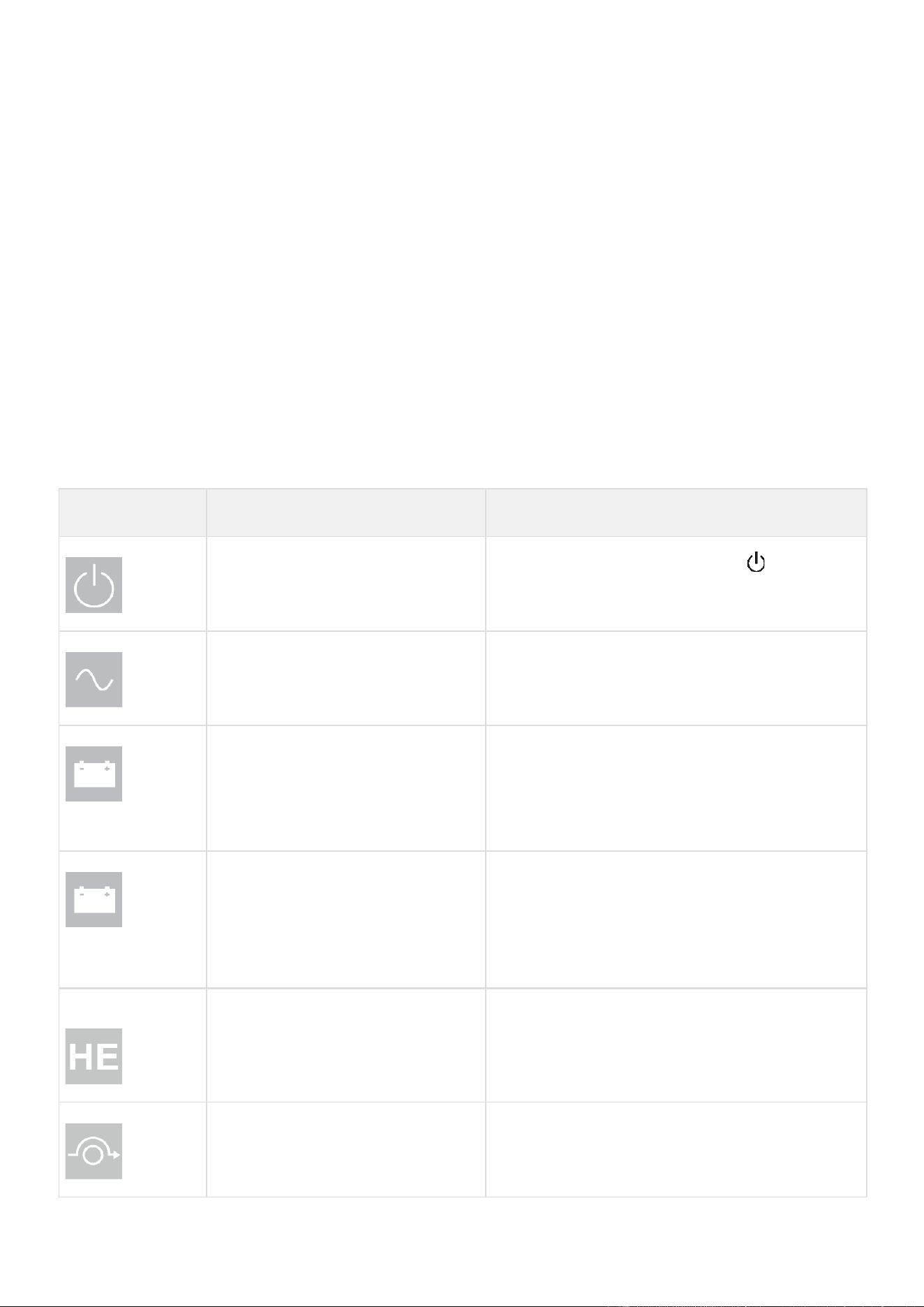
Led indicator
The following table shows the indicator status and description :
The LED bar ⑩ has been implemented to provide a quick visual reference of UPS status "at-a-glance".
Indicator
Status
Description
Green
On
The UPS is "ON" and the load is protected.
Orange
On
The UPS is in battery mode and the load is protected.
Orange
On
The UPS is in bypass mode.
Red
On
The UPS has an active alarm or fault. See troubleshooting page for additional
information.
Led bar
Static blue
The UPS is "ON" and the load is protected.
Flashing blue
The UPS is on battery or the battery service age warning is reached.
Static red
The UPS has an active alarm or fault.
5.2
LCD description
① Operation status
② Load/equipment status
③ Load group information
④ Battery status
By default, or after 5 minutes of inactivity, the LCD displays the screen saver.
The backlight LCD automatically dims after 5 minutes of inactivity. Press any button to restore the screen.
Note. If other indicator appears, see troubleshooting page for additional information.
The following table describes the status information provided by the UPS :
Operation status
Possible
cause
Action
Standby mode
The UPS is OFF, waiting for start-up
command from user
Equipment is not powered until button
is pressed
during start up and the green "normal mode" LED
indicator is illuminated.
Normal mode
The UPS is operating normally.
The UPS is powering and protecting the equipment.
On Battery
One beep every 10
seconds
A utility failure has occurred and the
UPS is operating in Battery mode.
The UPS is powering the equipment with battery power.
Prepare your equipment for shutdown.
End of backup time
1 beep every 3
seconds
Single beep
The UPS is in Battery mode and the
battery is running low.
This warning is approximate, and the actual time to
shutdown may vary significantly. Depending on the UPS
Load, the "Battery Low" warning may occur before the
battery reaches 20% capacity remaining.
High Efficiency
mode
The UPS is operating in High Efficiency
mode.
The UPS is powering and protecting the equipment.
Bypass mode
An overload or a fault has occurred, or
a command has been received, and the
UPS is on Bypass mode.
Equipment is powered but not protected by the UPS.

5.3
Display functions
Press the Enter (
⮠
) button to activate the menu options. Use the two middle buttons (
⯅
and
⯆
) to scroll through the menu
structure. Press the Enter (
⮠
) button to select an option. Press the (
ESC
) button to cancel or return to the previous menu.
Menu map for display functions
Main menu
Submenu
Display information or Menu function
Measurements
Load: W, A, VA, pF
[Input/Output] : V, Hz [Efficiency] : %
[Battery Info] : %, min, V, Age service, Age Warning, Replacement Battery
Packs
[Average power usage] : Total Wh
[Cumulative power] : Total KWh, Since
Control
Go to Bypass
The user has the possibility to force the Ups to go to Bypass mode, only if the
Ups mode is in Online or in battery mode.
Load Segments
Group 1: ON / OFF Group 2: ON / OFF
These commands overrule user settings for load segments.
Start battery test
Starts a manual battery test (possible if load >10% and battery >80%)
Change battery
Disable charger, Replace battery, Update settings
Connectivity test
Dry contacts test, Relay card test, Line failure test, Battery low test
Functions reset
Reset fault state, Reset power usage, Reset battery life, NMC Card reset,
Restore factory settings
Settings
Local settings
Sets product general parameters, see User settings
Input / output
settings
Sets input and output parameters
ON / OFF settings
Sets ON / OFF conditions
Battery settings
Sets battery configuration
Communication
settings
Sets communication parameters
Event log
View Alarms
Displays the alarms stored
View Events
Displays the events stored
View All
Displays the faults, alarms and events stored
Reset All
Clears the faults, alarms and events stored
Fault log
Fault list
Displays the faults stored
Reset fault list
Clears faults
Identification
Type / Model / Part Number / Serial Number / UPS Firmware / NMC Firmware
/ IPV4 Address / IPV6 Address / Com card MAC Address /Detected accessories
Registration
Links to Eaton registration website

5.4
User settings
The following table displays the options that can be changed by the user.
Main Menu
Submenu
Available
settings
Default
settings
Local settings
Language
[English] [Français] [Deutsch] [Español]
[Portugues] [Italiano] [Simplified
Chinese] [Japanese]
Menus, status, notices and alarms, UPS
fault, Event Log data and settings are in
all supported languages.
[English]
Automatic message for user
configuration when UPS is
powered for the first time.
Date / time
Format: [International] [US]
[US]
LCD
Modify LCD screen brightness
and contrast
to be adapted to room light conditions.
[0]
Audible alarm
[Enabled] [Disabled on battery] [Always
disabled] Enable or disable the buzzer if
an alarm occurs.
[Enabled]
Level: [High] [Low]
[High]
Protected access
[Enabled] [Disabled]
Allow the user to
lock the
settings modification.
[Disabled]
In/Out settings
Output voltage
[200 V] [208 V] [220 V] [230 V]
[240 V]
[208 V]
Output frequency
Mode: [Normal] [Converter] [Marine]
Frequency can be changed in Frequency
[Converter] mode In [Marine] mode
output frequency
follows input frequency
[Normal]
Output Mode
Mode: [Industrial] [IT] [Custom]
Overload: [Inv>Stop] [Inv>BP]
[Inv>BP>Inv]
Short-circuit: [Inv>Stop] [Inv>BP]
[Inv>BP>Inv]
[IT]
[Inv>BP>Inv]
[Inv>Stop]
Input V hysteresis
Sets input voltage hysteresis from [1] to
|10V]
[10V]
High efficiency
[Enabled] [Disabled]
Power the output from Bypass
for high efficiency
[Disabled]
Bypass settings
[Volt low] [Volt high] [Qualify] [Hz synch]
[Unsynch]
[160V];
[276V];
[In spec];
[5%];
[Half cycle]
Load segments
[Auto start delay]
UPS:[No delay]; Group1:[3s];
Group2:[6s]
[Auto shutdown delay]
UPS:[Disabled]; Group1:
[Disabled];
Group2:[Disabled]
Overload prealarm
[10%] … [102%]
Load % when overload alarm occurs
[102%]
Power Limit
[Enabled] [Disabled] Disabled/ Enabled
UPS power limit mode on 5K/6K/8K/11K.
If Enabled nominal power change to
4000VA/4000watt
[Disabled]

Main Menu
Submenu
Available
settings
Default
settings
Dust Proofing
[Enabled] [Disabled]
If set to Enabled, a 40% derating will be
applied to allow functioning with a dust
filter.
[Disabled]
Input wiring (for 6K
models
9PX6KG2/9PX6KIECG2
[L6-30P] [Hardwired]
[L6-30P]
Redundancy mode
[Unitary UPS] [Hot Standby]
[Unitary UPS]
ON/OFF settings
Start/Restart
[Cold start] [Auto restart] [Auto start]
[Start on bypass]
[Cold start] : ON [Auto
restart] : ON [Auto start] :
OFF
[Start on bypass] : OFF
Forced reboot
[Yes] [No]
[Timer] [10s] … [180s]
When mains recovers during a shutdown
sequence:
If set to Enabled, shutdown sequence will
complete and wait 10 seconds prior to
restart,
If set to Disabled, shutdown
sequence will
not complete,
UPS stays on.
[Yes]
[10s]
Energy saving (W,%,
delay)
[Yes] [No]
[Time] [0min] … [15min]
[Level] [10W] …
[1000W - Nominal Power]
If Enabled, UPS will shut-down
after
defined duration of back-
up time, if load is
less than set value.
[No]
[5min]
[1000W]
Sleep Mode
[Enabled] [Disabled]
[Timer] [10min] … [120min]
If Disabled,
LCD and
communication will turn OFF
immediately after UPS is OFF. If Enabled,
LCD and communication stays ON for
the set time period after UPS is OFF
(default 90 min).
[Enabled]
[90min]
Site Wiring Fault
[Enabled] [Disabled]
Prevents the UPS from starting if the
phase and neutral wires are swapped.
[
Disabled
]
Power Off alert
[Enabled] [Disabled]
If enabled, activates a confirmation
screen that requires user confirmation
after pressing the power
button, before
UPS shutdown
occurs.
Remote
shutdown, ROO, RPO, Input signals will
never request user confirmation, even
if the setting is enabled
[Yes]
Bypass standby
[Enabled] [Disabled]
[Disabled]
Auto battery test
In ABM® cycling mode: [No test] [Every
ABM® cycle]
In constant charge mode: [No test] [Daily]
[Weekly] [Monthly]
[Every ABM® cycle] [Weekly]

Main Menu
Submenu
Available
settings
Default
settings
Battery settings
Battery age warning
[Disabled][Preventive][6-120]
[Predictive]
If Preventive, the UPS displays a battery
replacement reminder through the front
LCD and any installed network
communication card after the indicated
timeframe has elapsed (default 48
months).
[Predictive]
Refer to Advanced Battery
Management + section
Low battery warning
[Capacity] [0%] … [100%] [Runtime]
[0min] … [60min] The alarm triggers
when the set percentage of battery
capacity or remaining back-up
time is
reached.
[0%]
[3min]
Restart batt. level
[0%] ... [100%]
Automatic restart will occur
only when
the set percentage
of battery charge is
reached,
and "Auto Restart" is enabled
and set to ON. A setting of 0%
allows
immediate automatic restart when
utility returns after a UPS shutdown due
to an extended power outage.
[0%]
Battery charge mode
[ABM® cycling] [Constant charge]
[ABM®
cycling]
External battery
[Auto detection] [Manual EBM set.]
[Manual battery set.][No Battery]
[Auto detection]
Using standard EBM, UPS
automatically detects the
number of EBM connected
Charger current
[2A] [4A] [6A][8A]
It is the maximum charging current. The
UPS will adapt charger current to reduce
charging time and maximize battery life.
[8A]
Depending on the
environment (voltage, load,
etc.) the current can be lower
than 8A
Deep disch. protect.
[Enabled] [Disabled]
If set to Enable, the UPS
operates within
the normal
design range of the battery
during discharge.
If set to Disable, the UPS allows deeper
battery discharge to extend battery
runtime at the expense of long-term
battery life (warranty is also void if set to
disable).
[Enable]
[ROO] [RPO] [DB9-4]
Sets Input signals parameters (function,
delay, operation) through external
contact connectors or RS232 port.
ROO port:
- [Function]: [No] [ROO] [RPO] [Building
alarm][Forced bypass] [On
generator] [Remote shutdown]
- [Delay]: [0s]
…
[999s]
- [Active]: [Open] [Closed]
[No]
[0s]
[Closed]
Input signals
RPO port:
- [Function]: [No] [ROO] [RPO] [Building
alarm][Forced bypass] [On
generator] [Remote shutdown]
[No]
[0s]
[Open]

Main Menu
Submenu
Available
settings
Default
settings
- [Delay]: [0s]
…
[999s]
- [Active]: [Open] [Closed]
DB9-4 port:
- [Function]: [No] [ROO] [RPO] [Building
alarm][Forced bypass] [On
generator] [Remote shutdown]
[No]
[0s]
[High]
Comm settings
- [Delay]: [0s]
…
[999s]
- [Active]: [Low] [High]
[Relay1] [Relay2] [DB9-1]
[DB9-7] [DB9-8]
Sets events or fault that will actuate
Output signal
parameters through
external
contact connector or RS232 port
[Relay1] [Relay2]: [On bat] [Low bat]
[Bat fault] [Bypass] [UPS OK] [Load
protected] [Load powered] [General
alarm]
[OVL pre-alarm] [Batt Disconn]
Outputs signals
[DB9-1]: [On bat] [Low bat]
[Bat fault]
[Bypass] [UPS OK] [Load
protected]
[Load powered]
[General alarm] [OVL
pre- alarm] [Batt Disconn]
[DB9-7]: [On bat] [Low bat]
[Bat fault]
[Bypass] [UPS OK] [Load
protected]
[Load powered]
[General alarm] [OVL
pre- alarm] [Batt Disconn]
Comm settings
[DB9-8]: [On bat] [Low bat]
[Bat fault]
[Bypass] [UPS OK] [Load
protected] [Load
powered]
[General alarm] [OVL pre-
alarm] [Batt Disconn]
Remote commands
[Enabled] [Disabled]
If Enabled, shutdown or restart
commands from software are authorized.
[Enabled]
Shutdown commands
[Send CMD] [Output OFF] [OFF delay]
[Restart]
Sets events or fault that will actuate
Output signal
parameters through
external
contact connector or RS232 port
[Send CMD]: [Yes] [No]
[Output OFF]: [No] [UPS]
[Group 1]
[Group 2] [Group 1 + 2] [OFF delay]: [0s]
…[65534s] [Restart]: [Yes] [No]
For a proper server shutdown
please
make sure that the Output OFF delay is
long enough
Send CMD: [No] Output OFF:
[No] OFF delay: [0s] Restart:
[Yes]
On battery notice delay
[0s] ... [99s]
Sets delay before providing an on battery
notice to software.
[0s]

Main Menu
Submenu
Available
settings
Default
settings
General alarm
[On battery] [Battery fault]
[Overload
pre-alarm] [Internal
fault] [Ambient
temp.] [Fan lock] [Bypass overload]
[Current limit] [Short circuit] [Inverter
overload] [Power overload] [Low
battery] [On Bypass] [UPS OK] [Load
protected] [Load powered] [Ext Charg.
on]
Defines which event or fault will
generate a general alarm
through Output
signal screen.
[Internal fault]
Set Comm Card1/Card2
IPv4
[DHCP] : [Yes] [No]
[IP Adress] [Subnet mask] [Gateway]
The UPS does not display the IPv4
settings menu by default, you can
activate it by a communication
command.
[Yes] XXX.XXX.XXX.XXX
5.5
Advanced Battery Management +
Eaton ABM+ (Advanced Battery Management) implements a machine learning algorithm providing battery health status.
When set to predictive mode, the UPS will be able to provide an accurate remaining service time prediction based on real
UPS
usage condition.
A battery replacement warning (that includes the battery P/N) will be triggered at the most appropriate time to help user keeping
the UPS operating at its best performance.
5.6
Communication ports
Connection of RS232 or USB communication port
1. Connect the RS232 or USB communication cable to the serial or USB port on the computer equipment.
2. Connect the other end of the communication cable to the USB or RS232 communication port on the UPS
The UPS can now communicate with Eaton power management software.

Characteristics of the contact RS232 communication port
Contact characteristics (optocoupler):
•
Voltage: 48 V DC max
•
Current: 25 mA max
•
Power: 1.2 W
Installation of the communication cards
The UPS is delivered with a Network-M3 card already
mounted in the slot 1.
If you need to change the card or to add a second communication cart ( a
second slot is available on the
8000VA and
11000VA only
), follow the below instructions:
Note: It is not necessary to shutdown the UPS before installing a communication card.
3000 / 5000 / 6000 VA
8000 / 11000 VA
1.
Remove the slot cover secured by screws
2.
Insert the communication card in the slot.
3.
Secure the card cover with the two screws to
connect the comm card to the ground.
Connectivity cards
Connectivity cards allow the UPS to communicate in a variety of networking environments and with different types of
devices. The
9PX G2 models have one available communication bay for the following connectivity cards:
•
Gigabit Network card ( Network-M3) : provides a Gigabit Ethernet connection and enables secure UPS
monitoring over
HTTPS web browser interface, SNMP v1/v3 protocol and email alarms. In addition, up to 3 Environmental Monitoring
Probes can be attached to obtain humidity, temperature, smoke alarm, and security information.
•
Industrial Gateway card (INDGW-M2) : Provides Modbus RTU and Modbus TCP communication support in addition
to the
same secure UPS monitoring, management and sensor capability as the Gigabit Network card.
•
Relay-MS card : provides isolated dry contact (Form-C) relay outputs for UPS status: Utility failure, Battery low, UPS
alarm/OK,
or on Bypass.
•
INDRELAY-MS : The Industrial relay Card-MS (INDRELAY-MS) provides a simple way to remotely input UPS information
to an
alarm system, PLC or a computer system via dry contacts. It offers five isolated dry contact outputs and one isolated dry
contact input.
Pin
Signal
Direction
Function
1
Bat low
Output
Low Battery Output
2
TxD
Output
Transmit to external
device
3
RxD
Input
Receive from external
device
4
I/P SIG
Input
-
5
GNDS
-
Signal common tied to
chassis
6
NC
Not Connected
7
UPS OK
Output
UPS OK
8
BAT mode
Output
UPS on battery mode
9
+5V
Output
Power supply for
external signal or
options


5.7
UPS remote control functions
Programmable signal inputs
The 9PX G2 incorporates several programmable signal inputs: one Remote Power Off (RPO) input terminal, one Remote On/Off
(ROO) input terminal, one RS-232 input (pin-4).
Signal inputs can be configured (see Settings > Comm settings > Signal Input) to have one of the following functions:
Function
Description
No
No function. (Please choose a function if you want to use input signal.)
RPO
Remote Power off (RPO) is used to shutdown the UPS remotely.
ROO
Remote On/Off allows remote action of a button or other interface to switch
On/Off
the UPS. (Cold start is prohibited while using the ROO function.)
Forced bypass
If feeding the load the unit goes to bypass operation and stays there regardless
of
the bypass state until the input is inactivated.
Building alarm
Active input generates an alarm “building alarm”.
On generator
Active input disables synchronization and disable bypass output.
Shutdown commands
Active input turns UPS output (or outlet groups) off after a user defined shutdown
delay but keeps on charging batteries according to a selected charging
scheme; inactive input does not abort shutdown countdown. Depending on the
“Restart” parameter (see Settings > Comm Settings > Shutdown commands)
the unit may startup automatically.
Warning: signal inputs have no function by default; please choose a function through the LCD (Settings > Com
settings > Input signals).
See below 2 examples of configuration with RPO terminal used as RPO function and ROO terminal use as ROO function:
Remote Power Off (RPO)
RPO is used to shutdown the UPS remotely when the contact is open. This feature can be used for shutting down the load
and the
UPS by thermal relay, for example, in the event of room over temperature. When RPO is activated, the UPS turns
off the output
and shuts down all power converters immediately (except for logic power). The UPS remains "ON" to alarm
the fault.
The RPO circuit is a safety extra low voltage (SELV) circuit. This circuit must be separated from any hazardous voltage
circuits by reinforced insulation.
•
The RPO must not be connected to any utility connected circuits. Reinforced insulation to the utility is required. The
RPO
switch must be a dedicated latching-type switch not tied into any other circuit. The RPO signal must remain active for at
least 250 ms for proper operation.
•
To ensure the UPS stops supplying power to the load during any mode of operation, the input power must be
disconnected
from the UPS when the Remote Power Off function is activated.
RPO connections:
Leave the RPO connector installed in the RPO port on the UPS even if the RPO function is not needed.
RPO
Comments
Connector type
Terminal, 14 AWG Maximum
wires
Terminal rating
60 V DC/30 V AC 20 mA max

Remote On/Off (ROO)
•
Remote On/Off allows remote action of button to switch On/Off the UPS.
•
When contact changes from open to closed, the UPS is switched-on (or stays On).
•
When contact changes from closed to open, the UPS is switched-off (or stays Off).
•
On/Off control via button has priority over the remote control.
The ROO function is only active after the first use of the "Remote OFF" function.
Remote control connection and test
Warning. This connector must only be connected to SELV (Safety Extra-Low Voltage) circuits.
3.
Check the UPS is shut down and the electrical supply network disconnected.
4.
Remove RPO connector from the UPS by removing the screws.
5.
Connect a normally closed volt-free contact between the two pins of connector.
6.
Plug the RPO connector into the back of the UPS and fix the screws.
7.
Connect and restart the UPS according to the previously described procedures.
8.
Activate the external remote shut down contact to test the function.
Always test the RPO function before applying your critical load to avoid accidental load loss.
Programmable signal outputs
The 9PX G2 incorporates several programmable signal outputs: Two relay outputs and two optocoupler outputs (DB9 pins
1, 7
and 8). Signal outputs can be configured (see Settings > Comm settings > Output Signals) to report the following information:
Signal
Default assignment
Description
On battery (On Bat)
DB9-Pin 8
UPS is in battery mode
Low battery (Low Bat)
DB9-Pin 1
UPS is in battery mode and has reached the low battery
alarm threshold
Battery fault
Relay output (1)
Battery fault
UPS OK
DB9-Pin 7
Load is powered with no alarm
(from inverter or bypass)
Load protected
-
UPS is on inverter, with no alarm and ready to go to
battery
Load powered
-
Load is powered
(from inverter or bypass)
General alarm
-
Choose events that will trigger this alarm trough the
LCD
(Settings > Comm settings > General alarm).
For more information on possible events please look
at
User settings
OVL pre-alarm
-
Overload pre-alarm
Bat disconnected
-
Battery is disconnected
Bypass
Relay output (1)
UPS is operating in Bypass mode
ROO
Comments
Connector type
Terminal, 14 AWG Maximum wires
Terminal rating
60 V DC/30 V AC 20 mA max
Contact open: shut down of UPS.
To return to normal operation, deactivate the external remote shut down
contact and restart the UPS from the front panel.
Normally closed

(1) Relay output:
5.8
Eaton Intelligent Power Software suite
Eaton Intelligent Power Software suite is available from eaton.com/downloads.
Eaton Software suite provides up-to-date graphics of UPS power and system data and power flow.
It also gives you a complete record of critical power events, and it notifies you of important UPS or power information.
If there
is a power outage and the 9PX G2 UPS battery power becomes low, Eaton Software suite can automatically shut
down your
computer system to protect your data before the UPS shutdown occurs.
5.9
Cybersecurity
Eaton is committed to minimizing the Cybersecurity risk in its products and employs cybersecurity best practices and the
latest
cybersecurity technologies in its products and solutions, making them more secure, reliable and competitive for our
customers. Eaton also offers Cybersecurity Best Practices whitepapers to its customers, referenced at
www.eaton.com/cybersecurity.

6
Operation
6.1
Start-up and normal operation
Check that the indications on the name plate located on the back of the UPS meets to the AC power source and the
true
electrical consumption of the total load.
Battery
charge
The UPS charges the battery as soon as it is connected to the AC outlet, whether the ON/OFF button is pressed or not. It is
recommended that the UPS be permanently connected to the AC power supply to ensure the best possible autonomy.
To start the UPS
On the first startup of the UPS, you will need to configure the output voltage and time of the UPS.
9.
Verify that the UPS power cord is plugged in.
10.
The UPS front panel display illuminates and shows Eaton logo.
11.
Verify that the UPS status screen shows .
12.
Press the button on the UPS front panel for at least few seconds.
13.
Check the UPS front panel LED for active alarms or notices. Resolve any active alarms before continuing; if the
indicator is on, do not proceed until all alarms are clear (see "Troubleshooting" section). Check the UPS status from the
front
panel to view the active alarms. Correct the alarms and restart if necessary.
14.
Verify that the indicator illuminates solid, indicating that the UPS is operating normally and any loads are powered
and
protected. The UPS should be in Normal mode.
6.2
Starting the UPS on battery
Before using this feature, the UPS must have been powered by utility power with output enabled at least once.
Battery start can be disabled. See the "Cold start" setting in "ON/OFF Settings".
To start the UPS on battery:
1.
When the UPS is disconnected from the AC power source, press the button on the UPS front panel.
The UPS transfers
from Standby mode to Battery mode.
The indicator illuminates solid.
The indicator blinking and the buzzer snooze.
The UPS supplies power to your equipment.
2.
Check the UPS front panel display for active alarms or notices besides the "Battery mode" and related notifications
that
indicates missing utility power. Resolve any active alarms before continuing. See "Troubleshooting".
Check the UPS status from the front panel to view the active alarms. Correct the alarms and restart if necessary.
6.3
UPS start-up with HotSwap MBP
Verify that the total equipment ratings do not exceed the UPS capacity to prevent an overload alarm.
1. Check that the UPS is correctly connected to the HotSwap MBP.
•
If the UPS if equipped with outlets, those outlets can no longer be used (loads can only be connected to the MBP outlets or the
MBP Output terminal blocks
2. Verify that the MBP terminal blocks are connected to the AC source.
3. Check that the MBP manual Bypass switch is to the "Bypass" position.
UPS BYPASS
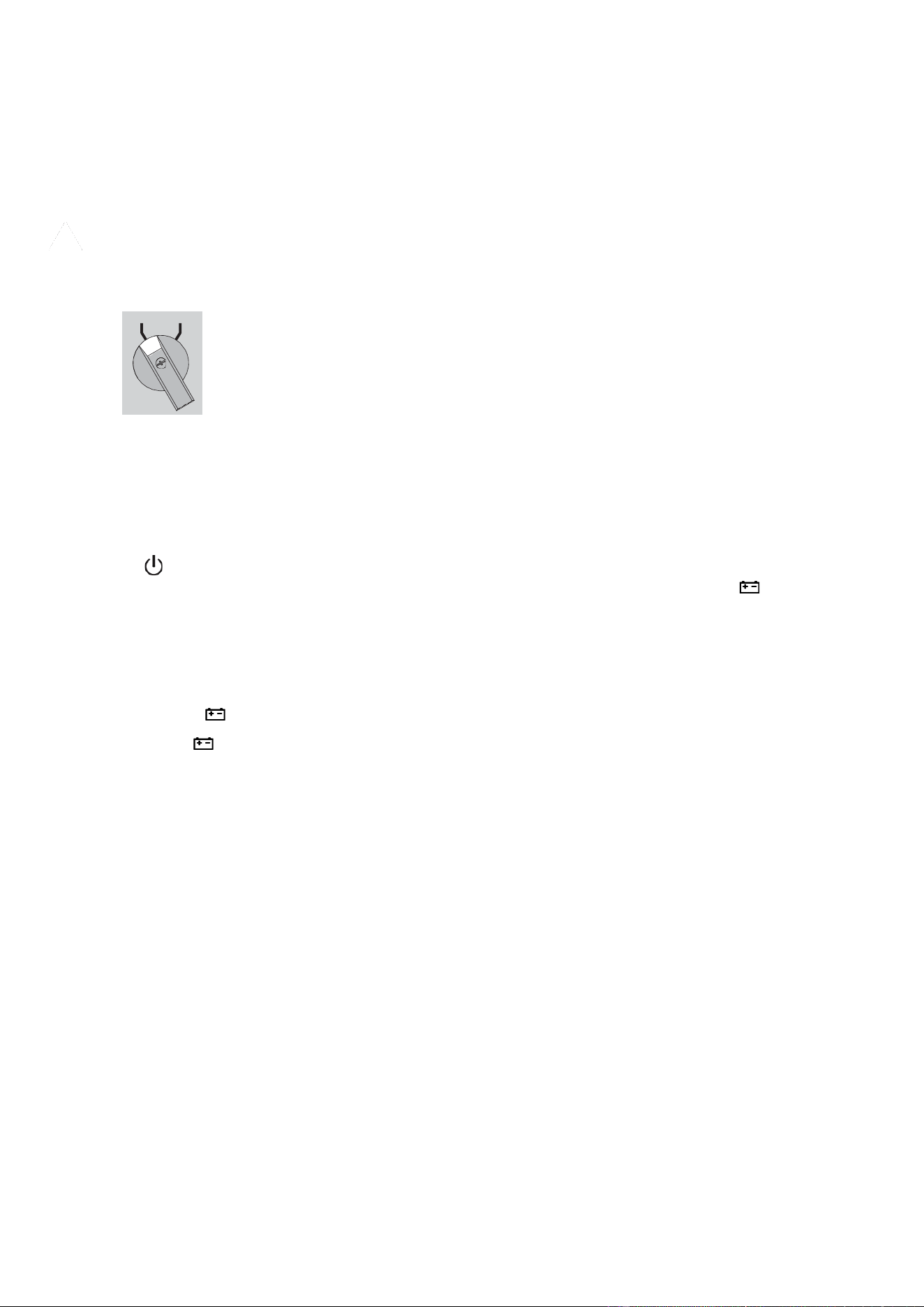
4. Set the upstream circuit breaker (not provided) to the “I” (On) position to switch on the utility power.
5. Verify that the "Bypass mode" red light of the MBP goes On, indicating that the load is now powered by
the AC source.
6. Set the Normal AC source switch of the MBP to the “I” (On) position.
7. Verify that the UPS is correctly powered (UPS display panel illuminates).
8. Press the UPS "ON" button to start the UPS.
9. Put the UPS in “Bypass mode” (“Control -> Go to bypass”).
10. Verify that the UPS is on Bypass mode by checking UPS display panel.
11. Verify that the "UPS mode" green light of the MBP goes On, indicating that the UPS output power is available on the MBP.
Important: do not continue to next step if the "UPS mode" green light of the MBP is still Off (the load will be lost).
12. Set the MBP manual Bypass switch to the "UPS" position: the "Bypass mode" red light of the MBP goes Off, indicating that
the load is now powered by the UPS.
13. Put the UPS in "Normal mode". (“Control -> Go back normal”)
14. Check that the UPS is in Normal mode by checking UPS display panel. The load is now protected by the UPS.
•
6.4
UPS shutdown
To shut down the UPS:
Press the button on the front panel for two seconds. confirmation message will appear. When confirmed, the UPS
starts to
beep and shows a status of "UPS shutting OFF...". The UPS then transfers to Standby mode, and the
indicator turns off.
UPS starts to beep and indicator is blinking. The UPS then transfers to Standby mode, and the indicator turns off.
6.5
Operating modes
The Eaton 9PX G2 front panel indicates the UPS status through the UPS indicators located above the LCD screen. LED
indicator:
Normal mode
When the green
symbol is illuminated, the UPS is providing protected AC power output. The LED bar is illuminated in static
blue. The UPS monitors and charges the batteries as needed and provides power protection to your
equipment. Optional High
Efficiency and Energy Saving settings minimize heat contribution to the rack environment. See user settings.
UPS BYPASS

Battery mode
When the UPS is operating during a power outage, the alarm beeps once every ten seconds and the indicator
illuminates
solid. The LED bar is flashing blue.
The necessary energy is provided by the battery.
When the utility power returns, the UPS transfers to Normal mode operation while the battery recharges.
If battery capacity
becomes low while in Battery mode, the audible alarm beeps faster.
This warning is approximate, and the actual time to shutdown may vary significantly; shutdown all applications on
connected
equipment due to imminent UPS shutdown.
When utility power is restored after the UPS shuts down, the UPS automatically restarts.
Low-battery warning
•
The indicator illuminates solid.
•
The audio alarm beeps every three seconds.
•
The LED bar illuminates red
The remaining battery power is low. Shut down all applications on the connected equipment because automatic UPS shutdown
is imminent.
Low-battery warning
•
The indicator blinking quickly.
•
The audio alarm beeps every 1.5 seconds.
The remaining battery power is low. Shut down all applications on the connected equipment because automatic UPS shutdown
is imminent.
End of battery backup time
•
LCD displays "End of backup time".
•
All the LEDs go OFF.
•
The audible alarm stops.
Bypass mode
In the event of a UPS overload or internal failure, the UPS transfers your equipment to utility power. Battery mode is not available
and your equipment is not protected; however, the utility power continues to be passively filtered by the UPS.
The by-pass indicator
illuminates in orange.
Depending on overload conditions, the UPS remains in Bypass mode for at least five seconds and will stay in this mode if three
transfers to Bypass occur within 20 minutes.
The UPS transfers to Bypass mode when:
•
the user activates Bypass mode through the front panel,
•
the UPS detects an internal failure,
•
the UPS has an overtemperature condition,
•
the UPS has an overload condition listed.
The UPS shuts down after a specified delay for overload conditions listed.
6.6
Return of AC input power
Following an outage, the UPS restarts automatically when AC input power returns (unless the restart function has been
disabled)
and the load is supplied again.
6.7
Configuring battery settings
Automatic battery test
Automatic battery tests are done every in constant charging mode and at each cycle in ABM® mode. The tests frequency
can be modified.
During the test, the UPS transfers to Battery mode and discharges the batteries for 10 seconds under load.
Battery mode is
not displayed and battery low alarm is not activated during a battery test.
The battery test may be postponed due to bad conditions, or failed if battery is not ok.
Low battery warning

During discharge, the low battery alarm is activated if the remaining runtime goes below 3 minutes or less than the
setting
capacity threshold (set to 20% by default by the Network Management card NM3).
This threshold can be modified.
External battery setting
The number of Extended Battery Module is automatically detected, or can be set manually in number of EBM or in Ah.
6.8
Deep discharge protection
This setting is recommended to avoid damaging the battery. Warranty is void if deep discharge protection is disabled.
Setting high efficiency mode
In High Efficiency mode, the UPS operates normally on Bypass and transfers to Online (or Battery) mode in less than 10
ms when
utility fails. Transfers to High Efficiency mode will be active after five minutes of Bypass voltage monitoring: if Bypass quality is
not in tolerance, then the UPS will remain in
Normal mode
.
Eaton recommends using the HE mode only to protect IT equipment.
To set the High Efficiency mode:
1.
Select Settings, In/Out settings, and High Efficiency mode.
2.
Select Enabled and Enter to confirm.
3.
The UPS transfers to High Efficiency mode after five minutes.

7
UPS maintenance
7.1
Equipment care
For the best preventive maintenance, keep the area around the equipment clean and dust free. If the atmosphere is very
dusty,
clean the outside of the system with a vacuum cleaner.
For full battery life, keep the equipment at an ambient temperature of 25 °C (77 °F).
The batteries are rated for a 3-5 year service life. The length of service life varies, depending on the frequency of usage and
ambient temperature (life divided by 2 each 10 °C above 25 °C).
If the UPS requires any type of transportation, verify that the UPS is turned off.
Batteries used beyond expected service life will often have severely reduced runtimes. Replace batteries at least every 4 years to
keep units running at peak performance.
Batteries runtime will be reduced at low temperature (below 10 °C).
7.2
Storing the equipment
If you store the equipment for a long period, recharge the battery every 6 months by connecting the UPS to utility power. The
internal batteries charge to 90% capacity in less than 3 hours. However, Eaton recommends that the batteries charge for 48 hours
after long-term storage.
Check the battery recharge date on the shipping carton label. If the date has passed and the batteries were never recharged, do
not use them. Contact your service representative.
7.3
When to replace batteries
Eaton9PX G2 batteries have an expected life span of 3-5 years.
Preventive Mode
After 4 years of operation, the UPS will provide a battery replacement notification reminding you that your batteries are nearing
the end of their useful life. You should take proactive steps to ensure you replace your batteries for optimal operation and
reliability.
Predictive Mode (ABM+)
Based on real UPS usage condition, a battery replacement warning (that includes the battery P/N) will be triggered at the most
appropriate time to help you keeping the UPS operating at its best performance. When battery he "Battery Age Status" will
change from "Healthy" to "Warning and Replace". You will have 2 months to replace your batteries for optimal operation and
reliability.
Contact your service representative to order new batteries.
Battery reference can be accessed through the LCD (Measurements > Battery).
180V battery reference is EBP-1805
240V battery reference is EBP-2003

7.4
UPS replacement with HotSwap MBP
UPS Removing (please follow the MANDATORY step below).
MBP6K208G2 and MBP6KIECG2:
UPS replacement must be performed by qualified person only.
1.
Put the UPS in “
Bypass mode
” (“Control -> Go to bypass”).
2.
Verify that the UPS is on Bypass mode by checking UPS display panel
3.
Set the MBP manual Bypass switch to “Bypass” position. The “Bypass mode” red light of the MBP goes
On, indicating that the load is supplied directly by AC source
4.
Switch the Normal AC source switch of the MBP to the “0” (Off) position and wait 30 seconds
5.
UPS stops, the UPS can now be disconnected, as described below:
•
First disconnect the I/O cord Set (1) from the MBP,
•
After opening the UPS I/O terminal blocks cover, check if hazardous voltage is no longer
present on UPS terminal blocks by using a voltage absence tester.
•
Disconnect the 2 power cables of the MBP I/O cord Set, and the MBP detection cable,
•
Replace the UPS.
Hazardous voltage and lost load risk: do not manipulate the MBP manual Bypass switch without UPS
connected via the I/O cord Set.
UPS BYPASS

MBP11K208G2:
UPS replacement must be performed by qualified person only.
1.
Put the UPS in “
Bypass mode
” (“Control -> Go to bypass”).
2.
Verify that the UPS is on Bypass mode by checking UPS display panel
3.
Set the MBP manual Bypass switch to "Bypass" position. The "Bypass mode" red light of the MBP goes
On,
indicating that the load is supplied directly by AC source
4.
Switch the Normal AC source switch of the MBP to the “0” (Off) position and wait 30 seconds
5.
UPS stops, the UPS can now be disconnected, as described below:
•
First lock the Normal AC source switch
of the MBP to the “0” (Off) position (the switch protection frame
can fit a cable tie or a metallic locker).
•
After opening the I/O terminal blocks cover of UPS, check if hazardous voltage is no longer present on
UPS terminal blocks by using a voltage absence tester.
•
Disconnect the MBP conduits, and the MBP detection cable
•
On both MBP conduits just disconnected from the UPS, link the internal wires together (line 1 and line
2 wires linked to ground wire)
•
Replace the UPS
Hazardous voltage and lost load risk: do not manipulate the MBP manual Bypass switch without UPS
connected
to the MBP power conduits
.
UPS BYPASS

Return to normal operation:
1.
Check that the new UPS is correctly connected to the MBP, as described below:
MBP6K208 and MBP6KIECG2:
•
After opening the UPS I/O terminal blocks cover, connect to UPS the 2 power cables, and the MBP
detection cable, of the MBP I/O cord Set
•
Connect the I/O cord Set connector to the MBP.
MBP11K208:
•
First check that the Normal AC source switch of the MBP is still locked to the "0" position
•
Remove the previously installed safety wires links on both MBP conduits
•
After opening the UPS I/O terminal blocks cover, connect to UPS the MBP conduits, and the MBP
detection cable
•
Unlock the Normal AC source switch of the MBP
2.
Set the Normal AC source switch of the MBP to the “I” (On) position.
3.
Verify that the UPS is correctly powered (UPS display panel illuminates)
4.
Press the UPS "ON" button to start the UPS
5.
Put the UPS in “
Bypass mode
” (“Control -> Go to bypass”)
6.
Verify that the UPS is on Bypass mode by checking UPS display panel
7.
Verify that the "UPS mode" green light of the MBP goes On, indicating that the UPS output power is
available on the MBP.
Important: do not continue to next step if the "UPS mode" green light of the MBP is still Off (the load
will be lost)
8.
Set the
MBP
manual Bypass switch to the
"UPS" position
: the
"Bypass mode" red light
of the MBP goes
Off, indicating that the load is now powered by the UPS
9.
Put the UPS in
“normal mode”
10.
Check that the UPS is in
Normal mode
by checking UPS display panel the load is now protected by the
UPS
UPS BYPASS

7.5
UPS maintenance with HotSwap MBP
Go to maintenance Bypass operation (please follow the MANDATORY steps below):
1.
Put the UPS in " Bypass mode"
2.
Verify that the UPS is on Bypass mode by checking UPS display panel
3.
Set the MBP manual Bypass switch to "Bypass" position. The "Bypass mode" red light of the MBP goes
On, indicating that the load is supplied directly by AC source
4.
Proceed to maintenance operations on UPS
Return to normal operation:
1.
Verify that the UPS is on Bypass mode by checking UPS display panel
2.
Verify that the
"UPS mode" green light
of the MBP is On, indicating that the UPS output power is
available on the MBP
Important:
do not continue to next step if the
"UPS mode" green light
of the MBP is Off (the load will be lost)
3.
Set the MBP manual Bypass switch to the
"UPS" position
: the
"Bypass mode" red light
of the MBP goes
Off, indicating that the load is now powered by the UPS
4.
Put the UPS in
"Normal mode"
5.
Check that the UPS is in Normal mode by checking UPS display panel the load is now protected by the
UPS.
•
7.6
Recycling the used equipment
Contact your local recycling or hazardous waste center for information on proper disposal of the used equipment.
eaton.com/recycling
Do not dispose the battery or batteries in a fire. Batteries may explode. Proper disposal of batteries is required. Refer to your
local codes for disposal requirements.
Do not open or mutilate the battery or batteries. Released electrolyte is harmful to the skin and eyes. It may be toxic.
Do not
discard the UPS or the UPS batteries in the trash. This product contains sealed, lead acid batteries and must be disposed
of properly. For more information, contact your local recycling/reuse or hazardous waste center.
Do not discard waste electrical or electronic equipment (WEEE) in the trash. For proper disposal, contact your local
recycling/reuse or hazardous waste center.
UPS BYPASS
UPS BYPASS

8
Troubleshooting
The Eaton 9PX G2 is designed for reliable, autonomous operation while providing you with notifications and alerts
whenever a potential operational or performance issue occurs.
Usually the alarms shown by the product do not mean that the output power is affected. Instead, they are preventive alarms
intended to alert the user.
•
Some alarms may be announced by a beep in a regular way. Example = "Battery low".
•
Faults are announced by a continuous beep and red LED.
8.1
Typical alarms and faults
To check the Event log or Fault log:
•
Press any button on the front panel display to activate the menu options.
•
Press the down button to select Event log or Fault log.
•
Scroll through the listed events or faults.
Use the following troubleshooting chart to determine the UPS alarm condition.
Conditions
Possible
cause
Action
Battery mode
LED is On.
1 beep every 10 seconds
A utility failure has occurred and the UPS is in
battery mode.
The UPS is powering the equipment with
battery power. Prepare your equipment for
shutdown.
Battery low
LED is On.
1 beep every 3 seconds
The UPS is in Battery mode and the battery is
running low.
This warning is approximate, and the
actual time to shutdown may vary
significantly.
Depending on the UPS load and number
of Extended Battery Modules (EBMs), the
"Battery Low" warning may occur before
the
batteries reach 20% capacity.
No battery
LED is On
Beep continuous
The batteries are disconnected.
Verify that all batteries are properly
connected. If the condition persists,
contact your service representative.
Battery fault
LED is On.
Beep continuous
The battery test is failed due to bad or
disconnected batteries.
Verify that all batteries are properly
connected. If the condition persists,
contact your service representative.
The UPS does not provide
the expected backup
time.
The batteries need charging or service.
Apply utility power for 48 hours to charge
the batteries. If the condition persists,
contact your service representative.
Bypass mode
LED is on.
An overload or a fault has occurred, or a
command has been received and the UPS is in
Bypass mode.
Equipment is powered but not protected
by
the UPS.
Check for one of the following alarms:
overtemperature, overload or UPS failure.
Power Overload
LED is On
Power requirements exceed the UPS capacity
(greater than 100% of nominal;
see “User Settings” for specific output
overload ranges).
Remove some of the equipment from the
UPS. The UPS continues to operate, but
may shut down if the load increases. The
alarm
resets when the condition becomes
inactive.
UPS overtemperature
LED is On
Beep continuous
The UPS internal temperature is too high or a
fan has failed. At the warning level, the UPS
generates the alarm but remains in the current
operating state. If the temperature rises
another 10°C, the UPS shuts down.
Clear vents and remove any heat sources.
Allow the UPS to cool. Ensure the airflow
around the UPS is not restricted. Restart
the
UPS. If the condition continues to
persist, contact your service
representative.
The UPS does not start
The input source is not connected correctly.
Check the input and battery connections.
The Remote Power Off (RPO) switch is active
or the RPO connector is missing.
If the UPS Status menu displays the
"Remote
Power Off" notice, deactivate the
RPO input.

Conditions
Possible
cause
Action
Input bad wiring / Output
bad wiring
LED is On
Beep continuous
Input/Output cables are not
connected to the
correct terminal
blocks.
Connect correctly the Input/Output cables.
MBP disconnected
The HotSwap MBP is no more
connected to
the UPS.
If the HotSwap MBP is connected to the
UPS,
check that the detection connector
is correctly plugged.
8.2
Silencing the alarm
Press the ESC (Escape) button on the front panel display to silence the alarm. Check the alarm condition and perform the
applicable action to resolve the condition. If the alarm status changes, the alarm beeps again, overriding the previous alarm
silencing.
8.3
Service and support
If you have any question or problem with the UPS, call Eaton or your local service representative in your country / region. Please
have the following information ready when you call for service:
•
Model number
•
Serial number
•
Firmware version number
•
Date of failure or problem
•
Symptoms of failure or problem
•
Customer return address and contact information
If repair is required, you will be given a Returned Material Authorization (RMA) number. This number must appear on the outside
of the package and on the Bill Of Lading (if applicable). Use the original packaging or request packaging from the Help Desk or
distributor. Units damaged in shipment as a result of improper packaging are not covered by warranty. A replacement or repair
unit will be shipped freight prepaid for all warrantied units.
For critical applications, immediate replacement may be available. Call the Help Desk for the dealer or distributor
nearest
you.
For US and Canada you can contact post-sales service support at: 1-(800)-356-5737.
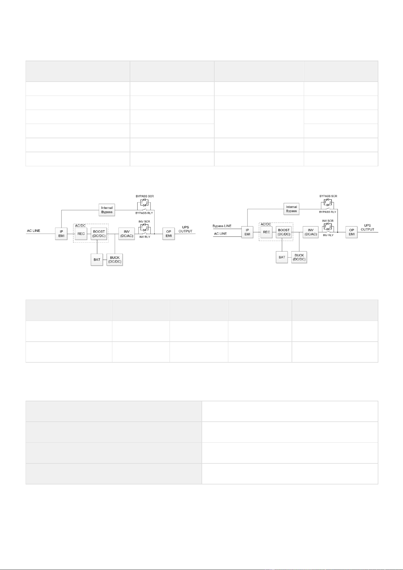
9
Specification and technical characteristics
9.1
UPS model list
Description
Catalog Number
Power
rating
Configuration
Eaton 9PX 3000 RT3U G2
9PX3K3UG2
3000W/3000VA
Rack / Tower
Eaton 9PX 5000 RT3U G2
9PX5KG2
4800W/5000VA
Rack / Tower
Eaton 9PX 6000 RT3U G2
9PX6KG2
4800W/5400VA (L6-30P)
6000W/6000VA(Hardwired)
Rack / Tower
Eaton 9PX 6000 IEC RT3U G2
9PX6KIECG2
Rack / Tower
Eaton 9PX 8000 RT4U G2
9PX8KG2
7600W/8000VA
Rack / Tower
Eaton 9PX 11000 RT4U G2
9PX11KG2
11000W/11000VA
Rack / Tower
Function block Diagram of 3~6K models
Function block Diagram of 8~11K models
9.2
Extended Battery Module model list
Model
Catalog
Number
Configuration
Battery
voltage
Used with
Eaton 9PX EBM 180V RT3U
G2
9PXEBM180RTG2
Rack / Tower
180Vdc
9PX3K3UG2, 9PX5KG2,
9PX6KG2, 9PX6KIECG2
Eaton 9PX EBM 240V RT3U
G2
9PXEBM240RTG2
Rack / Tower
240Vdc
9PX8KG2, 9PX11KG2
9.3
Electrical input
Default frequency
60Hz
Nominal frequency
50/60Hz
Frequency range
40-70Hz
Protective
class
Protective class I

Catalog
Number
Default input
(Voltage/Current)
Maximum Input
Current
Input nominal
voltages
Input voltage window
9PX3K3UG2
208V/21.14A
21.90A
200V, 208V, 220V,
230V, 240V
at 100% load: 176-276V
at ≤40% load: 100-276V
9PX5KG2
208V/25.54A
25.57A
9PX6KG2
208V/26.22A
208V/34.29A(Hardwired)
26.35A
9PX6KIECG2
34.51A
9PX8KG2
208V/41.78A
42.43A
9PX11KG2
208V/65.72A
65.72A
9.4
Electrical input connections
Catalog Number
Input connection
Input cable
9PX3K3UG2
L6-30P
L6-30P
9PX5KG2
9PX6KG2
L6-30P (Default)
Hardwired *
L6-30P
9PX6KIECG2
L6-30P (Default)
Hardwired *
L6-30P
9PX8KG2
Hardwired
Not provided
9PX11KG2
* User could remove the L6-30P to Hardwired wiring, to get more power rating (6000VA/6000W @208V)
a) Use the 40A upstream breaker, Select the appropriate size of input wire, refer to the chapter 4.4 UPS connection.
b) Select the “In/Out settings -> input wiring -> Hardwired” in the LCD menu.

9.5
Electrical output
All models
Normal mode
High Efficiency mode
Battery mode
Voltage regulation
±1%
±1%
Efficiency
3000VA: Up to 96.4%
5000/6000 VA: Up to 96.7%
8000/11000 VA: Up to 97.2%
3000VA: Up to 98.4%
5000/6000 VA: Up to 98.9%
8000/11000 VA: Up to 99.5%
3000VA: Up to 95.7%
5000/6000 VA: Up to 95%
8000/11000 VA: Up to
96.1%
Frequency regulation
Sync with line ±5% of nominal line frequency
(outside this range: ±0.5% of auto-selected nominal frequency)
±0.5% of auto-selected
nominal frequency
Nominal output
200/208/220/230/240V
Nominal Frequency
50Hz or 60Hz, autosensing or configurable as a frequency converter
Output overload
[102-125%] 10 mins
[125-150%] 30 sec
>150% 0.5s
[102-130%] 5mins
>130% 100ms
Short circuit current
limitation
Depend on the external fuse or breaker in the upstream of UPS
3000 VA: 45A
5000/6000 VA: 90A
8000 VA: 120A
11000 VA: 150A
< 5 cycles
Voltage waveform
sin wave
Harmonic distortion
< 1% THDV on linear load
< 5% THDV on non-linear load
Power Factor
up to 1
Load crest ratio
3:1
Transfer Time
Normal mode <-> Battery Mode: 0ms
Normal mode <-> Bypass Mode: 0ms
Normal mode -> High Efficiency Mode: 0ms
High Efficiency Mode -> Battery Mode: 10ms maximum
9.6
Electrical output connection
Catalog Number
Output connection
Output cable
9PX3K3UG2
9PX5KG2
9PX6KG2
Hardwired
(2) L6-30R Primary group
(1) L6-20R Group 1
(1) L6-20R Group 2
Not provided
9PX6KIECG2
Hardwired
(2) IEC10/16A + (2) IEC10A Primary group
(2) IEC10/16A + (2) IEC10A Group 1
(2) IEC10/16A + (2) IEC10A Group 2
(2) IEC10A 1.2m
9PX8KG2
9PX11KG2
Hardwired
(2) L6-30R Primary group
(1) L6-30R Group 1
(1) L6-30R Group 2
Not provided

9.7
Electrical Output Power
Model
Rated Output Voltage /
Maximum Current
VA / Watts
Power Factor
9PX3K3UG2
200
15.0
3000VA/3000W
PF=1.0
208
14.4
3000VA/3000W
PF=1.0
220
13.6
3000VA/3000W
PF=1.0
230
13.0
3000VA/3000W
PF=1.0
240
12.5
3000VA/3000W
PF=1.0
9PX5KG2
200
25.0
5000VA/4600W
PF=0.92
208
24.0
5000VA/4800W
PF=0.96
220
22.7
5000VA/5000W
PF=1.0
230
21.7
5000VA/5000W
PF=1.0
240
20.8
5000VA/5000W
PF=1.0
9PX6KG2/9PX6KIECG2
(Input wiring: L6-30P)
200
26.0
5200VA/4600W
PF=0.9
208
26.0
5400VA/4800W
PF=0.9
220
25.9
5700VA/5100W
PF=0.9
230
26.1
6000VA/5300W
PF=0.9
240
25.0
6000VA/5400W
PF=0.9
9PX6KG2/9PX6KIECG2
(Input wiring: Hardwired)
200
30.0
6000VA/6000W
PF=1.0
208
28.8
6000VA/6000W
PF=1.0
220
27.3
6000VA/6000W
PF=1.0
230
26.1
6000VA/6000W
PF=1.0
240
25.0
6000VA/6000W
PF=1.0
9PX8KG2
200
40.0
8000VA/7200W
PF=0.9
208
38.5
8000VA/7600W
PF=0.95
220
36.4
8000VA/8000W
PF=1.0
230
34.8
8000VA/8000W
PF=1.0
240
33.3
8000VA/8000W
PF=1.0
9PX11KG2
200
50.0
10000VA/10000W
PF=1.0
208
52.9
11000VA/11000W
PF=1.0
220
50.0
11000VA/11000W
PF=1.0
230
47.8
11000VA/11000W
PF=1.0
240
45.8
11000VA/11000W
PF=1.0
9.8
Battery
Internal
batteries
EBM
Specifications
3000/5000/6000VA: 180Vdc - 1x15x12V, 5Ah
8000/11000VA: 240Vdc - 1*20*12V, 9Ah
9PXEBM180RTG2: 180Vdc - 2x15x12V, 2x5Ah=10Ah
9PXEBM240RTG2: 240Vdc - 1*20*12V, 9Ah
Type
Sealed, maintenance-free, valve-regulated, lead-acid, with minimum 3-5 year float service life at 25°C
(77°F).
Monitoring
Advanced monitoring for earlier failure detection and warning ABM+
EBM battery
cable length
180V DC : 330mm
240V DC : 400mm

9.9
Battery Backup time
The following backup time values are given at 240V.
The battery backup time of 9PX3K3UG2 (mins)
Internal battery
+ EBM quantity
Output
Power
(W)
5%
10%
20%
30%
40%
50%
60%
70%
80%
90%
100%
Internal
3000
223.3
104.0
52.8
34.6
24.5
18.5
14.6
12.3
10.3
8.7
7.5
Internal +1*EBM
3000
768.4
348.9
184.3
124.8
91.8
71.8
58.2
49.5
42.3
36.7
32.2
Internal +2*EBM
3000
>1200
625.0
324.0
220.2
163.3
128.9
105.7
90.4
77.8
68.0
60.1
Internal +3*EBM
3000
>1200
936.3
473.2
319.7
236.9
187.5
154.3
132.6
114.5
100.4
89.1
Internal +4*EBM
3000
>1200
>1200
632.8
423.8
313.1
247.5
203.8
175.8
152.0
133.5
118.7
Internal +5*EBM
3000
>1200
>1200
803.6
532.8
391.9
309.2
254.5
219.9
190.3
167.2
148.8
Internal +6*EBM
3000
>1200
>1200
986.0
647.0
473.5
372.7
306.3
264.9
229.3
201.5
179.4
Internal +7*EBM
3000
>1200
>1200
1180.5
766.5
558.1
438.0
359.3
310.8
269.0
236.4
210.5
Internal +8*EBM
3000
>1200
>1200
>1200
891.4
645.7
505.1
413.6
357.6
309.3
271.8
242.0
Internal +9*EBM
3000
>1200
>1200
>1200
1021.8
736.4
574.3
469.3
405.3
350.4
307.8
274.0
Internal +10*EBM
3000
>1200
>1200
>1200
1157.7
830.2
645.4
526.3
453.8
392.1
344.2
306.4
Internal +11*EBM
3000
>1200
>1200
>1200
>1200
927.2
718.5
584.6
503.3
434.5
381.3
339.2
Internal +12*EBM
3000
>1200
>1200
>1200
>1200
1027.4
793.7
644.4
553.6
477.6
418.9
372.5
The battery backup time of 9PX5KG2 (mins)
Internal battery
+ EBM quantity
Output
Power
(W)
5%
10%
20%
30%
40%
50%
60%
70%
80%
90%
100%
Internal
5000
132.0
67.1
30.4
18.9
12.9
9.4
7.1
6.0
4.9
4.1
3.5
Internal +1*EBM
5000
442.5
229.7
113.3
73.0
52.2
39.6
31.4
26.7
22.4
19.1
16.5
Internal +2*EBM
5000
803.5
405.3
200.1
131.1
95.4
73.7
59.5
50.3
42.8
36.9
32.3
Internal +3*EBM
5000
>1200
595.8
290.1
190.6
139.5
108.7
88.4
75.0
64.1
55.6
48.9
Internal +4*EBM
5000
>1200
802.9
383.9
251.6
184.5
144.2
117.7
100.2
85.9
74.8
66.0
Internal +5*EBM
5000
>1200
1027.2
481.8
314.4
230.3
180.2
147.4
125.9
108.2
94.4
83.4
Internal +6*EBM
5000
>1200
>1200
584.2
378.9
277.1
216.7
177.5
151.9
130.7
114.2
101.1
Internal +7*EBM
5000
>1200
>1200
691.2
445.4
324.8
253.9
207.9
178.3
153.5
134.2
119.0
Internal +8*EBM
5000
>1200
>1200
802.9
513.8
373.7
291.7
238.8
205.1
176.6
154.5
137.0
Internal +9*EBM
5000
>1200
>1200
919.4
584.2
423.5
330.1
270.1
232.2
200.0
175.0
155.3
Internal +10*EBM
5000
>1200
>1200
1041.0
656.7
474.5
369.2
301.8
259.6
223.6
195.7
173.7
Internal +11*EBM
5000
>1200
>1200
1167.5
731.2
526.7
409.0
334.0
287.3
247.5
216.6
192.2
Internal +12*EBM
5000
>1200
>1200
>1200
807.9
580.0
449.5
366.6
315.4
271.6
237.7
211.0

The battery backup time of 9PX6KG2/9PX6KIECG2 (Input wiring: L6-30P) (mins)
Internal battery
+ EBM quantity
Output
Power
(W)
5%
10%
20%
30%
40%
50%
60%
70%
80%
90%
100%
Internal
5400
121.4
61.2
27.3
17.0
11.5
8.3
6.3
5.4
4.4
3.6
3.0
Internal +1*EBM
5400
406.8
210.9
103.3
66.5
47.2
35.8
28.2
24.0
20.1
17.1
14.7
Internal +2*EBM
5400
734.9
371.4
183.0
119.9
86.9
67.2
54.0
45.6
38.7
33.3
29.0
Internal +3*EBM
5400
1110.7
544.5
265.2
174.6
127.4
99.3
80.5
68.2
58.1
50.3
44.2
Internal +4*EBM
5400
>1200
731.4
350.5
230.5
168.7
132.0
107.5
91.3
78.1
67.9
59.8
Internal +5*EBM
5400
>1200
932.9
439.3
287.9
210.6
165.1
134.8
114.8
98.5
85.8
75.7
Internal +6*EBM
5400
>1200
1149.6
531.7
346.8
253.3
198.6
162.4
138.7
119.1
103.9
91.8
Internal +7*EBM
5400
>1200
>1200
628.0
407.2
296.9
232.6
190.3
162.8
139.9
122.2
108.1
Internal +8*EBM
5400
>1200
>1200
728.2
469.3
341.3
267.2
218.5
187.3
161.1
140.8
124.6
Internal +9*EBM
5400
>1200
>1200
832.5
533.1
386.6
302.3
247.1
212.0
182.4
159.5
141.3
Internal +10*EBM
5400
>1200
>1200
941.0
598.6
432.9
338.0
276.1
237.1
204.0
178.4
158.1
Internal +11*EBM
5400
>1200
>1200
1053.7
665.9
480.1
374.2
305.5
262.4
225.7
197.4
175.0
Internal +12*EBM
5400
>1200
>1200
1170.7
734.9
528.2
411.0
335.2
288.0
247.7
216.7
192.1
The battery backup time of 9PX6KG2/9PX6KIECG2(Input wiring: Hardwired) (mins)
Internal battery
+ EBM quantity
Output
Power
(W)
5%
10%
20%
30%
40%
50%
60%
70%
80%
90%
100%
Internal
6000
107.8
53.9
23.7
14.7
9.9
7.1
5.4
4.6
3.7
3.1
2.6
Internal +1*EBM
6000
361.4
187.8
91.6
58.6
41.4
31.2
24.5
20.9
17.4
14.8
12.7
Internal +2*EBM
6000
648.6
330.2
162.8
106.4
76.9
59.2
47.5
40.1
33.9
29.1
25.3
Internal +3*EBM
6000
973.5
482.4
236.1
155.3
113.2
88.0
71.2
60.2
51.2
44.3
38.8
Internal +4*EBM
6000
>1200
645.5
311.7
205.2
150.0
117.2
95.3
80.8
69.1
60.0
52.7
Internal +5*EBM
6000
>1200
820.2
390.0
256.2
187.4
146.8
119.7
101.8
87.2
75.9
66.9
Internal +6*EBM
6000
>1200
1007.0
471.2
308.3
225.5
176.7
144.4
123.1
105.6
92.1
81.3
Internal +7*EBM
6000
>1200
>1200
555.4
361.7
264.1
207.1
169.3
144.7
124.3
108.4
95.9
Internal +8*EBM
6000
>1200
>1200
642.7
416.4
303.5
237.8
194.5
166.5
143.1
125.0
110.6
Internal +9*EBM
6000
>1200
>1200
733.3
472.5
343.6
269.0
220.0
188.5
162.1
141.7
125.4
Internal +10*EBM
6000
>1200
>1200
827.2
529.9
384.3
300.5
245.7
210.8
181.3
158.5
140.4
Internal +11*EBM
6000
>1200
>1200
924.5
588.7
425.9
332.6
271.7
233.3
200.7
175.5
155.5
Internal +12*EBM
6000
>1200
>1200
1025.1
648.9
468.2
365.1
298.1
256.0
220.3
192.7
170.8

The battery backup time of 9PX8KG2 (mins)
Internal battery
+ EBM quantity
Output
Power
(W)
5%
10%
20%
30%
40%
50%
60%
70%
80%
90%
100%
Internal
8000
202.1
102.0
47.5
30.4
20.8
15.2
11.6
9.7
7.9
6.5
5.4
Internal +1*EBM
8000
440.6
218.4
106.0
68.7
48.7
36.9
29.0
25.1
20.9
17.7
15.2
Internal +2*EBM
8000
726.6
345.6
166.9
109.5
79.1
61.2
49.0
42.3
35.8
30.8
26.7
Internal +3*EBM
8000
1065.3
485.0
229.9
151.0
109.9
85.7
69.3
59.8
51.0
44.2
38.7
Internal +4*EBM
8000
>1200
638.2
295.6
193.5
141.0
110.5
89.8
77.5
66.4
57.8
50.9
Internal +5*EBM
8000
>1200
806.3
364.4
237.2
172.7
135.5
110.4
95.3
81.9
71.5
63.2
Internal +6*EBM
8000
>1200
990.4
436.7
282.2
205.0
160.8
131.3
113.2
97.5
85.3
75.5
Internal +7*EBM
8000
>1200
1191.2
512.6
328.7
238.0
186.5
152.3
131.3
113.2
99.2
87.9
Internal +8*EBM
8000
>1200
>1200
592.4
376.8
271.8
212.7
173.6
149.5
129.0
113.1
100.4
Internal +9*EBM
8000
>1200
>1200
676.2
426.6
306.3
239.3
195.1
168.0
145.0
127.2
112.9
Internal +10*EBM
8000
>1200
>1200
764.2
478.0
341.8
266.4
217.0
186.7
161.1
141.3
125.5
Internal +11*EBM
8000
>1200
>1200
856.4
531.3
378.2
294.0
239.2
205.7
177.3
155.6
138.2
Internal +12*EBM
8000
>1200
>1200
953.1
586.3
415.5
322.2
261.8
224.9
193.8
170.0
151.0
The battery backup time of 9PX11KG2 (mins)
Internal battery
+ EBM quantity
Output
Power
(W)
5%
10%
20%
30%
40%
50%
60%
70%
80%
90%
100%
Internal
11000
146.0
74.3
32.2
19.9
13.2
9.4
6.9
5.8
4.6
3.7
3.1
Internal +1*EBM
11000
313.4
160.7
74.7
46.9
32.6
24.1
18.5
16.1
13.1
10.9
9.3
Internal +2*EBM
11000
504.5
252.6
119.0
76.4
54.5
41.3
32.6
28.1
23.5
19.9
17.1
Internal +3*EBM
11000
722.0
350.4
164.1
106.2
76.8
59.0
47.2
40.6
34.2
29.3
25.5
Internal +4*EBM
11000
968.9
455.3
210.3
136.4
99.2
76.8
61.9
53.2
45.2
39.0
34.1
Internal +5*EBM
11000
>1200
568.1
257.9
167.1
121.8
94.7
76.8
66.0
56.3
48.8
42.9
Internal +6*EBM
11000
>1200
689.1
307.1
198.3
144.6
112.8
91.7
78.8
67.5
58.7
51.7
Internal +7*EBM
11000
>1200
819.0
358.0
230.2
167.8
131.0
106.7
91.7
78.7
68.6
60.6
Internal +8*EBM
11000
>1200
958.1
410.8
262.7
191.2
149.4
121.8
104.7
89.9
78.5
69.5
Internal +9*EBM
11000
>1200
1106.7
465.6
296.1
215.1
167.9
137.0
117.7
101.2
88.5
78.4
Internal +10*EBM
11000
>1200
>1200
522.4
330.2
239.3
186.7
152.3
130.9
112.6
98.5
87.4
Internal +11*EBM
11000
>1200
>1200
581.3
365.2
263.9
205.6
167.8
144.1
124.1
108.6
96.4
Internal +12*EBM
11000
>1200
>1200
642.4
401.1
288.9
224.9
183.4
157.4
135.6
118.7
105.4

9.10
Environmental and safety
Standards
IEC/EN 62040-1 Safety
IEC/EN 62040-2 Electromagnetic Compatibility EMC
IEC/EN 62040-3 Performance
FCC part 15 Class A
UL 1778 ENERGY STAR Program Requirements for Uninterruptible Power Supplies (UPSs)
Version 2.0
CSA-C22.2 No. 107.3
EMC (Emissions)
CISPR32 Class A
FCC part 15 Class A
IEC/EN 62040-2 C2
IEC/EN 61000-3-2 or IEC/EN 61000-3-12 Harmonicas
IEC/EN 61000-3-3 or IEC/EN 61000-3-11 Flickers
EMC (Immunity)
IEC 61000-2-2, (Low Frequency): 10V, 140-360Hz
IEC 61000-4-2, (ESD): 8 kV Contact Discharge / 15 kV Air Discharge
IEC 61000-4-3, (Radiated field): 10 V/m
IEC 61000-4-4, (EFT): 4 kV Power Port / 2 kV Network Port
IEC 61000-4-5, (Surges): 2 kV Differential Mode / 4 kV Common Mode / 1 kV Network Port
IEC 61000-4-6, (Electromagnetic field): 10 V
IEC 61000-4-8, (Conducted magnetic field): 30 A/m
IEC 61000-4-11, (Voltage Dips) Class 2
IEC 61000-4-12, (Ring Wave): 2 kV Differential Mode / 2kV Common Mode
UPS enclosure IP rating
IP20
Earthing
system
This UPS can be connected to TN, TT, IT electrical supply system, same system is supplied
to the load.
Overvoltage
Category
Category II
Pollution degree
PD2
Operating temperature
0 to 40 °C (32 to 104 °F)
Operating altitude
Up to 3,000 meters (9,842ft) above sea level (without derating).
Relative humidity
0 to 95 % (without condensation)
Storage
temperature
0°C to 40°C (32°F to 104°F) with battery
-25°C to 55°C (-13 °F to 131 °F) without battery
Transit
altitude
Up to 10,000 meters (32,808 ft) above sea level
Transit temperature
-25°C to 55°C (-13 °F to 131 °F)
Audible noise
Line mode (load < 66%, T<30°C) :
11000/8000 VA < 38 dB
6000/5000/3000 VA < 38 dB
Batt. Mode :
11000/8000 VA < 59 dB
6000/5000/3000 VA < 49 dB

1
Glossary
Backup time Time during which the load can be supplied by the UPS operating on
battery power.
Low-battery warning This is a battery-voltage level indicating that battery power is low and that the user
must
take action before the UPS shuts down.
Load Devices or equipment connected to the UPS output.
Normal mode (double conversion) The normal UPS operating mode in which the AC source supplies the UPS which, in turn,
provides AC power to the connected loads. (after electronic double conversion).Normal
AC source Normal source of power for the UPS
.
OVL Overload. When the load exceeds 100% of the maximum load of the UPS.
UPS Uninterruptible Power System.
Relay contacts Contacts supplying information to the user in the form of signals.
Bypass AC source Source supplying the bypass line. The equipment can be transferred to the by-pass
line if an overload occurs on the UPS output, for maintenance or in the event of a
malfunction.
EBM Extended Battery Module
Frequency converter Operating mode used to convert the AC power frequency between the UPS
input and output (50Hz -> 60Hz or 60Hz -> 50Hz).
HE Mode
Operating mode by which the load is supplied directly by the AC source if it is
within the
tolerances defined by the user. This mode reduces the consumption of
electrical power.