INLP28SSV
Installation Instructions
Use and Care Information
Instructions d'installation
Utilisez et d'entretien
Instrucciones de instalación
Información de uso y cuidado
INCA LUX PREMIUM
A
B

2
CONTENTS
Section Page
Important safety instructions 3
Range Hood dimensions 6
Installation height requirements 7
Parts 8
Tools needed 10
Ducted venting method options 11
Mounting range hood
12
Choose Your Ducting Method
16
Connecting electricity
19
Operating the controls
21
Faber Cloud App
27
Remote control
28
Cleaning stainless steel
28
Caring for lters
29
Replacing lighting
30
Wiring diagram
31
Warranty
32

3
IMPORTANT SAFETY INSTRUCTIONS
READ AND SAVE THESE INSTRUCTIONS BEFORE YOU START
INSTALLING THIS RANGE HOOD
WARNING: - TO REDUCE THE RISK OF A RANGE TOP GREASE FIRE:
a) Never leave surface units unattended at high settings. Boilovers cause smoking and
greasy spillovers that may ignite. Heat oils slowly on low or medium setting.
b) Always turn hood ON when cooking at high heat or when ambeing food (i.e. Crepes
Suzette, Cherries Jubilee, Peppercorn Beef Flambé).
c) Clean ventilating fans frequently. Grease should not be allowed to accumulate on fan or
lter.
d) Use proper pan size. Always use cookware appropriate for the size of the surface element.
WARNING: - TO REDUCE THE RISK OF INJURY TO PERSONS IN THE EVENT OF A RANGE
TOP GREASE FIRE, OBSERVE THE FOLLOWING*:
a) SMOTHER FLAMES with a close-tting lid, cookie sheet, or metal tray, then turn off the
burner. BE CAREFUL TO PREVENT BURNS. If the ames do not go out immediately
EVACUATE AND CALL THE FIRE DEPARTMENT.
b) NEVER PICK UP A FLAMING PAN - You may be burned.
c) DO NOT USE WATER, including wet dishcloths or towels - a violent steam explosion will
result.
d) Use an extinguisher ONLY if:
1. You know you have a Class ABC extinguisher, and you already know how to operate
it.
2. The re is small and contained in the area where it started.
3. The re department is being called.
4. You can ght the re with your back to an exit.
* Based on "Kitchen Firesafety Tips" published by NFPA
WARNING - TO REDUCE THE RISK OF FIRE OR ELECTRIC SHOCK, do not use this fan with
any solid-state speed control device.
WARNING - TO REDUCE THE RISK OF FIRE, ELECTRICAL SHOCK, OR INJURY TO PERSONS,
OBSERVE THE FOLLOWING:
1. Use this unit only in the manner intended by the manufacturer. If you have any questions,
contact the manufacturer.
2. Before servicing or cleaning unit, switch power off at service panel and lock the service
disconnecting means to prevent power from being switched on accidentally. When the
service disconnecting means cannot be locked, securely fasten a prominent warning
device, such as a tag, to the service panel.
CAUTION: For General Ventilating Use Only. Do Not Use To Exhaust Hazardous or Explo-
sive Materials and Vapors.
WARNING - TO REDUCE THE RISK OF FIRE, ELECTRICAL SHOCK, OR INJURY TO PERSONS,
OBSERVE THE FOLLOWING:
1. Installation Work And Electrical Wiring Must Be Done By Qualied Person(s) In Accor-
dance With All Applicable Codes And Standards, Including Fire-Rated Construction.
2. Sufcient air is needed for proper combustion and exhausting of gases through the
ue (chimney) of fuel burning equipment to prevent backdrafting. Follow the heating
equipment manufacturer's guideline and safety standards such as those published by
the National Fire Protection Association (NFPA), and the American Society for Heating,
Refrigeration and Air Conditioning Engineers (ASHRAE), and the local code authorities.

4
ALL WALL AND FLOOR OPENINGS WHERE THE RANGE HOOD IS INSTALLED
MUST BE SEALED.
This Range Hood requires at least 24" of clearance between the bottom of the Range
Hood and the cooking surface or countertop. This hood has been approved by UL at this
distance from the cooktop.
This minimum clearance may be higher depending on local building codes. For gas cooktops
and combination ranges, a minimum of 30" is recommended and may be required.
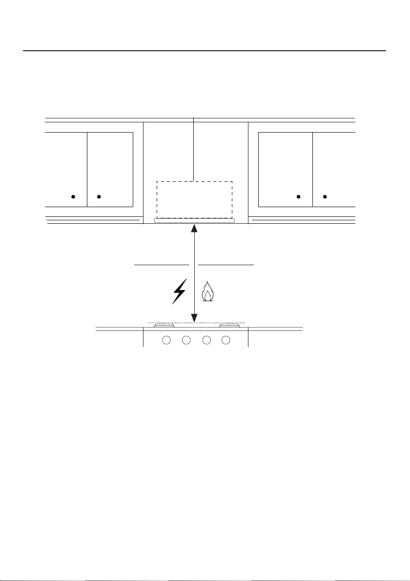
Overhead cabinets on both sides of this unit must be a minimum of 18" above the cooking
surface or countertop. Consult the cooktop or range installation instructions given by the
manufacturer before making any cutouts.
MOBILE HOME INSTALLATION The installation of this Range Hood must conform to the
Manufactured Home Construction and Safety Standards, Title 24 CFR, Part 3280 (formerly
Federal Standard for Mobile Home Construction and Safety, Title 24, HUD, Part 280). See
Electrical Requirements"
• Venting system MUST terminate outside the home.
• DO NOT terminate the ductwork in an attic or other enclosed space.
• DO NOT use 4" laundry-type wall caps.
• Flexible-type ductwork is not recommended.
• DO NOT obstruct the ow of combustion and ventilation air.
• Failure to follow venting requirements may result in a re.
WARNING
!
VENTING REQUIREMENTS
Determine which venting method is best for your application. Ductwork can extend either
through the wall or the roof.
The length of the ductwork and the number of elbows should be kept to a minimum to
provide efcient performance. The size of the ductwork should be uniform. Do not install
two elbows together. Use duct tape to seal all joints in the ductwork system. Use caulking
to seal exterior wall or oor opening around the cap.
Flexible ductwork is not recommended. Flexible ductwork creates back pressure and air
turbulence that greatly reduces performance.
Make sure there is proper clearance within the wall or oor for exhaust duct before making
cutouts. Do not cut a joist or stud unless absolutely necessary. If a joist or stud must be cut,
then a supporting frame must be constructed.
WARNING - To Reduce The Risk Of Fire, Use Only Metal Ductwork.
CAUTION - To reduce risk of re and to properly exhaust air, be sure to duct air outside
– Do not vent exhaust air into spaces within walls or ceilings or into attics, crawl spaces,
or garages.
Cold Weather installations
An additional back draft damper should be installed to minimize backward cold air ow and a nonme-
tallic thermal break should be installed to minimize conduction of outside temperatures as part of the
vent system. The damper should be on the cold air side of the thermal break. The break should be as
close as possible to where the vent system enters the heated portion of the house.
3. When cutting or drilling into wall or ceiling, do not damage electrical wiring and other
hidden utilities.
4. Ducted fans must always be vented to the outdoors.

5
ELECTRICAL REQUIREMENTS
A 120 volt, 60 Hz AC-only electrical supply is required on a separate 15 amp fused circuit.
A time-delay fuse or circuit breaker is recommended. The fuse must be sized per local
codes in accordance with the electrical rating of this unit as specied on the serial/rating
plate located inside the unit near the eld wiring compartment.
• Electrical ground is required on this Range Hood.
• If cold water pipe is interrupted by plastic, nonmetallic gaskets or other
materials, DO NOT use for grounding.
• DO NOT ground to a gas pipe.
• DO NOT have a fuse in the neutral or grounding circuit. A fuse in the neutral
or grounding circuit could result in electrical shock.
• Check with a qualied electrician if you are in doubt as to whether the Range
Hood is properly grounded.
• Failure to follow electrical requirements may result in a re.
WARNING
!

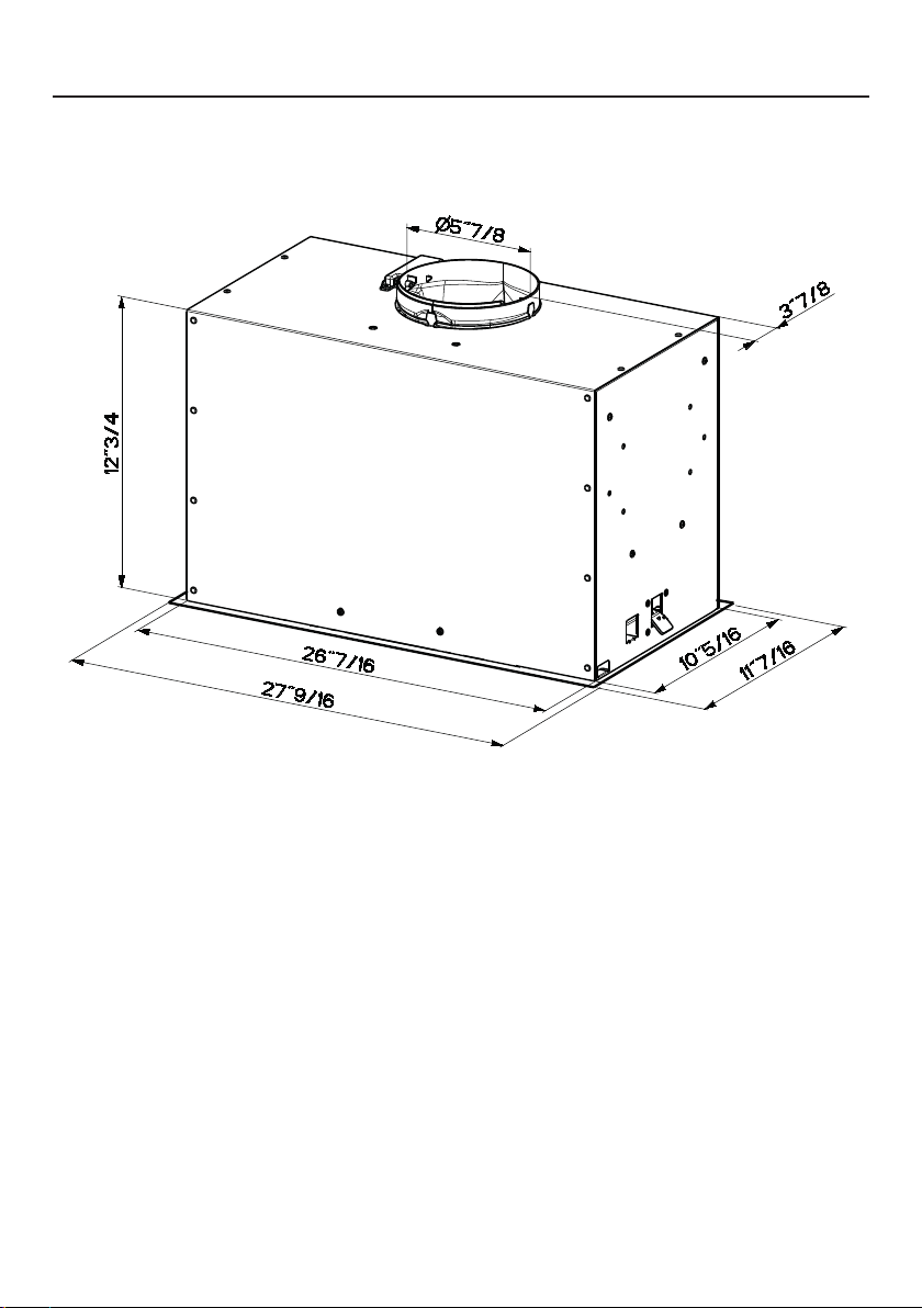
6
RANGE HOOD DIMENSIONS
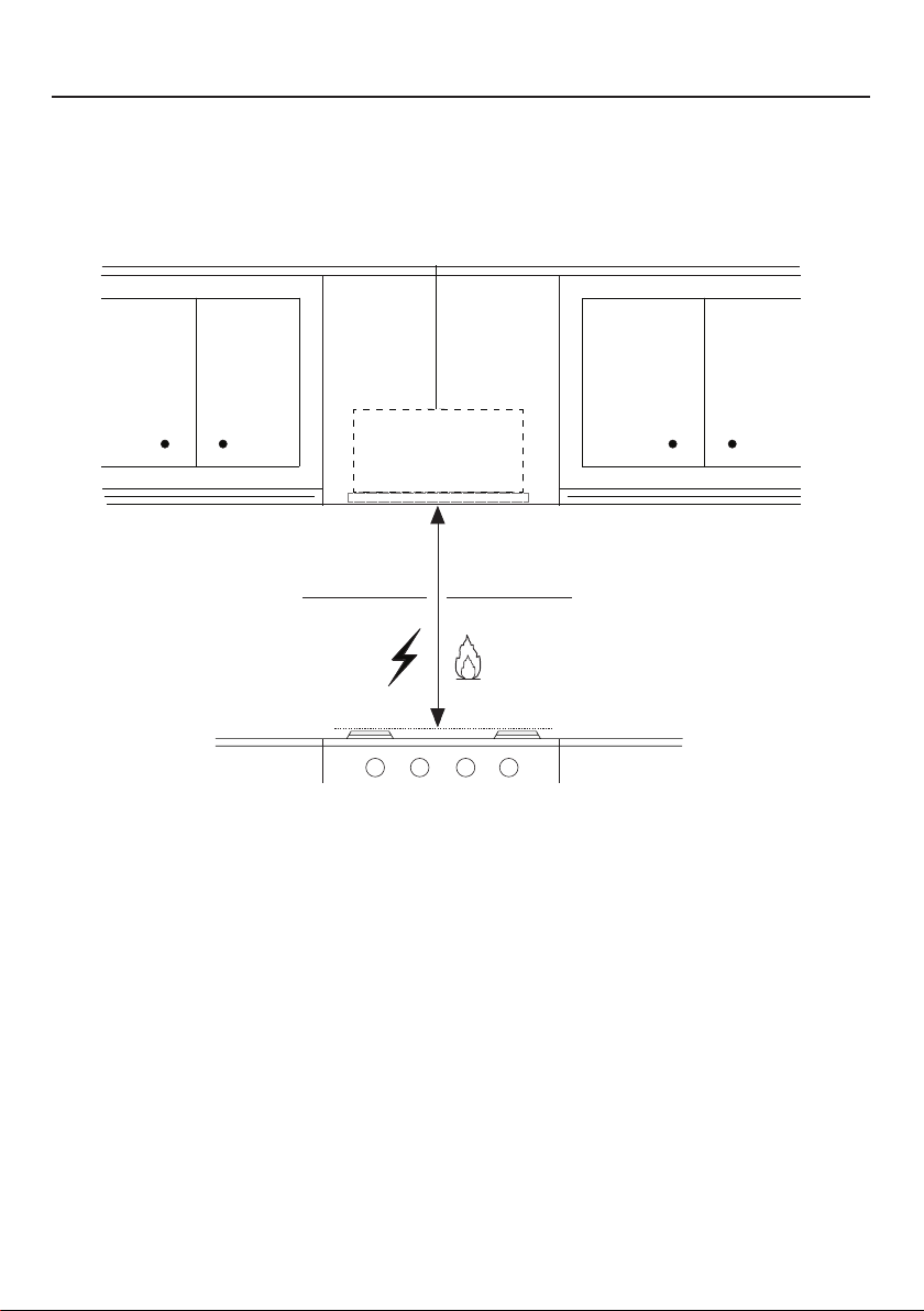
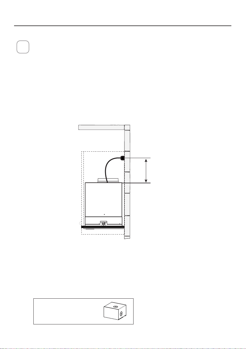
7
MIN. 24" OVER ELECTRIC / MIN. 30" OVER GAS
INSTALLATION HEIGHT REQUIREMENTS
Min. 24" Min. 30"

8
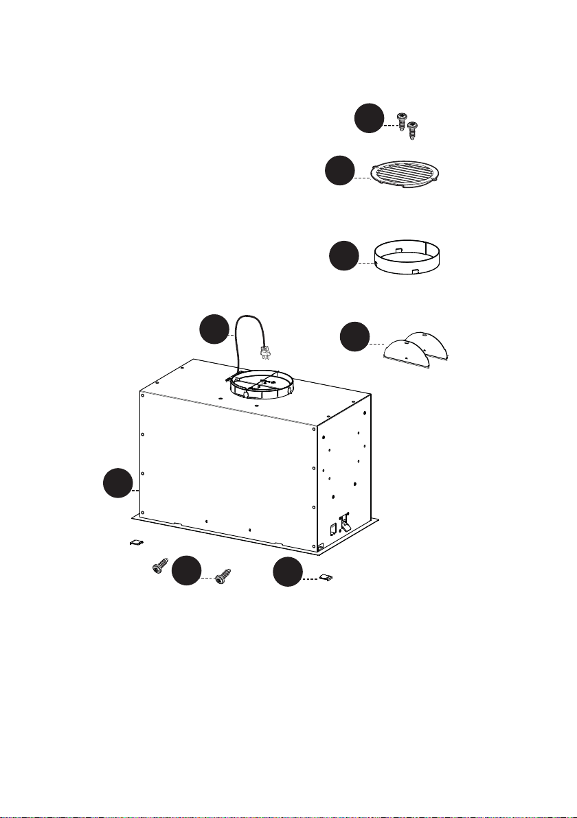
PARTS
REF. PART
A
Hood body – Includes Controls, Light, Motor, Filters
1
B
Power cord
1
C
Damper Flap
2
D
Damper ring
1
E
Recirculating grill cover
1
F
Cover
2
REF. PART
G
Screws 1/8" x 3/8"
4
PARTS INCLUDED
9
A
B
C
A
B
H1
D
P
E
F
G
G
10
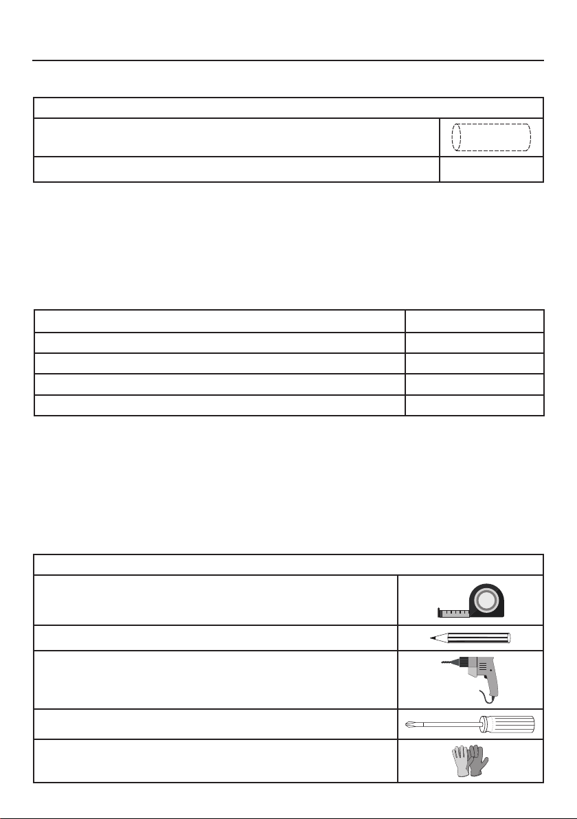
PARTS NEEDED
PARTS (cont.)
PART
6" Round Metal Ductwork
Wall Cap/Roof Cap Needs to be purchased separately
TOOLS NEEDED
TOOL
Tape Measure
Pencil
Electric Drill with 5/16" Drill Bit
Phillips Screwdriver
Work gloves
ACCESSORIES AVAILABLE
ACCESSORY SKU#
CHARCOAL FILTER KIT FILTER1
CHARCOAL FILTER KIT WASHABLE LONG LASTING FILTER1LL2
FIXED WIRING BOX WIREBOX
REMOTE CONTROL REMORIG

11
DUCTED VENTING METHOD OPTIONS
DUCTED WITH 6" ROUND OUTLET:
– Vertical
– Horizontal
NON DUCTED - RECIRCULATION OPTION
Requires purchase of
Activated Charcoal
Accessory
Horizontal
Vertical
6"
12
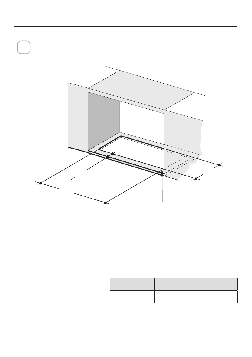
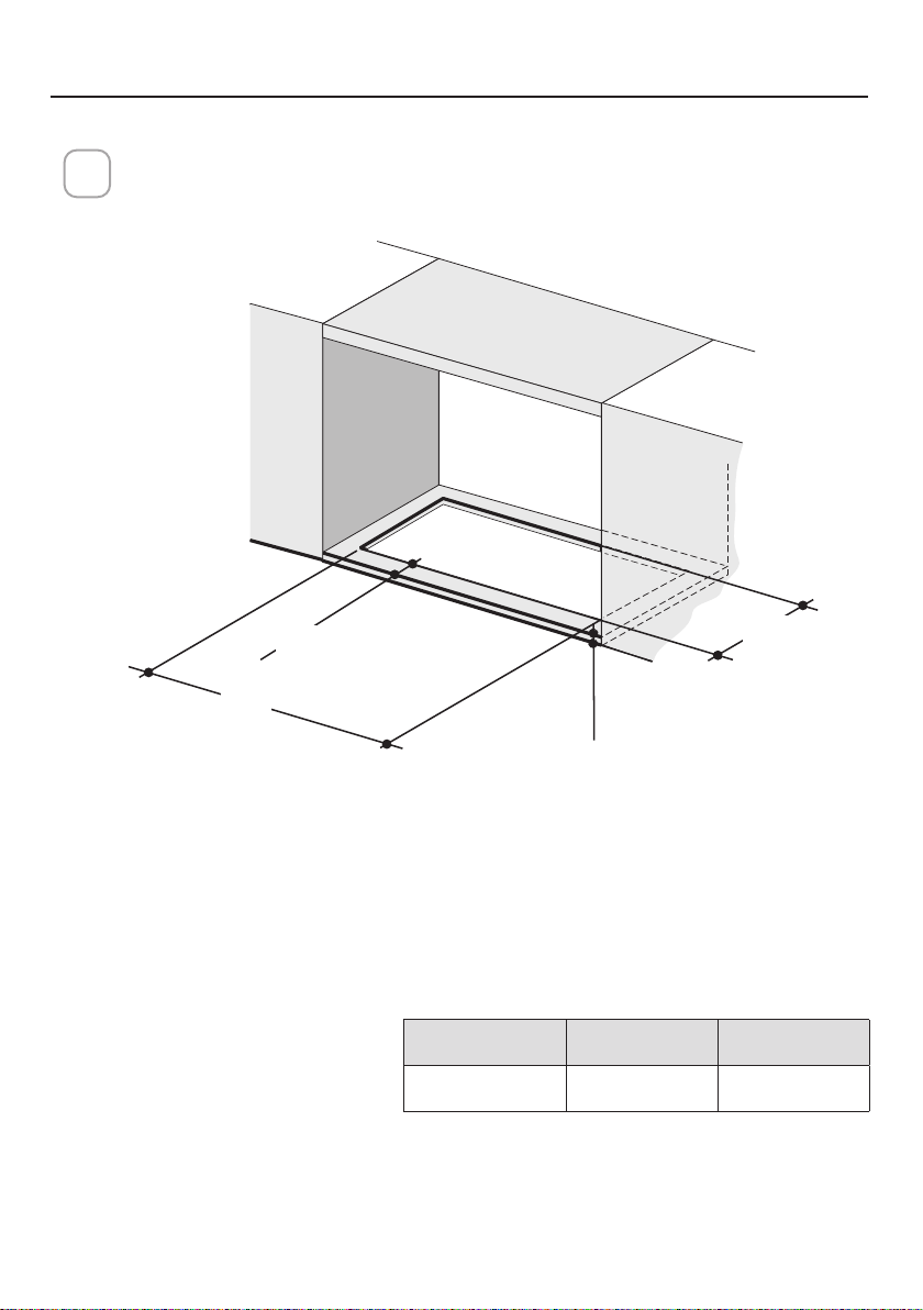
Cut out the opening in the underside of the cabinet as shown in figure
below.
1
MOUNTING RANGE HOOD
X
Y
Min.13/16
"
Min. 3/4
"
Model X Y
28" 26 9/16" 10 7/16"
Deep
Thickness
13
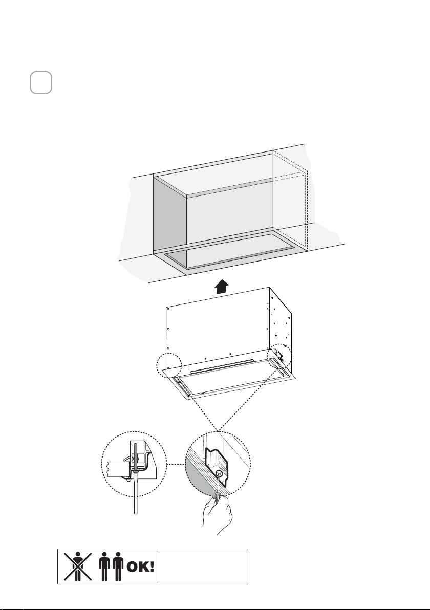
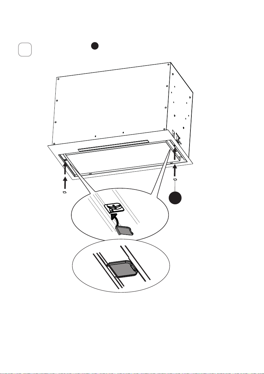
Install the Insert Hood into the cabinet opening, and fully engage the spring-
loaded Side Mount Clips onto the cabinet wood base.
Next from underneath the Insert as shown in Figure A, locate the screw in
each of the Side Mount Clips.
To lock the Insert Hood into position, tighten the screw for each of two Side
Mount Clips.
2
A
2x
Two people may
be required for
installation.

14
Insert the Cover
F
in each of the two screws openings as shown
3
B
2x
F
15
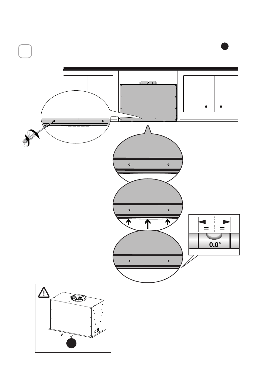
If the Hood is not levelled in the center part, attach the two screws
G
as
shown below
4
A
B
G
16
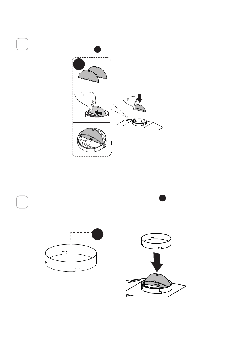
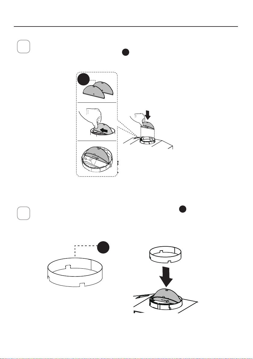
Break the 4 pre-cutting pieces and install the Ring
D
included with the
Range Hood before connecting to the ductwork.
2
Ducted Venting Installation
1
Install the 2 Damper flap
C
included with the Range Hood as shown.
CHOOSE YOUR DUCTING METHOD
D
C

17
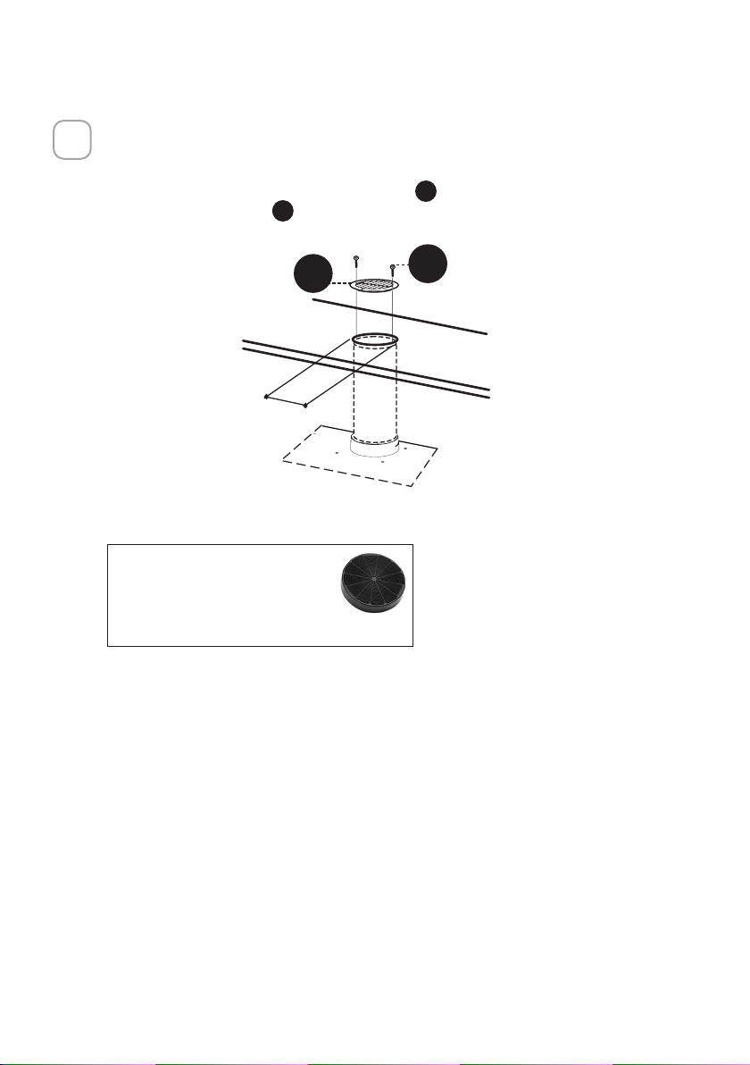
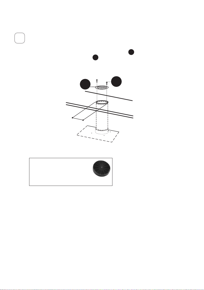
Install Roof or Wall Cap purchased separately.
Connect the 6" metal ductwork to the Roof or Wall Cap and then attach
ductwork.
3
18
Non-Ducted Recirculation Option
1
For Non-Ducted Recirculation venting route the ductwork to a location above
the hood where the discharge is vented back into the room.
Use the included Recirculation Vent Grill
E
to cover the opening. Secure the
grill with the 2 screws
G
provided in the Install Kit.
Required Charcoal Filter kit sku
#FILTER1
Durable charcoal filter kit sku
#FILTER1LL2
(purchased separately)
´
E
G
19
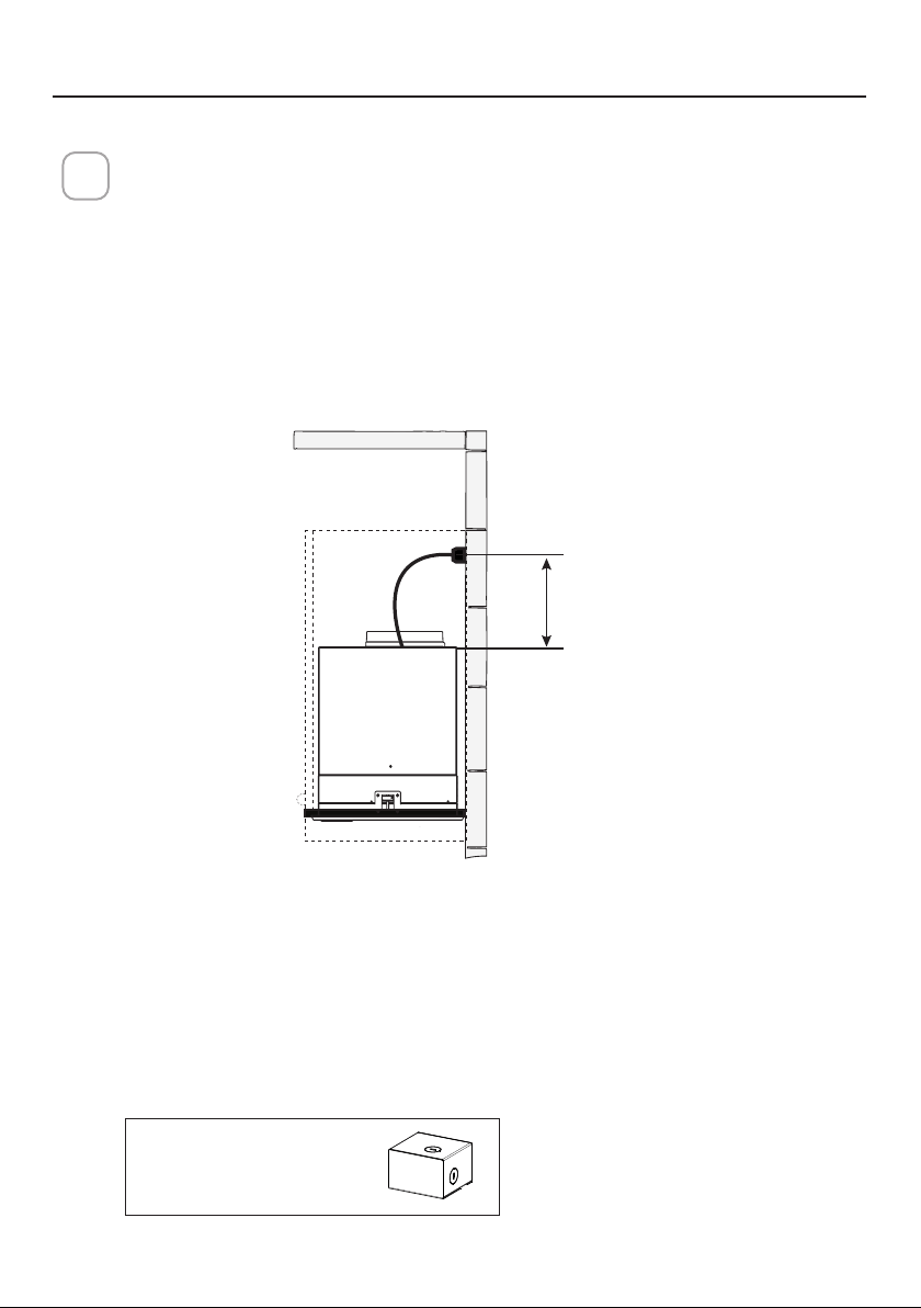
CONNECTING ELECTRICITY
ELECTRICAL INSTALLATION WITH CONNECTION CABLE
GROUNDING INSTRUCTIONS This appliance must be grounded. In the event of an
electrical short circuit, grounding reduces the risk of electric shock by providing an
escape wire for the electric current. This appliance is equipped with a cord having a
grounding wire with a grounding plug. The plug must be plugged into an outlet that
is properly installed and grounded.
WARNING - Improper grounding can result in a risk of electric shock.
Consult a qualified electrician if the grounding instructions are not completely un-
derstood, or if doubt exists as to whether the appliance is properly grounded.
Do not use an extension cord. If the power supply cord is too short, have a qualified
electrician install an outlet near the appliance.
1
WARNING - "The supply cord shall be accessible for inspection after installation".
Max. 33 7/16”
Direct Connect Wiring Box
Accessory sku # WIREBOX
(purchased separately)
ELECTRICAL INSTALLATION WITH OPTIONAL WIRING BOX
For Permanent wiring Installation-Use only with Listed Range Hood Wiring Box kit
sku # WIREBOX, manufactured by Faber
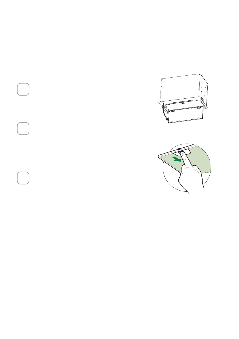
20
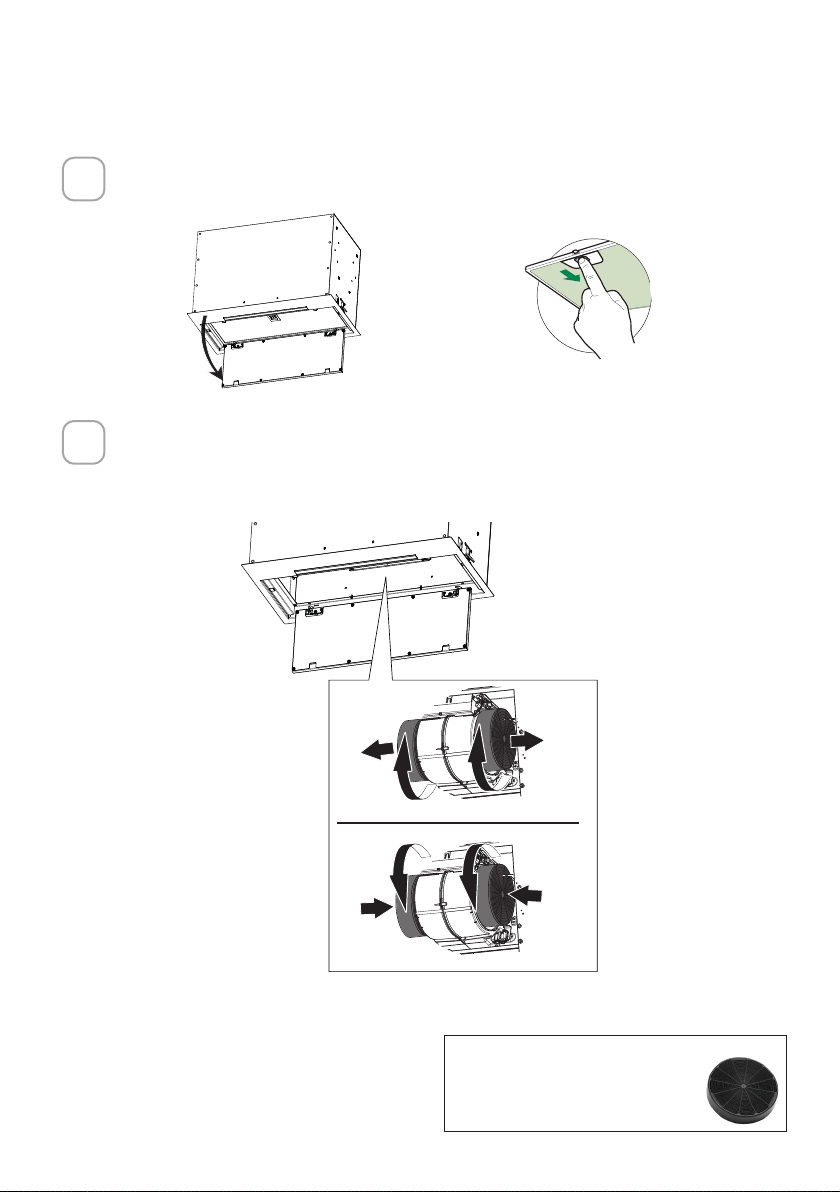
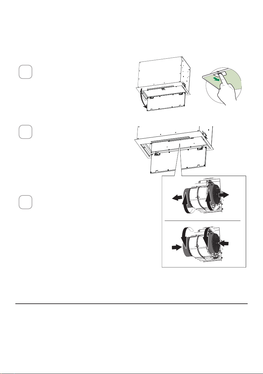
Open the Panel by pulling it down. Remove the grease lter, pushing the
lever towards the back of the unit while pulling downward.
Attach each charcoal filter to the black grid on each side of the blower.
Press the charcoal filter tightly to the black grid on the blower side and
rotate the filter clockwise (towards the front of the insert hood) until it locks
into place. Turn counterclockwise (towards the back of the insert hood) to
remove.
Required Activated Charcoal Filter
Accessory - sku sku #FILTER1 or
#FILTER1LL2
FOR NON-DUCTED RECIRCULATION OPTION
1
2
ace
W
W
21
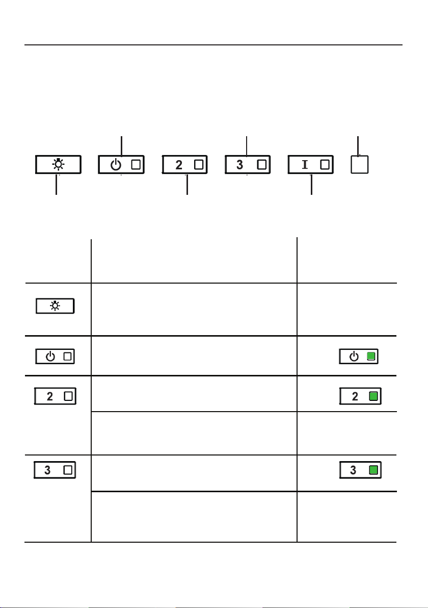
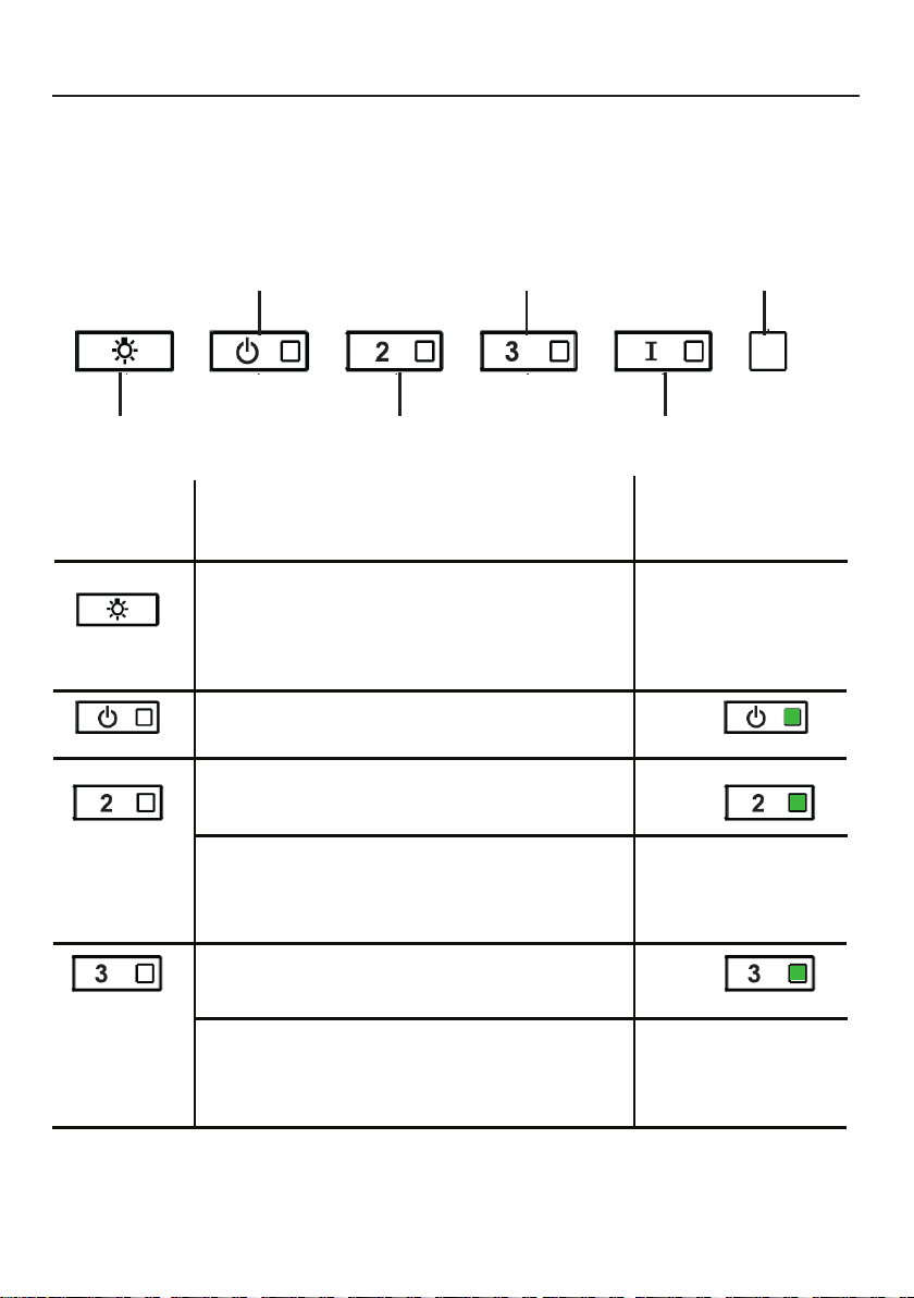
OPERATING THE CONTROLS
FOR BEST RESULTS
Start the Range Hood several minutes before cooking to develop proper
airflow. Allow the Range Hood to operate for several minutes after cooking
is complete to clear all smoke and odors from the kitchen.
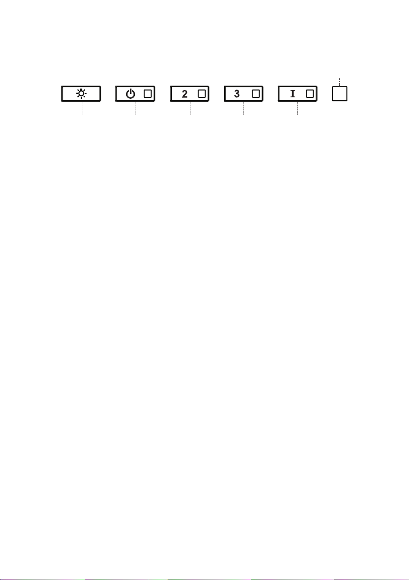
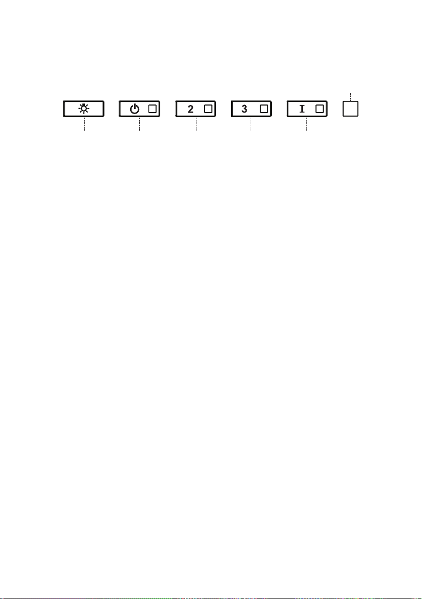
A - LIGHTS
B - POWER
C - SPEED 2
D - SPEED 3
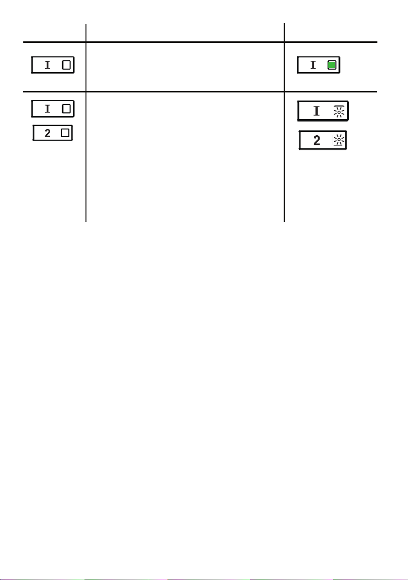
E - INTENSIVE
F - LED
A - LIGHTS - The lights have 3 levels - high, medium,
off - press the light button to change the levels.
It is possible to change the intensity of the light
cyclically. Using longseparate presses, it is possible to
vary the tone of the light between"warm" and "cold".
BUTTON FUNCTION INDICATOR
B - POWER - A quick press turns the motor on/off at
speed one
C - SPEED 2 - A quick press turns the motor on at
speed two
All LED’s flash twice
(alarm activated). All
LED’s lit for 1 second
(alarm deactivated)
D - SPEED 3 - A quick press turns the motor on at
speed three
Reset Grease Filter and / or Charcoal Filter Alarm -
A long press with the motor and lights off to reset the
filter wash alarms
All LED’s flash 3 times
Activate / Deactivate charcoal filter alarm - A
long press with the lights on and motor off will
activate or deactivate the charcoal alarm.
22
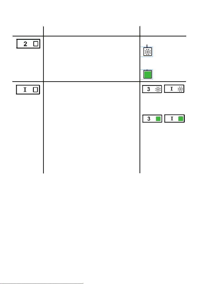
E - INTENSIVE LEVEL 1 - A quick press will
operate intensive speed level 1 for 6 minutes.
BUTTON FUNCTION INDICATOR
Grease Filter Alarm - If the speed two and
intensive buttons are lit, this means the
Grease Filter saturation alarm is activated
and the grease filters should be washed. The
alarm turns on after 100 hours of operation.
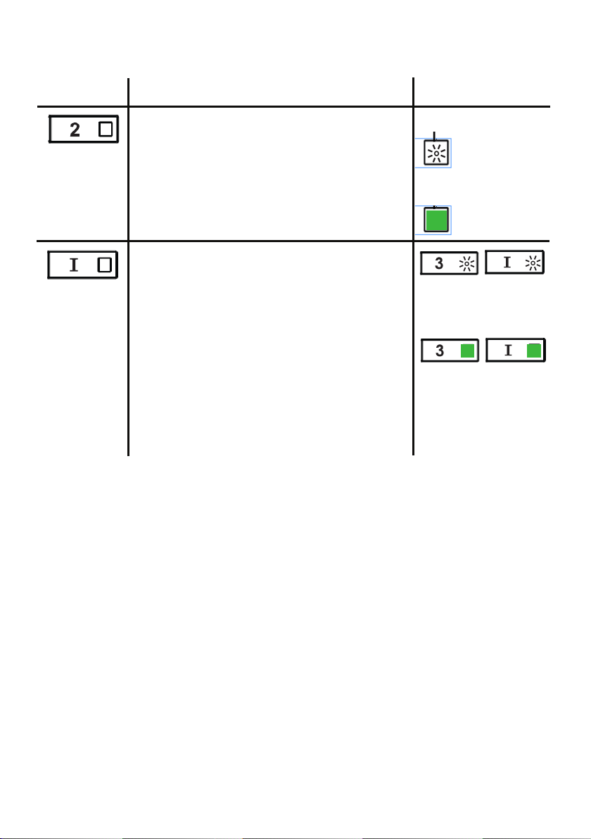
Charcoal Filter Alarm - if the alarm is
activated, the speed two and intensive lights
will blink. This means the Charcoal filters
should be replaced AND the grease filters
should be washed. The charcoal filter alarm
turns on after 200 hours of operation.

23
WI-FI INFORMATION
This device complies with part 15 of the FCC Rules. Operation is subject to the
following two conditions: (1) This device may not cause harmful interference, and
(2) this device must accept any interference received, including interference that
may cause undesired Operation.
Note: This equipment has been tested and found to comply with the limits for
a Class B digital device, pursuant to Part 15 of the FCC Rules. These limits are
designed to provide reasonable protection against harmful interference in a
residential installation. This equipment generates, uses and can radiate radio
frequency energy and, if not installed and used according to the instructions,
can cause harmful interference to radio communications. However, there is no
guarantee that interference will not occur in a particular installation.
If this equipment causes harmful interference to radio or television reception, which
can be determined by turning the equipment off and on again, the user is invited to
try to correct the interference by taking one or more of the following measures:
• Reorient or reposition the receiving antenna.
• Increase the separation between the equipment and the receiver.
• Connect the equipment to an outlet on a circuit other than the one to which the
receiver is connected.
• Consult your dealer or an experienced radio/TV technician for assistance.
Modifications to this product not authorized by Faber may invalidate
electromagnetic compatibility (EMC) and wireless compliance and deny permission
to use the product.
This product demonstrated EMC compliance under conditions that included the use
of compliant peripheral devices and shielded cables between system components.
It is important to use compliant peripherals and shielded cables between system
components to reduce the possibility of causing interference to radios, televisions,
and other electronic devices.
Exposure to radio frequency energy. The radiated output power of this device
meets the limits of FCC & IC radio frequency exposure limits. This device should
be used with a minimum separation distance of 20 cm (8 inches) between the
equipment and a person's body.
Connected Appliance Information
Contains FCC ID:2AC7Z-ESPWROOM32D
Contains IC:21098-ESPWROOM32D
Model: ESP32-WROOM-32D
CAN ICES-003(B)/NMB-003(B)
24
BUTTON FUNCTION INDICATOR
Activate / Deactivate the Wi-Fi Connection
function.
A long Press of the speed 2 button with motor
and lights Off to activate / deactivate the WI-FI.
Note: the Wi-Fi function is automatically
activated when the user requests the Wi-Fi
configuration procedure.
Connection to
home wireless
router in
progress.
Wi-Fi connection
activated.
Starting the Wi-fi setup
A long press with the motor and lights Off
to Enter or End the Wi-Fi set-up procedure.
Before starting the procedure use the Faber
Cloud App to register with the IOT Faber
system. Then follow the instructions to add a
new device and register your home wireless
router.
If the procedure is not successfully completed
within a few minutes, stop the set up process
by holding the intensive button for 3 seconds.
Hold the button again for 3 seconds to start
the process. The hood will stop the Wi-fi set up
process if not successfully completed within 15
minutes.
Set Up is in
progress
F - LED
When setup is
finished LED’s
stay lit for 2
seconds.
WI-FI CONNECTIONS

25
CFM ADJUSTMENT < 295CFM
To start the process make sure the hood lights are On and motor is Off.
1) Press and hold T1 for 7 seconds until all LED's flash.
2) After flashing has stopped, press T1.
3) T1 button will flash once, then press T1 button again to confirm your
choice (pressed within 10 seconds)
4) The four LED's will flash again to confirm you have finished the CFM
adjustment to less than 295 CFM.
5) Apply the under 295 CFM label inside the hood (behind the grease
filters) near the rating label for inspection and on the front of your
installation/user manual.
6) To confirm your setting for inspection, T1 and T2 buttons will always
operate the hood at the same speed. The highest speed(T3) and the
intensive speed (T4), will also no longer operate.
Note: T2 and T3 buttons will now operate at the same level and the
Intensive Speed will be deactivated.
Attention: When the under 295 CFM adjustment is completed, it is no
longer possible to change this setting to the original CFM level.
ATTENTION: For a correct functioning of the FABER CLOUD APP, when
this procedure is completed disconnect the plug from the power supply
and reconnect it again.
26
CFM ADJUSTMENT < 395CFM
To start the process make sure the hood lights are On and motor is Off.
1) Press and hold T1 for 7 seconds until all LED's flash.
2) After flashing has stopped, press T2
3) T2 button will flash once, then press T2 button again to confirm your
choice (pressed within 10 seconds)
4) The four LED's will flash again to confirm you have finished the CFM
adjustment to less than 395 CFM.
5) Apply the under 395 CFM label inside the hood (behind the grease
filters) near the rating label for inspection and on the front of your
installation/user manual.
6) To confirm your setting for inspection, the intensive speed function, will
no longer operate.
Note: T3 and T4 buttons will now operate at the same level and the
Intensive Speed will be deactivated.
Attention: When the under 395 CFM adjustment is completed, it is no
longer possible to change this setting to the original CFM level.
ATTENTION: For a correct functioning of the FABER CLOUD APP, when
this procedure is completed disconnect the plug from the power supply
and reconnect it again.
27
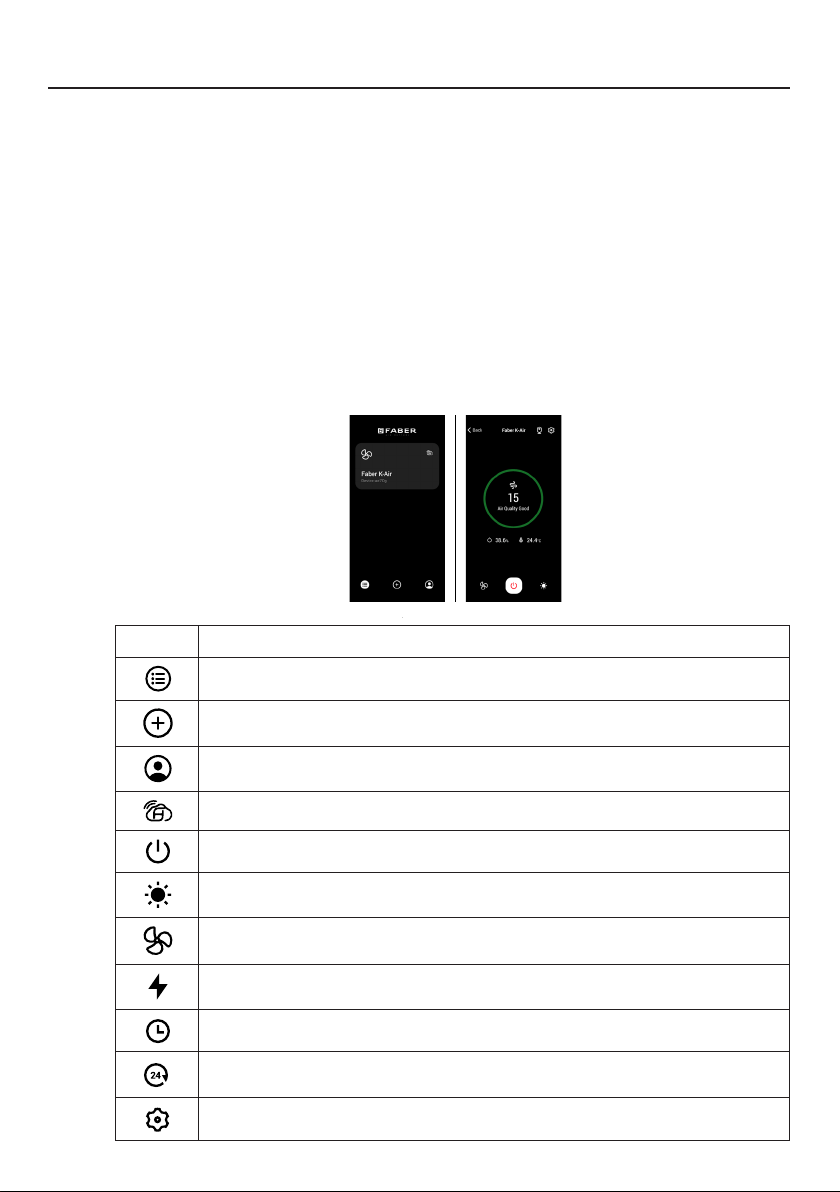
FABER CLOUD APP
Faber Cloud App
Your range hood is compatible with the Faber Cloud app. All you need is a
Internet connected Wi-Fi network that is within range of the range hood.
You can control all the functions of your range hood from anywhere using a
mobile device or your Amazon Alexa or Google Home smart speaker. When
connected to your smart speaker, you can control your hood with your voice.
The Faber Cloud app is available on iOS devices using iOS 11.0 or later or
Android devices using Android version 8 or later. Visit the Apple App Store
or Google Play Store for more information. Your range hood will have full
functionality if you are not using the Wi-fi or the Faber CLoud App features,
neither are required.
Please review the included Quick Connect Start Guide for more information.
Icon Function
5. FABER CLOUD APP
The Faber Cloud App is available for
iOS and Android smartphones and al-
lows remote access to all hood func-
tions.
Icon Function
Home page
Add new device
User profile management
Connected to Faber Wi-Fi network
Hood on/off
Lighting system management
Motor speed management
Intensive Function
24h Function
Delay Function
Automatic Function
App settings management
6. REMOTE CONTROL
• This appliance can be controlled us-
ing a remote control.
• ATTENTION: before proceeding, ac-
tivate K-Link Mode on the remote
control (see the device manual for
further details).
7. LIGHTING
• Please contact the Service Depart-
ment to change it ("Please contact
the service department to purchase
it").
8
Home page
5. FABER CLOUD APP
The Faber Cloud App is available for
iOS and Android smartphones and al-
lows remote access to all hood func-
tions.
Icon Function
Home page
Add new device
User profile management
Connected to Faber Wi-Fi network
Hood on/off
Lighting system management
Motor speed management
Intensive Function
24h Function
Delay Function
Automatic Function
App settings management
6. REMOTE CONTROL
• This appliance can be controlled us-
ing a remote control.
• ATTENTION: before proceeding, ac-
tivate K-Link Mode on the remote
control (see the device manual for
further details).
7. LIGHTING
• Please contact the Service Depart-
ment to change it ("Please contact
the service department to purchase
it").
8
Add new device
5. FABER CLOUD APP
The Faber Cloud App is available for
iOS and Android smartphones and al-
lows remote access to all hood func-
tions.
Icon Function
Home page
Add new device
User profile management
Connected to Faber Wi-Fi network
Hood on/off
Lighting system management
Motor speed management
Intensive Function
24h Function
Delay Function
Automatic Function
App settings management
6. REMOTE CONTROL
• This appliance can be controlled us-
ing a remote control.
• ATTENTION: before proceeding, ac-
tivate K-Link Mode on the remote
control (see the device manual for
further details).
7. LIGHTING
• Please contact the Service Depart-
ment to change it ("Please contact
the service department to purchase
it").
8
User profile management
5. FABER CLOUD APP
The Faber Cloud App is available for
iOS and Android smartphones and al-
lows remote access to all hood func-
tions.
Icon Function
Home page
Add new device
User profile management
Connected to Faber Wi-Fi network
Hood on/off
Lighting system management
Motor speed management
Intensive Function
24h Function
Delay Function
Automatic Function
App settings management
6. REMOTE CONTROL
• This appliance can be controlled us-
ing a remote control.
• ATTENTION: before proceeding, ac-
tivate K-Link Mode on the remote
control (see the device manual for
further details).
7. LIGHTING
• Please contact the Service Depart-
ment to change it ("Please contact
the service department to purchase
it").
8
Connected to Faber Wi-Fi network
5. FABER CLOUD APP
The Faber Cloud App is available for
iOS and Android smartphones and al-
lows remote access to all hood func-
tions.
Icon Function
Home page
Add new device
User profile management
Connected to Faber Wi-Fi network
Hood on/off
Lighting system management
Motor speed management
Intensive Function
24h Function
Delay Function
Automatic Function
App settings management
6. REMOTE CONTROL
• This appliance can be controlled us-
ing a remote control.
• ATTENTION: before proceeding, ac-
tivate K-Link Mode on the remote
control (see the device manual for
further details).
7. LIGHTING
• Please contact the Service Depart-
ment to change it ("Please contact
the service department to purchase
it").
8
Hood on/off
5. FABER CLOUD APP
The Faber Cloud App is available for
iOS and Android smartphones and al-
lows remote access to all hood func-
tions.
Icon Function
Home page
Add new device
User profile management
Connected to Faber Wi-Fi network
Hood on/off
Lighting system management
Motor speed management
Intensive Function
24h Function
Delay Function
Automatic Function
App settings management
6. REMOTE CONTROL
• This appliance can be controlled us-
ing a remote control.
• ATTENTION: before proceeding, ac-
tivate K-Link Mode on the remote
control (see the device manual for
further details).
7. LIGHTING
• Please contact the Service Depart-
ment to change it ("Please contact
the service department to purchase
it").
8
Lighting system management
5. FABER CLOUD APP
The Faber Cloud App is available for
iOS and Android smartphones and al-
lows remote access to all hood func-
tions.
Icon Function
Home page
Add new device
User profile management
Connected to Faber Wi-Fi network
Hood on/off
Lighting system management
Motor speed management
Intensive Function
24h Function
Delay Function
Automatic Function
App settings management
6. REMOTE CONTROL
• This appliance can be controlled us-
ing a remote control.
• ATTENTION: before proceeding, ac-
tivate K-Link Mode on the remote
control (see the device manual for
further details).
7. LIGHTING
• Please contact the Service Depart-
ment to change it ("Please contact
the service department to purchase
it").
8
Motor speed management
5. FABER CLOUD APP
The Faber Cloud App is available for
iOS and Android smartphones and al-
lows remote access to all hood func-
tions.
Icon Function
Home page
Add new device
User profile management
Connected to Faber Wi-Fi network
Hood on/off
Lighting system management
Motor speed management
Intensive Function
24h Function
Delay Function
Automatic Function
App settings management
6. REMOTE CONTROL
• This appliance can be controlled us-
ing a remote control.
• ATTENTION: before proceeding, ac-
tivate K-Link Mode on the remote
control (see the device manual for
further details).
7. LIGHTING
• Please contact the Service Depart-
ment to change it ("Please contact
the service department to purchase
it").
8
Intensive Function
5. FABER CLOUD APP
The Faber Cloud App is available for
iOS and Android smartphones and al-
lows remote access to all hood func-
tions.
Icon Function
Home page
Add new device
User profile management
Connected to Faber Wi-Fi network
Hood on/off
Lighting system management
Motor speed management
Intensive Function
24h Function
Delay Function
Automatic Function
App settings management
6. REMOTE CONTROL
• This appliance can be controlled us-
ing a remote control.
• ATTENTION: before proceeding, ac-
tivate K-Link Mode on the remote
control (see the device manual for
further details).
7. LIGHTING
• Please contact the Service Depart-
ment to change it ("Please contact
the service department to purchase
it").
8
Delay Function
5. FABER CLOUD APP
The Faber Cloud App is available for
iOS and Android smartphones and al-
lows remote access to all hood func-
tions.
Icon Function
Home page
Add new device
User profile management
Connected to Faber Wi-Fi network
Hood on/off
Lighting system management
Motor speed management
Intensive Function
24h Function
Delay Function
Automatic Function
App settings management
6. REMOTE CONTROL
• This appliance can be controlled us-
ing a remote control.
• ATTENTION: before proceeding, ac-
tivate K-Link Mode on the remote
control (see the device manual for
further details).
7. LIGHTING
• Please contact the Service Depart-
ment to change it ("Please contact
the service department to purchase
it").
8
24H function
5. FABER CLOUD APP
The Faber Cloud App is available for
iOS and Android smartphones and al-
lows remote access to all hood func-
tions.
Icon Function
Home page
Add new device
User profile management
Connected to Faber Wi-Fi network
Hood on/off
Lighting system management
Motor speed management
Intensive Function
24h Function
Delay Function
Automatic Function
App settings management
6. REMOTE CONTROL
• This appliance can be controlled us-
ing a remote control.
• ATTENTION: before proceeding, ac-
tivate K-Link Mode on the remote
control (see the device manual for
further details).
7. LIGHTING
• Please contact the Service Depart-
ment to change it ("Please contact
the service department to purchase
it").
8
App settings management
5. FABER CLOUD APP
The Faber Cloud App is available for
iOS and Android smartphones and al-
lows remote access to all hood func-
tions.
Icon Function
Home page
Add new device
User profile management
Connected to Faber Wi-Fi network
Hood on/off
Lighting system management
Motor speed management
Intensive Function
24h Function
Delay Function
Automatic Function
App settings management
6. REMOTE CONTROL
• This appliance can be controlled us-
ing a remote control.
• ATTENTION: before proceeding, ac-
tivate K-Link Mode on the remote
control (see the device manual for
further details).
7. LIGHTING
• Please contact the Service Depart-
ment to change it ("Please contact
the service department to purchase
it").
8

28
The remote control replicates the functions of the
control panel the hood. #REMORIG
ATTENTION: some functions can onlybe activated
via the remote control(refer to the device manual
for furtherdetails).
REMOTE CONTROL (Optional)
Cleaning Exterior surfaces:
Please note, abrasives and scouring agents can scratch range hood
finishes and should not be used to clean finished surfaces.
Stainless Steel finish cleaning instructions:
Clean exterior surfaces with a commercially available stainless steel
cleaner.
CLEANING STAINLESS STEEL
29
CARING FOR FILTERS
Open the Panel by pulling it down.
Remove the lter, pushing the lever
towards the back of the unit while
pulling downward.
Wash the lter without bending it.
Leave it to dry thoroughly before
replacing. If the surface of the lter
changes color over time, efciency
will not be affected.
To replace the lter, push the lter up
into position while holding the lever
back, then release lever to lock in
place.
1
2
3
ace
CLEANING METAL GREASE FILTERS
The metal grease lters can be cleaned in hot detergent solution or washed
in the dishwasher.
They should be cleaned every 2 months use, or more frequently if use is
particularly heavy.
NOTES:
• Cleaning in a dishwasher may dull the nish of the metal grease lters.
• Ensure that the lters are completely dry before installing them back into
the Range Hood.
CLEANING EXTERIOR SURFACES
Please note, abrasives and scouring agents can scratch range hood nishes
and should not be used to clean nished surfaces.
Stainless Steel nish cleaning instructions:
Clean exterior surfaces with a commercially available stainless steel cleaner.
30
Open the Panel by pulling
it down. Remove the lter,
pushing the lever towards
the back of the unit while
pulling downward.
Remove the saturated
charcoal filter by rotating
it clockwise ( backwards)
until it unlocks from the
motor housing and pull off
sideways.
To re-insert each charcoal
filter, place up against the
side of the blower and push
it inward. Then turn the
charcoal filter clockwise
(forward) until it fits into
place.
1
2
3
REPLACING ACTIVATED CHARCOAL FILTER
The Activated Charcoal Filters are not washable and cannot be regenerated,
and must be replaced approximately every 4 months of operation, or more
frequently with heavy usage.
REPLACING LIGHTING
LED lights must be replaced by Faber factory authorized service.
ace
W
W
31
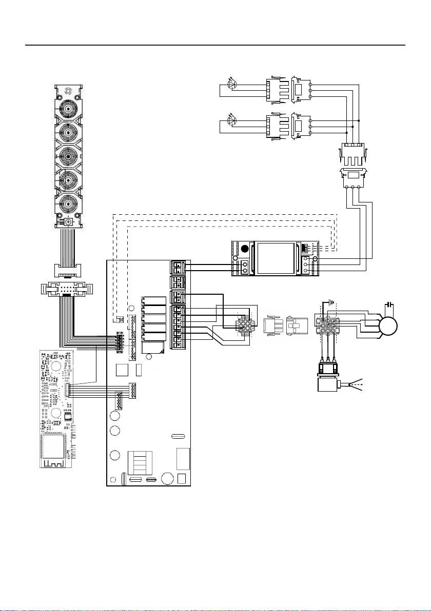
WIRING DIAGRAM
0123456789
H90_1008
01
Drawing N : Rev :
Modif. by
These drawings and specifications are the property of Franke Technology and
Trademartk Ltd and shall not be reproduced.copied or trasferred to any third party
without the prior written permission of Franke Tecnology and Trandemark Ltd.
Switzerland.It is strictly prohibited to get quotes from the drawing or bring
modifications without the prior written conset of franke Techology and Trademark
Doc.status
Modification description
Approved date
WIRING DIAGR.M8-4V ATF WI-FI 10W CL.I
Approved by
Denomination
Doc Type
Creation date
30/05/2022
FABER Corrado
Created by
991.0682.386
Code
220-240V 50-60HZ
PIN 1
PIN 3
PIN 9
PIN 7
USER INTERFACE
PIN 1
PIN 3
PIN 9
PIN 7
BRW
PNK
L-B
BLU
WHT
GRY
BLK
SEC.
ELECTRONIC
TRNSFORMER
L N
GRY
WHT
BLK
RED
M8-4V
BRW
ORG
BLK
GRY
WHT
BLU
BRW
L-B
Y-G
.
BLK
.
RED
+
GRY
RED
BLK
GRY
3
2
1
3
2
1
(-)
3
3
WHT
(-)
2
2
BLK
?led1
(+)
1
1
GRY
(-)
3
3
WHT
(-)
2
2
BLK
(+)
1
1
GRY
ORG
ORG

32
WARRANTY
Franke Home Solutions Warranty for Franke and Faber Branded Product Effective March 1, 2022
In the United States, Canada and Latin America, Franke warrants the Faber branded products from manufacturing defects
in material and workmanship when purchased from a Franke or Faber Authorized Retailer pursuant to product-specific
warranties detailed herein (each, a “Warranty” and collectively, the “Warranties”). The products must be properly installed, per
Franke’s installation instructions, in their original installation, and used in normal indoor residential kitchen applications. Any
products or components which have been modified or altered from their original intended condition will void the Warranty.
The Franke Warranties for Faber branded products are limited to the original purchaser and are non- transferrable. These
Warranties do not include products purchased from non-Authorized Retailers, products that are obsolete or discontinued, or
products that were previous display models. All issues with installed products are considered warranty claims and not subject
to the Return Policy. Franke reserves the right to inspect any Franke / Faber product reported to be defective pursuant to a
Warranty claim and the original installation prior to providing a replacement product and/or component. All decisions are final.
In no situation shall the liability of Franke exceed the amount of the original purchase price.
The Warranties do not cover, and Franke shall not be liable for, any damage to products or components resulting from misuse
or abuse, accidental damages, normal wear such as scuffs, scratches or finish reduction/fading, improper installation, abnormal
usage, negligence, damage caused by improper maintenance or cleaning. Damage caused by impurities, corrosive chemicals
or acts beyond Franke’s control are not covered by any Warranty. Service calls to correct the installation of a range hood,
instructions on how to operate a range hood, to replace or repair house fuses or to correct house wiring or plumbing are not
covered by any Warranty. Service calls to repair or replace range hood light bulbs, fuses or filters and these consumable part
costs are also excluded from Warranty coverage. Installation not in accordance with electrical or plumbing codes or Franke
/ Faber documentation are not covered by any Warranty. Replacement parts or repair labor costs for units operated outside
the United States, Canada or Latin America, including any non-UL or C-UL or non-NOM approved Franke / Faber range hoods
are excluded from Warranty coverage. Expenses for travel and transportation for service in remote locations and pickup and
delivery charges are not covered by any Warranty. Franke / Faber range hoods should always be serviced in the home in their
original installation.
Franke / Faber product replacements do not include liability for project delays. Product replacements are not guaranteed to
be exact replacements. If the original product is not available at the time of the warranty claim, at Franke’s option, the product
replacements will be of similar size, material, and value. Any products or components which have been modified or altered,
from its original intended condition will void the warranty.
The Warranties do not allow recovery of incidental or consequential damages such as loss of use, delay, property damage or
other consequential damage, and Franke accepts no liability for such damages. Each Warranty is limited to the conditions set
forth herein and to the applicable warranty period specified herein and is exclusive. EXCEPT FOR THE WARRANTIES SET
FORTH HEREIN, FRANKE MAKES NO WARRANTY WHATSOEVER WITH RESPECT TO THE PRODUCTS, INCLUDING, BUT
NOT LIMITED TO, (1) ANY WARRANTY OF MERCHANTABILITY, (2) WARRANTY OF FITNESS FOR A PARTICULAR PURPOSE,
(3) WARRANTY OF TITLE, OR (4) WARRANTY AGAINST INFRINGEMENT OF INTELLECTUAL PROPERTY RIGHTS OF A
THIRD PARTY, WHETHER EXPRESS OR IMPLIED BY LAW, COURSE OF DEALING, COURSE OF PERFORMANCE, USAGE OF
TRADE OR OTHERWISE. LEGAL DISCLAIMER PLEASE
READ CAREFULLY. Franke Kitchen Systems LLC provides the above information to you as a public service to our customers.
By accessing and using this information, you agree to the following and to comply with all applicable laws. If you do not agree
with these terms and conditions, do not use this information. While we try to keep the information current, changes may have
occurred since its creation. Contact your Regional Manager or Customer Service to verify information regarding Franke Kitchen
Systems LLC programs and their use by you.
Franke / Faber Range Hood Limited Warranty:
Franke / Faber range hoods are warranted against any defect in materials or workmanship for the original purchaser for a
period of two (2) years from the date of original purchase when used in standard residential indoor applications. This warranty
covers labor and replacement parts. Franke, at its option, may repair or replace the product or components necessary to
restore the product to good working condition.

33
This warranty supersedes all other warranties, expressed or implied. No employee, field sales
representatives, or distribution persons are authorized to give any warranties on behalf of Franke Kitchen
Systems, LLC
To make an installed product warranty claim please contact Franke at the provided contact information
below. All warranty claims must include the following for processing:
1. Proof of purchase from Franke or Faber Authorized Retailer
2. Original purchaser’s name, address (included city, state, zip), email address and phone number
3. Franke / Faber model and serial number
4. Date of installation
5. Description of the defect
6. Photos of the defect
In North America and Latin America:
Franke Home Solutions
Attn: Warranty Department
800 Aviation Parkway
Smyrna, TN 37167
HS-Warranty.US@Franke.com
Legal Entity:
Franke Kitchen Systems LLC

34
CONTENU
Section Page
Consignes de sécurité importantes 35
Dimensions de la hotte 38
Exigences en matière de hauteur d'installation 39
Pièces 40
Outils nécessaires 42
Options de la méthode d'évacuation par conduits 43
Montage de la hotte d’aspiration
44
Choisissez Votre Méthode De Conduits
48
Branchement électrique
51
Utilisation des commandes
53
Application Faber Cloud
59
Télécommande
60
Nettoyage de l'acier inoxydable
60
Entretien des ltres
61
Remplacement de l'éclairage
62
Schéma de câblage
63
Garantie
64

35
CONSIGNES DE SÉCURITÉ IMPORTANTES
LISEZ ET SAUVEGARDEZ CES CONSIGNES AVANT DE
COMMENCER L’INSTALLATION DE CETTE HOTTE DE CUISINIÈRE
AVERTISSEMENT: - POUR RÉDUIRE LE RISQUE D'UN FEU DE GRAISSE SUR LA CUISINIÈRE:
a) Ne laissez jamais les unités de surface sans surveillance à des valeurs de réglage élevés. Les déb-
ordements provoquent des fumées et peuvent s'enammer s’ils sont graisseux. Faites chauffer les
huiles lentement à feu doux ou moyen.
b) Mettez toujours la hotte EN MARCHE lorsque vous cuisinez à feu vif ou lorsque vous ambez des
mets (par exemple, des crêpes Suzette, des cerises Jubilée, du bœuf au poivre ambé).
c) Nettoyez fréquemment les ventilateurs. La graisse ne doit pas s'accumuler sur le ventilateur ou le
ltre.
d) Utilisez une casserole de taille appropriée. Utilisez toujours des ustensiles de cuisson adaptés à la
taille de l'élément de surface.
AVERTISSEMENT: - POUR RÉDUIRE LES RISQUES DE BLESSURES EN CAS DE FEU DE GRAISSE SUR
LE DESSUS DE LA CUISINIÈRE, RESPECTEZ LES CONSIGNES SUIVANTES*:
a) ÉTOUFFEZ LES FLAMMES avec un couvercle hermétique, une plaque à biscuits ou un plateau métall-
ique, puis éteignez le brûleur. VEILLEZ A ÉVITER LES BRÛLURES. Si les ammes ne s'éteignent pas
immédiatement, ÉVACUEZ ET APPELEZ LES POMPIERS.
b) Ne RAMASSEZ JAMAIS UNE CASSEROLE ENFLAMMÉE - Vous pourriez vous brûler.
c) N'UTILISEZ PAS D'EAU, y compris des torchons ou des serviettes humides - une violente explosion
de vapeur en résulterait.
d) Utilisez un extincteur UNIQUEMENT si:
1. Vous savez que vous avez un extincteur de classe ABC et vous savez déjà comment l'utiliser.
2. Le feu est petit et limité dans la zone où il s’est déclenché.
3. Les pompiers ont été appelés.
4. Vous pouvez combattre le feu en tournant le dos à une sortie.
* Basé sur les «Conseils de sécurité pour la cuisine» publié par laNFPA
AVERTISSEMENT - POUR RÉDUIRE LE RISQUE D'INCENDIE OU DE CHOC ÉLECTRIQUE, n'utilisez pas
ce ventilateur avec un dispositif de contrôle de vitesse à semi-conducteurs.
AVERTISSEMENT - POUR RÉDUIRE LES RISQUES D'INCENDIE, DE CHOC ÉLECTRIQUE OU DE BLESSURE,
RESPECTEZ LES CONSIGNES SUIVANTES:
1. N'utilisez cet appareil que conformément aux instructions du fabricant. Si vous avez des questions,
contactez le fabricant.
2. Avant de procéder à l'entretien ou au nettoyage de l'appareil, coupez l'alimentation électrique au
niveau du panneau de service et verrouillez le dispositif de déconnexion de service pour éviter
toute remise sous tension accidentelle. Lorsque vous ne pouvez pas verrouiller le dispositif de
déconnexion du service, xez solidement un dispositif d'avertissement bien visible, tel qu'une
étiquette, sur le panneau de service.
ATTENTION: Pour une utilisation générale de ventilation seulement. Ne l’utilisez pas pour évacuer des
matières et des vapeurs dangereuses ou explosives.
AVERTISSEMENT - POUR RÉDUIRE LES RISQUES D'INCENDIE, DE CHOC ÉLECTRIQUE OU DE BLESSURE,
RESPECTEZ LES CONSIGNES SUIVANTES:
1. Conez les travaux d'installation et le câblage électrique à une ou plusieurs personnes qualiées,
conformément à tous les codes et normes en vigueur, y compris les constructions résistantes au feu.
2. Une quantité sufsante d'air est nécessaire pour une bonne combustion et l'évacuation des gaz
par le conduit (cheminée) de l'équipement de combustion an d'éviter le refoulement. Suivez les
directives du fabricant de l'équipement de chauffage et les normes de sécurité telles que celles
publiées par la National Fire Protection Association (NFPA) et l'American Society for Heating, Refri-
geration and Air Conditioning Engineers (ASHRAE), ainsi que les autorités locales chargées du code.
36
TOUTES LES OUVERTURES DANS LES PAROIS ET LE PLANCHER OÙ LA HOTTE
EST INSTALLÉE DOIVENT ÊTRE SCELLÉES.
Cette hotte nécessite un dégagement d'au moins 24" entre le bas de la hotte et la surface de cuisson ou
le comptoir. Elle a été approuvée par les LA à cette distance de la table de cuisson.
Ce dégagement minimum peut être plus élevé selon les codes du bâtiment locaux. Pour les tables de cuisson
au gaz et les cuisinières combinées, un minimum de 30" est recommandé et peut être exigé.
Les armoires suspendues des deux côtés de l’appareil doivent se trouver à au moins 18" au-dessus de la
surface de cuisson ou du comptoir. Consultez les instructions d'installation de la table de cuisson ou de la
cuisinière données par le fabricant avant de faire des découpes.
INSTALLATION DANS DES MOBIL-HOMES L'installation de cette hotte de cuisine doit être conforme
aux normes de construction et de sécurité des maisons mobiles, titre 24 CFR, partie 3280 (anciennement
norme fédérale pour la construction et la sécurité des mobil-homes, titre 24, HUD, partie 280). Voir la
section Exigences électriques"
• Le système de ventilation DOIT se terminer à l'extérieur de la maison.
• NE PAS faire aboutir le conduit dans un grenier ou un autre espace fermé.
• NE PAS utiliser de capuchons muraux de 4" de type blanchisserie.
• Les conduits de type exible ne sont pas recommandés.
• NE PAS obstruer le ux d'air de combustion et de ventilation.
• Le non-respect des exigences en matière de ventilation peut entraîner un incendie.
AVERTISSEMENT
!
EXIGENCES EN MATIÈRE DE VENTILATION
Déterminez la méthode de ventilation qui convient le mieux à votre application. Les conduits peuvent
passer soit par le mur, soit par le toit.
La longueur des conduits et le nombre de coudes doivent être réduits au minimum pour assurer une perfor-
mance efcace. La taille des conduits doit être uniforme. N'installez pas deux coudes ensemble. Utilisez
du ruban adhésif pour sceller tous les joints du système de conduits. Utilisez du calfeutrage pour sceller
l'ouverture du mur extérieur ou du plancher autour du capuchon.
Les conduits exibles ne sont pas recommandés. Ils créent une contre-pression et des turbulences d'air
qui réduisent considérablement les performances.
Assurez-vous qu'il y a un dégagement approprié dans le mur ou le plancher pour le conduit d'évacuation
avant de faire des découpes. Ne coupez pas une solive ou un montant à moins que cela ne soit absolu-
ment nécessaire. Si vous devez couper une solive ou un montant, veuillez construire un cadre de support.
AVERTISSEMENT - Pour réduire les risques d'incendie, utilisez uniquement des conduits métalliques.
ATTENTION - Pour réduire les risques d'incendie et pour évacuer correctement l'air, assurez-vous de
canaliser l'air vers l'extérieur - Ne faites pas passer l'air évacué dans des espaces à l'intérieur des murs
ou des plafonds ou dans des greniers, des vides sanitaires ou des garages.
Installations par temps froid
Veuillez installer un clapet anti-retour supplémentaire pour minimiser le retour de l'air froid ainsi qu’un
dispositif de coupure thermique non métallique pour minimiser la conduction des températures extérieures
dans le système de ventilation. Le clapet doit se trouver du côté de l'air froid de la coupure thermique.
La coupure doit être aussi près que possible de l'endroit où le système de ventilation entre dans la partie
chauffée de la maison.
3. Lorsque vous coupez ou percez un mur ou un plafond, n'endommagez pas le câblage électrique
et les raccordements aux services utilitaires cachés.
4. Les ventilateurs à conduit doivent toujours être évacués vers l'extérieur.
37
EXIGENCES ÉLECTRIQUES
Une alimentation électrique de 120volts, 60Hz, uniquement en CA, est requise sur un
circuit séparé à fusible de 15ampères. Nous recommandons un fusible à retardement
ou un disjoncteur. Le fusible doit être dimensionné en fonction des codes locaux et de
la puissance électrique de l'appareil, comme indiqué sur la plaque signalétique située
à l'intérieur de l'appareil, près du compartiment de câblage.
• Une mise à la terre électrique est requise sur cette hotte.
• Si le tube d'eau froide est interrompu par du plastique, des joints non métalliques ou
d'autres matériaux, NE l'utilisez PAS pour la mise à la terre.
• NE mettez PAS à la terre un tube de gaz.
• N’ayez PAS de fusible dans le circuit neutre ou de mise à la terre. Un fusible dans le
circuit neutre ou de mise à la terre pourrait provoquer un choc électrique.
• Vériez auprès d'un électricien qualié si vous avez des doutes quant à la mise à la
terre de la hotte.
• Le non-respect des exigences électriques peut entraîner un incendie.
AVERTISSEMENT
!
38
DIMENSIONS DE LA HOTTE
39
MIN. 24" AU-DESSUS DE L'ÉLECTRICITÉ/MIN. 30" SUR GAZ
EXIGENCES EN MATIÈRE DE HAUTEUR
D'INSTALLATION
Min. 24" Min. 30"

40
PIÈCES
RÉF. PIÈCE
A
Corps de hotte, y compris les commandes, l’éclairage, le moteur, les filtres
1
B
Cordon d’alimentation
1
C
Volet du clapet
2
D
Anneau de clapet
1
E
Couvercle de grille de recirculation
1
F
Couvercle
2
RÉF. PIÈCE
G
Vis 1/8" x 3/8"
4
PIÈCES INCLUSES

41
A
B
C
A
B
H1
D
P
E
F
G
G

42
PIÈCES NÉCESSAIRES
PIÈCES (suite)
PIÈCE
Conduit métallique rond de 6"
Le capuchon mural/le capuchon de toit doit être acheté séparé-
ment.
OUTILS NÉCESSAIRES
OUTIL
Mètre ruban
Crayon
Perceuse électrique avec mèche de 5/16"
Tournevis Phillips
Gants de travail
ACCESSOIRES DISPONIBLES
ACCESSOIRES SKU#
KIT DE FILTRE À CHARBON FILTER1
KIT DE FILTRE À CHARBON LAVABLE LONGUE DURÉE FILTER1LL2
BOÎTIER DE CÂBLAGE FIXE WIREBOX
TÉLÉCOMMANDE REMORIG

43
OPTIONS DE LA MÉTHODE D’ÉVACUATION PAR
CONDUITS
Conduit avec sortie ronde de 6":
– Vertical
– Horizontal
OPTION DE RECIRCULATION SANS CONDUIT
Nécessite l'achat de
l'accessoire charbon
actif.
Horizontale
Verticale
6"
44
Découpez l’ouverture dans le dessous de l’armoire comme indiqué sur la
figure ci-dessous.
1
MONTAGE DE LA HOTTE D’ASPIRATION
X
Y
Min.13/16
"
Min. 3/4
"
Modèle X Y
28" 26 9/16" 10 7/16"
Profondeur
Épaisseur

45
Installez la hotte d’insertion dans l’ouverture de l’armoire et engagez com-
plètement les clips de montage latéraux à ressort sur la base en bois de
l’armoire.
Ensuite, à partir du dessous de l’insert, comme illustré sur la figureA, locali-
sez la vis dans chacun des clips de montage latéral.
Pour verrouiller la hotte d’insertion en position, serrez la vis de chacun des
deux clips de montage latéral.
2
A
2x
Deux personnes peuvent
être nécessaires pour
l’installation.
46
Insérez le couvercle
F
dans chacune des deux ouvertures de vis comme
indiqué.
3
B
2x
F

47
Si la hotte n’est pas nivelée dans la partie centrale, fixez les deux vis
G
comme indiqué ci-dessous.
4
A
B
G
48
Cassez les 4pièces prédécoupées et installez l’anneau
D
inclus avec la
hotte avant de la raccorder aux conduits.
2
Installation de ventilation avec conduit
1
Installez les 2volets de de clapet
C
inclus avec la hotte de cuisinière
comme illustré.
CHOISISSEZ VOTRE MÉTHODE DE CONDUITS
D
C

49
Installez le capuchon de toit ou de mur acheté séparément.
Raccordez le conduit métallique de 6"pouces au capuchon de toit ou de
mur, puis fixez le conduit.
3
50
Option de recirculation sans conduit
1
Pour l'évent de recirculation sans conduit, acheminez le conduit à un endroit
au-dessus de la hotte où l'évacuation est renvoyée dans la pièce.
Utilisez la grille d'évent de recirculation incluse
E
pour couvrir l'ouverture.
Fixez la grille à l'aide des 2vis
G
fournies dans le kit d'installation.
Kit de filtre à charbon requis
sku #FILTER1
Kit de filtre à charbon durable
sku #FILTER1LL2
(acheté séparément)
´
E
G
51
BRANCHEMENT ÉLECTRIQUE
INSTALLATION ÉLECTRIQUE AVEC CÂBLE DE CONNEXION
INSTRUCTIONS DE MISE A LA TERRE. Cet appareil doit être mis à la terre. En cas
de court-circuit électrique, la mise à la terre réduit le risque de choc électrique en
fournissant un fil d'échappement pour le courant électrique. Cet appareil est équipé
d'un cordon comportant un fil de mise à la terre avec prise de terre. La fiche doit
être branchée dans une prise de courant correctement installée avec mise à la terre.
AVERTISSEMENT: une mise à la terre incorrecte peut entraîner un risque de choc
électrique.
Consultez un électricien qualifié si vous ne comprenez pas parfaitement les in-
structions de mise à la terre ou si vous avez des doutes quant à la mise à la terre de
l'appareil.
N'utilisez pas de rallonge électrique. Si le cordon d'alimentation est trop court, de-
mandez à un électricien qualifié d'installer une prise à proximité de l'appareil.
1
AVERTISSEMENT: «Le cordon d’alimentation doit être accessible pour ins-
pection après l’installation.»
Max. 33 7/16”
Accessoire de boîtier
de câblage à connexion
directe sku # WIREBOX
(acheté séparément)
INSTALLATION ÉLECTRIQUE AVEC BOÎTIER DE CÂBLAGE EN OPTION
Pour une installation de câblage permanente, utilisez uniquement avec le kit de
boîtier de câblage de hotte de cuisinière répertorié
sku # WIREBOX, fabriqué par Faber

52
Ouvrez le panneau en le tirant vers le bas. Retirez le ltre à graisse en pous-
sant le levier vers l’arrière de l’appareil tout en tirant vers le bas.
Fixez chaque filtre à charbon à la grille noire de chaque côté du ventilateur.
Appuyez fermement le filtre à charbon sur la grille noire du côté du
ventilateur et tournez le filtre dans le sens horaire (vers l’avant de la hotte
d’insertion) jusqu’à ce qu’il se verrouille en place. Tournez dans le sens
antihoraire (vers l’arrière de la hotte d’insertion) pour le retirer.
Accessoire nécessaire pour le filtre
à charbon actif - sku sku #FILTER1
ou #FILTER1LL2
POUR L’OPTION DE RECIRCULATION SANS CONDUIT
1
2
ace
W
W
53
UTILISATION DES COMMANDES
POUR DE MEILLEURS RÉSULTATS
Mettez la hotte en marche plusieurs minutes avant la cuisson pour assu-
rer une bonne circulation de l'air. Laissez la hotte fonctionner pendant
plusieurs minutes après la fin de la cuisson pour évacuer la fumée et les
odeurs de la cuisine.
A - LUMIÈRES
B - ALIMENTATION
C - VITESSE2
D - VITESSE3
E - INTENSIF
F - LED
A - LUMIÈRES: les lumières ont 3niveaux (haut,
moyen, éteint), appuyez sur le bouton d’éclairage
pour changer les niveaux. Il est possible de changer
l’intensité de la lumière de manière cyclique. À l’aide
de longues pressions séparées, il est possible de faire
varier le ton de la lumière entre «chaud» et «froid».
BOUTON FONCTION
INDICATEUR
B - ALIMENTATION: une pression rapide allume/
éteint le moteur à la vitesse un.
C - VITESSE2: une pression rapide allume le
moteur à la vitesse deux.
Toutes lesLED clignotent
deux fois (alarme activée).
Toutes lesLED allumées
pendant 1seconde (alarme
désactivée).
D - VITESSE3: une pression rapide allume le moteur
à la vitesse trois.
Réinitialiser l’alarme du filtre à graisse et/ou du
filtre à charbon: une pression longue avec le moteur
et les lumières éteints pour réinitialiser les alarmes de
lavage du filtre.
Toutes lesLED cli-
gnotent 3fois.
Activer/Désactiver l’alarme du filtre à
charbon: une pression longue avec les
lumières allumées et le moteur éteint activera
ou désactivera l’alarme du filtre à charbon.

54
E - NIVEAU INTENSIF1: une pression
rapide activera le niveau de vitesse intensif1
pendant 6minutes.
BOUTON FONCTION
INDICATEUR
Alarme de filtre à graisse: si les boutons de
vitesse deux et intensive sont allumés, cela
signifie que l’alarme de saturation du filtre à
graisse est activée et que les filtres à graisse
doivent être lavés. L’alarme se déclenche
après 100heures de fonctionnement.
Alarme de filtre à charbon: si l’alarme
est activée, les voyants de vitesse deux et
intensive clignoteront. Cela signifie que les
filtres à charbon doivent être remplacés ET
que les filtres à graisse doivent être lavés.
L’alarme du filtre à charbon se déclenche
après 200heures de fonctionnement.

55
INFORMATIONS WI-FI
Cet appareil est conforme à la partie15 des règles de laFCC. Le fonctionnement
est soumis aux deux conditions suivantes: (1) Cet appareil ne doit pas causer
d’interférences nuisibles et (2) cet appareil doit accepter toute interférence reçue, y
compris les interférences susceptibles de provoquer un fonctionnement indésirable.
Remarque: Cet équipement a été testé et déclaré conforme aux limites d’un
appareil numérique de classeB, conformément à la partie15 des règles de laFCC.
Ces limites sont conçues pour fournir une protection raisonnable contre les
interférences nuisibles dans une installation résidentielle. Cet équipement génère,
utilise et peut émettre de l’énergie de radiofréquence et, s’il n’est pas installé et
utilisé conformément aux instructions, peut causer des interférences nuisibles aux
communications radio. Cependant, il n’y a aucune garantie que des interférences ne
se produiront pas dans une installation particulière.
Si cet équipement cause des interférences nuisibles à la réception radio ou
télévision, ce qui peut être déterminé en éteignant et en rallumant l’équipement,
l’utilisateur est invité à essayer de corriger l’interférence en prenant une ou plusieurs
des mesures suivantes:
• Réorientez ou repositionnez l’antenne de réception.
• Augmentez la distance entre l’équipement et le récepteur.
• Connectez l’équipement à une prise sur un circuit autre que celui auquel le
récepteur est connecté.
• Consultez votre revendeur ou un technicien radio/TV expérimenté pour obtenir
de l’aide.
Les modifications apportées à ce produit non autorisées par Faber peuvent
invalider la compatibilité électromagnétique(CEM) et la conformité sans fil et
refuser l’autorisation d’utiliser le produit.
Ce produit a démontré la conformitéCEM dans des conditions qui incluaient
l’utilisation de périphériques conformes et de câbles blindés entre les composants
du système. Il est important d’utiliser des périphériques conformes et des câbles
blindés entre les composants du système pour réduire la possibilité de causer des
interférences aux radios, téléviseurs et autres appareils électroniques.
Exposition à l’énergie de radiofréquence. La puissance de sortie rayonnée de cet
appareil respecte les limites d’exposition aux fréquences radioFCC etIC. Cet
appareil doit être utilisé avec une distance de séparation minimale de 20cm (8po)
entre l’équipement et le corps d’une personne.
Informations sur l’appareil connecté
Contient l’ID FCC: 2AC7Z-ESPWROOM32D
Contient IC: 21098-ESPWROOM32D
Modèle: ESP32-WROOM-32D
CAN ICES-003(B)/NMB-003(B)
56
BOUTON FONCTION
INDICATEUR
Activer/Désactiver la fonction de connexion
Wi-Fi.
Appuyez longuement sur le bouton de vitesse2
avec le moteur et les lumières éteints pour
activer/désactiver le Wi-Fi.
Remarque: la fonction Wi-Fi est
automatiquement activée lorsque l’utilisateur
demande la procédure de configuration Wi-Fi.
Connexion au
routeur sans fil
domestique en
cours.
Connexion Wi-Fi
activée.
Démarrage de la configuration Wi-Fi
Appuyez longuement dessus avec le moteur et
les lumières éteints pour accéder ou terminer
la procédure de configuration Wi-Fi. Avant de
commencer la procédure, utilisez l’application
Faber Cloud pour vous inscrire au système
IOTFaber. Suivez ensuite les instructions pour
ajouter un nouvel appareil et enregistrer votre
routeur sans fil domestique.
Si la procédure n’est pas terminée avec
succès en quelques minutes, arrêtez le
processus de configuration en maintenant le
bouton de niveau intensif enfoncé pendant
3secondes. Maintenez à nouveau ce bouton
enfoncé pendant 3secondes pour démarrer
le processus. La hotte arrêtera le processus de
configuration Wi-Fi s’il n’est pas terminé avec
succès dans les 15minutes.
La configuration
est en cours.
F - LED
Lorsque la
configuration est
terminé, lesLED
restent allumées
pendant
2secondes.
CONNEXIONS WI-FI

57
RÉGLAGECFM < 295CFM
Pour démarrer le processus, assurez-vous que les lumières de la hotte sont
allumées et que le moteur est éteint.
1) Appuyez surT1 et maintenez-le enfoncé pendant 7secondes jusqu’à ce
que toutes lesLED clignotent.
2) Une fois le clignotement arrêté, appuyez sur T1.
3) Le boutonT1 clignotera une fois, puis appuyez à nouveau sur le bouton
T1 pour confirmer votre choix (dans les 10secondes).
4) Les quatreLED clignoteront à nouveau pour confirmer que vous avez
terminé le réglageCFM à moins de 295CFM.
5) Appliquez l’étiquette inférieure à 295CFM à l’intérieur de la hotte
(derrière les filtres à graisse) près de l’étiquette signalétique pour
inspection et sur le devant de votre manuel d’installation/de l’utilisateur.
6) Pour confirmer votre réglage pour inspection, les boutonsT1 et T2
feront toujours fonctionner la hotte à la même vitesse. La vitesse la plus
élevée (T3) et la vitesse intensive (T4) ne fonctionneront également
plus.
Remarque: Les boutonsT2 et T3 fonctionneront désormais au même
niveau et la vitesse intensive sera désactivée.
Attention: Lorsque le réglage inférieur à 295CFM est terminé, il n’est plus
possible de modifier ce paramètre au niveauCFM d’origine.
ATTENTION: Pour un bon fonctionnement de l’application FABER CLOUD,
lorsque cette procédure est terminée, débranchez la fiche de l’alimentation
électrique et rebranchez-la.
58
RÉGLAGECFM < 395CFM
Pour démarrer le processus, assurez-vous que les lumières de la hotte sont
allumées et que le moteur est éteint.
1) Appuyez surT1 et maintenez-le enfoncé pendant 7secondes jusqu’à ce
que toutes lesLED clignotent.
2) Une fois le clignotement arrêté, appuyez sur T2.
3) Le boutonT2 clignotera une fois, puis appuyez à nouveau sur le bouton
T2 pour confirmer votre choix (dans les 10secondes).
4) Les quatreLED clignoteront à nouveau pour confirmer que vous avez
terminé le réglageCFM à moins de 395CFM.
5) Appliquez l’étiquette inférieure à 395CFM à l’intérieur de la hotte
(derrière les filtres à graisse) près de l’étiquette signalétique pour
inspection et sur le devant de votre manuel d’installation/de l’utilisateur.
6) Pour confirmer votre réglage pour inspection, la fonction de vitesse
intensive ne fonctionnera plus.
Remarque: Les boutonsT3 et T4 fonctionneront désormais au même
niveau et la vitesse intensive sera désactivée.
Attention: Lorsque le réglage inférieur à 395CFM est terminé, il n’est plus
possible de modifier ce paramètre au niveauCFM d’origine.
ATTENTION: Pour un bon fonctionnement de l’application FABER CLOUD,
lorsque cette procédure est terminée, débranchez la fiche de l’alimentation
électrique et rebranchez-la.

59
APPLICATION FABER CLOUD
Application Faber Cloud
Votre hotte est compatible avec l’application Faber Cloud. Tout ce dont vous avez be-
soin est un réseau Wi-Fi connecté à Internet qui se trouve à portée de la hotte. Vous
pouvez contrôler toutes les fonctions de votre hotte de n’importe où à l’aide d’un
appareil mobile ou de votre haut-parleur intelligent Amazon Alexa ou Google Home.
Une fois connecté à votre haut-parleur intelligent, vous pouvez contrôler votre hotte
avec votre voix.
L’application Faber Cloud est disponible sur les appareils iOS utilisant iOS11.0 ou
version ultérieure ou sur les appareils Android utilisant Android version8 ou version
ultérieure. Visitez l’Apple App Store ou le Google Play Store pour plus d’informations.
Votre hotte de cuisine disposera de toutes les fonctionnalités si vous n’utilisez pas les
fonctionnalités Wi-Fi ou l’application Faber Cloud, ni l’une ni l’autre n’est requise.
Veuillez consulter le guide de démarrage Quick Connect inclus pour plus d’informa-
tions.
Icône Fonction
5. FABER CLOUD APP
The Faber Cloud App is available for
iOS and Android smartphones and al-
lows remote access to all hood func-
tions.
Icon Function
Home page
Add new device
User profile management
Connected to Faber Wi-Fi network
Hood on/off
Lighting system management
Motor speed management
Intensive Function
24h Function
Delay Function
Automatic Function
App settings management
6. REMOTE CONTROL
• This appliance can be controlled us-
ing a remote control.
• ATTENTION: before proceeding, ac-
tivate K-Link Mode on the remote
control (see the device manual for
further details).
7. LIGHTING
• Please contact the Service Depart-
ment to change it ("Please contact
the service department to purchase
it").
8
Page d’accueil
5. FABER CLOUD APP
The Faber Cloud App is available for
iOS and Android smartphones and al-
lows remote access to all hood func-
tions.
Icon Function
Home page
Add new device
User profile management
Connected to Faber Wi-Fi network
Hood on/off
Lighting system management
Motor speed management
Intensive Function
24h Function
Delay Function
Automatic Function
App settings management
6. REMOTE CONTROL
• This appliance can be controlled us-
ing a remote control.
• ATTENTION: before proceeding, ac-
tivate K-Link Mode on the remote
control (see the device manual for
further details).
7. LIGHTING
• Please contact the Service Depart-
ment to change it ("Please contact
the service department to purchase
it").
8
Ajouter un nouvel appareil
5. FABER CLOUD APP
The Faber Cloud App is available for
iOS and Android smartphones and al-
lows remote access to all hood func-
tions.
Icon Function
Home page
Add new device
User profile management
Connected to Faber Wi-Fi network
Hood on/off
Lighting system management
Motor speed management
Intensive Function
24h Function
Delay Function
Automatic Function
App settings management
6. REMOTE CONTROL
• This appliance can be controlled us-
ing a remote control.
• ATTENTION: before proceeding, ac-
tivate K-Link Mode on the remote
control (see the device manual for
further details).
7. LIGHTING
• Please contact the Service Depart-
ment to change it ("Please contact
the service department to purchase
it").
8
Gestion des profils utilisateurs
5. FABER CLOUD APP
The Faber Cloud App is available for
iOS and Android smartphones and al-
lows remote access to all hood func-
tions.
Icon Function
Home page
Add new device
User profile management
Connected to Faber Wi-Fi network
Hood on/off
Lighting system management
Motor speed management
Intensive Function
24h Function
Delay Function
Automatic Function
App settings management
6. REMOTE CONTROL
• This appliance can be controlled us-
ing a remote control.
• ATTENTION: before proceeding, ac-
tivate K-Link Mode on the remote
control (see the device manual for
further details).
7. LIGHTING
• Please contact the Service Depart-
ment to change it ("Please contact
the service department to purchase
it").
8
Connectée au réseau Wi-Fi Faber
5. FABER CLOUD APP
The Faber Cloud App is available for
iOS and Android smartphones and al-
lows remote access to all hood func-
tions.
Icon Function
Home page
Add new device
User profile management
Connected to Faber Wi-Fi network
Hood on/off
Lighting system management
Motor speed management
Intensive Function
24h Function
Delay Function
Automatic Function
App settings management
6. REMOTE CONTROL
• This appliance can be controlled us-
ing a remote control.
• ATTENTION: before proceeding, ac-
tivate K-Link Mode on the remote
control (see the device manual for
further details).
7. LIGHTING
• Please contact the Service Depart-
ment to change it ("Please contact
the service department to purchase
it").
8
Hotte activée/désactivée
5. FABER CLOUD APP
The Faber Cloud App is available for
iOS and Android smartphones and al-
lows remote access to all hood func-
tions.
Icon Function
Home page
Add new device
User profile management
Connected to Faber Wi-Fi network
Hood on/off
Lighting system management
Motor speed management
Intensive Function
24h Function
Delay Function
Automatic Function
App settings management
6. REMOTE CONTROL
• This appliance can be controlled us-
ing a remote control.
• ATTENTION: before proceeding, ac-
tivate K-Link Mode on the remote
control (see the device manual for
further details).
7. LIGHTING
• Please contact the Service Depart-
ment to change it ("Please contact
the service department to purchase
it").
8
Gestion du système d’éclairage
5. FABER CLOUD APP
The Faber Cloud App is available for
iOS and Android smartphones and al-
lows remote access to all hood func-
tions.
Icon Function
Home page
Add new device
User profile management
Connected to Faber Wi-Fi network
Hood on/off
Lighting system management
Motor speed management
Intensive Function
24h Function
Delay Function
Automatic Function
App settings management
6. REMOTE CONTROL
• This appliance can be controlled us-
ing a remote control.
• ATTENTION: before proceeding, ac-
tivate K-Link Mode on the remote
control (see the device manual for
further details).
7. LIGHTING
• Please contact the Service Depart-
ment to change it ("Please contact
the service department to purchase
it").
8
Gestion de la vitesse du moteur
5. FABER CLOUD APP
The Faber Cloud App is available for
iOS and Android smartphones and al-
lows remote access to all hood func-
tions.
Icon Function
Home page
Add new device
User profile management
Connected to Faber Wi-Fi network
Hood on/off
Lighting system management
Motor speed management
Intensive Function
24h Function
Delay Function
Automatic Function
App settings management
6. REMOTE CONTROL
• This appliance can be controlled us-
ing a remote control.
• ATTENTION: before proceeding, ac-
tivate K-Link Mode on the remote
control (see the device manual for
further details).
7. LIGHTING
• Please contact the Service Depart-
ment to change it ("Please contact
the service department to purchase
it").
8
Fonction intensive
5. FABER CLOUD APP
The Faber Cloud App is available for
iOS and Android smartphones and al-
lows remote access to all hood func-
tions.
Icon Function
Home page
Add new device
User profile management
Connected to Faber Wi-Fi network
Hood on/off
Lighting system management
Motor speed management
Intensive Function
24h Function
Delay Function
Automatic Function
App settings management
6. REMOTE CONTROL
• This appliance can be controlled us-
ing a remote control.
• ATTENTION: before proceeding, ac-
tivate K-Link Mode on the remote
control (see the device manual for
further details).
7. LIGHTING
• Please contact the Service Depart-
ment to change it ("Please contact
the service department to purchase
it").
8
Fonction de retard
5. FABER CLOUD APP
The Faber Cloud App is available for
iOS and Android smartphones and al-
lows remote access to all hood func-
tions.
Icon Function
Home page
Add new device
User profile management
Connected to Faber Wi-Fi network
Hood on/off
Lighting system management
Motor speed management
Intensive Function
24h Function
Delay Function
Automatic Function
App settings management
6. REMOTE CONTROL
• This appliance can be controlled us-
ing a remote control.
• ATTENTION: before proceeding, ac-
tivate K-Link Mode on the remote
control (see the device manual for
further details).
7. LIGHTING
• Please contact the Service Depart-
ment to change it ("Please contact
the service department to purchase
it").
8
Fonction 24h
5. FABER CLOUD APP
The Faber Cloud App is available for
iOS and Android smartphones and al-
lows remote access to all hood func-
tions.
Icon Function
Home page
Add new device
User profile management
Connected to Faber Wi-Fi network
Hood on/off
Lighting system management
Motor speed management
Intensive Function
24h Function
Delay Function
Automatic Function
App settings management
6. REMOTE CONTROL
• This appliance can be controlled us-
ing a remote control.
• ATTENTION: before proceeding, ac-
tivate K-Link Mode on the remote
control (see the device manual for
further details).
7. LIGHTING
• Please contact the Service Depart-
ment to change it ("Please contact
the service department to purchase
it").
8
Gestion des paramètres de l’application
5. FABER CLOUD APP
The Faber Cloud App is available for
iOS and Android smartphones and al-
lows remote access to all hood func-
tions.
Icon Function
Home page
Add new device
User profile management
Connected to Faber Wi-Fi network
Hood on/off
Lighting system management
Motor speed management
Intensive Function
24h Function
Delay Function
Automatic Function
App settings management
6. REMOTE CONTROL
• This appliance can be controlled us-
ing a remote control.
• ATTENTION: before proceeding, ac-
tivate K-Link Mode on the remote
control (see the device manual for
further details).
7. LIGHTING
• Please contact the Service Depart-
ment to change it ("Please contact
the service department to purchase
it").
8

60
La télécommande reproduit les fonctions du
panneau de commande de la hotte. #REMORIG
TÉLÉCOMMANDE (en option)
Nettoyage des surfaces extérieures:
Veuillez noter que les abrasifs et les agents de récurage peuvent rayer
les finitions de la hotte et ne doivent pas être utilisés pour nettoyer les
surfaces de finition.
Instructions de nettoyage de la finition en acier inoxydable:
Nettoyez les surfaces extérieures avec un nettoyant pour acier
inoxydable disponible dans le commerce.
NETTOYAGE DE L'ACIER INOXYDABLE
ATTENTION : certaines fonctions peuvent
uniquement être activées avecla télécommande
(se référer au manueldu dispositif pour plus de
précisions).
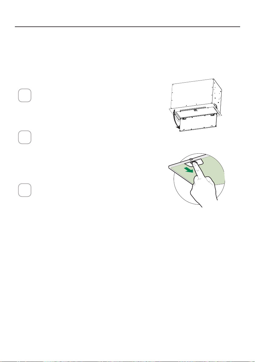
61
ENTRETIEN DES FILTRES
Ouvrez le panneau en le tirant vers
le bas. Retirez le ltre en poussant le
levier vers l'arrière de l'appareil tout
en tirant vers le bas.
Lavez le ltre sans le plier. Laissez-le
sécher complètement avant de le re-
mettre en place. Si la surface du ltre
change de couleur avec le temps,
l'efcacité n'en sera pas affectée.
Pour remplacer le ltre, poussez-le
vers le haut en position tout en main-
tenant le levier en arrière, puis relâ-
chez le levier pour le verrouiller en
place.
1
2
3
ace
NETTOYAGE DES FILTRES À GRAISSE MÉTALLIQUES
Les ltres à graisse métalliques peuvent être nettoyés dans une solution
détergente chaude ou lavés au lave-vaisselle.
Ils doivent être nettoyés tous les 2mois d'utilisation, ou plus fréquemment
si l'utilisation est particulièrement intensive.
NOTES:
• Le nettoyage dans un lave-vaisselle peut ternir la nition des ltres à
graisse en métal.
• Assurez-vous que les ltres sont complètement secs avant de les réinstal-
ler dans la hotte.
NETTOYAGE DES SURFACES EXTÉRIEURES
Veuillez noter que les abrasifs et les agents de récurage peuvent rayer les
nitions de la hotte et ne doivent pas être utilisés pour nettoyer les surfaces
de nition.
Instructions de nettoyage de la nition en acier inoxydable:
Nettoyez les surfaces extérieures avec un nettoyant pour acier inoxydable
disponible dans le commerce.

62
Ouvrez le panneau en le
tirant vers le bas. Retirez le
ltre en poussant le levier
vers l'arrière de l'appareil
tout en tirant vers le bas.
Retirez le filtre à charbon
saturé en le tournant dans
le sens antihoraire (vers
l’arrière) jusqu’à ce qu’il se
déverrouille du boîtier du
moteur et retirez-le latéral-
ement.
Pour réinsérer chaque filtre
à charbon, placez-le contre
le côté du ventilateur et
poussez-le vers l’intérieur.
Tournez ensuite le filtre à
charbon dans le sens horaire
(vers l’avant) jusqu’à ce qu’il
s’enclenche.
1
2
3
REMPLACEMENT DU FILTRE À CHARBON ACTIF
Les ltres à charbon actif ne sont pas lavables et ne peuvent pas être rég-
énérés, et doivent être remplacés environ tous les 4mois de fonctionnement,
ou plus fréquemment en cas d'utilisation intensive.
REMPLACEMENT DE L'ÉCLAIRAGE
Les lumières LED doivent être remplacées par un service agréé Faber.
ace
W
W
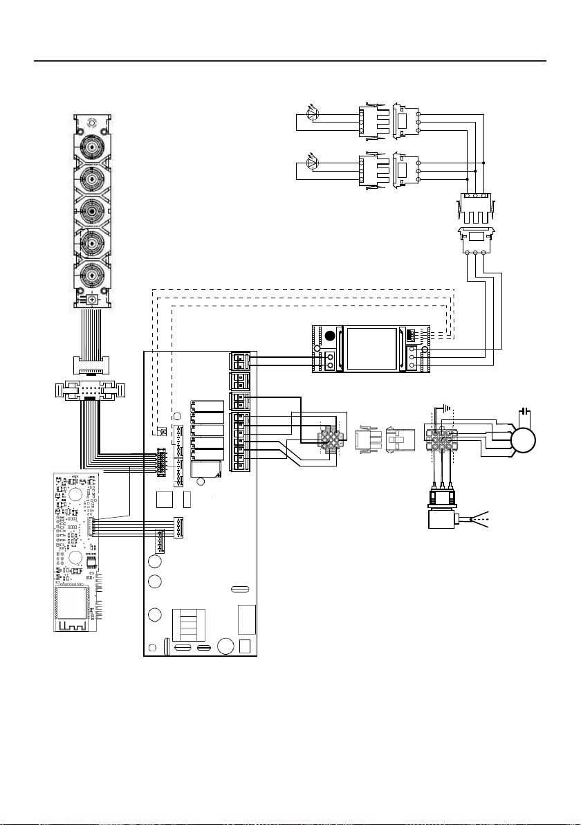
63
SCHÉMA DE CÂBLAGE
0123456789
H90_1008
01
Drawing N : Rev :
Modif. by
These drawings and specifications are the property of Franke Technology and
Trademartk Ltd and shall not be reproduced.copied or trasferred to any third party
without the prior written permission of Franke Tecnology and Trandemark Ltd.
Switzerland.It is strictly prohibited to get quotes from the drawing or bring
modifications without the prior written conset of franke Techology and Trademark
Doc.status
Modification description
Approved date
WIRING DIAGR.M8-4V ATF WI-FI 10W CL.I
Approved by
Denomination
Doc Type
Creation date
30/05/2022
FABER Corrado
Created by
991.0682.386
Code
220-240V 50-60HZ
PIN 1
PIN 3
PIN 9
PIN 7
USER INTERFACE
PIN 1
PIN 3
PIN 9
PIN 7
BRW
PNK
L-B
BLU
WHT
GRY
BLK
SEC.
ELECTRONIC
TRNSFORMER
L N
GRY
WHT
BLK
RED
M8-4V
BRW
ORG
BLK
GRY
WHT
BLU
BRW
L-B
Y-G
.
BLK
.
RED
+
GRY
RED
BLK
GRY
3
2
1
3
2
1
(-)
3
3
WHT
(-)
2
2
BLK
?led1
(+)
1
1
GRY
(-)
3
3
WHT
(-)
2
2
BLK
(+)
1
1
GRY
ORG
ORG

64
GARANTIE
Garantie Franke Home Solutions pour les produits de marque Franke et Faber en vigueur le 1ermars2022
Aux États-Unis, au Canada et en Amérique latine, Franke garantit les produits de la marque Faber contre les défauts de
fabrication des matériaux et de la fabrication lorsqu’ils sont achetés auprès d’un revendeur agréé Franke ou Faber conformément
aux garanties spécifiques aux produits détaillées dans le présent document (chacune, une «garantie» et collectivement, les
«garanties»). Les produits doivent être correctement installés, conformément aux instructions d’installation de Franke, dans leur
installation d’origine, et utilisés dans des applications de cuisine résidentielles intérieures normales. Tout produit ou composant
qui a été modifié ou altéré par rapport à son état d’origine annulera la garantie. Les garanties Franke pour les produits de marque
Faber sont limitées à l’acheteur d’origine et ne sont pas transférables. Ces garanties n’incluent pas les produits achetés auprès de
revendeurs non agréés, les produits obsolètes ou abandonnés, ou les produits qui étaient des modèles précédemment affichés.
Tous les problèmes avec les produits installés sont considérés comme des demandes de garantie et ne sont pas soumis à la
politique de retour. Franke se réserve le droit d’inspecter tout produit Franke/Faber signalé comme défectueux en vertu d’une
réclamation au titre de la garantie et de l’installation d’origine avant de fournir un produit et/ou un composant de remplacement.
Toutes les décisions sont finales. La responsabilité de Franke ne pourra en aucun cas dépasser le montant du prix d’achat initial.
Les garanties ne couvrent pas, et Franke ne sera pas tenue responsable, de tout dommage aux produits ou composants résultant
d’une mauvaise utilisation ou d’un abus, de dommages accidentels, d’une usure normale telle que des éraflures, des rayures ou
d’une réduction/décoloration du fini, d’une installation incorrecte, d’une utilisation anormale, d’une négligence, des dommages
causés par un entretien ou un nettoyage inapproprié. Les dommages causés par des impuretés, des produits chimiques corrosifs
ou des actes indépendants de la volonté de Franke ne sont couverts par aucune garantie. Les appels de service pour corriger
l’installation d’une hotte de cuisinière, les instructions sur la façon de faire fonctionner une hotte de cuisinière, pour remplacer ou
réparer les fusibles de la maison ou pour corriger le câblage ou la plomberie de la maison ne sont couverts par aucune garantie.
Les appels de service pour réparer ou remplacer les ampoules, les fusibles ou les filtres de la hotte de cuisinière et ces coûts de
pièces consommables sont également exclus de la couverture de la garantie. Une installation non conforme aux codes électriques
ou de plomberie ou à la documentation Franke/Faber n’est couverte par aucune garantie. Les pièces de rechange ou les coûts de
main-d’œuvre de réparation pour les unités utilisées à l’extérieur des États-Unis, du Canada ou de l’Amérique latine, y compris les
hottes de cuisinière Franke/Faber non approuvées UL ou C-UL ou NOM, sont exclus de la couverture de la garantie. Les frais de
déplacement et de transport pour l’entretien dans des endroits éloignés et les frais de ramassage et de livraison ne sont couverts
par aucune garantie. Les hottes de cuisinière Franke/Faber doivent toujours être entretenues à domicile dans leur installation
d’origine.
Les remplacements de produits Franke/Faber n’incluent pas la responsabilité pour les retards de projet. Les remplacements de
produits ne sont pas garantis comme étant des remplacements exacts. Si le produit d’origine n’est pas disponible au moment
de la demande de garantie, à la discrétion de Franke, les produits de remplacement seront de taille, de matériau et de valeur
similaires. Tout produit ou composant qui a été modifié ou altéré par rapport à son état d’origine annulera la garantie.
Les garanties n’autorisent pas le recouvrement des dommages indirects ou consécutifs tels que la perte d’utilisation, le retard,
les dommages matériels ou autres dommages consécutifs, et Franke décline toute responsabilité pour ces dommages. Chaque
garantie est limitée aux conditions énoncées dans le présent document et à la période de garantie applicable spécifiée dans le
présent document et est exclusive. À L’EXCEPTION DES GARANTIES ÉNONCÉES DANS LE PRÉSENT DOCUMENT, FRANKE
N’OFFRE AUCUNE GARANTIE CONCERNANT LES PRODUITS, Y COMPRIS, MAIS SANS S’Y LIMITER, (1) TOUTE GARANTIE DE
QUALITÉ MARCHANDE, (2) GARANTIE D’ADÉQUATION À UN USAGE PARTICULIER, (3) GARANTIE DE TITRE DE PROPRIÉTÉ,
OU (4) GARANTIE CONTRE LA VIOLATION DES DROITS DE PROPRIÉTÉ INTELLECTUELLE D’UN TIERS, QU’ELLE SOIT
EXPRESSE OU IMPLICITE PAR LA LOI, LE COURS DES AFFAIRES, LE COURS DE L’EXÉCUTION, L’USAGE DU COMMERCE OU
AUTREMENT. AVIS DE NON-RESPONSABILITÉ LÉGALE, VEUILLEZ
LIRE ATTENTIVEMENT. Franke Kitchen SystemsLLC vous fournit les informations ci-dessus en tant que service public à nos
clients. En accédant à ces informations et en les utilisant, vous acceptez ce qui suit et vous vous conformez à toutes les lois
applicables. Si vous n’êtes pas d’accord avec ces termes et conditions, n’utilisez pas ces informations. Bien que nous essayions de
maintenir l’information à jour, des changements peuvent avoir eu lieu depuis sa création. Contactez votre directeur régional ou le
service client pour vérifier les informations concernant les programmes Franke Kitchen SystemsLLC et leur utilisation par vous.
Garantie limitée des hottes de cuisinière Franke/Faber:
Les hottes de cuisinière Franke/Faber sont garanties contre tout défaut de matériaux ou de fabrication pour l’acheteur d’origine
pendant une période de deux(2) ans à compter de la date d’achat d’origine lorsqu’elles sont utilisées dans des applications
intérieures résidentielles normales. Cette garantie couvre la main-d’œuvre et les pièces de rechange. Franke, à sa discrétion, peut
réparer ou remplacer le produit ou les composants nécessaires pour remettre le produit en bon état de fonctionnement.
65
Cette garantie remplace toutes les autres garanties, expresses ou implicites. Aucun employé, représentant
commercial sur le terrain ou distributeur n’est autorisé à donner des garanties au nom de Franke Kitchen
Systems, LLC.
Pour faire une réclamation au titre de la garantie d’un produit installé, veuillez contacter Franke aux
coordonnées fournies ci-dessous. Toutes les réclamations de garantie doivent inclure les éléments suivants
pour le traitement:
1. Preuve d’achat auprès d’un revendeur agréé Franke ou Faber
2. Nom, adresse (ville, état, code postal) de l’acheteur d’origine, adresse de courrier électronique et
numéro de téléphone
3. Modèle et numéro de série Franke/Faber
4. Date d’installation
5. Description du défaut
6. Photos du défaut
En Amérique du Nord et en Amérique Latine:
Franke Home Solutions
À l’attention de: Warranty Department
800 Aviation Parkway
Smyrna, TN 37167
HS-Warranty.US@Franke.com
Raison sociale:
Franke Kitchen Systems LLC

66
CONTENIDOS
Sección Página
Instrucciones importantes de seguridad 67
Dimensiones de la campana extractora 70
Requisitos de altura para la instalación 71
Piezas 72
Herramientas necesarias 74
Opciones del método de ventilación por conductos 75
Montaje de la campana extractora
76
Elija Su Método De Conductos
80
Conexión de la electricidad
83
Operación de los controles
85
Aplicación Faber Cloud
91
Mando a distancia
92
Limpieza del acero inoxidable
92
Cuidado de los ltros
93
Sustitución de la iluminación
94
Diagrama de cableado
95
Garantía
96

67
INSTRUCCIONES IMPORTANTES DE SEGURIDAD
LEA Y GUARDE ESTAS INSTRUCCIONES ANTES DE EMPEZAR A
INSTALAR ESTA CAMPANA EXTRACTORA
ADVERTENCIA: - PARA REDUCIR EL RIESGO DE INCENDIO POR GRASA EN LA ENCIMERA:
a) Nunca deje las unidades de supercie desatendidas en ajustes altos. Los hervores causan humo y der-
rames de grasa que pueden encenderse. Caliente los aceites lentamente en la posición baja o media.
b) Siempre ENCIENDA la campana cuando cocine a fuego alto o cuando amee alimentos (por ejemplo,
Crepes Suzette, Cherries Jubilee, Peppercorn Beef Flambé).
c) Limpie los ventiladores con frecuencia. No se debe permitir que la grasa se acumule en el ventilador
o en el ltro.
d) Utilice el tamaño de sartén adecuado. Utilice siempre utensilios de cocina apropiados para el tamaño
de la supercie del elemento.
ADVERTENCIA: - PARA REDUCIR EL RIESGO DE LESIONES A LAS PERSONAS EN CASO DE INCENDIO
DE LA GRASA DE LA ENCIMERA, OBSERVE LO SIGUIENTE*:
a) APAGUE LAS LLAMAS con una tapa ajustada, una bandeja para galletas o una bandeja metálica, y luego
apague el quemador. TENGA CUIDADO PARA EVITAR QUEMADURAS. Si las llamas no se apagan
inmediatamente EVACÚE Y LLAME AL DEPARTAMENTO DE BOMBEROS.
b) NUNCA AGARRE UNA SARTÉN EN LLAMAS - Puede quemarse.
c) NO UTILICE AGUA, incluyendo paños de cocina o toallas mojadas - se producirá una violenta explosión
de vapor.
d) Utilice un extintor SOLO si:
1. Sabe que tiene un extintor de Clase ABC y ya sabe cómo manejarlo.
2. El fuego es pequeño y está contenido en la zona donde se inició.
3. Se está llamando a los bomberos.
4. Puede combatir el fuego de espaldas a una salida.
* Basado en " Consejos de Seguridad contra Incendios en la Cocina" publicado por la NFPA
ADVERTENCIA - PARA REDUCIR EL RIESGO DE INCENDIO O DESCARGA ELÉCTRICA, no utilice este
ventilador con ningún dispositivo de control de velocidad de estado sólido.
ADVERTENCIA - PARA REDUCIR EL RIESGO DE INCENDIO, DESCARGA ELÉCTRICA O LESIONES A LAS
PERSONAS, OBSERVE LO SIGUIENTE:
1. Utilice esta unidad solo de la manera prevista por el fabricante. Si tiene alguna pregunta, póngase
en contacto con el fabricante.
2. Antes de realizar el mantenimiento o la limpieza de la unidad, desconecte la alimentación en el panel
de servicio y bloquee los medios de desconexión de servicio para evitar que la alimentación se co-
necte accidentalmente. Cuando los medios de desconexión de servicio no puedan bloquearse, je de
forma segura un dispositivo de advertencia prominente, como una etiqueta, en el panel de servicio.
PRECAUCIÓN: Solo para uso General de Ventilación. No lo utilice para expulsar materiales y vapores
peligrosos o explosivos.
ADVERTENCIA - PARA REDUCIR EL RIESGO DE INCENDIO, DESCARGA ELÉCTRICA O LESIONES A LAS
PERSONAS, OBSERVE LO SIGUIENTE:
1. Los trabajos de instalación y cableado eléctrico lo deben realizar persona(s) cualicada(s) de
conformidad con todos los códigos y normas aplicables, incluyendo la construcción de evaluación
contra incendios.
2. Se necesita suciente aire para una combustión adecuada y para la evacuación de los gases a través
del conducto de humos (chimenea) de los equipos de combustión para evitar la explosión del aire
en retroceso. Siga las directrices y las normas de seguridad del fabricante del equipo de calefacción,
como las publicadas por la Asociación Nacional de Protección contra Incendios (NFPA) y la Sociedad
Americana de Ingenieros de Calefacción, Refrigeración y Aire Acondicionado (ASHRAE), así como
las autoridades de los códigos locales.

68
TODAS LAS APERTURAS DE LA PARED Y DEL SUELO DONDE SE INSTALE LA
CAMPANA EXTRACTORA DEBEN ESTAR SELLADAS.
Esta Campana Extractora requiere un espacio libre de al menos 24" entre la parte inferior de la Campana
Extractora y la supercie de cocción o encimera. Esta campana ha sido aprobada por UL a esta distancia
de la encimera.
Esta distancia mínima puede ser mayor dependiendo de los códigos de construcción locales. Para encimeras
de gas y cocinas combinadas, se recomienda un mínimo de 30" y es posible que esto sea necesario.
Los armarios superiores a ambos lados de esta unidad deben estar a un mínimo de 18" por encima de la
supercie de cocción o de la encimera. Consulte las instrucciones de instalación de la placa de cocción o
de la cocina dadas por el fabricante antes de hacer cualquier recorte.
INSTALACIÓN EN CASAS MÓVILES La instalación de esta campana extractora debe cumplir con las Normas
de Seguridad y Construcción de Casas Móviles, Título 24 CFR, Parte 3280 (anteriormente Norma Federal para
la Seguridad y Construcción de Casas Móviles, Título 24, HUD, Parte 280). Consulte los Requisitos Eléctricos
• El sistema de ventilación DEBE terminar en el exterior de la vivienda.
• NO termine los conductos en un ático u otro espacio cerrado.
• NO utilice tapas de pared de 4" tipo lavadero.
• No se recomienda utilizar conductos exibles.
• NO obstruya el ujo de aire de combustión y ventilación.
• El incumplimiento de los requisitos de ventilación puede provocar un incendio.
¡ADVERTENCIA
!
REQUISITOS DE VENTILACIÓN
Determine qué método de ventilación es el mejor para su aplicación. La red de conductos puede
extenderse a través de la pared o del techo.
La longitud de la red de conductos y el número de codos deben reducirse al mínimo para conse-
guir un rendimiento ecaz. El tamaño de la red de conductos debe ser uniforme. No instale dos
codos juntos. Utilice cinta adhesiva para sellar todas las juntas de la red de conductos. Utilice
masilla para sellar la pared exterior o la abertura del suelo alrededor de la tapa.
No se recomienda utilizar conductos exibles. Los conductos exibles crean contrapresión
y turbulencias de aire que reducen considerablemente el rendimiento.
Asegúrese de que hay un espacio libre adecuado dentro de la pared o del suelo para el conducto
de escape antes de hacer recortes. No corte una viga o montante a menos que sea absolutamente
necesario. Si es necesario cortar una viga o un montante, debe construirse un marco de soporte.
ADVERTENCIA - Para reducir el riesgo de incendio, utilice solo conductos metálicos.
PRECAUCIÓN - Para reducir el riesgo de incendio y para evacuar el aire adecuadamente, ase-
gúrese de canalizar el aire hacia el exterior - No ventile el aire de salida en espacios dentro
de las paredes o techos ni en áticos, semisótanos o garajes.
Instalaciones para climas fríos
Debe instalarse un regulador de corriente adicional para minimizar el ujo de aire frío de retorno
y debe instalarse un interruptor térmico no metálico para minimizar la conducción de las tem-
peraturas exteriores como parte del sistema de ventilación. El regulador debe estar situado en
el lado del interruptor térmico. El interruptor debe estar lo más cerca posible del lugar donde
el sistema de ventilación entra en la parte con calefacción de la casa.
3. Al cortar o perforar la pared o el techo, no dañe el cableado eléctrico ni otros servicios ocultos.
4. Los ventiladores con conductos deben estar siempre ventilados al exterior.
69
REQUISITOS ELÉCTRICOS
Se requiere un suministro eléctrico de 120 voltios y 60 Hz de solo CA en un circuito
separado con fusible de 15 amperios. Se recomienda utilizar un fusible de retardo o
un disyuntor de circuito. El fusible debe estar dimensionado según los códigos locales
de acuerdo con la clasicación eléctrica de esta unidad, tal como se especica en la
placa de serie/clasicación ubicada en el interior de la unidad, cerca del comparti-
miento de cableado de campo.
• Esta campana extractora requiere una toma de tierra eléctrica.
• Si la tubería de agua fría está interrumpida por plástico, juntas no metálicas u otros
materiales, NO la utilice para la conexión a tierra.
• NO conecte a tierra una tubería de gas.
• NO tenga un fusible en el circuito neutro o de conexión a tierra. Un fusible en el
circuito neutro o de conexión a tierra podría provocar una descarga eléctrica.
• Consulte a un electricista cualicado si tiene dudas sobre si la campana extractora
está correctamente conectada a tierra.
• El incumplimiento de los requisitos eléctricos puede resultar en un incendio.
¡ADVERTENCIA
!

70
DIMENSIONES DE LA CAMPANA EXTRACTORA

71
MÍN. 24" SOBRE ELÉCTRICO / MÍN. 30" SOBRE GAS
REQUISITOS DE ALTURA PARA LA INSTALACIÓN
Mín. 24" Mín. 30"
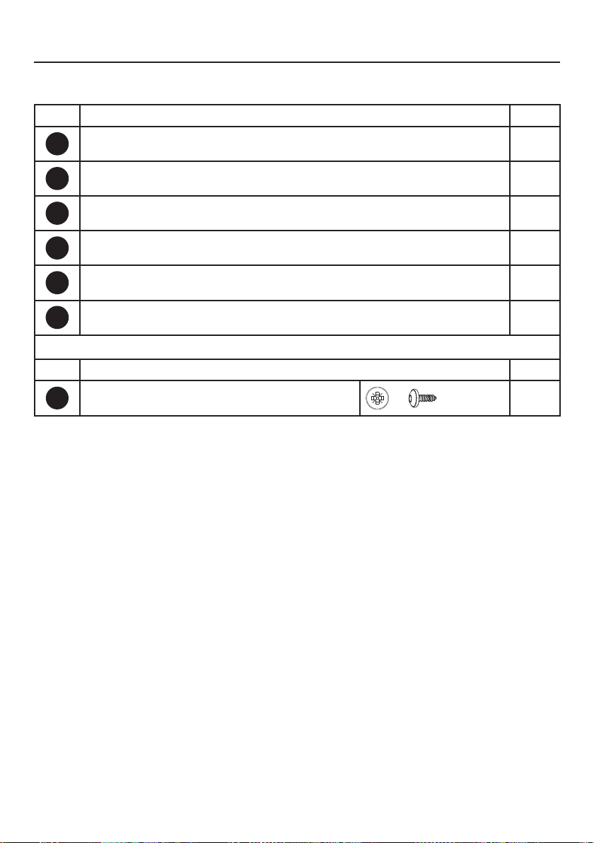
72
PIEZAS
REF. PIEZA
A
Cuerpo de la campana - Incluye controles, luz, motor, filtros
1
B
Cable de alimentación
1
C
Aleta del regulador
2
D
Anillo metálico regulador
1
E
Tapa de la rejilla de recirculación
1
F
Cubierta
2
REF. PIEZA
G
Tornillos 1/8" x 3/8"
4
PIEZAS INCLUIDAS

73
A
B
C
A
B
H1
D
P
E
F
G
G

74
PIEZAS NECESARIAS
PIEZAS (cont.)
PIEZA
Conductos metálicos redondos de 6"
Tapa de pared/techo debe comprarse por separado
HERRAMIENTAS NECESARIAS
HERRAMIENTA
Cinta Métrica
Lápiz
Taladro Eléctrico con Broca de 5/16"
Destornillador Phillips
Guantes de trabajo
ACCESORIOS DISPONIBLES
ACCESORIO SKU#
KIT DE FILTRO DE CARBÓN FILTER1
KIT DE FILTRO DE CARBÓN LAVABLE DE LARGA DURACIÓN FILTER1LL2
CAJA DE CABLEADO FIJA CAJA DE CABLES
MANDO A DISTANCIA REMORIG
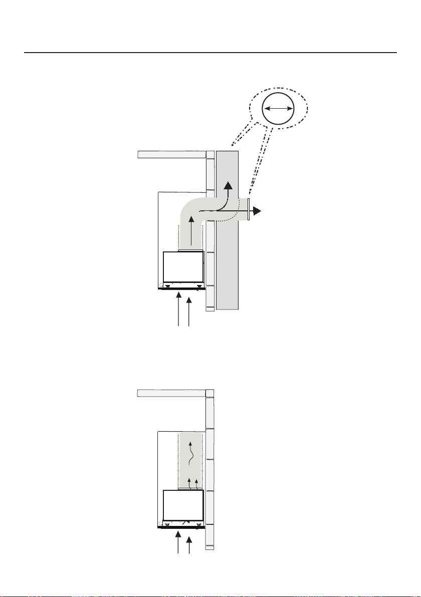
75
OPCIONES DEL MÉTODO DE VENTILACIÓN POR
CONDUCTOS
CONDUCTO CON SALIDA REDONDA DE 6":
– Vertical
– Horizontal
OPCIÓN DE RECIRCULACIÓN SIN CONDUCTOS
Requiere la compra
del accesorio de
carbón activado
Horizontal
Vertical
6"

76
Recorte la abertura en la parte inferior del mueble como se muestra en la
Figura abajo.
1
MONTAJE DE LA CAMPANA EXTRACTORA
X
Y
Min.13/16
"
Min. 3/4
"
Modelo X Y
28" 26 9/16" 10 7/16"
Profundidad
Espesor

77
Instale la campana de inserción en la abertura del mueble y acople por com-
pleto los clips de montaje laterales accionados por muelle en el mueble con
base de madera.
Después, desde abajo de la inserción mostrada en la Figura A, coloque el
tornillo en cada lado de los clips de montaje lateral.
Para bloquear la campana de inserción en su posición, apriete el tornillo de
cada clip de montaje lateral.
2
A
2x
Es posible que se
necesiten dos personas
para realizar la
instalación.

78
Inserte la cubierta
F
en cada una de las dos aberturas de los tornillos
como se muestra
3
B
2x
F
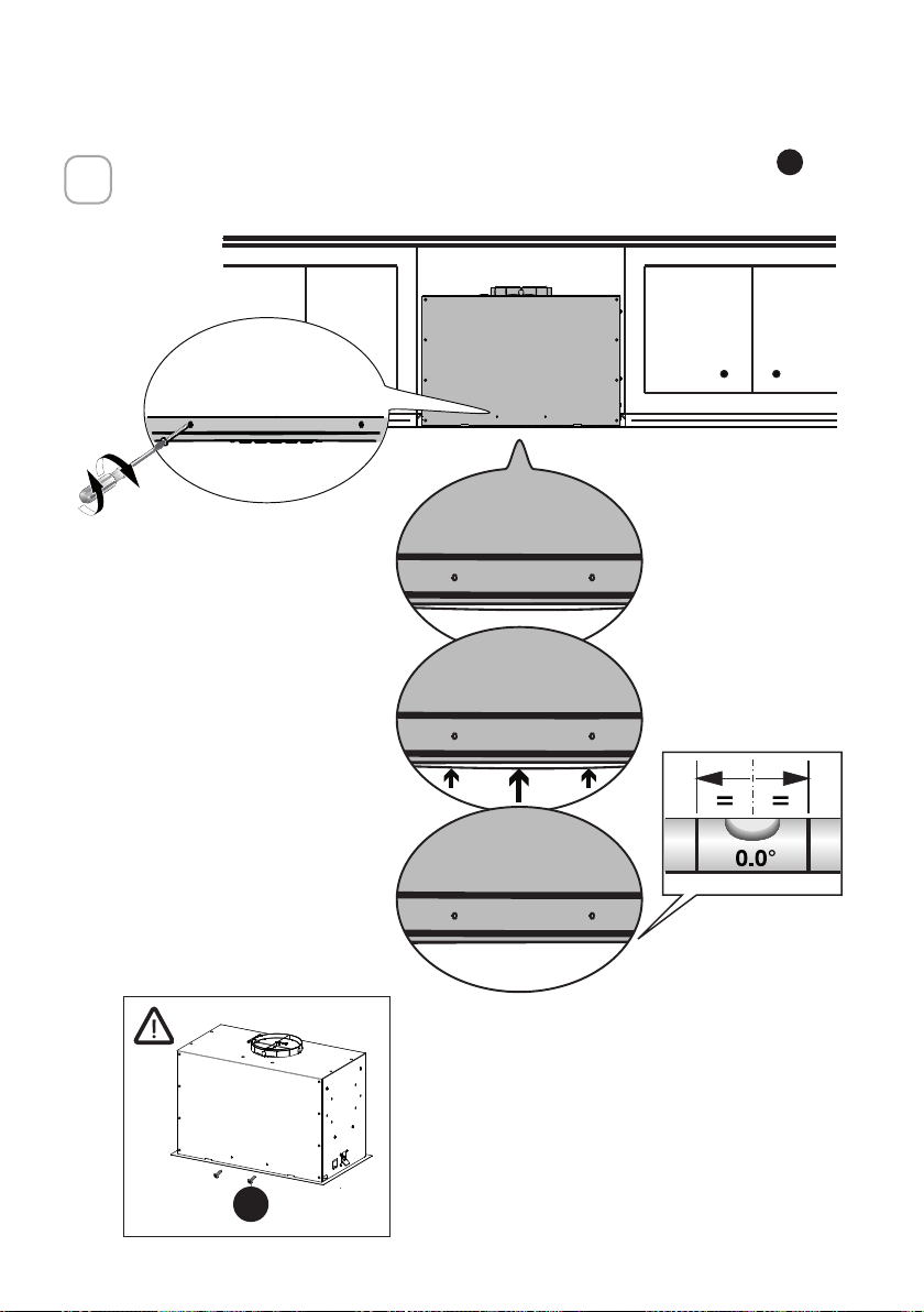
79
Si la Campana no está nivelada en la parte central, fije dos tornillos
G
como
se muestra abajo
4
A
B
G
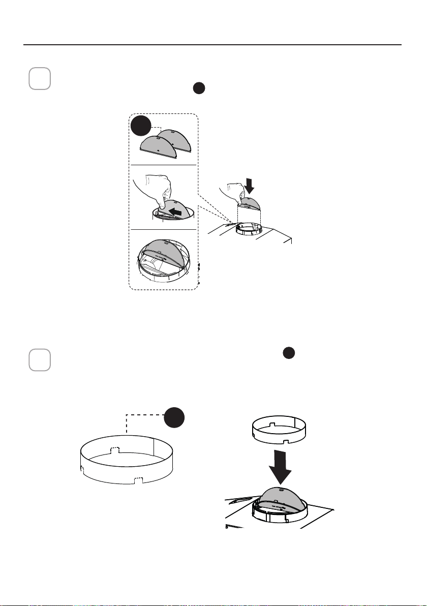
80
Rompa las 4 piezas pre-cortadas e instale el anillo
D
incluido con la cam-
pana extractora antes de conectarla a la red de conductos.
2
Instalación de ventilación por conductos
1
Instale la aleta del regulador 2
C
que se incluye con la campana extractora
como se muestra.
ELIJA SU MÉTODO DE CONDUCTOS
D
C
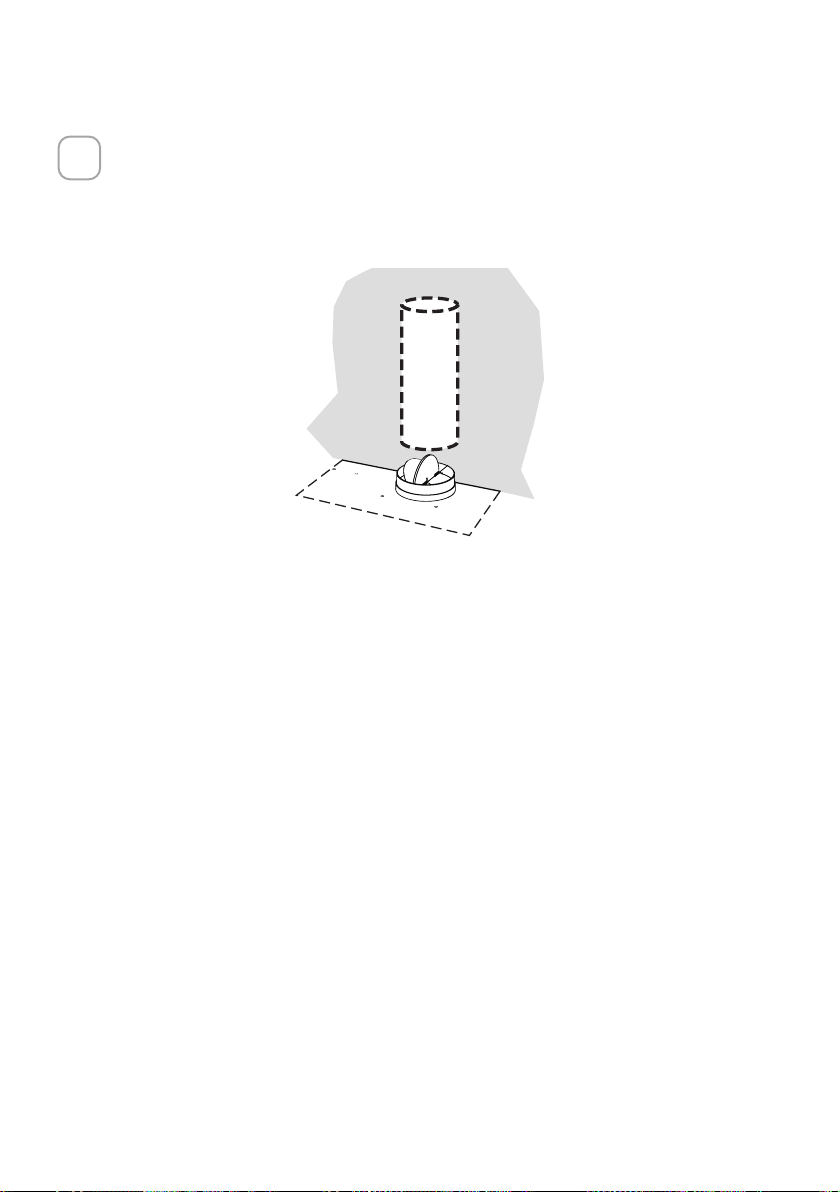
81
Instale la Tapa del Techo o de la Pared comprada por separado.
Conecte el conducto metálico de 6" a la Tapa del Techo o de la Pared y
luego fije el conducto.
3
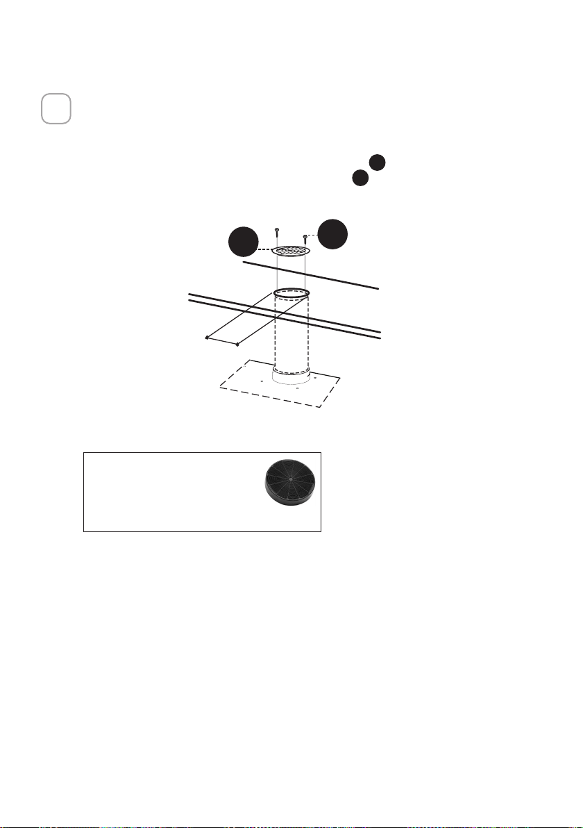
82
Opción de recirculación sin conductos
1
Para la ventilación de Recirculación sin conductos, dirija los conductos a un
lugar por encima de la campana donde la descarga se ventila de nuevo en la
habitación.
Utilice la Rejilla de Ventilación de Recirculación
E
incluida para cubrir la
abertura. Asegure la rejilla con los 2 tornillos
G
suministrados en el Kit de
Instalación.
Kit de filtro de carbón
requerido sku #FILTER1
Kit de filtro de carbón
duradero sku #FILTER1LL2
(se adquiere por separado)
´
E
G
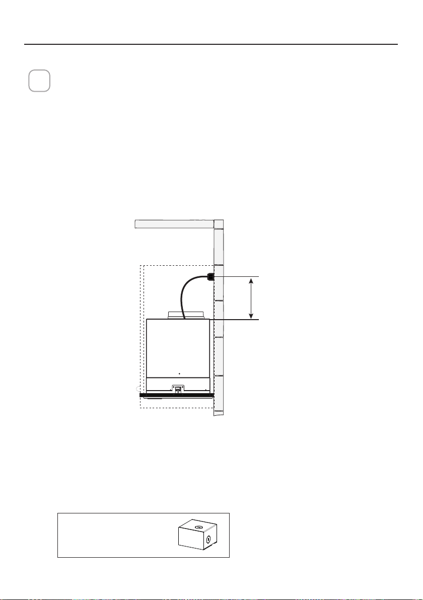
83
CONEXIÓN DE LA ELECTRICIDAD
INSTALACIÓN ELÉCTRICA CON CABLE DE CONEXIÓN
INSTRUCCIONES PARA LA CONEXIÓN A TIERRA Este aparato debe estar conecta-
do a tierra. En caso de que se produzca un cortocircuito eléctrico, la conexión a tier-
ra reduce el riesgo de descarga eléctrica al proporcionar un cable de escape para
la corriente eléctrica. Este aparato está equipado con un cable que tiene un hilo de
conexión a tierra con un enchufe de conexión a tierra. El enchufe debe conectarse a
una toma de corriente que esté correctamente instalada y conectada a tierra.
ADVERTENCIA - Una conexión a tierra inadecuada puede suponer un riesgo de
descarga eléctrica.
Consulte a un electricista cualificado si las instrucciones de conexión a tierra no se
entienden completamente, o si existen dudas sobre si el aparato está correctamente
conectado a tierra.
No utilice un cable alargador. Si el cable de alimentación es demasiado corto, haga
que un electricista cualificado instale una toma de corriente cerca del aparato.
1
ADVERTENCIA - "El cable de alimentación deberá ser accesible para su ins-
pección después de la instalación".
Max. 33 7/16”
Accesorio de caja de
cables de conexión directa
sku # WIREBOX
(se adquiere por separado)
INSTALACIÓN ELÉCTRICA CON CAJA DE CABLEADO OPCIONAL
Para instalación de cableado permanente-Utilizar solo con el kit de caja de cableado
de la campana extractora listada
sku # WIREBOX, fabricado por Faber
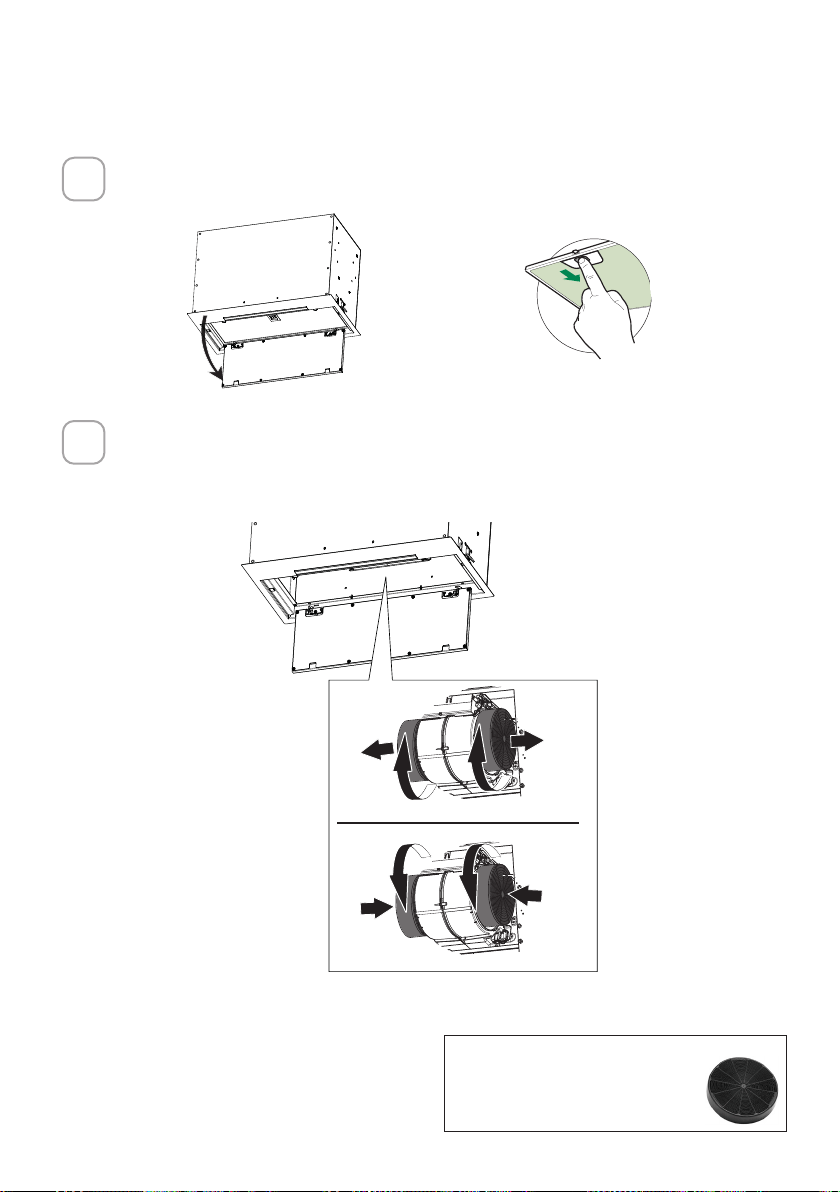
84
Abra el panel tirando de él hacia abajo. Retire el ltro para grasa, empujan-
do la tapa hacia la parte trasera de la unidad mientras tira hacia abajo.
Conecte cada filtro de carbón a la rejilla negra de cada lado del soplador.
Pulse firmemente el filtro de carbón hacia la rejilla negra del lateral del
ventilador y gire el filtro hacia la derecha (hacia la parte delantera del
extractor de inserción) hasta que se quede fijo en su posición. Gire hacia la
izquierda (hacia la parte trasera del extractor de inserción) para quitarlo.
Accesorio de filtro de carbón
activado requerido - sku sku
#FILTER1 o #FILTER1LL2
PARA LA OPCIÓN DE RECIRCULACIÓN SIN CONDUCTOS
1
2
ace
W
W

85
OPERACIÓN DE LOS CONTROLES
PARA OBTENER MEJORES RESULTADOS
Ponga en marcha la campana extractora varios minutos antes de cocinar
para desarrollar un flujo de aire adecuado. Deje que la campana extractora
funcione durante varios minutos después de terminar de cocinar para elimi-
nar todo el humo y los olores de la cocina.
A - LUCES
B - POTENCIA
C - VELOCIDAD 2
D - VELOCIDAD 3
E - INTENSIVO
F - LED
A - LUCES - Las luces tienen 3 niveles - alto, medio,
apagado - presione el botón de luz para cambiar los
niveles. Es posible cambiar la intensidad de la luz
cíclicamente. Mediante pulsaciones prolongadas y
separadas, es posible variar el tono de la luz entre
"cálido" y "frío".
BOTÓN FUNCIÓN
INDICADOR
B - POTENCIA: Una pulsación rápida enciende/apaga
el motor a la velocidad uno
B - VELOCIDAD 2: Una pulsación rápida
enciende el motor a la velocidad dos
Todos los LED parpa-
dean dos veces (alarma
activada). Todos los LED
se encienden durante 1
segundo (alarma desac-
tivada)
B - VELOCIDAD 3: Una pulsación rápida enciende el
motor a la velocidad tres
Reinicio de la alarma del filtro para grasa y/o del
filtro de carbón - Una pulsación larga con el motor
y las luces apagadas para reiniciar las alarmas de
lavado del filtro
Todos los LED parpa-
dean 3 veces
Activar / Desactivar la alarma del filtro de
carbón vegetal - Una pulsación larga con las
luces encendidas y el motor apagado activará
o desactivará la alarma de carbón vegetal.
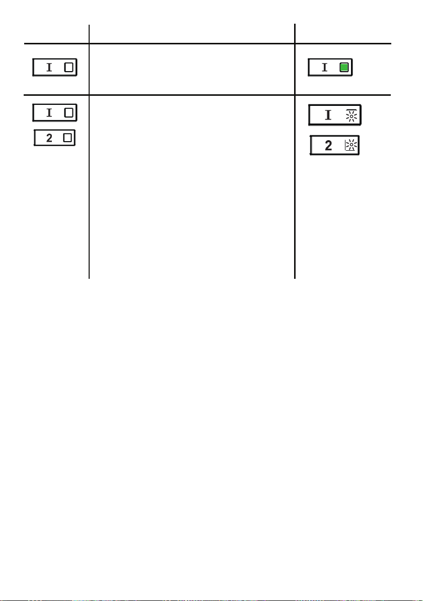
86
E - NIVEL INTENSIVO 1: Una pulsación
rápida hará funcionar el nivel de velocidad
intensivo 1 durante 6 minutos.
BOTÓN FUNCIÓN
INDICADOR
Alarma del filtro para grasa - Si los
botones de velocidad dos e intensiva están
encendidos, significa que la alarma de
saturación del filtro para grasa está activada
y los filtros para grasa deben ser lavados. La
alarma se enciende después de 100 horas de
funcionamiento.
Alarma del filtro de carbón vegetal: si
se activa la alarma, las luces de velocidad
dos e intensiva parpadearán. Esto significa
que los filtros de carbón vegetal deben ser
reemplazados Y los filtros para grasa deben
ser lavados. La alarma del filtro de carbón
se enciende después de 200 horas de
funcionamiento.

87
INFORMACIÓN SOBRE WI-FI
Este dispositivo cumple con la parte 15 de las normas de la FCC. El funcionamiento
está sujeto a las dos condiciones siguientes: (1) Este dispositivo no puede
causar interferencias perjudiciales, y (2) este dispositivo debe aceptar cualquier
interferencia recibida, incluidas las que puedan causar un funcionamiento no
deseado.
Nota: Este equipo ha sido probado y se ha comprobado que cumple con los
límites de un dispositivo digital de clase B, de acuerdo con la parte 15 de las
normas de la FCC. Estos límites están diseñados para proporcionar una protección
razonable contra las interferencias perjudiciales en una instalación residencial.
Este equipo genera, utiliza y puede irradiar energía de radiofrecuencia y, si no se
instala y utiliza según las instrucciones, puede causar interferencias perjudiciales
en las comunicaciones por radio. Sin embargo, no se puede garantizar que no se
produzcan interferencias en una instalación concreta.
Si este equipo causa interferencias perjudiciales en la recepción de radio o
televisión, lo cual puede determinarse apagando y encendiendo el equipo, se invita
al usuario a intentar corregir la interferencia tomando una o más de las siguientes
medidas:
- Reoriente o reposicione la antena receptora.
- Aumente la separación entre el equipo y el receptor.
- Conecte el equipo a una toma de corriente de un circuito distinto al que está
conectado el receptor.
- Consulte a su distribuidor o a un técnico de radio/televisión con experiencia para
que le ayude.
Las modificaciones o alteraciones de este producto no autorizadas por Faber
pueden invalidar la compatibilidad electromagnética (EMC) y la conformidad
inalámbrica y denegar el permiso de uso del producto.
Este producto demostró el cumplimiento de la compatibilidad electromagnética
en condiciones que incluían el uso de dispositivos periféricos compatibles y cables
blindados entre los componentes del sistema. Es importante utilizar periféricos
compatibles y cables apantallados entre los componentes del sistema para reducir
la posibilidad de causar interferencias en radios, televisores y otros dispositivos
electrónicos.
Exposición a la energía de radiofrecuencia. La potencia de salida radiada de este
dispositivo cumple con los límites de exposición a la radiofrecuencia de la FCC y el
IC. Este dispositivo debe utilizarse con una distancia mínima de separación de 20
cm (8 pulgadas) entre el equipo y el cuerpo de una persona.
Información sobre los aparatos conectados
Contiene FCC ID:2AC7Z-ESPWROOM32D
Contiene IC:21098-ESPWROOM32D
Modelo: ESP32-WROOM-32D
CAN ICES-003(B)/NMB-003(B)
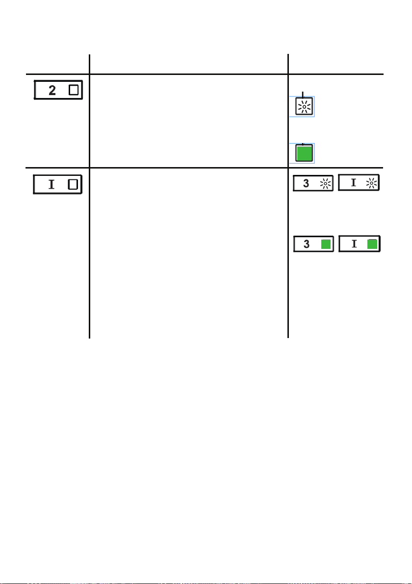
88
BOTÓN FUNCIÓN
INDICADOR
Activar / Desactivar la función de conexión
Wi-Fi.
Una pulsación larga del botón de velocidad 2
con el motor y las luces apagadas para activar/
desactivar el WI-FI.
Nota: la función Wi-Fi se activa
automáticamente cuando el usuario solicita el
procedimiento de configuración Wi-Fi.
Conexión
al router
inalámbrico de
casa en curso.
Conexión Wi-Fi
activada.
Iniciar la configuración del Wi-fi
Una pulsación larga con el motor y las
luces apagadas para entrar o terminar el
procedimiento de configuración del Wi-Fi.
Antes de iniciar el procedimiento, utilice la
aplicación Faber Cloud para registrarse en el
sistema IOT Faber. A continuación, siga las
instrucciones para añadir un nuevo dispositivo y
registrar su router inalámbrico doméstico.
Si el procedimiento no se completa con éxito
en unos pocos minutos, detenga el proceso de
configuración manteniendo el botón intensivo
durante 3 segundos. Mantenga el botón de
nuevo durante 3 segundos para iniciar el
proceso. La campana detendrá el proceso de
configuración del Wi-fi si no se completa con
éxito en 15 minutos.
La instalación está
en curso
F - LED
Cuando la
configuración
se ha
terminado los
LED permanecen
encendidos
durante 2
segundos.
CONEXIONES SOBRE WI-FI
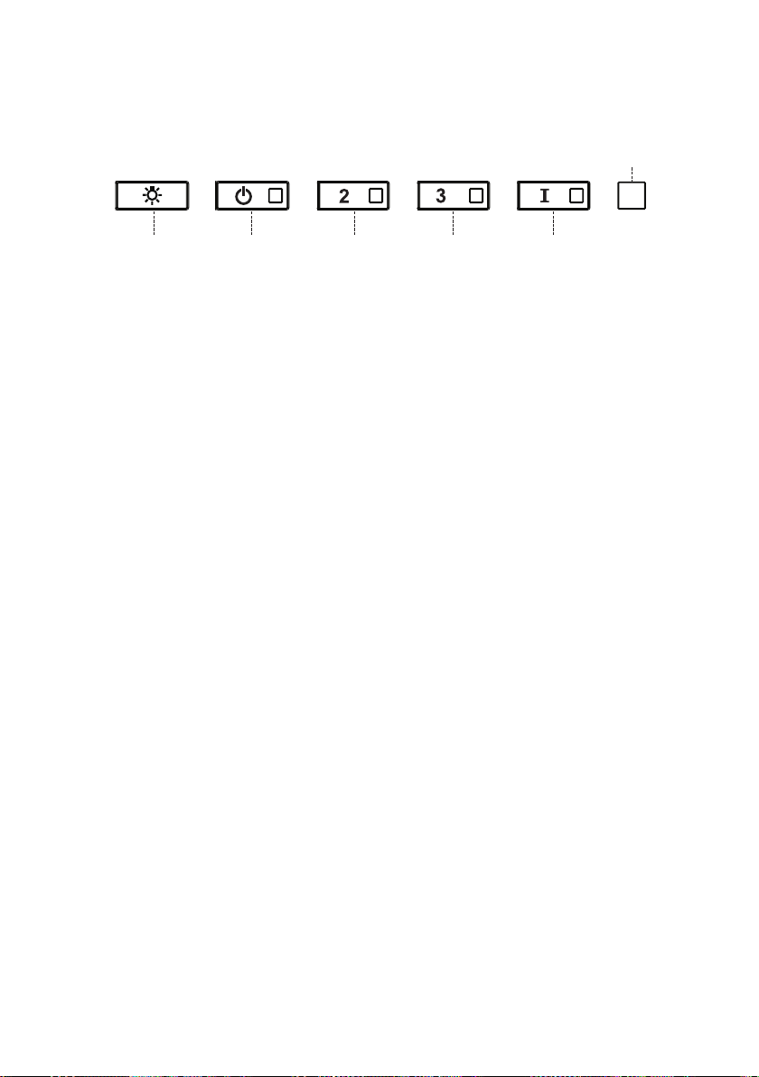
89
AJUSTE DE CFM < 295CFM
Para iniciar el proceso asegúrese de que las luces de la campana están
encendidas y el motor está apagado.
1) Mantenga pulsado T1 durante 7 segundos hasta que todos los LED
parpadeen.
2) Cuando el parpadeo se haya detenido, pulse T1.
3) El botón T1 parpadeará una vez, luego pulse el botón T1 de nuevo para
confirmar su elección (pulsado antes de 10 segundos)
4) Los cuatro LED parpadearán de nuevo para confirmar que ha terminado
el ajuste de CFM a menos de 295 CFM.
5) Coloque la etiqueta de menos de 295 CFM en el interior de la campana
(detrás de los filtros para grasa) cerca de la etiqueta de clasificación
para la inspección y en el frente de su manual de instalación/usuario.
6) Para confirmar su ajuste para la inspección, los botones T1 y T2 siempre
harán funcionar la campana a la misma velocidad. La velocidad más alta
(T3) y la velocidad intensiva (T4), también dejarán de funcionar.
Nota: Los botones T2 y T3 funcionarán ahora al mismo nivel y la velocidad
intensiva se desactivará.
Atención: Cuando se ha completado el ajuste de menos de 295 CFM, ya no
es posible cambiar este ajuste al nivel original de CFM.
ATENCIÓN: Para un correcto funcionamiento de la APP FABER CLOUD,
una vez finalizado este procedimiento, desconecte el enchufe de la red
eléctrica y vuelva a conectarlo.

90
AJUSTE DE CFM < 395CFM
Para iniciar el proceso asegúrese de que las luces de la campana están
encendidas y el motor está apagado.
1) Mantenga pulsado T1 durante 7 segundos hasta que todos los LED
parpadeen.
2) Cuando el parpadeo se haya detenido, pulse T2
3) El botón T2 parpadeará una vez, luego pulse el botón T2 de nuevo para
confirmar su elección (pulsado antes de 10 segundos)
4) Los cuatro LED parpadearán de nuevo para confirmar que ha terminado
el ajuste de CFM a menos de 395 CFM.
5) Coloque la etiqueta de menos de 395 CFM en el interior de la campana
(detrás de los filtros de grasa) cerca de la etiqueta de clasificación para
la inspección y en el frente de su manual de instalación/usuario.
6) Para confirmar su ajuste para la inspección, la función de velocidad
intensiva, ya no funcionará.
Nota: Los botones T3 y T4 funcionarán ahora al mismo nivel y la velocidad
intensiva se desactivará.
Atención: Cuando se ha completado el ajuste de menos de 395 CFM, ya no
es posible cambiar este ajuste al nivel original de CFM.
ATENCIÓN: Para un correcto funcionamiento de la APP FABER CLOUD,
una vez finalizado este procedimiento, desconecte el enchufe de la red
eléctrica y vuelva a conectarlo.

91
APLICACIÓN FABER CLOUD
Aplicación Faber Cloud
Su campana extractora es compatible con la aplicación Faber Cloud. Todo lo que
necesita es una red Wi-Fi conectada a Internet que esté dentro del alcance de la cam-
pana extractora. Usted puede controlar todas las funciones de su campana extractora
desde cualquier lugar utilizando un dispositivo móvil o su altavoz inteligente Amazon
Alexa o Google Home. Cuando se conecta a su altavoz inteligente, puede controlar su
campana con su voz.
La aplicación Faber Cloud está disponible en dispositivos iOS que utilicen iOS 11.0 o
posterior o en dispositivos Android que utilicen la versión 8 o posterior de Android.
Visite la App Store de Apple o la Play Store de Google para obtener más información.
Su campana extractora tendrá una funcionalidad completa si no utiliza las funciones
de Wi-fi o de la aplicación Faber CLoud, ninguna de las cuales es necesaria.
Por favor, revise la Guía de inicio de conexión rápida incluida para más información.
Icono Función
5. FABER CLOUD APP
The Faber Cloud App is available for
iOS and Android smartphones and al-
lows remote access to all hood func-
tions.
Icon Function
Home page
Add new device
User profile management
Connected to Faber Wi-Fi network
Hood on/off
Lighting system management
Motor speed management
Intensive Function
24h Function
Delay Function
Automatic Function
App settings management
6. REMOTE CONTROL
• This appliance can be controlled us-
ing a remote control.
• ATTENTION: before proceeding, ac-
tivate K-Link Mode on the remote
control (see the device manual for
further details).
7. LIGHTING
• Please contact the Service Depart-
ment to change it ("Please contact
the service department to purchase
it").
8
Página de inicio
5. FABER CLOUD APP
The Faber Cloud App is available for
iOS and Android smartphones and al-
lows remote access to all hood func-
tions.
Icon Function
Home page
Add new device
User profile management
Connected to Faber Wi-Fi network
Hood on/off
Lighting system management
Motor speed management
Intensive Function
24h Function
Delay Function
Automatic Function
App settings management
6. REMOTE CONTROL
• This appliance can be controlled us-
ing a remote control.
• ATTENTION: before proceeding, ac-
tivate K-Link Mode on the remote
control (see the device manual for
further details).
7. LIGHTING
• Please contact the Service Depart-
ment to change it ("Please contact
the service department to purchase
it").
8
Agregar un nuevo dispositivo
5. FABER CLOUD APP
The Faber Cloud App is available for
iOS and Android smartphones and al-
lows remote access to all hood func-
tions.
Icon Function
Home page
Add new device
User profile management
Connected to Faber Wi-Fi network
Hood on/off
Lighting system management
Motor speed management
Intensive Function
24h Function
Delay Function
Automatic Function
App settings management
6. REMOTE CONTROL
• This appliance can be controlled us-
ing a remote control.
• ATTENTION: before proceeding, ac-
tivate K-Link Mode on the remote
control (see the device manual for
further details).
7. LIGHTING
• Please contact the Service Depart-
ment to change it ("Please contact
the service department to purchase
it").
8
Gestión de perfiles de usuario
5. FABER CLOUD APP
The Faber Cloud App is available for
iOS and Android smartphones and al-
lows remote access to all hood func-
tions.
Icon Function
Home page
Add new device
User profile management
Connected to Faber Wi-Fi network
Hood on/off
Lighting system management
Motor speed management
Intensive Function
24h Function
Delay Function
Automatic Function
App settings management
6. REMOTE CONTROL
• This appliance can be controlled us-
ing a remote control.
• ATTENTION: before proceeding, ac-
tivate K-Link Mode on the remote
control (see the device manual for
further details).
7. LIGHTING
• Please contact the Service Depart-
ment to change it ("Please contact
the service department to purchase
it").
8
Conectado a la red Wi-Fi de Faber
5. FABER CLOUD APP
The Faber Cloud App is available for
iOS and Android smartphones and al-
lows remote access to all hood func-
tions.
Icon Function
Home page
Add new device
User profile management
Connected to Faber Wi-Fi network
Hood on/off
Lighting system management
Motor speed management
Intensive Function
24h Function
Delay Function
Automatic Function
App settings management
6. REMOTE CONTROL
• This appliance can be controlled us-
ing a remote control.
• ATTENTION: before proceeding, ac-
tivate K-Link Mode on the remote
control (see the device manual for
further details).
7. LIGHTING
• Please contact the Service Depart-
ment to change it ("Please contact
the service department to purchase
it").
8
Encendido/apagado de la campana
5. FABER CLOUD APP
The Faber Cloud App is available for
iOS and Android smartphones and al-
lows remote access to all hood func-
tions.
Icon Function
Home page
Add new device
User profile management
Connected to Faber Wi-Fi network
Hood on/off
Lighting system management
Motor speed management
Intensive Function
24h Function
Delay Function
Automatic Function
App settings management
6. REMOTE CONTROL
• This appliance can be controlled us-
ing a remote control.
• ATTENTION: before proceeding, ac-
tivate K-Link Mode on the remote
control (see the device manual for
further details).
7. LIGHTING
• Please contact the Service Depart-
ment to change it ("Please contact
the service department to purchase
it").
8
Gestión del sistema de iluminación
5. FABER CLOUD APP
The Faber Cloud App is available for
iOS and Android smartphones and al-
lows remote access to all hood func-
tions.
Icon Function
Home page
Add new device
User profile management
Connected to Faber Wi-Fi network
Hood on/off
Lighting system management
Motor speed management
Intensive Function
24h Function
Delay Function
Automatic Function
App settings management
6. REMOTE CONTROL
• This appliance can be controlled us-
ing a remote control.
• ATTENTION: before proceeding, ac-
tivate K-Link Mode on the remote
control (see the device manual for
further details).
7. LIGHTING
• Please contact the Service Depart-
ment to change it ("Please contact
the service department to purchase
it").
8
Gestión de la velocidad del motor
5. FABER CLOUD APP
The Faber Cloud App is available for
iOS and Android smartphones and al-
lows remote access to all hood func-
tions.
Icon Function
Home page
Add new device
User profile management
Connected to Faber Wi-Fi network
Hood on/off
Lighting system management
Motor speed management
Intensive Function
24h Function
Delay Function
Automatic Function
App settings management
6. REMOTE CONTROL
• This appliance can be controlled us-
ing a remote control.
• ATTENTION: before proceeding, ac-
tivate K-Link Mode on the remote
control (see the device manual for
further details).
7. LIGHTING
• Please contact the Service Depart-
ment to change it ("Please contact
the service department to purchase
it").
8
Función intensiva
5. FABER CLOUD APP
The Faber Cloud App is available for
iOS and Android smartphones and al-
lows remote access to all hood func-
tions.
Icon Function
Home page
Add new device
User profile management
Connected to Faber Wi-Fi network
Hood on/off
Lighting system management
Motor speed management
Intensive Function
24h Function
Delay Function
Automatic Function
App settings management
6. REMOTE CONTROL
• This appliance can be controlled us-
ing a remote control.
• ATTENTION: before proceeding, ac-
tivate K-Link Mode on the remote
control (see the device manual for
further details).
7. LIGHTING
• Please contact the Service Depart-
ment to change it ("Please contact
the service department to purchase
it").
8
Función de retardo
5. FABER CLOUD APP
The Faber Cloud App is available for
iOS and Android smartphones and al-
lows remote access to all hood func-
tions.
Icon Function
Home page
Add new device
User profile management
Connected to Faber Wi-Fi network
Hood on/off
Lighting system management
Motor speed management
Intensive Function
24h Function
Delay Function
Automatic Function
App settings management
6. REMOTE CONTROL
• This appliance can be controlled us-
ing a remote control.
• ATTENTION: before proceeding, ac-
tivate K-Link Mode on the remote
control (see the device manual for
further details).
7. LIGHTING
• Please contact the Service Depart-
ment to change it ("Please contact
the service department to purchase
it").
8
Función 24H
5. FABER CLOUD APP
The Faber Cloud App is available for
iOS and Android smartphones and al-
lows remote access to all hood func-
tions.
Icon Function
Home page
Add new device
User profile management
Connected to Faber Wi-Fi network
Hood on/off
Lighting system management
Motor speed management
Intensive Function
24h Function
Delay Function
Automatic Function
App settings management
6. REMOTE CONTROL
• This appliance can be controlled us-
ing a remote control.
• ATTENTION: before proceeding, ac-
tivate K-Link Mode on the remote
control (see the device manual for
further details).
7. LIGHTING
• Please contact the Service Depart-
ment to change it ("Please contact
the service department to purchase
it").
8
Gestión de la configuración de la aplicación
5. FABER CLOUD APP
The Faber Cloud App is available for
iOS and Android smartphones and al-
lows remote access to all hood func-
tions.
Icon Function
Home page
Add new device
User profile management
Connected to Faber Wi-Fi network
Hood on/off
Lighting system management
Motor speed management
Intensive Function
24h Function
Delay Function
Automatic Function
App settings management
6. REMOTE CONTROL
• This appliance can be controlled us-
ing a remote control.
• ATTENTION: before proceeding, ac-
tivate K-Link Mode on the remote
control (see the device manual for
further details).
7. LIGHTING
• Please contact the Service Depart-
ment to change it ("Please contact
the service department to purchase
it").
8
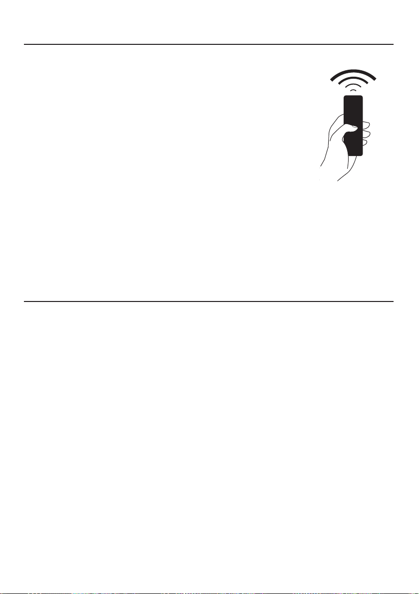
92
El mando a distancia reproduce las funciones del
panel de control de la campana. #REMORIG
MANDO A DISTANCIA (opcional)
Limpieza de las superficies exteriores:
Por favor, tenga en cuenta que los abrasivos y los agentes de fregado
pueden rayar los acabados de la campana extractora y no deben
utilizarse para limpiar las superficies acabadas.
Instrucciones para la limpieza del acabado de acero inoxidable:
Limpie las superficies exteriores con un limpiador de acero inoxidable
disponible comercialmente.
LIMPIEZA DEL ACERO INOXIDABLE
ATENCIÓN: algunas funciones puedenactivarse
solo a través del mando a distancia (consultar
el manual del dispositi-vo para más
información).

93
CUIDADO DE LOS FILTROS
Abra el panel tirando de él hacia
abajo. Retirar el ltro, empujando la
palanca hacia la parte posterior de la
unidad mientras se tira hacia abajo.
Lavar el ltro sin doblarlo. Dejarlo se-
car bien antes de volver a colocarlo. Si
la supercie del ltro cambia de color
con el tiempo, la ecacia no se verá
afectada.
Para sustituir el ltro, hay que empu-
jar el ltro hacia arriba en su posición
mientras se mantiene la palanca hacia
atrás, y luego soltar la palanca para
bloquearlo en su lugar.
1
2
3
ace
LIMPIEZA DE LOS FILTROS DE GRASA METÁLICOS
Los ltros para grasa metálicos pueden limpiarse en una solución de deter-
gente caliente o lavarse en el lavavajillas.
Deben limpiarse cada 2 meses de uso, o con mayor frecuencia si el uso es
particularmente intenso.
NOTAS:
• La limpieza en el lavavajillas puede deteriorar el acabado de los ltros
para grasa metálicos.
• Asegurarse de que los ltros están completamente secos antes de volver
a instalarlos en la campana extractora.
LIMPIEZA DE LAS SUPERFICIES EXTERIORES
Por favor, tenga en cuenta que los abrasivos y los agentes de fregado pue-
den rayar los acabados de la campana extractora y no deben utilizarse para
limpiar las supercies acabadas.
Instrucciones para la limpieza del acabado de acero inoxidable:
Limpie las supercies exteriores con un limpiador de acero inoxidable dis-
ponible comercialmente.

94
Abra el panel tirando de él
hacia abajo. Retirar el ltro,
empujando la palanca hacia
la parte posterior de la uni-
dad mientras se tira hacia
abajo.
Retire el filtro de carbón
saturado girándolo hacia la
derecha (hacia atrás) hasta
que se desbloquee de la car-
casa del motor y tire hacia el
lateral.
Para volver a colocar cada
filtro de carbón, colóquelo
contra el lateral del ven-
tilador y presiónelo hacia
dentro. Después gire el filtro
de carbón hacia la derecha
(hacia delante) hasta que se
quede en su posición.
1
2
3
SUSTITUCIÓN DEL FILTRO DE CARBÓN ACTIVADO
Los ltros de carbón activado no son lavables y no pueden ser regenerados,
por lo que deben ser reemplazados aproximadamente cada 4 meses de fun-
cionamiento, o con mayor frecuencia en caso de uso intensivo.
SUSTITUCIÓN DE LA ILUMINACIÓN
Las luces LED deben ser sustituidas por el servicio técnico autorizado de
Faber.
ace
W
W

95
DIAGRAMA DE CABLEADO
0123456789
H90_1008
01
Drawing N : Rev :
Modif. by
These drawings and specifications are the property of Franke Technology and
Trademartk Ltd and shall not be reproduced.copied or trasferred to any third party
without the prior written permission of Franke Tecnology and Trandemark Ltd.
Switzerland.It is strictly prohibited to get quotes from the drawing or bring
modifications without the prior written conset of franke Techology and Trademark
Doc.status
Modification description
Approved date
WIRING DIAGR.M8-4V ATF WI-FI 10W CL.I
Approved by
Denomination
Doc Type
Creation date
30/05/2022
FABER Corrado
Created by
991.0682.386
Code
220-240V 50-60HZ
PIN 1
PIN 3
PIN 9
PIN 7
USER INTERFACE
PIN 1
PIN 3
PIN 9
PIN 7
BRW
PNK
L-B
BLU
WHT
GRY
BLK
SEC.
ELECTRONIC
TRNSFORMER
L N
GRY
WHT
BLK
RED
M8-4V
BRW
ORG
BLK
GRY
WHT
BLU
BRW
L-B
Y-G
.
BLK
.
RED
+
GRY
RED
BLK
GRY
3
2
1
3
2
1
(-)
3
3
WHT
(-)
2
2
BLK
?led1
(+)
1
1
GRY
(-)
3
3
WHT
(-)
2
2
BLK
(+)
1
1
GRY
ORG
ORG

96
GARANTÍA
La garantía de Franke Home Solutions para los productos de las marcas Franke y Faber entra en vigor el 1 de marzo de 2022
En Estados Unidos, Canadá y América Latina, Franke garantiza los productos de la marca Faber contra defectos de fabricación
en materiales y mano de obra cuando se compran a un minorista autorizado de Franke o Faber de acuerdo con las garantías
específicas del producto que se detallan en este documento (cada una, una "Garantía" y colectivamente, las "Garantías"). Los
productos deben ser instalados correctamente, según las instrucciones de instalación de Franke, en su instalación original,
y utilizados en aplicaciones normales de cocina residencial en interiores. Cualquier producto o componente que haya sido
modificado o alterado de su condición original anulará la garantía. Las garantías de Franke para los productos de la marca Faber
están limitadas al comprador original y no son transferibles. Estas garantías no incluyen los productos comprados a minoristas no
autorizados, los productos obsoletos o descatalogados, ni los productos que eran modelos de exposición anteriores. Todos los
problemas con los productos instalados se consideran reclamaciones de garantía y no están sujetos a la política de devoluciones.
Franke se reserva el derecho de inspeccionar cualquier producto Franke / Faber reportado como defectuoso en virtud de una
reclamación de garantía y la instalación original antes de proporcionar un producto y/o componente de reemplazo. Todas las
decisiones son definitivas. En ningún caso la responsabilidad de Franke superará el importe del precio de compra original.
Las garantías no cubren, y Franke no será responsable, de ningún daño a los productos o componentes derivado de un mal uso
o abuso, daños accidentales, desgaste normal como rozaduras, arañazos o reducción/descoloramiento del acabado, instalación
incorrecta, uso anormal, negligencia, daños causados por un mantenimiento o limpieza inadecuados. Los daños causados por
impurezas, productos químicos corrosivos o actos fuera del control de Franke no están cubiertos por ninguna garantía. Las
llamadas de servicio para corregir la instalación de una campana extractora, las instrucciones sobre el funcionamiento de una
campana extractora, para sustituir o reparar los fusibles de la casa o para corregir el cableado o la fontanería de la casa no están
cubiertas por ninguna Garantía. Las llamadas de servicio para reparar o sustituir las bombillas, fusibles o filtros de la campana
extractora, así como los costes de estas piezas consumibles, también están excluidos de la cobertura de la garantía. La instalación
que no esté de acuerdo con los códigos eléctricos o de fontanería o con la documentación de Franke / Faber no está cubierta
por ninguna garantía. Los costes de las piezas de repuesto o de la mano de obra de reparación de las unidades utilizadas fuera
de los Estados Unidos, Canadá o América Latina, incluidas las campanas extractoras de cocina Franke / Faber no aprobadas por
la norma UL o C-UL, están excluidos de la cobertura de la garantía. Los gastos de viaje y transporte para el servicio en lugares
remotos y los gastos de recogida y entrega no están cubiertos por ninguna Garantía. Las campanas extractoras Franke / Faber
siempre deben ser revisadas en el hogar en su instalación original.
Las sustituciones de productos Franke / Faber no incluyen la responsabilidad por los retrasos del proyecto. No se garantiza que
las sustituciones de los productos sean exactas. Si el producto original no está disponible en el momento de la reclamación de
la garantía, a opción de Franke, los reemplazos del producto serán de tamaño, material y valor similares. Cualquier producto o
componente que haya sido modificado o alterado de su condición original anulará la garantía.
Las garantías no permiten la recuperación de los daños incidentales o indirectos, como la pérdida de uso, el retraso, los daños a la
propiedad u otros daños indirectos, y Franke no acepta ninguna responsabilidad por tales daños. Cada Garantía está limitada a las
condiciones establecidas en el presente documento y al período de garantía aplicable especificado en el mismo y es exclusiva. A
EXCEPCIÓN DE LAS GARANTÍAS ESTABLECIDAS EN ESTE DOCUMENTO, FRANKE NO OFRECE NINGUNA GARANTÍA CON
RESPECTO A LOS PRODUCTOS, INCLUYENDO, PERO NO LIMITADO A, (1) CUALQUIER GARANTÍA DE COMERCIALIZACIÓN,
(2) LA GARANTÍA DE IDONEIDAD PARA UN PROPÓSITO PARTICULAR, (3) LA GARANTÍA DE TÍTULO, O (4) LA GARANTÍA
CONTRA LA VIOLACIÓN DE LOS DERECHOS DE PROPIEDAD INTELECTUAL DE UN TERCERO, YA SEA EXPRESA O
IMPLÍCITA POR LA LEY, EL DESARROLLO DE LOS NEGOCIOS, EL DESARROLLO DE LA EJECUCIÓN, EL USO DEL COMERCIO
O DE OTRA MANERA. AVISO LEGAL POR FAVOR
LEA ATENTAMENTE. Franke Kitchen Systems LLC le proporciona la información anterior como un servicio público a nuestros
clientes. Al acceder y utilizar esta información, usted acepta lo siguiente y el cumplimiento de todas las leyes aplicables. Si no está
de acuerdo con estas condiciones, no utilice esta información. Aunque intentamos mantener la información actualizada, pueden
haberse producido cambios desde su creación. Póngase en contacto con su gerente regional o con el servicio de atención al
cliente para verificar la información relativa a los programas de Franke Kitchen Systems LLC y su uso.
Garantía limitada de la campana extractora Franke / Faber:
Las campanas extractoras de Franke / Faber están garantizadas contra cualquier defecto de materiales o mano de obra
para el comprador original durante un período de dos (2) años a partir de la fecha de compra original cuando se utilizan en
aplicaciones residenciales estándar de interior. Esta garantía cubre la mano de obra y las piezas de recambio. Franke, a su elección,
puede reparar o sustituir el producto o los componentes necesarios para restablecer el producto en buenas condiciones de
funcionamiento.

97
Esta garantía sustituye a todas las demás garantías, expresas o implícitas. Ningún empleado, representante
de ventas de campo o distribuidor está autorizado a dar ninguna garantía en nombre de Franke Kitchen
Systems, LLC
Para reclamar la garantía de un producto instalado, póngase en contacto con Franke a través de la
información de contacto proporcionada a continuación. Todos los reclamos de garantía deben incluir lo
siguiente para su procesamiento:
1. Prueba de compra en un distribuidor autorizado de Franke o Faber
2. Nombre del comprador original, dirección (incluyendo ciudad, estado y código postal), dirección de
correo electrónico y número de teléfono
3. Modelo y número de serie de Franke / Faber
4. Fecha de instalación
5. Descripción del defecto
6. Fotos del defecto
En América del Norte y América Latina:
Soluciones para el hogar Franke
A la atención de: Departamento de Garantía
800 Aviation Parkway
Smyrna, TN 37167
HS-Warranty.US@Franke.com
Persona jurídica:
Franke Kitchen Systems LLC

98

99

991.0682.452_01 - 220801
D00008853_00