
Operator's Manual
ICRnFTSMnNiI
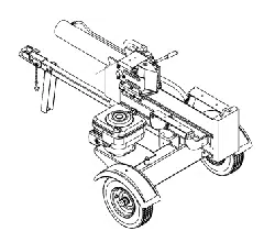
26 Ton Hydraulic
Log Splitter
Model No. 247.774500
CAUTION: Before using
this product, read this
manual and follow all
Safety Rules and
Operating Instructions.
• Safety
• Assembly
• Operation
• Maintenance
• Parts
• Espa_ol
Sears, Roebuck and Co., Hoffman Estates, IL 60179, U.S.A.
Visit our Sears website: www.sears.com/craftsman
Printed in U.S.A.
FORM NO. 770-10530A
(7/01)
Content Page Content Page
Warranty 2 Service and Adjustments 13
Safety 3 Storage 15
Assembly 5 Troubleshooting 16
Operation 7 Notes 17
Maintenance 11 Parts List 18
Limited Warranty on Craftsman Log Splitter
For one (1) year from the date of purchase, ifthis Craftsman Equipment is maintained, lubricated, and tuned up
according to the instructions to the operator's manual, Sears will repair or replace free of charge any parts found
to be defective in material or workmanship. Warranty service is available free of charge by returning Craftsman
equipment to your nearest Sears Service Center. In-home warranty service is available but a trip charge will
apply. This Warranty applies only while this product is in the United States.
This Warranty does not cover:
• Expendable items which become worn during normal use, such as spark plugs, air cleaners, belts, and oil
filters.
• Tire replacement or repair caused by punctures from outside objects, such as nails, thorns, stumps, or glass.
• Repairs necessary because of operator abuse, including but not limited to, damage caused by objects, such
as stones or metal debris, oversized stock, impacting objects that bend the frame or crankshaft, or over-
speeding the engine.
• Repairs necessary because of operator negligence, including but not limited to, electrical and mechanical
damage caused by improper storage, failure to use the proper grade and amount of engine oil, or failure to
maintain the equipment according to the instructions contained in the operator's manual.
• Engine (fuel system) cleaning or repairs caused by fuel determine to be contaminated or oxidized (stale). In
general, fuel should be used within 30 days of its purchase date.
• Equipment used for commercial or rental purposes.
TO LOCATE THE NEAREST SEARS SERVICE CENTER OR TO SCHEDULE SERVICE, SIMPLY CONTACT
SEARS AT 1-800-4-MY-HOME.
This warranty gives you specific legal rights and you may also have other rights, which vary from state to state.
PRODUCT SPECIFICATION
Horsepower:
Engine Oil Type
Engine Oil Capacity
Fuel Capacity:
Spark Plug (.030" Gap)
Hydraulic Fluid
6.5HP
SAE 30
27 Ounces
1.5 Quarts
Champion RJ-19LM
Dexron III / 3.0 gal
Model Number .........2..4..7..:.7..7...4..5...0..0............................
Serial Number ...........................................................
Date of Purchase ......................................................
Record both serial number and date of purchase and
keep in a safe place for future reference.
WARNING: This symbol points out important safety instructions which, if not followed, could
endanger the personal safety and/or property of yourself and others. Read and follow all
instructions in this manual before attempting to operate this machine. Failure to comply with these
instructions may result in personal injury. When you see this symbol - heed its warning.
WARNING: Engine Exhaust, some of its constituents, and certain vehicle
components contain or emit chemicals known to State of California to cause cancer
and birth defects or other reproductive harm.
DANGER: This machine was built to be operated according to the rules for safe operation in this
manual. As with any type of power equipment, carelessness or error on the part of the operator can
result in serious injury. This machine is capable of amputating hands and feet and throwing objects.
Failure to observe the following safety instructions could result in serious injury or death.
TRAINING
1. Read, understand, and follow all instructions on
the machine and in the manual(s) before
attempting to assemble and operate. Keep this
manual in a safe place for future and regular
reference and for ordering replacement parts.
2. Be familiar with all controls and their proper
operation. Know how to stop the machine and
disengage them quickly.
3. Never allow children under 14 years old to
operate this machine. Children 14 years old and
over should read and understand the operation
instructions and safety rules in this manual and
should be trained and supervised by a parent.
4. Never allow adults to operate this machine
without proper instruction.
5. Many accidents occur when more than one
person operates the machine. If a helper is
assisting in loading logs, never activate the
control until the helper is a minimum of 10 feet
from the machine.
6. Keep bystanders, helpers, pets, and children at
least 20 feet from the machine while it is in
operation.
7. Never allow anyone to ride on this machine.
8. Never transport cargo on this machine.
9. Hydraulic log splitters develop high fluid
pressures during operation. Fluid escaping
through a pin hole opening can penetrate your
skin and cause blood poisoning, gangrene, or
death. Give attention to the following instructions
at all times:
a. Do not check for leaks with your hand.
b. Do not operate machine with frayed,
kinked, cracked, or damaged hoses, fitting,
or tubing.
c. Stop the engine and relieve hydraulic
system pressure before changing or
adjusting fittings, hoses, tubing, or other
system components.
d. Do not adjust the pressure settings of the
pump or valve.
10. Leaks can be detected by passing cardboard or
wood, while wearing protective gloves and safety
glasses, over the suspected area. Look for
discoloration of cardboard or wood.
11. If injured by escaping fluid, see a doctor
immediately. Serious infection or reaction can
develop if proper medical treatment is not
administered immediately.
12. Keep the operator zone and adjacent area clear
for safe, secure footing.
13. If your machine is equipped with an internal
combustion engine and it is intended for use near
any unimproved forest, brush, or grass covered
land, the engine exhaust should be equipped with
a spark arrester. Make sure you comply with
applicable local, state, and federal codes. Take
appropriate firefighting equipment with you.
14. This machine should be used for splitting wood
only, do not use it for any other purpose.
15. Follow the instructions in the manual(s) provided
with any attachment(s) for this machine.
PREPARATION
1. Always wear safety shoes or heavy boots.
2. Always wear safety glasses or safety goggles
during operating this machine.
3. Never wear jewelry or loose clothing that might
become entangled in moving or rotating parts of
the machine.
4. Make sure this machine is on level surface before
operating.
5. Always block the machine as required to prevent
unintended movement, and lock in either the
horizontal or vertical position.
6. Always operate this machine from the operator
zone(s) specified in the manual.
7. Logs should be cut with square ends prior to
splitting.
.
9.
Use your log splitter in daylight or under good
artificial light.
To avoid personal injury or property damage use
extreme care in handling gasoline. Gasoline is
extremely flammable and the vapors are explosive.
Serious personal injury can occur when gasoline is
spilled on yourself or your clothes which can ignite.
Wash your skin and change immediately.
a. Use only an approved gasoline container.
b. Extinguish all cigarettes, cigars, pipes, and
other sources of ignition.
c. Never fuel machine indoors.
d. Never remove gas cap or add fuel while the
engine is hot or running.
e. Allow engine to cool at least two minutes
before refueling.
f. Never overfill the fuel tank. Fill tank to no
more than 1/2 inch below bottom of filler neck
to provide space for fuel expansion.
g. Replace gasoline cap and tighten securely.
h. If gasoline is spilled, wipe it off the engine
and equipment, move machine to another
area. Wait 5 minutes before starting the
engine.
i. Never store the machine or fuel container
inside where there is an open flame, spark or
pilot light as on a water heater, space heater,
furnace, clothes dryer or other gas
appliances.
j. Allow machine to cool at least 5 minutes
before storing.
OPERMION
1. Before starting this machine, review the "Safety
Instructions". Failure to follow these rules may
result in serious injury to the operator or
bystanders.
2. Never leave this machine unattended with the
engine running.
3. Do not operate machine while under the influence
of alcohol, drugs, or medication.
4. Never allow anyone to operate this machine
without proper instruction.
5. Always operate this machine with all safety
equipment in place and working. Make sure all
controls are properly adjusted for safe operation.
6. Do not change the engine governor settings or
overspeed the engine. The governor controls the
maximum safe operating speed of the engine.
7. When loading a log, always place your hands on
the sides of the log, not on the ends, and never use
your foot to help stabilize a log. Failure to do so,
may result in crushed or amputated fingers, toes,
hand, or foot.
8. Use only your hand to operate the controls.
9. Never attempt to split more than one log at a time
unless the ram has fully extended and a second log
is needed to complete the separation of the first log.
10. For logs which are not cut square, the least square
end and the longest portion of the log should be
placed toward the beam and wedge, and the
square end placed toward the end plate.
11. When splitting in the vertical position, stabilize the
log before moving the control. Split as follows:
a. Place log on the end plate and turn until it
leans against the beam and is stable.
b. When splitting extra large or uneven logs, the
log must be stabilized with wooden shims or
split wood between the log and the end plate
or ground.
12. Always keep fingers away from any cracks that
open in the log while splitting. They can quickly
close and pinch or amputate your fingers.
13. Keep your work area clean. Immediately remove
split wood around the machine so that you do not
stumble over it.
14. Never move this machine while the engine is
running.
15. This machine should not be towed on any street,
highway or public road without checking the
existing federal, state, or local vehicle
requirements. Any licensing or modifications such
as taillights, etc., needed to comply, is the sole
responsibility of the purchaser. If a "Statement of
Origin" is required in your state, see your local
dealer.
16. See the towing section in this manual for proper
towing instructions once all federal, local, or state
requirements are met.
MAINTENANCEANDSTORAGE
1. Stop the engine, disconnect the spark plug and
ground it against the engine before cleaning, or
inspecting the machine.
2. Stop the engine and relieve hydraulic system
pressure before repairing or adjusting fittings,
hoses, tubing, or other system components.
3. To prevent fires, clean debris and chaff from the
engine and muffler areas. If the engine is equipped
with a spark arrester muffler, clean and inspect it
regularly according to manufacturers instructions.
Replace if damaged.
4. Periodically check that all nuts and bolts, hose
clamps, and hydraulic fittings are tight to be sure
equipment is in safe working condition.
5. Check all safety guards and shields to be sure they
are in the proper position. Never operate with
safety guards, shields, or other protective features
removed.
6. The pressure relief valve is preset at the factory. Do
not adjust the valve.
7. Never attempt to move this machine over hilly or
uneven terrain without a tow vehicle or adequate
help.
IMPORTANT:This unit is shipped without gasoline or
oil in the engine. Be certain to service engine with
gasoline and oil as instructed in the separate engine
manual before operating your machine.
NOTE: Reference to right or left hand side of the log
spfitter is observed from the operating position.
RemovingUnitFromCarton
• Pry the top, sides, and ends off crate.
• Set panels aside to avoid tire punctures or
personal injury.
• Remove and discard plastic bag that covers unit.
• Remove any loose parts if included with unit (i.e.,
operator's manual, etc.)
• Cut and remove straps which secure parts to
bottom of crate. Unbolt any remaining parts which
may be bolted to the bottom of the crate.
WARNING: Use extreme caution unpack-
ing this machine. Some components are
very heavy and will require additional
people or mechanical handling
equipment.
LoosePartsinCarton
• Tongue Assembly
WARNING: Disconnect the spark plug
wire and ground against the engine to
prevent unintended starting.
AssemblingTheTongue
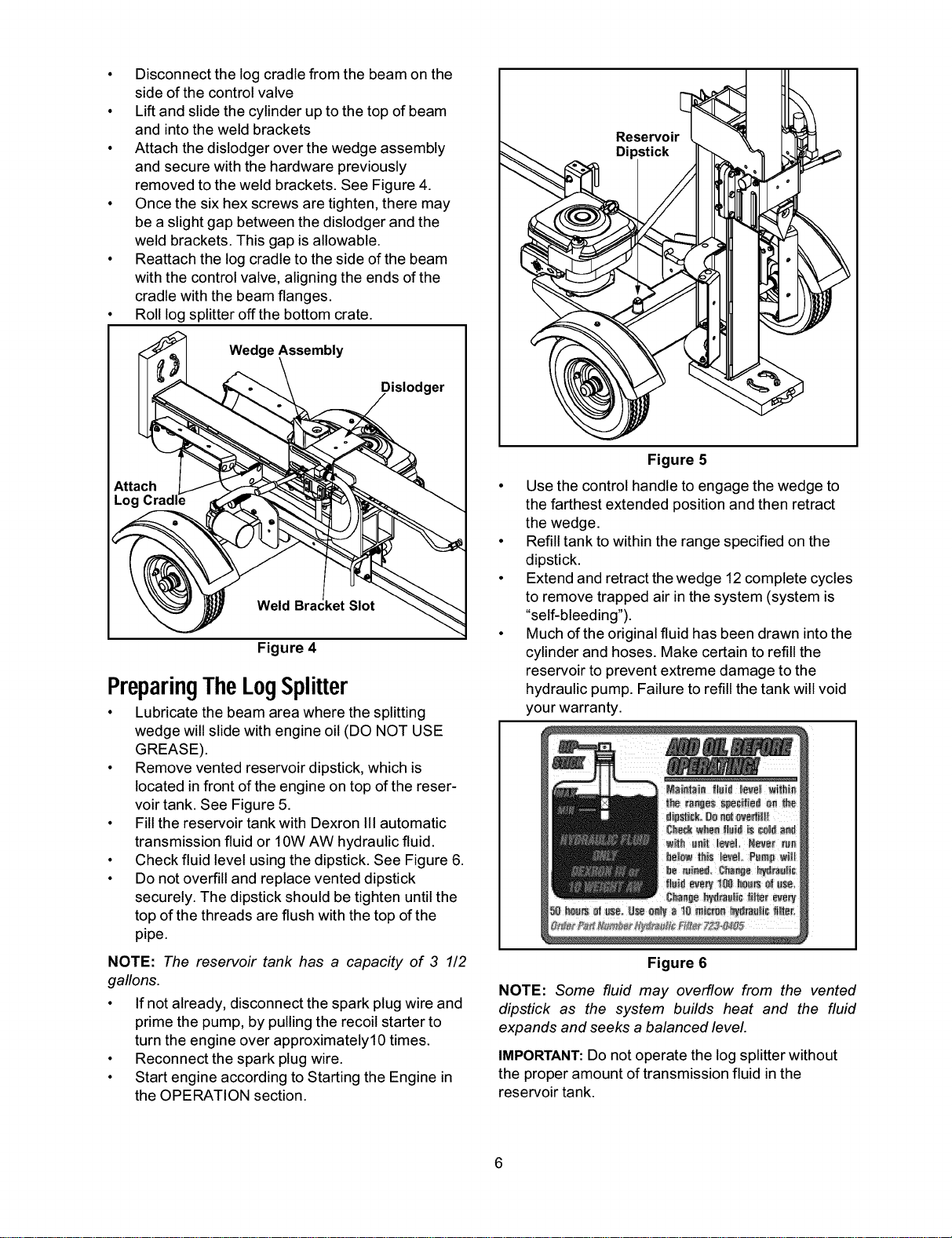
AttachingTheJack Stand(SeeFigure1)
• The jack stand isshipped inthe transport
position.
• Remove the springclipand clevis pin and pivot
thejack stand tothe operating position.
• Secure the jack stand in positionwith the clevis
pin and spring clip.
Clevis
Spring_ Pin
(Operating.....Position)JackStand _ _J
Figure 1
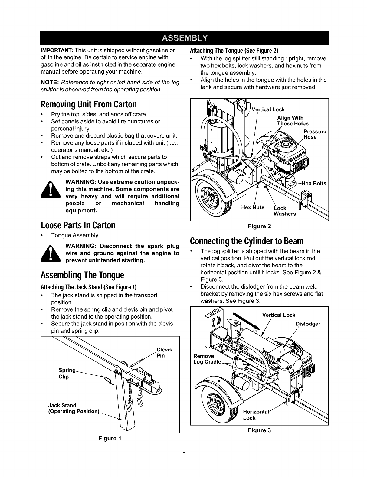
AttachingThe Tongue(SeeFigure2)
• With the log splitter still standing upright,remove
two hex bolts, lock washers, and hex nuts from
the tongue assembly.
• Align the holes in the tongue with the holes inthe
tank and secure with hardware just removed.
_ VerticalLock
r / Alhig;eWHitohes
((1"_'_'_ I /_ Pre?;ure
Figure 2
ConnectingtheCylinderto Beam
• The log splitter is shipped with the beam inthe
vertical position. Pullout the verticallock rod,
rotate itback, and pivot the beam tothe
horizontal position untilit locks.See Figure 2 &
Figure3.
• Disconnect the dislodgerfrom the beam weld
bracket by removing the six hex screws and fiat
washers. See Figure 3.
Vertical Lock
Dislodger
Remove
Log
Horizontal
Lock
Figure 3
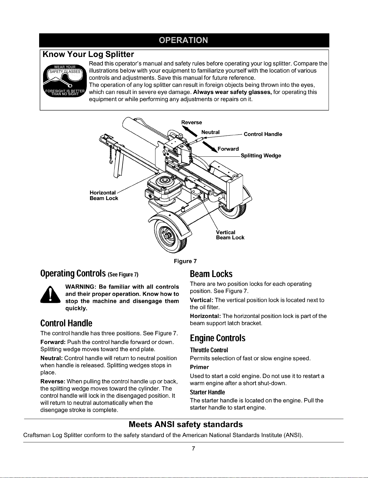
• Disconnect the log cradle from the beam on the
side of the control valve
• Lift and slide the cylinder up to the top of beam
and into the weld brackets
• Attach the dislodger over the wedge assembly
and secure with the hardware previously
removed to the weld brackets. See Figure 4.
• Once the six hex screws are tighten, there may
be a slight gap between the dislodger and the
weld brackets. This gap is allowable.
• Reattach the log cradle to the side of the beam
with the control valve, aligning the ends of the
cradle with the beam flanges.
• Roll log splitter off the bottom crate.
Wedge Assembly
Dislodger
Weld ket Slot
Figure 4
PreparingTheLogSplitter
• Lubricate the beam area where the splitting
wedge will slide with engine oil (DO NOT USE
GREASE).
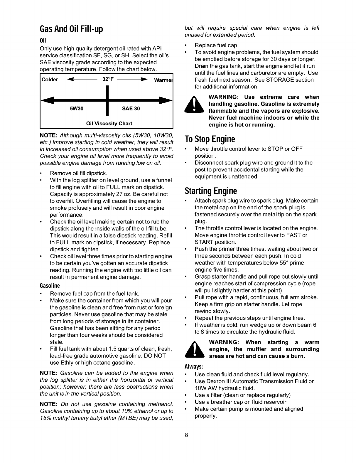
• Remove vented reservoir dipstick, which is
located in front of the engine on top of the reser-
voir tank. See Figure 5.
• Fill the reservoir tank with Dexron III automatic
transmission fluid or 10W AW hydraulic fluid.
• Check fluid level using the dipstick. See Figure 6.
• Do not overfill and replace vented dipstick
securely. The dipstick should be tighten until the
top of the threads are flush with the top of the
pipe.
NOTE: The reservoir tank has a capacity of 3 1/2
gallons.
• If not already, disconnect the spark plug wire and
prime the pump, by pulling the recoil starter to
turn the engine over approximately10 times.
• Reconnect the spark plug wire.
• Start engine according to Starting the Engine in
the OPERATION section.
Dipstick
Figure 5
• Use the control handle to engage the wedge to
the farthest extended position and then retract
the wedge.
• Refill tank to within the range specified on the
dipstick.
• Extend and retract the wedge 12 complete cycles
to remove trapped air in the system (system is
"self-bleeding").
• Much of the original fluid has been drawn into the
cylinder and hoses. Make certain to refill the
reservoir to prevent extreme damage to the
hydraulic pump. Failure to refill the tank will void
your warranty.
Figure 6
NOTE: Some fluid may overflow from the vented
dipstick as the system builds heat and the fluid
expands and seeks a balanced level
IMPORTANT:Do not operate the log splitter without
the proper amount of transmission fluid in the
reservoir tank.
Know Your Log Splitter
Read this operator's manual and safety rules before operating your log splitter. Compare the
illustrations below with your equipment to familiarize yourself with the location of various
controls and adjustments. Save this manual for future reference.
The operation of any log splitter can result in foreign objects being thrown into the eyes,
which can result in severe eye damage. Always wear safety glasses, for operating this
equipment or while performing any adjustments or repairs on it.
Reverse
Neutral
_l_Forward
Control Handle
Splitting Wedge
Horizontal
Beam Lock
Vertical
Beam Lock
Figure 7
OperatingControls(SeeFigure7)
WARNING: Be familiar with all controls
and their proper operation. Know how to
stop the machine and disengage them
quickly.
ControlHandle
The controlhandle has three positions. See Figure7.
Forward: Push the controlhandle forward or down.
Splitting wedge moves towardthe end plate.
Neutral: Control handle willreturn to neutral position
when handle isreleased. Splitting wedges stops in
place.
Reverse: When pulling the controlhandle up or back,
the splitting wedge moves towardthe cylinder.The
controlhandle will lock inthe disengaged position. It
willreturn to neutral automaticallywhen the
disengage stroke iscomplete.
BeamLocks
There are two position locks for each operating
position. See Figure 7.
Vertical: The vertical position lock is located next to
the oil filter.
Horizontal: The horizontal position lock is part of the
beam support latch bracket.
EngineControls
ThrottleControl
Permits selection offast or slow engine speed.
Primer
Used to start a coldengine. Do not use itto restart a
warm engine after a short shut-down.
Starter Handle
The starter handle is locatedon the engine. Pullthe
starter handle tostart engine.
Meets ANSI safety standards
Craftsman Log Splitter conform to the safety standard of the American National Standards Institute (ANSI).
GasAndOilFill-up
Oil
Only use high quality detergent oil rated with API
service classification SF, SG, or SH. Select the oil's
SAE viscosity grade according to the expected
operating temperature. Follow the chart below.
Colder _-" 32°F ,._ Warmel
5W30 SAE 30
y
Oil Viscosity Chart
NOTE: Although multi-viscosity oils (5W30, 10W30,
etc.) improve starting in cold weather, they will result
in increased oil consumption when used above 32°F.
Check your engine oil level more frequently to avoid
possible engine damage from running low on oil.
• Remove oil fill dipstick.
• With the log splitter on level ground, use a funnel
to fill engine with oil to FULL mark on dipstick.
Capacity is approximately 27 oz. Be careful not
to overfill. Overfilling will cause the engine to
smoke profusely and will result in poor engine
performance.
• Check the oil level making certain not to rub the
dipstick along the inside walls of the oil fill tube.
This would result in a false dipstick reading. Refill
to FULL mark on dipstick, if necessary. Replace
dipstick and tighten.
• Check oil level three times prior to starting engine
to be certain you've gotten an accurate dipstick
reading. Running the engine with too little oil can
result in permanent engine damage.
Gasoline
• Remove fuel cap from the fuel tank.
• Make sure the container from which you will pour
the gasoline is clean and free from rust or foreign
particles. Never use gasoline that may be stale
from long periods of storage in its container.
Gasoline that has been sitting for any period
longer than four weeks should be considered
stale.
• Fill fuel tank with about 1.5 quarts of clean, fresh,
lead-free grade automotive gasoline. DO NOT
use Ethly or high octane gasoline.
NOTE: Gasoline can be added to the engine when
the log splitter is in either the horizontal or vertical
position; however, there are less obstructions when
the unit is in the vertical position.
NOTE: Do not use gasoline containing methanol.
Gasoline containing up to about 10% ethanol or up to
15% methyl tertiary butyl ether (MTBE) may be used,
but will require special care when engine is left
unused for extended period.
Replace fuel cap.
To avoid engine problems, the fuel system should
be emptied before storage for 30 days or longer.
Drain the gas tank, start the engine and let it run
until the fuel lines and carburetor are empty. Use
fresh fuel next season. See STORAGE section
for additional information.
WARNING: Use extreme care when
handling gasoline. Gasoline is extremely
flammable and the vapors are explosive.
Never fuel machine indoors or while the
engine is hot or running.
ToStopEngine
• Move throttle control lever to STOP or OFF
position.
• Disconnect spark plug wire and ground itto the
post to prevent accidental starting while the
equipment is unattended.
StartingEngine
• Attach spark plug wire to spark plug. Make certain
the metal cap on the end of the spark plug is
fastened securely over the metal tip on the spark
plug.
• The throttle control lever is located on the engine.
Move engine throttle control lever to FAST or
START position.
• Push the primer three times, waiting about two or
three seconds between each push. In cold
weather with temperatures below 55° prime
engine five times.
• Grasp starter handle and pull rope out slowly until
engine reaches start of compression cycle (rope
will pull slightly harder at this point).
• Pull rope with a rapid, continuous, full arm stroke.
Keep a firm grip on starter handle. Let rope
rewind slowly.
• Repeat the previous steps until engine fires.
• If weather is cold, run wedge up or down beam 6
to 8 times to circulate the hydraulic fluid.
WARNING: When starting a warm
engine, the muffler and surrounding
areas are hot and can cause a burn.
Always:
• Use clean fluidand check fluid level regularly.
• Use Dexron III Automatic Transmission Fluidor
10W AW hydraulic fluid.
• Use a filter(clean or replace regularly)
• Use a breather cap on fluid reservoir.
• Make certain pump ismounted and aligned
properly.
• Useaflexible"spider"typecouplingbetween
engineandpumpdriveshafts.
• Keephosesclearandunblocked.
• Bleedairoutofhosesbeforeoperating.
• Flushandcleanhydraulicsystembeforestarting
afteranymalfunctionorservicing.
• Use"pipedope"onallhydraulicfittings.
• Allowtimeforwarm-upbeforesplittingwood.
• Primethepumpbeforeinitialstart-upbyturning
overtheenginewithsparkplugdisconnected.
• Splitwoodwiththegrain(lengthwise)only.
Never:
• Use when fluidis below20 ° F or above 150° F.
• Use a solid engine/pump coupling.
• Operate through relief valve for more than
several seconds.
• Attempt to adjust unloading or relief valve
settings without pressure gauges.
• Operate with air in hydraulic system.
• Use teflon tape on hydraulic fittings.
• Attempt to cut wood across the grain.
UsingTheLogSplitter
• Place the log splitter on level, dry, and solid
ground.
• Place the beam in either the horizontal or vertical
position and lock in place with the appropriate
locking rod.
• Block the front and back of both wheels.
• Place the log against the end plate and only split
wood in the direction of the grain.
• When necessary to stabilize the log, place your
hand only on sides of log. NEVER place hand on
the end between the log and splitting wedge.
• Only one adult should stabilize the log and
operate the control handle, so the operator has
full control over stabilizing the log and movement
of the splitting wedge.
Control HandlePositions
• Move control handle FORWARD or DOWN to
split wood.
• Release the control handle to stop the wedge
movement.
• Move control handle BACK or UP to return the
wedge.
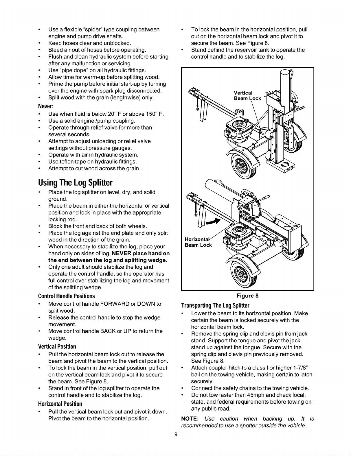
VerticalPosition
• Pullthe horizontal beam lockout to release the
beam and pivot the beam to the verticalposition.
• To lock the beam inthe verticalposition, pull out
on the vertical beam lockand pivotitto secure
the beam. See Figure 8.
• Stand in front ofthe logsplitterto operate the
controlhandle and to stabilizethe log.
HorizontalPosition
• Pullthe verticalbeam lock out and pivot itdown.
Pivotthe beam tothe horizontal position.
• To lock the beam in the horizontal position, pull
out on the horizontal beam lock and pivot itto
secure the beam. See Figure 8.
• Stand behind the reservoir tank to operate the
control handle and to stabilize the log.
Beam Lock
Figure 8
TransportingThe Log Splitter
• Lower the beam to its horizontal position. Make
certain the beam is locked securely with the
horizontal beam lock.
• Remove the spring clip and clevis pin from jack
stand. Support the tongue and pivot the jack
stand up against the tongue. Secure with the
spring clip and clevis pin previously removed.
See Figure 8.
• Attach coupler hitch to a class I or higher 1-7/8"
ball on the towing vehicle, making certain to latch
securely.
• Connect the safety chains to the towing vehicle.
• Do not tow faster than 45mph and check local,
state, and federal requirements before towing on
any public road.
NOTE: Use caution when backing up. It is
recommended to use a spotter outside the vehicle.
MAINTENANCE _ _
I,-
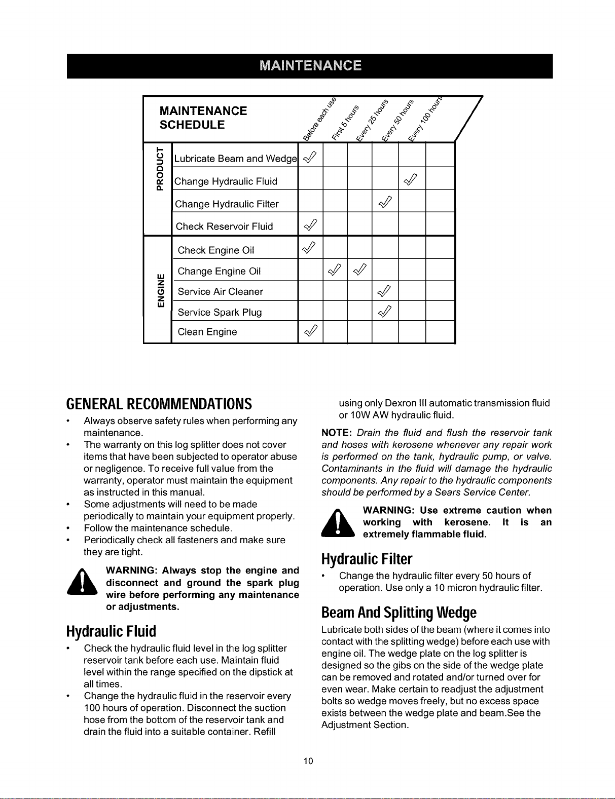
o Lubricate Beam and Wedge <_
0 Change Hydraulic Fluid
n
Change Hydraulic Filter
Check Reservoir Fluid <_
Check Engine Oil
,,, Change Engine Oil <_
Z
Service Air Cleaner
Z
I&l
Service Spark Plug
Clean Engine
GENERALRECOMMENDATIONS
• Always observe safety rules when performing any
maintenance.
• The warranty on this log splitter does not cover
items that have been subjected to operator abuse
or negligence. To receive full value from the
warranty, operator must maintain the equipment
as instructed in this manual.
• Some adjustments will need to be made
periodically to maintain your equipment properly.
• Follow the maintenance schedule.
• Periodically check all fasteners and make sure
they are tight.
WARNING: Always stop the engine and
disconnect and ground the spark plug
wire before performing any maintenance
or adjustments.
HydraulicFluid
• Check the hydraulic fluid level in the log splitter
reservoir tank before each use. Maintain fluid
level within the range specified on the dipstick at
all times.
• Change the hydraulic fluid in the reservoir every
100 hours of operation. Disconnect the suction
hose from the bottom of the reservoir tank and
drain the fluid into a suitable container. Refill
using only Dexron IIIautomatic transmission fluid
or 10W AW hydraulic fluid.
NOTE: Drain the fluid and flush the reservoir tank
and hoses with kerosene whenever any repair work
is performed on the tank, hydraulic pump, or valve.
Contaminants in the fluid will damage the hydraulic
components. Any repair to the hydraulic components
should be performed by a Sears Service Center.
WARNING: Use extreme caution when
working with kerosene. It is an
extremely flammable fluid.
HydraulicFilter
• Change the hydraulic filter every 50 hours of
operation. Use only a 10 micron hydraulic filter.
BeamAndSplittingWedge
Lubricate both sides of the beam (where it comes into
contact with the splitting wedge) before each use with
engine oil. The wedge plate on the log splitter is
designed so the gibs on the side of the wedge plate
can be removed and rotated and/or turned over for
even wear. Make certain to readjust the adjustment
bolts so wedge moves freely, but no excess space
exists between the wedge plate and beam.See the
Adjustment Section.
10
EngineMaintenance
CheckEngine0il
• Remove oilfilldipstick.
• Check oillevel on dipstick. Level should be at
FULL mark.
• Replace dipstickand tighten.
ChangingEngine0il
• Only use high qualitydetergent oilrated withAPI
service classificationSF, SG, or SH. Select the
oil's SAE viscositygrade according tothe
expected operating temperature. Refer to
operation sectionfor viscositychart.
• Stop engine and wait several minutes before
checking oil level. Withengine on level ground,
the oil mustbe to FULL mark on dipstick.
• Change engine oilafter thefirst five hoursof
operation, and every 50 hoursthereafter. Change
oilevery 25 hours ofoperation ifthe engine is
operated under heavy load or in high ambient
temperatures.
To Drain0il
Drain oilwhile engine iswarm. Followthe instructions
given below.
• Remove oil drain plug and fill dipstick.Catch oil in
a suitable container.
• When engine is drained of all oil, replace drain
plug securely.
• Refill with fresh oil, using the recommended
grade.
• Replace dipstick.
ServiceAirCleaner
The air cleaner prevents damaging dirt, dust,etc.,
from enteringthe carburetor and being forced intothe
engine and isimportanttoengine life and
performance. The air cleaner consistsof a paper pre-
cleaner and a foam filtercartridge.
WARNING: Never run the engine without
an air cleaner completely assembled.
Replace paper pre-cleaner once a year or every
100 operating hours. Replace more frequently if
operating under dusty conditions. Replacement
filters are available at any Sears Service Center.
NOTE: Do not attempt to clean or oil the paper pre-
cleaner element.
• Service cartridge every 3 months or every 25
operating hours. Service cartridge more often
under dusty conditions.
To ServiceFoamCartridge
• Loosen air cleaner cover screws, but do not
remove screw from cover. Swing cover down to
remove from hinge.
• Inspect filter for discoloration or dirt
accumulation. If either is present, proceed as
follows:
• Clean inside of body and cover thoroughly.
• Remove foam cartridge and wash in liquid
detergent and water. Squeeze dry in a clean
cloth and saturate in engine oil. Squeeze (don't
twist) in a clean absorbent cloth to remove all
excess oil.
• Reassemble foam cartridge and paper pre-
cleaner in the body. Swing cover down and
tighten the two screws loosened earlier.
WARNING: Temperature of muffler and
nearby areas may exceed 150° F(65°C).
Avoid these areas.
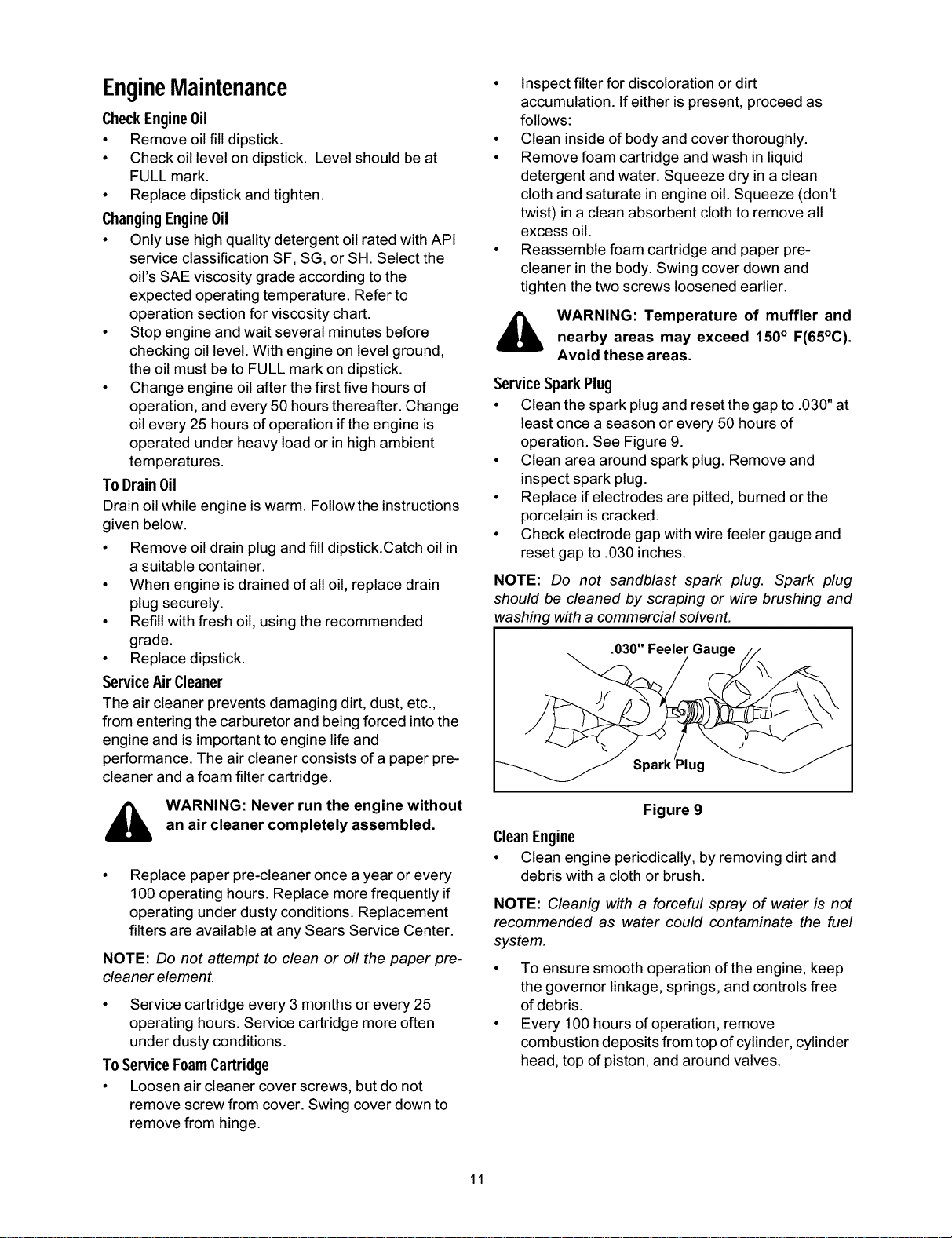
ServiceSparkPlug
• Clean the spark plug and reset the gap to .030" at
least once a season or every 50 hoursof
operation. See Figure9.
• Clean area aroundspark plug. Remove and
inspectspark plug.
• Replace ifelectrodes are pitted, burned or the
porcelain iscracked.
• Check electrode gap with wire feeler gauge and
reset gap to .030 inches.
NOTE: Do not sandblast spark plug. Spark plug
should be cleaned by scraping or wire brushing and
washing with a commercial solvent.
.030" Feeler Gau
Figure 9
CleanEngine
• Clean engine periodically, by removing dirt and
debris with a cloth or brush.
NOTE: Cleanig with a forceful spray of water is not
recommended as water could contaminate the fuel
system.
• To ensure smooth operation of the engine, keep
the governor linkage, springs, and controls free
of debris.
• Every 100 hours of operation, remove
combustion deposits from top of cylinder, cylinder
head, top of piston, and around valves.
11
WARNING: Do not at any time make any
adjustments without first stopping
engine, disconnecting spark plug wire,
and grounding it against the engine.
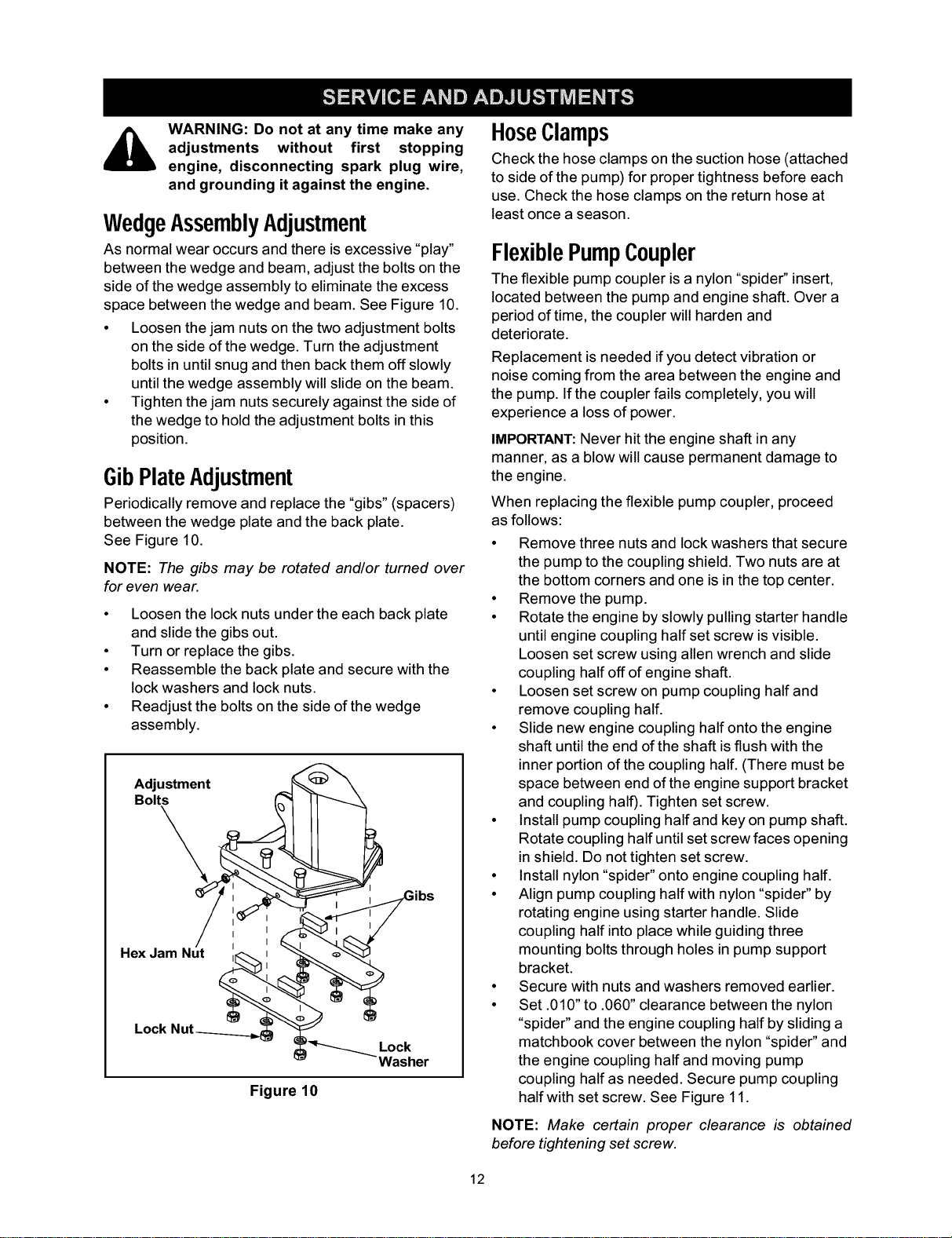
WedgeAssemblyAdJustment
As normal wear occurs and there is excessive "play"
between the wedge and beam, adjust the bolts on the
side of the wedge assembly to eliminate the excess
space between the wedge and beam. See Figure 10.
• Loosen the jam nuts on the two adjustment bolts
on the side of the wedge. Turn the adjustment
bolts in until snug and then back them off slowly
until the wedge assembly will slide on the beam.
• Tighten the jam nuts securely against the side of
the wedge to hold the adjustment bolts in this
position.
GibPlateAdjustment
Periodically remove and replace the "gibs" (spacers)
between the wedge plate and the back plate.
See Figure 10.
NOTE: The gibs may be rotated and/or turned over
for even wear.
• Loosen the lock nuts under the each back plate
and slide the gibs out.
• Turn or replace the gibs.
• Reassemble the back plate and secure with the
lock washers and lock nuts.
• Readjust the bolts on the side of the wedge
assembly.
;dlt:tment
HexJam Nut ,_ "_'_
Lock Nut__.__._.___ "_
_ _"_ _vOCker
Figure 10
HoseClamps
Check the hose clamps onthe suction hose (attached
to side ofthe pump) for propertightness before each
use. Check the hose clamps on the return hose at
least once a season.
FlexiblePumpCoupler
The flexible pump coupler is a nylon "spide¢' insert,
located between the pump and engine shaft. Over a
period of time, the coupler will harden and
deteriorate.
Replacement is needed if you detect vibration or
noise coming from the area between the engine and
the pump. If the coupler fails completely, you will
experience a loss of power.
IMPORTANT:Never hit the engine shaft in any
manner, as a blow will cause permanent damage to
the engine.
When replacing the flexible pump coupler, proceed
as follows:
• Remove three nuts and lock washers that secure
the pump to the coupling shield. Two nuts are at
the bottom corners and one is in the top center.
• Remove the pump.
• Rotate the engine by slowly pulling starter handle
until engine coupling half set screw is visible.
Loosen set screw using allen wrench and slide
coupling half off of engine shaft.
• Loosen set screw on pump coupling half and
remove coupling half.
• Slide new engine coupling half onto the engine
shaft until the end of the shaft is flush with the
inner portion of the coupling half. (There must be
space between end of the engine support bracket
and coupling halo. Tighten set screw.
• Install pump coupling half and key on pump shaft.
Rotate coupling half until set screw faces opening
in shield. Do not tighten set screw.
• Install nylon "spider" onto engine coupling half.
• Align pump coupling half with nylon "spider" by
rotating engine using starter handle. Slide
coupling half into place while guiding three
mounting bolts through holes in pump support
bracket.
• Secure with nuts and washers removed earlier.
• Set .010" to .060" clearance between the nylon
"spider" and the engine coupling half by sliding a
matchbook cover between the nylon "spider" and
the engine coupling half and moving pump
coupling half as needed. Secure pump coupling
half with set screw. See Figure 11.
NOTE: Make certain proper clearance is obtained
before tightening set screw.
12
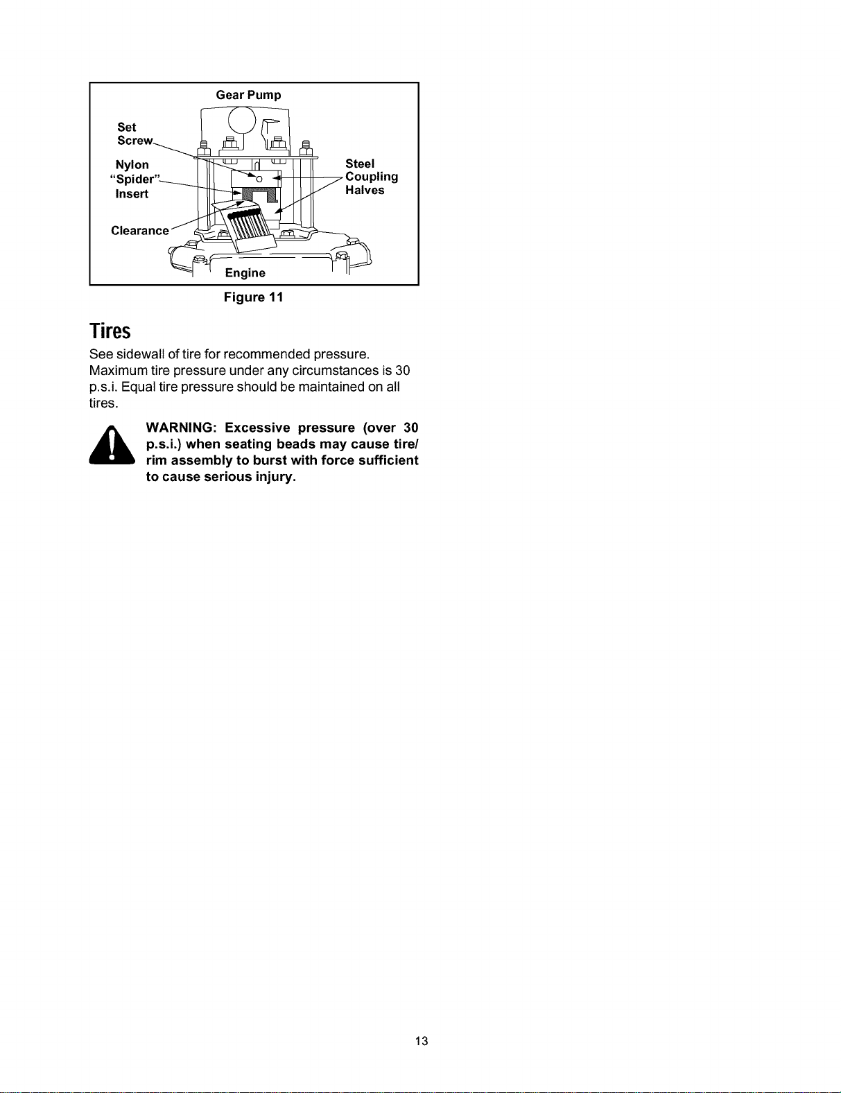
Set
Screw_
Nylon
"Spider"-___
Insert
Clearance /
@a_= Engin e
GearPump
ng
Figure 11
Tires
See sidewall of tire for recommended pressure.
Maximum tire pressure under any circumstances is 30
p.s.i. Equal tire pressure should be maintained on all
tires.
WARNING: Excessive pressure (over 30
p.s.i.) when seating beads may cause tire/
rim assembly to burst with force sufficient
to cause serious injury.
13
Prepare your log splitter for storage at the end of the
season or if the log splitter will not be used for 30 days
or more.
WARNING: Never store machine with fuel
in the fuel tank inside of building where
fumes may reach an open flame or spark
or where ignition sources are present
such as hot water and space heaters,
furnaces, clothes dyers, stoves, electric
motors, etc.
NOTE: Yearly check-up by your local Sears service
center is a good way to ensure your log spfitter will
provide maximum performance next season.
LogSplitter
• Clean the log splitter thoroughly.
• Wipe unit with an oiled rag to prevent rust,
especially on the wedge and the beam.
Engine
IMPORTANT:It is important to prevent gum deposits
from forming in essential fuel system parts such as
carburetor, fuel filter, fuel hose, or tank during
storage. Also, alcohol blended fuels (called gasohol or
using ethanol or methanol) can attract moisture which
leads to separation and formation of acids during
storage. Acidic gas can damage the fuel system of an
engine while in storage.
• Drain the fuel tank. Always drain fuel into
approved container outdoors away from open
flame. Be sure the engine is cool. Do not smoke
while handling the fuel.
• Start the engine and let it run until the fuel lines
and carburetor are empty.
• Never use engine or carburetor cleaner products
in the fuel tank or permanent damage may
occur. Use fresh fuel next season.
• Remove spark plug, pour approximately 1/2 oz.
of engine oil into cylinder and crank slowly to
distribute oil.
• Replace spark plug.
NOTE: Fuel stabilizer is an acceptable alternative in
minimizing for formation of fuel gum deposits during
storage.
Please follow the instructions below for storing your
log splitter with fuel and stabilizer in the engine.
• Add stabilizer to gasoline in fuel tank or storage
container.
• Always follow the mix ratio found on stabilizer
container.
• Run engine at least 10 minutes after adding
stabilizer to allow the stabilizer to reach the
carburetor.
• Do not drain the gas tank and carburetor if using
fuel stabilizer. Drain all the oil from the
crankcase (this should be done after the engine
has been operated and is still warm) and refill the
crankcase with fresh oil.
Other
• Do not store gasoline from one season to
another.
• Replace your gasoline can if it starts to rust.
• Store unit in a clean, dry area. Do not store next
to corrosive materials, such as fertilizer.
• Wipe equipment with an oiled rag to prevent rust.
14

Problem Possible Cause Corrective Action
Cylinder rod will not move
1. Broken drive shaft.
2. Shipping plugs left in hydraulic
hoses.
3. Set screws in coupling not adjusted
properly.
4. Loose shaft coupling.
5. Gear sections damaged.
6. Damaged relief valve.
7. Hydraulic lines blocked.
8. Incorrect oil level.
9. Damaged or blocked directional
valve.
1. Gear sections damaged.
2. Excessive pump inlet vacuum.
Cylinder shaft speed slow while
extending and retracting
Engine runs but wood will not split, or
splits too slowly
Engine stalls during splitting wood
Engine will not turn or stalls under low
load
Leaking pump shaft seal
3. Slow engine speed.
4. Damaged relief valve.
5. Incorrect oil level.
6. Contaminated oil.
7. Directional valve leaking internally.
8. Internally damaged cylinder.
1. Small gear section damaged.
2. Pump check valve leaking.
3. Excessive vacuum in pump inlet.
4. Incorrect oil level.
5. Contaminated oil.
6. Directional valve leaking internally.
7. Internally damaged cylinder.
8. Overloaded cylinder.
1. Low horsepower/weak engine.
2. Overloaded cylinder
1. Engine/pump misaligned.
2. Frozen or seized pump.
3. Weak engine.
4. Hydraulic lines blocked.
5. Blocked directional valve.
1. Broken drive shaft.
2. Engine/pump misaligned.
3. Gear sections damaged.
4. Poorly positioned shaft seal.
5. Oil breather plugged.
1. Return unit to Sears service center.
2. Disconnect hydraulic hose, remove
shipping plugs, and reconnect hose.
3. Refer to adjustment section of this
manual and adjust the couplers
4. Correct engine/pump alignment.
5. Return unit to Sears service center.
6. Return unit to Sears service center.
7. Flush and clean hydraulic system.
8. Check oil level. Refill if necessary.
9. Return unit to Sears service center
1. Return unit to Sears service center.
2. Make certain that the pump inlet
hoses are clear and unblocked. Use
short, large diameter inlet hoses.
3. Return unit to Sears service center.
4. Return unit to Sears service center.
5. Check oil level. Refill if necessary.
6. Drain oil, clean reservoir, and refill.
7. Return unit to Sears service center.
8. Return unit to Sears service center.
1. Return unit to Sears service center.
2. Return unit to Sears service center.
3. Make certain that the pump inlet
hoses are clear and unblocked. Use
short, large diameter inlet hoses.
4. Check oil level. Refill if necessary.
5. Drain oil, clean reservoir, refill, make
certain oil return tube is below oil
level.
6. Return unit to Sears service center.
7. Return unit to Sears service center.
8. Do not attempt to split wood against
the grain.
1. Return unit to Sears service center.
2. Do not attempt to split wood against
the grain. If engine stalls repeatedly,
contact Sears service center.
1. Correct alignment.
2. Return unit to Sears service center.
3. Return unit to Sears service center.
4. Flush and clean hydraulic system.
5. Return unit to Sears service center
1. Return unit to Sears service center.
2. Correct alignment.
3. Return unit to Sears service center.
4. Return unit to Sears service center.
5. Make certain reservoir is properly
vented.
15

Trouble-ShootingGuide
Problem Possible Causes
Engine fails to start 1. Dirty air cleaner.
Engine runs erratic.
Engine overheats
2. Fuel tank empty, or stale fuel.
3. Choke not in ON position.
4. Blocked fuel line.
5. Spark plug wire disconnected.
6. Faulty spark plug.
1.
2.
3.
4.
Unit running on choke.
Spark plug wire loose.
Blocked fuel line or stale fuel.
Dirty air cleaner.
5. Carburetor out of adjustment
1. Engine oil level low.
2. Dirty air cleaner.
3. Carburetor out of adjustment.
4. Air flow restricted.
Corrective Action
1. Service air cleaner following
instructions in the maintenance
section.
2. Fill tank with fresh fuel.
3. Move choke to ON.
4. Clean fuel line.
5. Connect spark plug wire to spark
plug.
6. Service spark plug following
instructions in the maintenance
section.
1. Move choke lever to OFF position.
2. Connect and tighten spark plug
wire.
3. Clean fuel line. Fill tank with fresh
fuel.
4. Service air cleaner following
instructions in the maintenance
section.
5. Contact Sears service center.
1. Fill crankcase with proper oil.
2. Service air cleaner following
instructions in the maintenance
section.
3. Contact Sears service center.
4. Stop engine, disconnect spark plug
wire, move blower housing, and
clean.
1. Refill with Dexron III automatic
transmission fluid.
Will not split logs 1. Reservoir fluid level low.
Leaking cylinder 1. Broken seals. 1. Return unit to Sears service center.
2. Scored cylinder 2. Return unit to Sears service center.
NOTE: For repairs beyond the minor adjustments fisted above, please contact your local Sears Service Center.
16

17
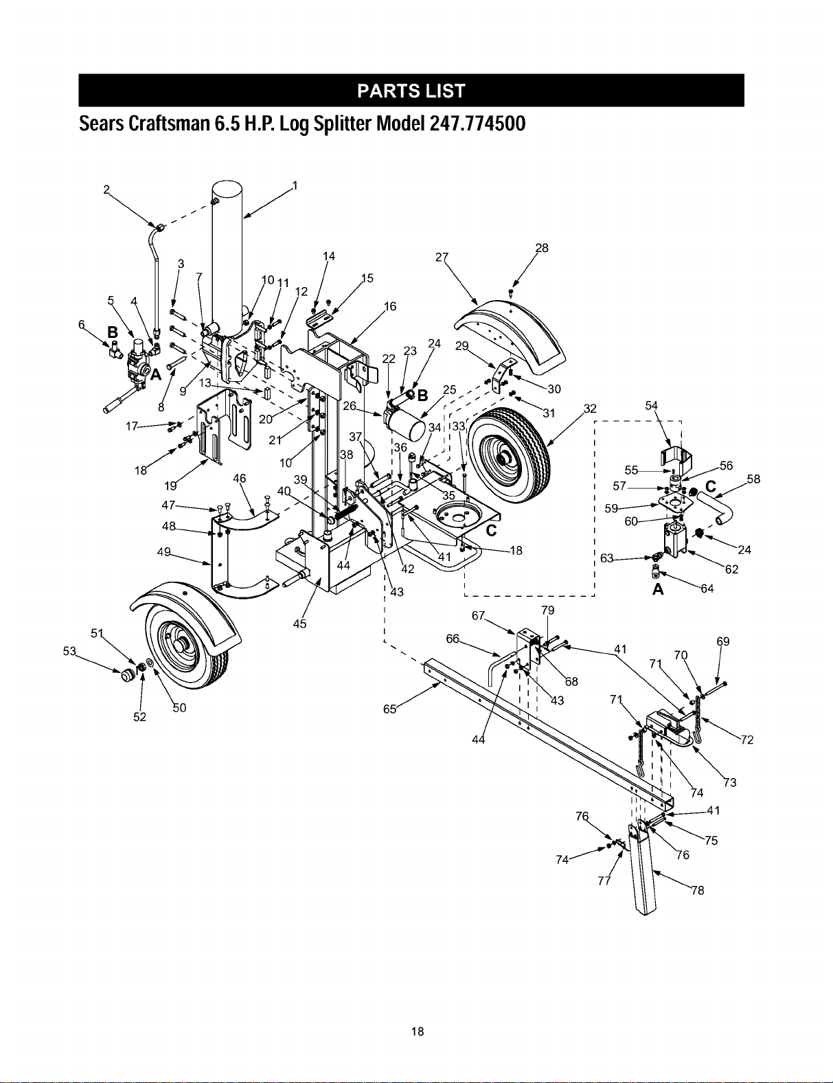
SearsCraftsman6.5 H.P.LogSplitterModel247.774500
\
45
14
[
I
I
I
28
/
C
69
41 70
52
74
I
77
18

SearsCraftsman6.5 H.P.Log SplitterModel247.774500
Ref.
PaN No.
No.
1. 718-0769
2. 727-0634
3. 710-1018
4. 737-0192
5. 718-0481
6. 737-0153
7. 737-0238
8. 710-0515
9. 719-0550
10. 712-0239
11. 712-0711
12. 710-0459A
13. 781-0351
14. 710-0604A
15. 781-1054
16. 681-0162
17. 736-0300
18. 710-0654A
19. 781-1048
20. 781-0790
21. 736-0921
22. 737-0312
23. 727-0443
24. 726-0132
25. 723-0405
26. 737-0316
27. 731-2499
28. 710-1238
29. 781-1024
30. 712-3010
31. 736-0119
32. 634-0186
33. 710-1338
34. 710-0376
35. 737-0348
36. 781-0690
37. 711-1587
38. 714-0470
39. 732-0583
Ref.
Part Description No. Part No.
Hydraulic Cylinder 40. 726-0214
Hydrauhc Tube 41. 710-0521
Hex Cap Screw 1/2-20 x 2.75 42. 736-0116
90 Degree Solid Adapter 43. 736-0169
Control Valve 44. 712-0798
Return Elbow 45. 681-0161
N_pplePipe 1/2-14 46. 781-0686
Hex Cap Screw 1/2-20 x 3.50 47. 710-3097
Wedge Assembly 48. 712-0431
Lock Nut 1/2-20 49. 781-0682
Hex Jam Nut 3/8-24 50. 736-0351
Hex Cap Screw 3/8-24 x 1.5 51. 714-0162
Adjustable Gib 52. 712-0359
Hex Washer Screw 5/16-18 x .625 53. 734-0873
Support Bracket 54. 719-0353
Beam Assembly 55. 714-0122
Flat Washer .406 ID x .875 OD 56. 718-0686
Hex Washer Screw 3/8-16 x 1.0 57. 712-0123
Dislodger 58. 727-0633
Back Plate 59. 781-0097
Lock Washer 1/2 60. 736-0119
Adapter 3/4-14 62. 718-0683
Return Hose 3/4" ID x 44" Lg. 63. 737-0329
Hose Clamp 5/8" 64. 727-0502
Oil Filter 65. 781-0788
Filter Housing 66. 747-1261
Fender 67. 781-1045
Hex Washer Screw 5/16-18 x .875 68. 732-3127
Fender Mounting Bracket 69. 710-0944
Hex Nut 5/16-18 70. 736-0262
Lock Washer 5/16 71. 750-0497
Wheel Assembly 72. 713-0433
Hex Screw 5/16-24 x 3.25 73. 727-0311
Hex Cap Screw 5/16-18 x 1.0 74. 712-0375
Vented Dipstick 75. 711-0813
Lock Rod 76. 736-0185
Clevis Pin 77. 732-0194
Cotter Pin 78. 781-0789
Compression Spring 79. 715-0120
Part Description
Push Cap
Hex Bolt 3/8-16 x 3"
Flat Washer .635 ID x .93 OD
L-Washer 3/8"
Hex Nut 3/8-16
Frame Assembly
Log Tray Bracket
Carriage Bolt 3/8-16 x 1.0
Flanged Lock Nut 3/8-16
Log Tray
Flat Washer .760 ID x .500 OD
Cotter Pin
Slotted Nut 3/4-16
Hub Cap
Couphng Shield
Square Key 3/16" x .75
Flexible Coupling
Hex Nut 5/16-24
Hose
Rear Coupling Support Bracket
Lock Washer 5/16" ID
Gear Pump (11gpm)
45 Degree Elbow
High Pressure Hydrauhc Hose
Tube Assembly
Latch Rod
Latch
Spring Compression
Hex Cap Screw 3/8-16 x 4.25
Flat Washer .385 ID x .870 OD
Spacer .375 ID x .625 OD
Chain
Couphng Hitch
Hex Lock Nut 3/8-16
Clevis Pin
Flat Washer .375 ID x .738 OD
Spring Pin
Jack Stand
Spiral Pm
19
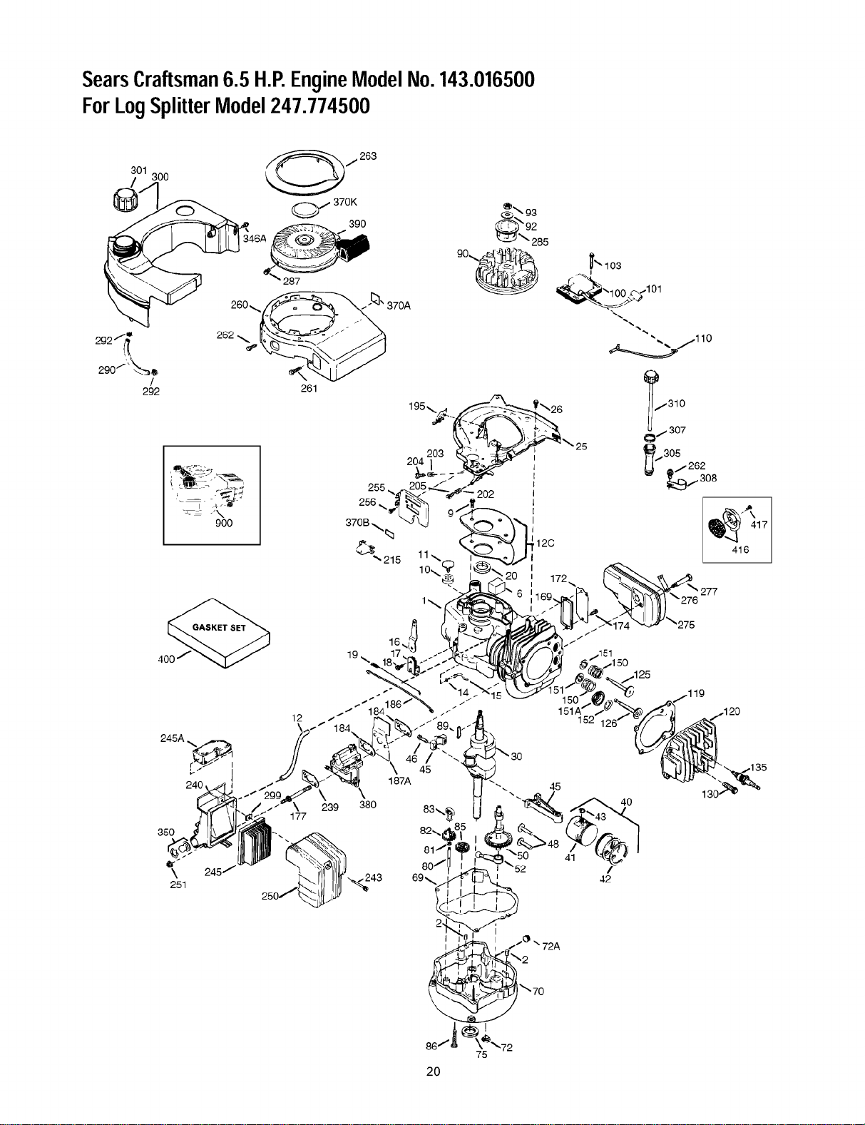
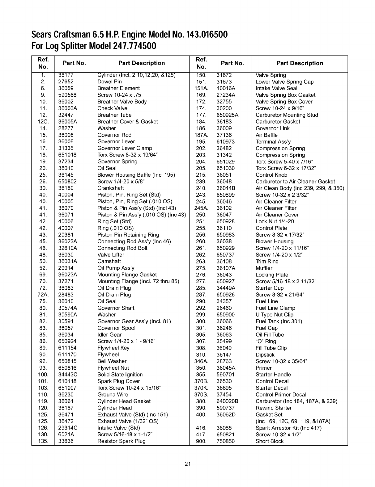
SearsCraftsman6.5 H.P,EngineModelNo.143.016500
ForLogSplitterModel247.774500
301
/ 300
292?(_
290JJ_-,_ _,
/
292
260_
262
900
245A _
240
261
390
Q_92
<-_J_ 285
_o_%
255
256
370B _
_'215
_" 1o3
'_1O0 ,,_1101
" ,.,. 110
12
152
\
380
45
187A
45
20
SearsCraftsman6.5H.P,EngineModelNo.143.016500
ForLogSplitterModel247.774500
Ref.
Part No.
No.
1. 36177
2. 27652
6. 36059
9. 590568
10. 36002
11. 36003A
12. 32447
12C. 36005A
14. 28277
15. 36006
16. 36008
17. 31335
18. 651018
19. 37234
20. 36010
25. 36145
26. 650802
30. 36180
40. 40004
40. 40005
41. 36070
41. 36071
42. 40006
42. 40007
43. 20381
45. 36023A
46. 32610A
48. 36030
50. 36031A
52. 29914
69. 36023A
70. 37271
72. 36083
72A. 28483
75. 36010
80. 30574A
81. 30590A
82. 30591
83. 36057
85. 36034
86. 650924
89. 611154
90. 611170
92. 650815
93. 650816
100. 34443C
101. 610118
103. 651007
110. 36230
119. 36061
120. 36187
125. 36471
125. 36472
126. 29314C
130. 6021A
135. 33636
Ref.
Part Description No. Part No.
Cylinder (Incl. 2,10,12,20, &125) 150. 31672
Dowel Pin 151. 31673
Breather Element 151A. 40016A
Screw 10-24 x .75 169. 27234A
Breather Valve Body 172. 32755
Check Valve 174. 30200
Breather Tube 177. 650925A
Breather Cover & Gasket 184. 36183
Washer 186. 36009
Governor Rod 187A. 37136
Governor Lever 195. 610973
Governor Lever Clamp 202. 36482
Torx Screw 8-32 x 19/64" 203. 31342
Governor Spring 204. 651029
Oil Seal 205. 651030
Blower Housing Baffle (Incl 195) 215. 36051
Screw 1/4-20 x 5/8" 239. 36048
Crankshaft 240. 36044B
Piston, Pin, Ring Set (Std) 243. 650899
Piston, Pm, Ring Set (.010 OS) 245. 36046
Piston& Pin Ass'y (Std) (Inc143) 245A. 36102
Piston& Pin Ass'y (.010 OS) (Inc 43) 250. 36047
R=ngSet (Std) 251. 650928
Ring (.010 OS) 255. 36110
Piston Pin Retaining Ring 256. 650983
Connecting Rod Ass'y (Inc 46) 260. 36038
Connecting Rod Bolt 261. 650929
Valve Lifter 262. 650737
Camshaft 263. 36108
Oil Pump Ass'y 275. 36107A
Mounting Flange Gasket 276. 36043
Mounting Flange (Incl. 72 thru 85) 277. 650927
Oil Drain Plug 285. 34449A
Oil Drain Plug 287. 650926
Oil Seal 290. 34357
Governor Shaft 292. 26460
Washer 299. 650900
Governor Gear Ass'y (Incl. 81) 300. 36066
Part Description
Valve Spring
Lower Valve Spring Cap
Intake Valve Seal
Valve Spring Box Gasket
Valve Spring Box Cover
Screw 10-24 x 9/16"
Carburetor Mounting Stud
Carburetor Gasket
Governor Link
Air Baffle
Terminal Ass'y
Compression Spring
Compression Spring
Torx Screw 5-40 x 7/16"
Torx Screw 6-32 x 17/32"
Control Knob
Carburetor to Air Cleaner Gasket
Air Clean Body (Inc 239,299, & 350)
Screw 10-32 x 2 3/32"
Air Cleaner Filter
Air Cleaner Filter
Air Cleaner Cover
Lock Nut 1/4-20
Control Plate
Screw 8-32 x 17/32"
Blower Hous=ng
Screw 1/4-20 x 11/16"
Screw 1/4-20 x 1/2"
Trim Ring
Muffler
Locking Plate
Screw 5/16-18 x 2 11/32"
Starter Cup
Screw 8-32 x 21/64"
Fuel Line
Fuel Line Clamp
U Type Nut Clip
Fuel Tank (Inc 301)
Governor Spool 301. 36246
Idler Gear 305. 36063
Screw 1/4-20 x 1 - 9/16" 307. 35499
Flywheel Key 308. 36040
Flywheel 310. 36147
Bell Washer 346A. 28763
Flywheel Nut 350. 36045A
Solid State Ignition 355. 590701
Spark Plug Cover 370B. 36530
Torx Screw 10-24 x 15/16" 370K. 36695
Ground Wire 370S. 37454
Cylinder Head Gasket 380. 640020B
Cylinder Head 390. 590737
Exhaust Valve (Std) (Inc 151) 400. 36062D
Exhaust Valve (1/32" OS)
Intake Valve (Std) 416. 36085
Screw 5/16-18 x 1-1/2" 417. 650821
Resistor Spark Plug 900. 750850
Fuel Cap
Oil Fill Tube
"O" Ring
Fill Tube Clip
Dipstick
Screw 10-32 x 35/64"
Primer
Starter Handle
Control Decal
Starter Decal
Control Primer Decal
Carburetor (Inc 184, 187A, & 239)
Rewind Starter
Gasket Set
(Inc 169, 12C, 69, 119, &187A)
Spark Arrestor Kit (Inc 417)
Screw 10-32 x 1/2"
Short Block
21
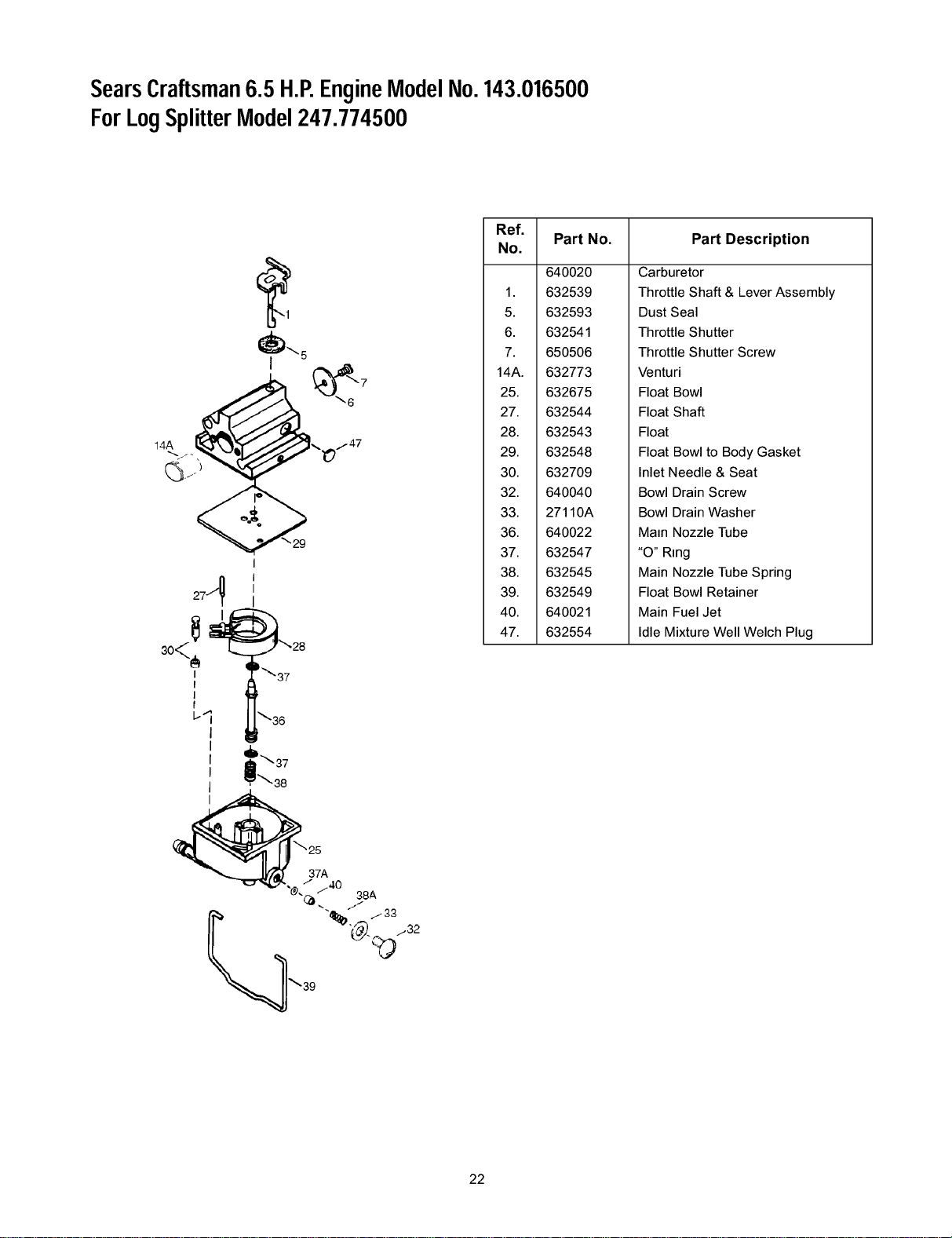
SearsCraftsman6.5 H.P,EngineModelNo.143.016500
ForLogSplitterModel247.774500
_5
1 .__.,_/47
V"29
274
I
I
I
f
L-'i
I
_'_-28
_37
_36
i ,6
i l
, _'38
_'_25
_'_:_ 37A
"._ / ,/40
-(_ ,. 38A
"%/._;3
"_,_. ....32
_39
Ref.
Part No. Part Description
No.
640020
1. 632539
5. 632593
6. 632541
7. 650506
14A. 632773
25. 632675
27. 632544
28. 632543
29. 632548
30. 632709
32. 640040
33. 27110A
36. 640022
37. 632547
38. 632545
39. 632549
40. 640021
47. 632554
Carburetor
Throttle Shaft & Lever Assembly
Dust Seal
Throttle Shutter
Throttle Shutter Screw
Venturi
Float Bowl
Float Shaft
Float
Float Bowl to Body Gasket
Inlet Needle & Seat
Bowl Drain Screw
Bowl Drain Washer
Main Nozzle Tube
"O" Ring
Main Nozzle Tube Spring
Float Bowl Retainer
Main Fuel Jet
Idle Mixture Well Welch Plug
22
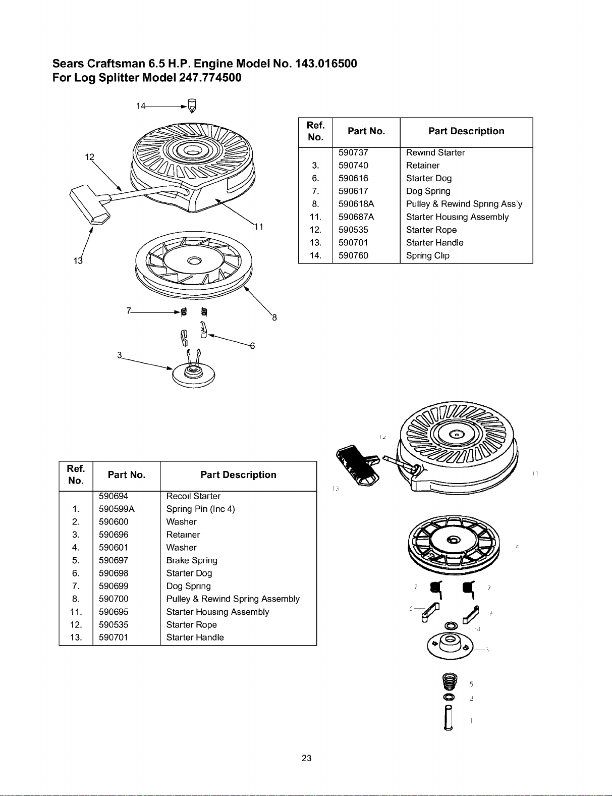
Sears Craftsman 6.5 H.P. Engine Model No. 143.016500
For Log Splitter Model 247.774500
12
Ref.
Part No. Part Description
No.
590737
3. 590740
6. 590616
7. 590617
8. 590618A
11. 590687A
12. 590535
13. 590701
14. 590760
Rewind Starter
Retainer
Starter Dog
Dog Spring
Pulley & Rewind Spring Ass'y
Starter Housing Assembly
Starter Rope
Starter Handle
Spring Chp
Ref.
Part No. Part Description
No.
590694
1. 590599A
2. 590600
3. 590696
4. 590601
5. 590697
6. 590698
7. 590699
8. 590700
11. 590695
12. 590535
13. 590701
Recod Starter
Spring Pin (Inc 4)
Washer
Retainer
Washer
Brake Spring
Starter Dog
Dog Spring
Pulley & Rewind Spring Assembly
Starter Housing Assembly
Starter Rope
Starter Handle
=;7
5
23
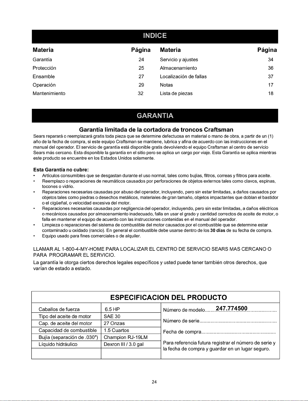
Materia Pdgina Materia Pdgina
Garantia 24 Servicio y ajustes 34
Protecci6n 25 Almacenamiento 36
Ensamble 27 Localizaci6n de fallas 37
Operaci6n 29 Notas 17
Mantenimiento 32 Lista de piezas 18
Garantia limitada de la cortadora de troncos Craftsman
Sears reparar_ o reemplazar_ gratis toda pieza que se determine defectuosa en material o mano de obra, a partir de un (1)
aSo de la fecha de compra, si este equipo Craftsman se mantiene, lubrica y afina de acuerdo con las instrucciones en el
manual del operador. El servicio de garantia est_ disponible gratis devolviendo el equipo Craftsman al centro de servicio
Sears m_s cercano. Esta disponible la garantia en el sitio pero se aplica un cargo por viaje. Esta Garantia se aplica mientras
este producto se encuentre en los Estados Unidos solamente.
Esta Garantia no cubre:
• Articulos consumibles que se desgastan durante el uso normal, tales como bujias, filtros, correas y filtros para aceite.
• Reemplazo o reparaciones de neum_ticos causados por perforaciones de objetos externos tales como clavos, espinas,
tocones o vidrio.
• Reparaciones necesarias causadas por abuso del operador, incluyendo, pero sin estar limitadas, a daSos causados por
objetos tales como piedras o desechos met_licos, materiales de gran tamaSo, objetos impactantes que doblan el bastidor
o el cig0eSal, o velocidad excesiva del motor.
• Reparaciones necesarias causadas por negligencia del operador, incluyendo, pero sin estar limitadas, a daSos el_ctricos
o mec_nicos causados por almacenamiento inadecuado, falla en usar el grado y cantidad correctos de aceite de motor, o
falla en mantener el equipo de acuerdo con las instrucciones contenidas en el manual del operador.
• Limpieza o reparaciones del sistema de combustible del motor causados por el combustible que se determine estar
contaminado u oxidado (rancio). En general el combustible debe usarse dentro de los 30 dias de su fecha de compra.
• Equipo usado para fines comerciales o de alquiler.
LLAMAR AL 1-800-4-MY-HOME PARA LOCALIZAR EL CENTRO DE SERVICIO SEARS MAS CERCANO O
PARA PROGRAMAR EL SERVICIO.
La garantia le otorga ciertos derechos legales especificos y usted puede tener tambien otros derechos, que
varian de estado a estado.
ESPECIFICACION DEL PRODUCTO
Caballos de fuerza
Tipo del aceite de motor
Cap. de aceite del motor
Capacidad de combustible
Bujia (separaci6n de .030")
Liquido hidraulico
6.5HP
SAE 30
27 Onzas
1.5 Cuartos
Champion RJ-19LM
Dexron III / 3.0 gal
NQmero de modelo .........2...4..7.:..7..7..4...5..0...0......................
NQmero de serie ........................................................
Fecha de compra ......................................................
Para referencia futura registrar el nQmero de serie y
la fecha de compra y guardar en un lugar seguro.
24
ADVERTENClA: Este simbolo indica importantes instrucciones de seguridad la cuales, si no se
observan, pueden poner en peligro la seguridad personal y/o la propiedad suya y de terceros. Lea y siga todas
las instrucciones en este manual antes de intentar operar esta m_quina. El no cumplir con estas instrucciones
puede resultar en lesiones personales. Cuando vea este simbolo obedezca a su advertencia.
ADVERTENClA: El escape del motor, algunos de sus integrantes, y ciertos componentes del
vehiculo contienen o emiten substancias quimicas conocidas al Estado de California como
causantes de cancer y defectos de nacimiento u otras lesiones reproductoras.
PELIGRO: Esta m_quina fue fabricada para operarse de acuerdo con las reglas para una operaci6n
segura. AI igual que con cualquier tipo de equipo motorizado, el descuido o error por parte del operador puede
resultar en lesiones graves. Esta m_quina es capaz de amputar manos y pies y despedir objetos. La falla en
observar las instrucciones siguientes de protecci6n puede resultar en lesiones graves o la muerte.
CAPACITACION
1. Leer, entender y seguir todas las instrucciones en la
m_quina y en el manual(es) antes de operar.
Familiarizarse completamente con los controles y el
uso apropiado de esta m_quina antes de operarla.
Guardar este manual en un lugar seguro para
referencia futura y regular y para ordenar piezas de
repuesto.
2. Familiarizarse con todos los controles y su operaci6n
correcta. Saber como parar la m_quina y
desenganchar r_pidamente los controles.
3. No permitir nunca que los niSos menores de 14 aSos
de edad operen esta m_quina. Los niSos de 14 aSos
de edad y mayores deben leer y entender las
instrucciones de operaci6n y las reglas de seguridad
de este manual y deben ser capacitados y
supervisados por uno de los padres.
4. Nunca permita que los adultos operen esta m_quina
sin la instrucci6n adecuada.
5. Muchos accidentes ocurren cuando m_s de una
persona opera la m_quina. Si hay un asistente
ayudando a cargar los troncos, no activar nunca el
control hasta que el asistente est_ a un minimo de 10
pies de la m_quina.
6. Mantener a los espectadores, ayudantes, animales
dom_sticos y niSos a 10 pies, por Io menos, de la
m_quina mientras est_ en operaci6n.
7. Nunca permitir pasajeros en m_quina.
8. Nunca transportar carga en la m_quina.
9. Las cortadoras hidr_ulicas de troncos alcanzan
presiones elevadas durante la operaci6n. El liquido
que escapa a trav_s de un orificio del tamaSo de una
cabeza de alfiler puede penetrar la piel y causar
envenenamiento de la piel, gangrena o la muerte.
Prestar atenci6n en todo momento a las instrucciones
siguientes:
a. No inspeccionar por p6rdidas con la mano.
b. No operar la m_quina con mangueras,
adaptadores o tuberias gastados, doblados,
agrietados o daSados.
c. Antes de cambiar o ajustar los adaptadores,
mangueras, tuberias u otros componentes del
sistema, parar el motor y disminuir la presi6n
del sistema hidr_ulico.
d. No ajustar las graduaciones de presi6n de la
bomba o vMvula.
10. Las p_rdidas pueden detectarse pasando un cart6n o
madera, usando guantes protectores y anteojos
protectores, sobre el _rea sospechosa. Observar la
decoloraci6n del cart6n o la madera.
11. Consultar inmediatamente con un m6dico si el
operador se ha lesionado por el liquido de p_rdida. Si
no se administra inmediatamente tratamiento m_dico
puede producirse una infecci6n o reacci6n grave.
12. Mantener la zona del operador y el _rea adyacente
libre para poder pararse con protecci6n y seguridad.
13. Si la m_quina est_ equipada con un motor de
combusti6n interna y se va a usar cerca de bosques
silvestres o tierra cubierta de matorrales y grama, el
escape del motor debe estar equipado con un supresor
de chispas. Asegurarse de cumplir con todos los
c6digos locales, estatales y federales aplicables. Se
debe tener siempre equipo adecuado extintor de
incendios.
14. Esta m_quina debe usarse para cortar madera
solamente y no se debe usar para ningt)n otro fin.
15. Seguir las instrucciones en el manual(es) provisto con
el aditamento(s) para esta m_quina.
PREPARACION
1. Usar siempre zapatos protectores o botas pesadas.
2. Usar siempre anteojos protectores o antiparras
protectoras durante la operaci6n de esta m_quina.
3. No usar nunca joyas o ropas holgadas que puedan
enredarse en las piezas m6viles o giratorias de la
m_quina.
4. Antes de operar asegurarse que la m_quina est_ en
una superficie nivelada.
5. Bloquear siempre la m_quina segQn requerido para
prevenir un movimiento inesperado, y trabar en la
posici6n horizontal o vertical.
6. Operar siempre la m_quina de la zona(s) del operador
especificada en el manual.
7. Los troncos deben cortarse con extremos cuadrados
antes de cortarlos.
8. Usar la cortadora de troncos durante el dia o bajo una
buena luz artificial.
25

9.
Para evitar lesiones personales o dafios a la propiedad
se debe ser muy precavido al manejar la gasolina. La
gasolina es extremadamente inflamable y los vapores
son explosivos.. Pueden ocurrir lesiones personales
graves cuando se derrama gasolina sobre el operador o
sus ropas ya que puede encenderse. Lavarse la piel y
cambiarse de ropas inmediatamente.
a. Usar un recipiente aprobado de gasolina
solamente.
b. Apagar todos los cigarrillos, cigarros, pipas, y
otras fuentes de combusti6n.
c. Nunca se debe cargar gasolina bajo techo.
d. Nunca extraer la tapa de gasolina o agregar
combustible mientras el motor est_ caliente o
funcionando.
e. Antes de cargar gasolina permitir que el motor se
enfrie por dos minutos por Io menos.
f. Nunca Ilenar en exceso el tanque de gasolina.
Llenar el tanque a no m_s de 1/2 pulgada por
debajo de la secci6n inferior del cuello del
Ilenador, para proveer espacio para la expansi6n
del combustible.
g. Volver a colocar la tapa del tanque de gasolina y
ajustar bien.
h. Si se derrama gasolina, limpiar con un trapo la
m_quina yel equipo y mover la m_quina a otra _rea.
Esperar 5 minutos antes antes de arrancar el motor.
i. No almacenar nunca la m_quina o el recipiente de
combustible bajo techo donde haya una llama
expuesta, chispas o llama piloto como en
calentadores de agua, calentadores de cuarto,
caldera, secadora de ropa uotros artefactos agas.
j. Antes de almacenar, permitir que la m_quina se
enfrie por 5 minutos por Io menos.
OPERACION
1. Antes de arrancar esta m_quina, repasar las"lnstrucciones
de Protecci6n". El no seguir esas reglas puede resultar en
lesiones graves al operador o a los espectadores.
2. No dejar nunca la m_quina desatendida mientras el
motor est_ funcionando.
3. No operar la m_quina mientras se est_ bajo la influencia
de alcohol, drogas o medicaci6n.
4. No permitir nunca que ninguna persona opere esta
m_quina sin una instrucci6n adecuada.
5. Operar siempre esta m_quina con todo el equipo de
seguridad en su lugar y funcionando. Asegurarse que
todos los controles est_n bien ajustados para una
operaci6n segura.
6. No cambiar las graduaciones del regulador del motor ni
operar el motor a velocidad excesiva. El regulador controla
la velocidad m_xima segura de operaci6n del motor.
7. AI cargar un tronco, colocar siempre las manos sobre los
lados del tronco, no en los extremos, y nunca usar el pie
para estabilizar un tronco. El no hacerlo puede resultar
en que los dedos, dedos del pie, mano o pie sean
aplastados o amputados.
8. Usar las manos solamente para operar los controles.
9. No intentar nunca cortar m_s de un tronco por vez, a
menos que el ariete est_ completamente extendido y se
necesite un segundo tronco para completar la
separaci6n del primer tronco.
10. Para los troncos que no se han cortado cuadrados, el
extremo menos cuadrado y la porci6n m_s larga del
tronco deben colocarse hacia la viga y curia, y el extremo
cuadrado debe colocarse hacia la placa del extremo.
11. AI cortar en la posici6n vertical, estabilizar el tronco antes
de mover el control. Cortar como sigue:
a. Colocar el tronco sobre la placa del extremo y
girarlo hasta que se apoye contra la viga yes
estable.
b. AI cortar troncos extra grandes o irregulares, el
tronco debe estabilizarse con cutlas de madera o
madera cortada entre el tronco y la placa del
extremo o el suelo.
12. Mantener siempre los dedos alejados de grietas que se
abren en el tronco al cortar. Las grietas pueden cerrarse
st)bitamente y aprisionar o amputar los dedos.
13. Mantener limpia el _rea de trabajo. Extraer
inmediatamente la madera cortada alrededor de la
m_quina de manera de no tropezar sobre la misma.
14. Nunca mover la m_quina mientras el motor est_
funcionando.
15. Esta m_quina no debe remolcarse en ninguna calle,
carretera o camino pt)blico sin verificar primero los
requerimientos existentes locales, estatales y federales
para vehiculos. Toda licencia o modificaciones tales
como luces posteriores, etc., requeridas para cumplir, es
la responsabilidad exclusiva del comprador. Consultar
con el distribuidor local si en el Estado se requiere una
"Declaraci6n de Origen".
16. Consultar la secci6n de remolque en este manual, para
las instrucciones de remolque una vez que se haya
cumplido con todos los requerimientos federales, locales
o estatales.
MANTENIMIENTOYALMACENAMIENTO
1. Parar el motor, desconectar la bujia y conectar a tierra
contra el motor antes de limpiar o inspeccionar la
m_quina.
2. Antes de cambiar o ajustar los adaptadores, mangueras,
tuberias u otros componentes del sistema, parar el motor
y disminuir la presi6n del sistema hidr_ulico.
3. Para evitar incendios, limpiar los desechos y paja de las
_reas del motor y del silenciador. Si el motor est_ equipado
con un silenciador del supresor de chispas, limpiarlo e
inspeccionarlo regularmente de acuerdo con las
instrucciones del fabricante. Reemplazarlo si est_ dafiado.
4. Inspeccionar peri6dicamente que todas las tuercas y
pernos, mordazas de las mangueras y adaptadores
hidr_ulicos est_n firmes para asegurarse que el equipo
est_ en buen estado de trabajo.
5. Inspeccionar todas las guardas y protectores de
seguridad para asegurarse que est_n en la posici6n
correcta. Nunca operar sin que las guardas protectoras,
protectores u otras caracteristicas protectoras est_n en
su lugar.
6. La v_lvula de escape de presi6n est_ pregraduada de
f_brica. No ajustar la v_lvula.
7. Nunca intentar mover esta m_quina sobre un terreno
escarpado o irregular sin un vehiculo de remolque o
ayuda adecuada.
26
IMPORTANTE:Estaunidadseenviasingasolinaoaceite
enelmotor.Antesdeoperarlam_quina,asegurarsede
cargargasolinayaceiteseg0nindicadoenelmanual
separadodelmotor.
NOTA: La referencia a la derecha o izquierda de la
cortadora de troncos se observa desde la posicidn
de operacidn.
Extracciondelaunidaddelacaja
• Separar eltope, ladosy extremosdel caj6n.
• Colocar lospanelesa un lado para evitar perforaciones
de losneum_ticoso lesionespersonales.
• Extraer y descartar labolsa pl_sticaque cubre la unidad.
• Extraer las piezassueltas si est_n incluidascon la
unidad (por ej., manual del operador,etc.)
• Cortar y extraer lascintas que aseguran las piezasal
rondo del caj6n. Extraer los pernosde laspiezas
restantesque pueden estar empernadas alrondo del
caj6n.
ADVERTENCIA: Se debe ser muy precav-
ido al desempacar esta m_quina. Algunos
componentes son muy pesados y requieren
m_s personas o equipo mec_nico de manejo.
Piezassueltasenunacaja
• Conjunto de la leng0eta.
,_ ADVERTENCIA: Desconectar el cable de la
bujia y conectar a tierra contra el motor para
prevenir un arranque inesperado.
EnsambledelalengLieta
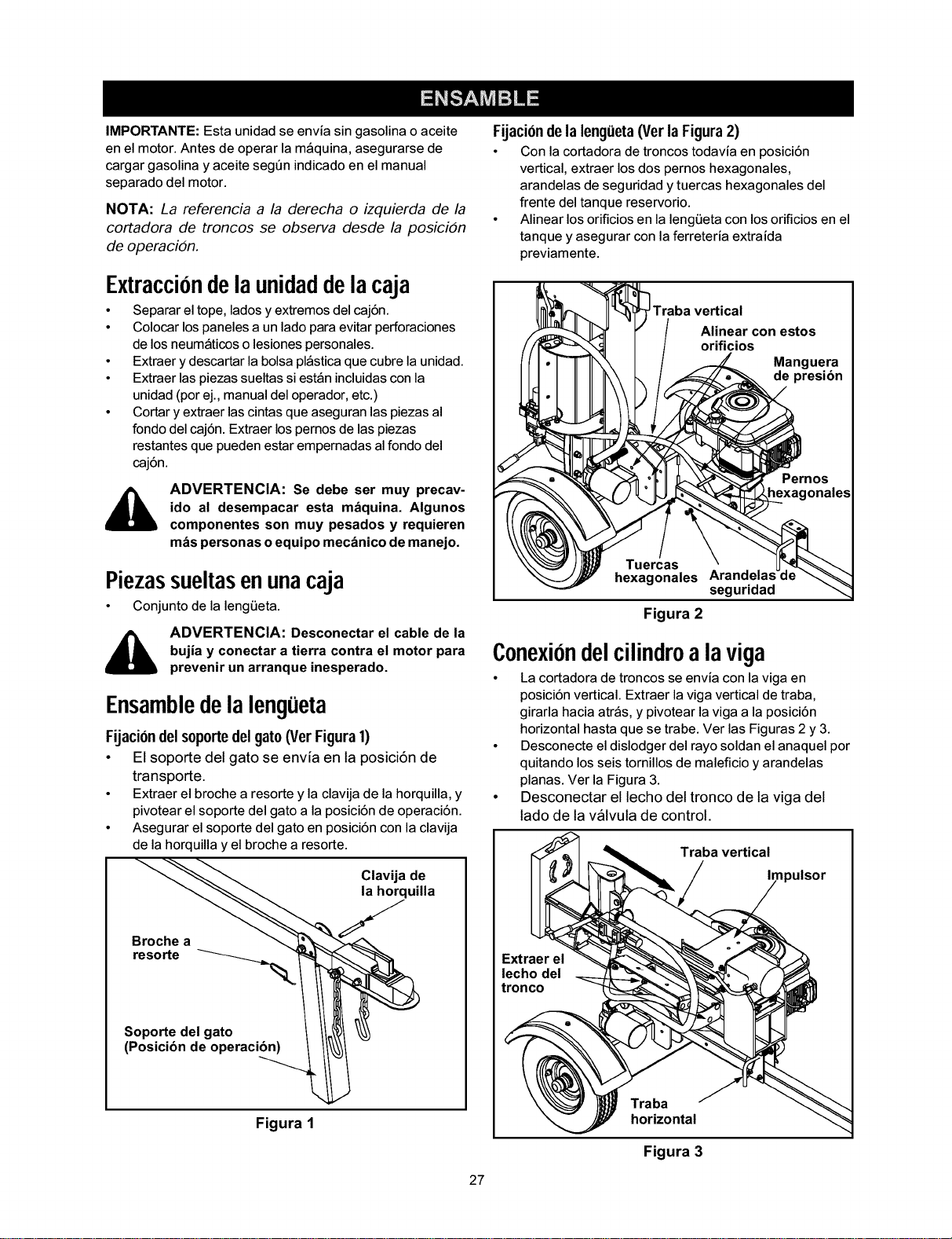
Fijaci0ndelsoportedelgato(VerFigura1)
• El soporte del gato se envia en la posici6n de
transporte.
• Extraer el broche a resorte y la clavija de la horquilla, y
pivotear el soporte del gato a la posici6n de operaci6n.
• Asegurar el soporte del gato en posici6n con la clavija
de la horquilla y el broche a resorte.
Clavija de
resorte __
(Posicibn de operaciS-°p°'rt'e"de'l gato ._
Figura 1
27
Fijaci0ndela leng(ieta(Verla Figura2)
• Con la cortadora de troncos todavia en posici6n
vertical, extraer los dos pernos hexagonales,
arandelas de seguridad y tuercas hexagonales del
frente del tanque reservorio.
• Alinear losorificiosen laleng0eta con losorificiosen el
tanque y asegurar con la ferreteria extraida
previamente.
Traba vertical
Alinear con estos
orificios
Manguera
, resibn
">_ .'IFII,[_,_"_ Pernos
segunaaa
Figura 2
Conexiondelcilindroalaviga
• La cortadora de troncos se envia con la riga en
posici6n vertical. Extraer la viga vertical de traba,
girarla hacia atr_s, y pivotear la viga a la posici6n
horizontal hasta que se trabe. Ver las Figuras 2 y 3.
• Desconecte el dislodger del rayo soldan el anaquel por
quitando los seis tomillos de maleficio y arandelas
planas. Ver la Figura 3.
• Desconectar el lecho del tronco de la viga del
lado de la valvula de control.
Traba vertical
Extraer el
lecho del
tronco
Traba
horizontal
Figura 3
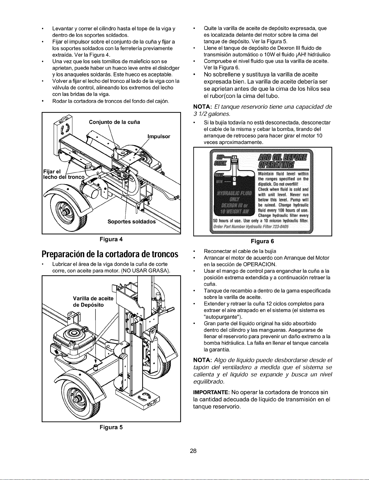
• Levantar y correr el cilindro hasta el tope de la viga y
dentro de los soportes soldados.
• Fijar el impulsor sobre el conjunto de la curia y fijar a
los soportes soldados con la ferreteria previamente
extraida. Ver la Figura 4.
• Una vez que los seis tomillos de maleficio son se
aprietan, puede haber un hueco leve entre el dislodger
y los anaqueles soldar_s. Este hueco es aceptable.
• Volver afijar el lecho del tronco al lado de la viga con la
v_lvula de control, alineando los extremos del lecho
con las bridas de la viga.
• Rodar la cortadora de troncos del fondo del caj6n.
Conjunto de la cuha
Impulsor
Soportes soldado.,
• Quite la varilla de aceite de dep6sito expresada, que
es Iocalizada delante del motor sobre la cima del
tanque de dep6sito. Ver la Figura 5.
• Llene el tanque de dep6sito de Dexron IIIfluido de
transmisi6n autom_tico o 10W el fluido iAH! hidr_ulico
• Compruebe el nivel fluido que usa la varilla de aceite.
Ver la Figura 6.
• No sobrellene y sustituya la varilla de aceite
expresada bien. La varilla de aceite deberia ser
se aprietan antes de que la cima de los hilos sea
el rubor(con la cima del tubo.
NOTA: El tanque reservorio tiene una capacidad de
3 1/2galones.
• Si la bujia todavia no est_ desconectada, desconectar
el cable de la misma y cebar la bomba, tirando del
arranque de retroceso para hacer girar el motor 10
veces aproximadamente.
Figura 4
Preparaciondelacortadoradetroncos
• Lubricar el _rea de la riga donde la curia de corte
corre, con aceite para motor. (NO USAR GRASA).
de Depbsito
Figura 6
• Reconectar el cable de la bujia
• Arrancar el motor de acuerdo con Arranque del Motor
en la secci6n de OPERACION.
• Usar el mango de control para enganchar la curia a la
posici6n extrema extendida y a continuaci6n retraer la
curia.
• Tanque de recambio adentro de la gama especificada
sobre la varilla de aceite.
• Extender y retraer la curia 12 ciclos completos para
extraer el aire atrapado en el sistema (el sistema es
"autopurgante").
• Gran parte del liquido original ha sido absorbido
dentro del cilindro y las mangueras. Asegurarse de
Ilenar el reservorio para prevenir un dafio extremo a la
bomba hidr_ulica. La falla en Ilenar el tanque cancela
la garantia.
NOTA: Algo de Ifquido puede desbordarse desde el
tap4n del ventiladero a medida que el sistema se
calienta y el Ifquido se expande y busca un nivel
equilibrado.
IMPORTANTE:No operar la cortadora de troncos sin
la cantidad adecuada de liquido de transmisi6n en el
tanque reservorio.
Figura 5
28
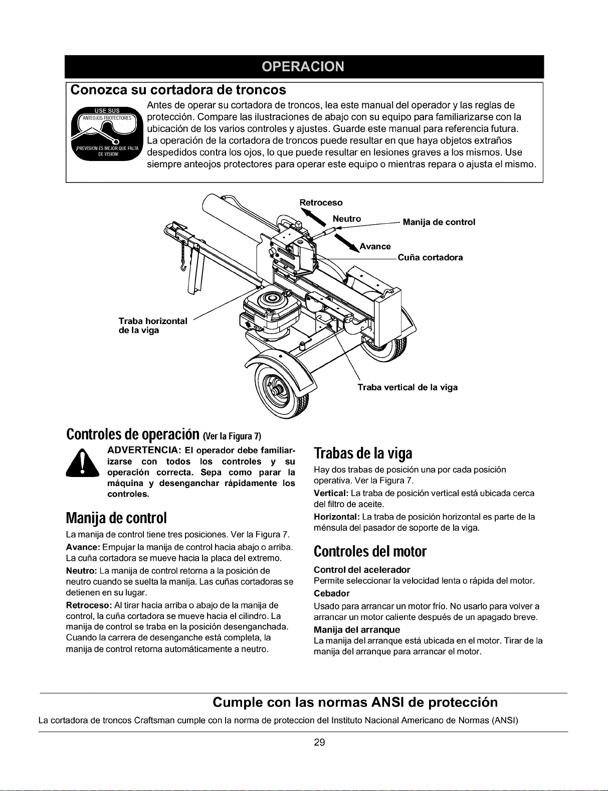
Conozca su cortadora de troncos
Antes de operar su cortadora de troncos, lea este manual del operador y las reglas de
protecci6n. Compare las ilustraciones de abajo con su equipo para familiarizarse con la
ubicaci6n de los varios controles y ajustes. Guarde este manual para referencia futura.
La operaci6n de la cortadora de troncos puede resultar en que haya objetos extraSos
despedidos contra los ojos, Io que puede resultar en lesiones graves a los mismos. Use
siempre anteojos protectores para operar este equipo o mientras repara o ajusta el mismo.
Retroceso
Neutro
_l_Avance
Manija de control
Cuba cortadora
Traba horizontal
de la viga
Traba vertical de la viga
Controlesdeoperacion(Ver la Figura7)
ADVERTENCIA: El operador debe familiar-
izarse con todos los controles y su
operacibn correcta. Sepa como parar la
m_quina y desenganchar r_pidamente los
controles.
Manijadecontrol
La manija de control tiene tres posiciones. Ver la Figura 7.
Avance: Empujar la manija de control hacia abajo o arriba.
La curia cortadora se mueve hacia la placa del extremo.
Neutro: La manija de control retoma a la posici6n de
neutrocuando se suelta lamanija. Las cutlas cortadorasse
detienen en su lugar.
Retroceso: AItirar hacia arriba o abajo de la manija de
control, lacuria cortadora se mueve hacia el cilindro.La
manija de control se traba en la posici6n desenganchada.
Cuando la carrera de desenganche est_ completa, la
manija de control retoma autom_ticamente a neutro.
Trabasdelaviga
Hay dos trabas de posici6n una por cada posici6n
operativa. Ver la Figura 7.
Vertical: La traba de posici6n vertical est_ ubicada cerca
del filtro de aceite.
Horizontal: La traba de posici6n horizontal es parte de la
m_nsula del pasador de soporte de la viga.
Controlesdelmotor
Control del acelerador
Permite seleccionar la velocidad lenta o r_pida del motor.
Cebador
Usado para arrancar un motor frio. No usarlo para volver a
arrancar un motor caliente despu_s de un apagado breve.
Manija del arranque
La manija del arranque est_ ubicada en el motor. Tirar de la
manija del arranque para arrancar el motor.
Cumple con las normas ANSI de proteccibn
La cortadora de troncos Craftsman cumple con la norma de proteccion del Instituto Nacional Americano de Normas (ANSI)
29
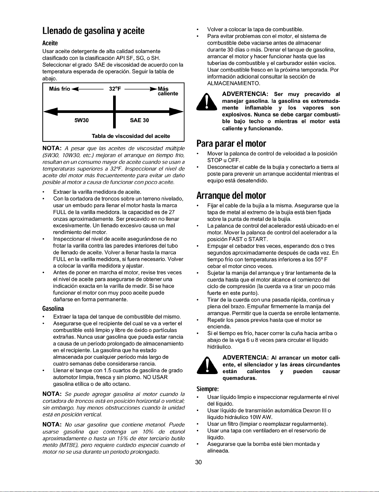
Llenadodegasolinay aceite
Aceite
Usar aceite detergente de alta calidad solamente
clasificado con la clasificaci6nAPI SF, SG, o SH.
Seleccionar el grado SAE de viscosidad de acuerdo con la
temperatura esperada de operaci6n. Seguir latabla de
abajo.
M_s frio _ 32°F _ M_s
caliente
5W30 SAE 30
liP"-
Tabla de viscosidad del aceite
NOTA: A pesar que las aceites de viscosidad mEfltiple
(5W30, 1014/30, etc.) mejoran el arranque en tiempo frio,
resultan en un consumo mayor de aceite cuando se usan a
temperaturas superiores a 32°F. Inspeccionar el nivel de
aceite del motor mas frecuentemente para evitar un dar_o
posible al motor a causa de funcionar con poco aceite.
• Extraer la varilla medidora de aceite.
• Con la cortadora de troncos sobre un terreno nivelado,
usar un embudo para Ilenar el motor hasta la marca
FULL de la varilla medidora, la capacidad es de 27
onzas aproximadamente. Ser precavido en no Ilenar
excesivamente. Un Ilenado excesivo causa un mal
rendimiento del motor.
• Inspeccionar el nivel de aceite asegur_ndose de no
frotar la varilla contra las paredes interiores del tubo
de Ilenado de aceite. Volver a Ilenar hasta la marca
FULL en la varilla medidora, si fuera necesario. Volver
a colocar la varilla medidora y ajustar.
• Antes de poner en marcha el motor, revise tres veces
el nivel de aceite para asegurarse de obtener una
indicaci6n exacta en la varilla de medir. Si se hace
funcionar el motor con muy poco aceite puede
dafiarse en forma permanente.
Gasolina
• Extraer latapa del tanque de combustible del mismo.
• Asegurarse que el recipiente del cual se va a verter el
combustible est6 limpioy libre de 6xido o particulas
extrafias. Nunca usar gasolina que pueda estar rancia
acausa de un periodo prolongado de almacenamiento
en el recipiente. La gasolina que ha estado
almacenada por cualquier periodo m_s largo de
cuatrosemanas debe considerarse rancia.
• Llenar el tanque con 1.5 cuartos de gasolina de grado
automotorlimpia, fresca y sin plomo. NO USAR
gasolina etilica o de alto octano.
NOTA: Se puede agregar gasolina al motor cuando la
cortadora de troncos esta en posicidn horizontal o vertical;
sin embargo, hay menos obstrucciones cuando la unidad
esta en posicidn vertical.
NOTA: No usar gasolina que contiene metanol. Puede
usarse gasolina que contenga un 10% de etanol
aproximadamente o hasta un 15% de 6ter terciario butilo
metilo (MTBE), pero requiere cuidado especial cuando el
motor no se usa durante un periodo prolongado.
Volver a colocar la tapa de combustible.
Para evitar problemas con el motor, el sistema de
combustible debe vaciarse antes de almacenar
durante 30 dias o m_s. Drenar el tanque de gasolina,
arrancar el motor y hacer funcionar hasta que las
tuberias de combustible y el carburador est_n vacios.
Usar combustible fresco en la pr6xima temporada. Por
informaci6n adicional consultar la secci6n de
ALMACENAMIENTO.
ADVERTENCIA: Ser muy precavido al
manejar gasolina, la gasolina es extremada-
mente inflamable y los vapores son
explosivos. Nunca se debe cargar combusti-
ble bajo techo o mientras el motor est_
caliente y funcionando.
Parapararelmotor
• Mover la palanca de control de velocidad a la posici6n
STOP u OFF.
• Desconectar el cable de la bujia y conectarlo a tierra al
poste para prevenir un arranque accidental mientras el
equipo est_ desatendido.
Arranquedelmotor
• Fijar el cable de la bujia a la misma. Asegurarse que la
tapa de metal al extremo de la bujia est_ bien fijada
sobre la punta de metal de la bujia.
• La palanca de controldel acelerador est_ ubicadoen el
motor. Mover la palanca de control del acelerador a la
posici6n FAST o START.
• Empujar el cebador tres veces, esperando dos o tres
segundos aproximadamente despu_s de cada vez. En
tiempo frio con temperaturas inferiores a los55° F
cebar el motor cinco veces.
• Sujetar la manija del arranque y tirar lentamente de la
cuerda hasta que el motor alcance el comienzo del
ciclode compresi6n (la cuerda va a tirar un poco m_s
fuerte en este punto).
• Tirar de la cuerda con una pasada r_pida, continua y
plena del brazo. Empufiar firmemente la manija del
arranque. Permitir que la cuerda se enrolle lentamente.
• Repetir los pasos previos hasta que el motorse
encienda.
• Si eltiempo es frio, hacer correr la curia hacia arriba o
abajo de la riga 6 u8 veces para circular el liquido
hidr_ulico.
ADVERTENCIA: AI arrancar un motor cali-
ente, el silenciador y las _reas circundantes
est_n calientes y pueden causar
quemaduras.
Siempre:
• Usar liquido limpio einspeccionar regularmente el nivel
del liquido.
• Usar liquido de transmisi6n autom_tica Dexron III o
liquido hidr_ulico 10W AW.
• Usar un filtro (limpiar o reemplazar regularmente).
• Usar una tapa con ventiladero en el reservorio de
liquido.
• Asegurarse que la bomba est_ bien montada y
alineada.
30
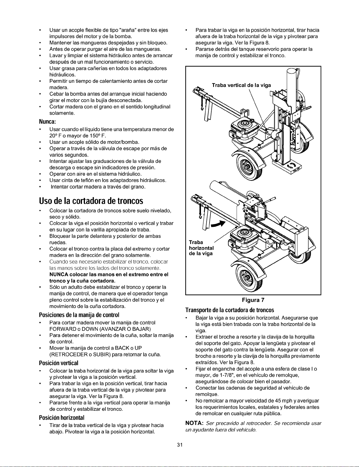
• Usar un acople flexible de tipo "arafia" entre los ejes
impulsores del motor y de la bomba.
• Mantener las mangueras despejadas y sin bloqueo.
• Antes de operar purgar el aire de las mangueras.
• Lavar y limpiar el sistema hidr_ulico antes de arrancar
despu_s de un mal funcionamiento o servicio.
• Usar grasa para cafierias en todos los adaptadores
hidr_ulicos.
• Permitir un tiempo de calentamiento antes de cortar
madera.
• Cebar la bomba antes del arranque inicial haciendo
girar el motor con la bujia desconectada.
• Cortar madera con el grano en el sentido longitudinal
solamente.
Nunca:
• Usar cuando el liquido tiene una temperatura menor de
20° F o mayor de 150° F.
• Usar un acople s61idode motor/bomba.
• Operar a trav_s de la v_lvula de escape por m_s de
varios segundos.
• Intentar ajustar las graduaciones de la v_lvula de
descarga o escape sin indicadores de presi6n.
• Operar con aire en el sistema hidr_ulico.
• Usar cinta de tefl6n en los adaptadores hidr_ulicos.
• Intentar cortar madera a trav_s del grano.
Usedelacortadoradetroncos
• Colocar la cortadora de troncos sobre suelo nivelado,
seco y s61ido.
• Colocar la viga el posici6n horizontal o vertical y trabar
en su lugar con la varilla apropiada de traba.
• Bloquear la parte delantera y posterior de ambas
ruedas.
• Colocar el tronco contra la placa del extremo y cortar
madera en la direcci6n del grano solamente.
• Cuando sea necesario estabilizar el tronco, colocar
las manos sobre los lados del tronco solamente,
NUNCA colocar las manos en el extremo entre el
tronco y la cuba cortadora.
• $61oun adulto debe estabilizar el tronco yoperar la
manija de control, de manera que el operador tenga
pleno controlsobre laestabilizaci6n del tronco yel
movimiento de lacuria cortadora.
Posicionesdelamanijadecontrol
• Para cortar madera mover la manija de control
FORWARD o DOWN (AVANZAR O BAJAR)
• Para detener el movimiento de la curia, soltar la manija
de control.
• Mover la manija de control a BACK o UP
(RETROCEDER o SUBIR) para retornar la curia.
Posici0nvertical
• Colocar latraba horizontal de lariga para soltar lariga
y pivotear la riga a la posici6n vertical.
• Para trabar la riga en la posici6n vertical, tirarhacia
afuera de la traba vertical de la riga y pivotear para
asegurar la riga. Ver la Figura 8.
• Pararse frente a la viga vertical para operar la manija
de control yestabilizar eltronco.
Posici0nhorizontal
• Tirar de latraba vertical de lariga y pivotear hacia
abajo. Pivotear la riga a la posici6n horizontal.
• Para trabar la viga en la posici6n horizontal, tirar hacia
afuera de la traba horizontal de la viga y pivotear para
asegurar la viga. Ver la Figura 8.
• Pararse detr_s del tanque reservorio para operar la
manija de control y estabilizar el tronco.
Traba vertical de la viga
Traba
horizontal
de la viga
Figura 7
Transportede la cortadora de troncos
• Bajar la riga a su posici6n horizontal. Asegurarse que
la riga est_ bien trabada con la traba horizontal de la
riga.
• Extraer el broche a resorte y la clavija de la horquilla
del soporte del gato. Apoyar la leng0eta y pivotear el
soporte del gato contra la leng0eta. Asegurar con el
broche a resorte y laclavija de la horquilla previamente
extraidos. Ver la Figura 8.
• Fijar el enganche del acople a una esfera de clase I o
mayor, de 1-7/8", en el vehiculo de remolque,
asegur_ndose de colocar bien el pasador.
• Conectar las cadenas de seguridad al vehiculode
remolque.
• No remolcar a mayor velocidad de 45 mph y averiguar
los requerimientos locales, estatales y federales antes
de remolcar en cualquier ruta peblica.
NOTA: Ser precavido al retroceder. Se recomienda usar
un ayudante fuera del vehfculo.
31
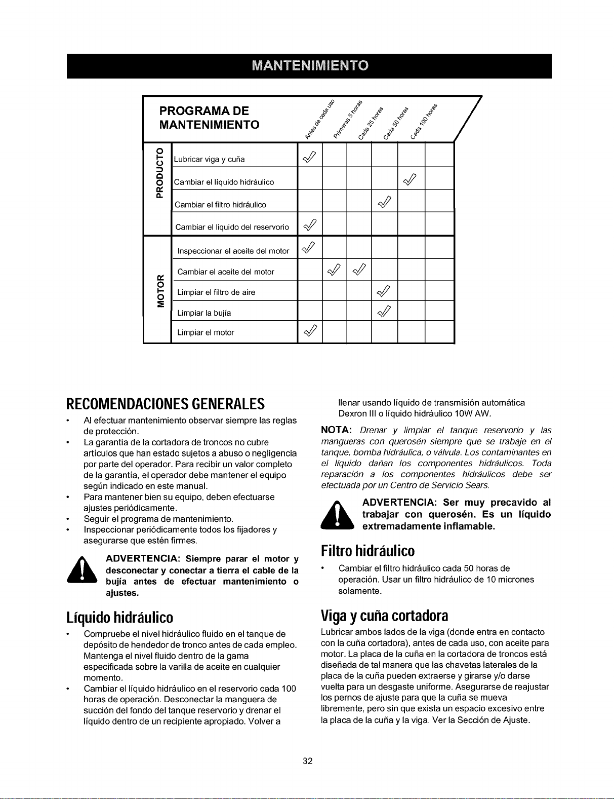
PROGRAMA DE f- _*o_ o._ **
MANTENIMIENTO _ 4 _ _÷
o
t_ Lubricarviga y cuba
8 Cambiar el liquidohidr_ulico
t_
n
Cambiar el filtro hidr_ulico
Cambiar el liquido del reservorio <_
Inspeccionarel aceite del motor
Cambiar el aceitedel motor _
t_
O
S Limpiar el filtro de aire
Limpiar la bujia
Limpiar el motor
RECOMENDACIONESGENERALES
• AI efectuar mantenimiento observar siempre las reglas
de protecci6n.
• La garantia de la cortadora de troncos no cubre
articulos que han estado sujetos a abuso o negligencia
por parte del operador. Para recibir un valor completo
de la garantia, el operador debe mantener el equipo
segt_n indicado en este manual.
• Para mantener bien su equipo, deben efectuarse
ajustes peri6dicamente.
• Seguir el programa de mantenimiento.
• Inspeccionar peri6dicamente todos los fijadores y
asegurarse que est_n firmes.
_, ADVERTENCIA: Siempre parar el motor y
desconectar y conectar a tierra el cable de la
bujia antes de efectuar mantenimiento o
ajustes.
Liquidohidraulico
• Compruebe el nivel hidr_ulico fluido en el tanque de
dep6sito de hendedor de tronco antes de cada empleo.
Mantenga el nivel fluido dentro de la gama
especificada sobre la varilla de aceite en cualquier
momento.
• Cambiar el liquido hidr_ulico en el reservorio cada 100
horas de operaci6n. Desconectar la manguera de
succi6n del fondo del tanque reservorio y drenar el
liquido dentro de un recipiente apropiado. Volver a
Ilenar usando liquido de transmisi6n autom_tica
Dexron III o liquido hidr_ulico 10W AW.
NOTA: Drenar y limpiar el tanque reservorio y las
mangueras con queros_n siempre que se trabaje en el
tanque, bomba hidraulica, o valvula. Los contaminantes en
el Ifquido dar_an los componentes hidraulicos. Toda
reparaci6n a los componentes hidraulicos debe ser
efectuada por un Centro de Servicio Sears.
,_ ADVERTENCIA: Ser muy precavido al
trabajar con queros6n. Es un liquido
extremadamente inflamable.
Filtrohidraulico
• Cambiar elfiltro hidr_ulico cada 50 horas de
operaci6n. Usar un filtro hidr_ulico de 10 micrones
solamente.
Vigaycuaacortadora
Lubdcar ambos lados de la riga (donde entra en contacto
con la curia cortadora), antes de cada uso,con aceite para
motor. La placa de la curia en la cortadora de troncos est_
disefiada de tal manera que las chavetas laterales de la
placa de la curia pueden extraerse y girarse y/o darse
vuelta para undesgaste uniforme. Asegurarse de reajustar
lospemos de ajuste para que la curia se mueva
libremente, pero sin que exista unespacio excesivo entre
la placa de la curia yla riga. Ver la Secci6n de Ajuste.
32
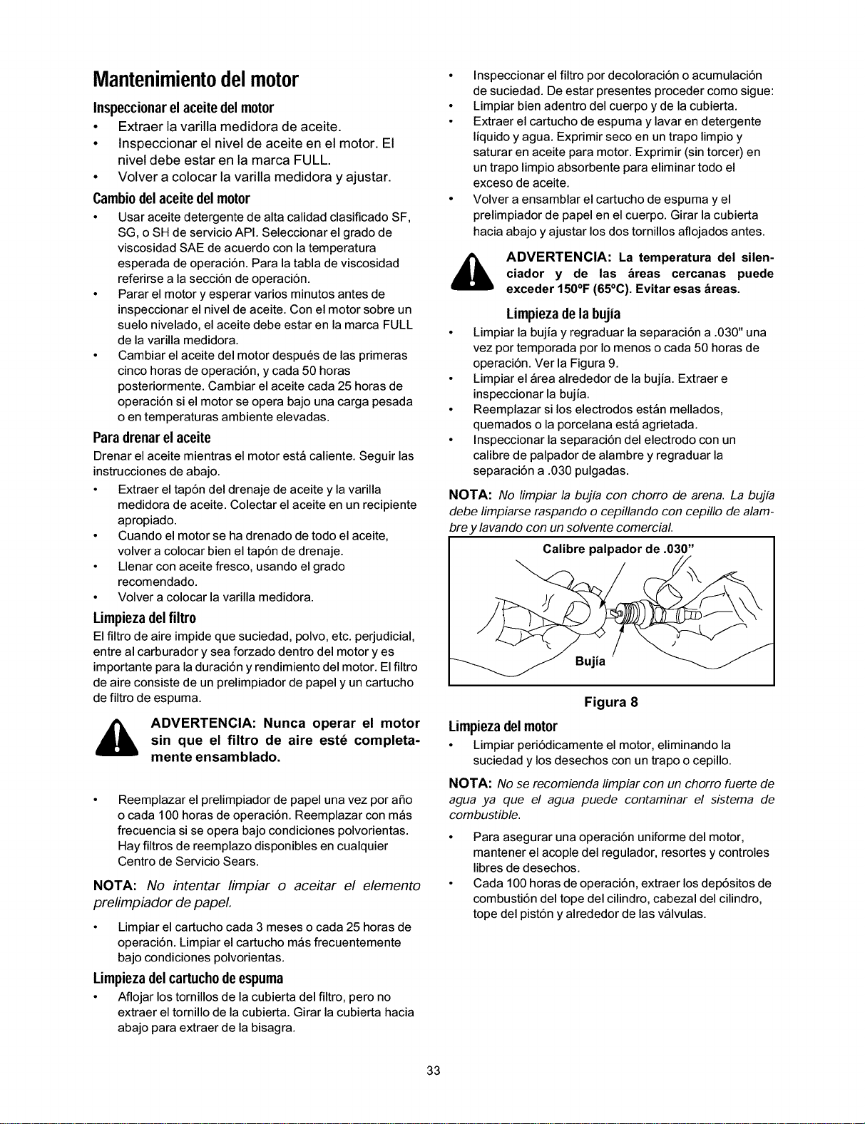
Mantenimientodelmotor
Inspeccionarelaceitedel motor
• Extraer la varilla medidora de aceite.
• Inspeccionar el nivel de aceite en el motor. El
nivel debe estar en la marca FULL.
• Volver a colocar la varilla medidora y ajustar.
Cambiodelaceite delmotor
• Usar aceite detergente de alta calidad clasificado SF,
SG, o SH de servicio API. Seleccionar el grado de
viscosidad SAE de acuerdo con la temperatura
esperada de operaci6n. Para la tabla de viscosidad
referirse a la secci6n de operaci6n.
• Parar el motor y esperar varios minutos antes de
inspeccionar el nivel de aceite. Con el motor sobre un
suelo nivelado, el aceite debe estar en la marca FULL
de la varilla medidora.
• Cambiar el aceite del motor despu_s de las primeras
cinco horas de operaci6n, y cada 50 horas
posteriormente. Cambiar el aceite cada 25 horas de
operaci6n si el motor se opera bajo una carga pesada
o en temperaturas ambiente elevadas.
Para drenarel aceite
Drenar el aceite mientras el motor est_ caliente. Seguir las
instrucciones de abajo.
• Extraer el tap6n del drenaje de aceite y la varilla
medidora de aceite. Colectar el aceite en un recipiente
apropiado.
• Cuando el motor se ha drenado de todo el aceite,
volver a colocar bien el tap6n de drenaje.
• Llenar con aceite fresco, usando el grado
recomendado.
• Volver a colocar la varilla medidora.
Limpieza delfiltro
El filtro de aire impide que suciedad, polvo, etc. perjudicial,
entre al carburador y sea forzado dentro del motor yes
importante para la duraci6n y rendimiento del motor. El filtro
de aire consiste de un prelimpiador de papel y un cartucho
de filtro de espuma.
ADVERTENCIA: Nunca operar el motor
sin que el filtro de aire estd completa-
mente ensamblado.
Reemplazar el prelimpiador de papel una vez por afio
o cada 100 horas de operaci6n. Reemplazar con m_s
frecuencia si se opera bajo condiciones polvorientas.
Hay filtros de reemplazo disponibles en cualquier
Centro de Servicio Sears.
NOTA: No intentar limpiar o aceitar el elemento
prelimpiador de papeL
• Limpiar el cartucho cada 3 meses o cada 25 horas de
operaci6n. Limpiar el cartucho m_s frecuentemente
bajo condiciones polvorientas.
Limpieza delcartuchodeespuma
• Aflojar los tornillos de la cubierta del filtro, pero no
extraer el tomillo de la cubierta. Girar la cubierta hacia
abajo para extraer de la bisagra.
• Inspeccionar el filtro por decoloraci6n o acumulaci6n
de suciedad. De estar presentes proceder como sigue:
• Limpiar bien adentro del cuerpo y de la cubierta.
• Extraer el cartucho de espuma y lavar en detergente
liquido y agua. Exprimir seco en un trapo limpio y
saturar en aceite para motor. Exprimir (sin torcer) en
un trapo limpio absorbente para eliminar todo el
exceso de aceite.
• Volver a ensamblar el cartucho de espuma y el
prelimpiador de papel en el cuerpo. Girar la cubierta
hacia abajo y ajustar los dos tornillos aflojados antes.
ADVERTENCIA: La temperatura del silen-
ciador y de las _reas cercanas puede
exceder 150°F (65°C). Evitar esas _reas.
Limpiezadelabujia
• Limpiar la bujia y regraduar la separaci6n a .030" una
vez por temporada por Io menos o cada 50 horas de
operaci6n. Ver la Figura 9.
• Limpiar el _rea alrededor de la bujia. Extraer e
inspeccionar la bujia.
• Reemplazar si los electrodos est_n mellados,
quemados o la porcelana est_ agrietada.
• Inspeccionar la separaci6n del electrodo con un
calibre de palpador de alambre y regraduar la
separaci6n a .030 pulgadas.
NOTA: No limpiar la bujfa con chorro de arena. La bujfa
debe limpiarse raspando o cepillando con cepillo de alam-
bre y lavando con un solvente comercial.
Calibre palpador de .030"
Figura 8
Limpieza del motor
• Limpiar peri6dicamente el motor, eliminando la
suciedad y losdesechos con untrapo o cepillo.
NOTA: No se recomienda limpiar con un chorro fuerte de
agua ya que el agua puede contaminar el sistema de
combustible.
• Para asegurar una operaci6n uniforme del motor,
mantener el acople del regulador, resortes y controles
libres de desechos.
• Cada 100 horas de operaci6n, extraer los dep6sitos de
combusti6n del tope del cilindro, cabezal del cilindro,
tope del pist6n y alrededor de las v_lvulas.
33
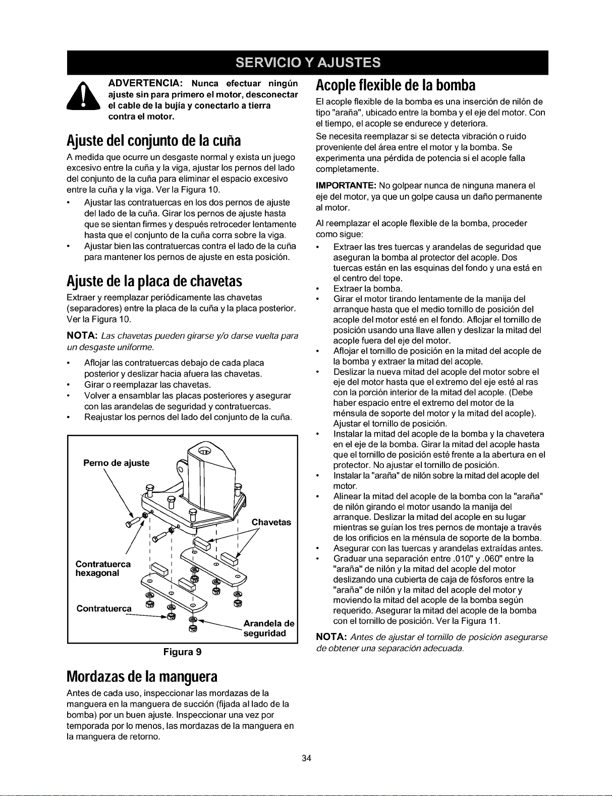
ADVERTENCIA: Nunca efectuar ningt_n
ajuste sin para primero el motor, desconectar
el cable de la bujia y conectarlo a tierra
contra el motor.
Ajustedelconjuntodelacuba
A medida que ocurre un desgaste normal y exista unjuego
excesivo entre lacuria y la riga, ajustar los pernosdel lado
del conjuntode la curia para eliminar el espacio excesivo
entre la curia y lariga. Ver la Figura 10.
• Ajustar las contratuercas en losdos pernos de ajuste
del lado de la curia. Girar los pernosde ajuste hasta
que se sientan firmes y despu_s retroceder lentamente
hasta que el conjuntode la curia corra sobre lariga.
• Ajustar bien lascontratuercas contra el lado de lacuria
para mantener lospernos de ajuste en esta posici6n.
Ajustedelaplacadechavetas
Extraer y reemplazar peri6dicamente las chavetas
(separadores) entre la placa de la curia y la placa posterior.
Ver la Figura 10.
NOTA: Las chavetas pueden girarse y/o darse vuelta para
un desgaste uniforme.
• Aflojar las contratuercas debajo de cada placa
posterior y deslizar hacia afuera las chavetas.
• Girar o reemplazar las chavetas.
• Volver a ensamblar las placas posteriores y asegurar
con las arandelas de seguridad y contratuercas.
• Reajustar los pernos del lado del conjunto de la curia.
Perno de ajuste
Chavetas
Contratuerca _£. _
hexagonal
Contratuerca
Arandela de
seguridad
Figura 9
Acopleflexibledelabomba
El acople flexible de la bomba es una inserci6n de nil6n de
tipo "arafia", ubicado entre la bombay el eje del motor. Con
el tiempo, el acople se endurece y deteriora.
Se necesita reemplazar si se detecta vibraci6n o ruido
proveniente del _rea entre el motor y la bomba. Se
experimenta una p_rdida de potencia si el acople falla
completamente.
IMPORTANTE: No golpear nunca de ninguna manera el
eje del motor, ya que un golpe causa un dafio permanente
al motor.
AI reemplazar el acople flexible de la bomba, proceder
como sigue:
• Extraer las tres tuercas y arandelas de seguridad que
aseguran la bomba al protector del acople. Dos
tuercas est_n en las esquinas del fondo y una est_ en
el centro del tope.
• Extraer la bomba.
• Girar el motor tirando lentamente de la manija del
arranque hasta que el medio tornillo de posici6n del
acople del motor est6 en el fondo. Aflojar el tornillo de
posici6n usando una Ilave allen y deslizar la mitad del
acople fuera del eje del motor.
• Aflojar el tornillo de posici6n en la mitad del acople de
la bomba y extraer la mitad del acople.
• Deslizar la nueva mitad del acople del motor sobre el
eje del motor hasta que el extremo del eje est_ al ras
con la porci6n interior de la mitad del acople. (Debe
haber espacio entre el extremo del motor de la
m_nsula de soporte del motor y la mitad del acople).
Ajustar el tornillo de posici6n.
• Instalar la mitad del acople de la bombay la chavetera
en el eje de la bomba. Girar la mitad del acople hasta
que el tornillo de posici6n est_ frente a la abertura en el
protector. No ajustar el tornillo de posici6n.
• Instalar la "arafia" de nil6n sobre la mitad del acople del
motor.
• Alinear la mitad del acople de la bomba con la "arafia"
de nil6n girando el motor usando la manija del
arranque. Deslizar la mitad del acople en su lugar
mientras se guian los tres pernos de montaje a trav6s
de los orificios en la m_nsula de soporte de la bomba.
• Asegurar con las tuercas y arandelas extraidas antes.
• Graduar una separaci6n entre .010" y .060" entre la
"arafia" de nil6n y la mitad del acople del motor
deslizando una cubierta de caja de f6sforos entre la
"arafia" de nil6n y la mitad del acople del motor y
moviendo la mitad del acople de la bomba seg6n
requerido. Asegurar la mitad del acople de la bomba
con el tornillo de posici6n. Ver la Figura 11.
NOTA: Antes de ajustar el tornfllo de posici6n asegurarse
de obtener una separaci6n adecuada.
Mordazasdelamanguera
Antes de cada uso, inspeccionar las mordazas de la
manguera en la manguera de succi6n (fijada al lado de la
bomba) por un buen ajuste. Inspeccionar una vez por
temporada por Io menos, las mordazas de la manguera en
la manguera de retorno.
34
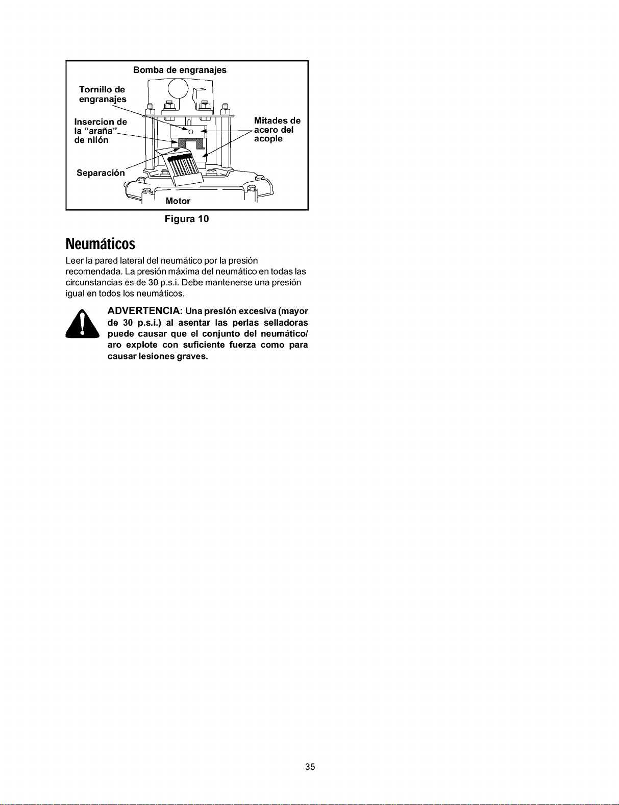
Bomba de engranajes
Tornillo de
I_g_ i_ Mitades de
la "arafia"_ I Itl I -"_o _acero del
de nilbn _ acople
Separaci6n_
Figura 10
Neumatic0s
Leer la pared lateral del neum_tico por la presi6n
recomendada. La presi6n m_xima del neum_tico en todas las
circunstancias es de 30 p.s.i. Debe mantenerse una presi6n
igual en todos los neum_ticos.
ADVERTENCIA: Una presibn excesiva (mayor
de 30 p.s.i.) al asentar las perlas selladoras
puede causar que el conjunto del neum_tico/
aro explote con suficiente fuerza como para
causar lesiones graves.
35
AIfinal de la temporada o si la cortadora de troncos no se va
a usar por 30 dias o m_s, prepararla para almacenamiento.
ADVERTENCIA: Nunca almacenar la
m_quina con combustible en el tanque de
combustible dentro de un edificio donde los
humos pueden alcanzar una llama expuesta o
chispa o donde est_n presentes fuentes de
encendido tales como calentadores de agua
caliente y espacio, calderas, secadoras de
ropa, cocinas, motores el_ctricos, etc.
NOTA: Una buena manera de asegurar que su cortadora
de troncos proporcionara un rendimiento maximo la
prdxima temporada es una revisacidn anual por su Centro
de Servicio Sears local.
Cortadoradetroncos
• Limpiar bien la cortadora de troncos
• Frotar la unidad con untrapo aceitado para prevenir la
oxidaci6n, especialmente en lacuSa y riga.
Motor
IMPORTANTE: Es importante prevenir que se formen
dep6sitos de goma en las piezas esenciales del sistema de
combustible tales como carburador, filtro de combustible,
manguera de combustible, o tanque, durante el
almacenamiento. Tambi_n, las mezclas de alcohol
(llamadas gasohol o el uso de etanol o metanol) puede
atraer humedad que conduce a la separaci6n y formaci6n
de _cidos durante el almacenamiento. El gas acidico puede
daSar el sistema de combustible del motor mientras est_
almacenado.
• Drenar el tanque de combustible. Siempre drenar el
combustible dentro de un recipiente aprobado al aire
libre, alejado de llamas expuestas. Asegurarse que el
motor est_ frio. No fumar mientras se maneja el
combustible.
• Arrancar el motor y dejarlo funcionar hasta que las
tuberias de combustible y el carburador est_n vacios.
• Nunca usar productos limpiadores de motor o
carburador en el tanque de combustible ya que puede
ocurrir un daSo permanente. Usar combustible fresco
la temporada pr6xima.
• Extraer la bujia, verter 1/2 oz aproximadamente de
aceite para motor dentro del cilindro y hacer girar
lentamente para distribuir el aceite.
• Volver acolocar la bujia.
NOTA: El estabilizador de combustible es una alternativa
aceptable para minimizar la formaci6n de dep6sitos de
goma de combustible durante el almacenamiento.
Por favor seguir las instrucciones de abajo para almacenar
su cortadora de troncos con combustible y estabilizador en
el motor.
• Agregar estabilizador a la gasolina en el tanque de
combustible o recipiente de almacenamiento.
• Seguir siempre la proporci6n de mezcla indicada en el
recipiente del estabilizador.
• Hacer funcionar el motor por 10 minutos por Io menos
despu6s de agregar estabilizador para permitir que el
estabilizador Ilegue al carburador.
• No drenar el tanque de gasolina y el carburador si se
usa estabilizador de combustible. Drenar todo el
aceite del c_rter (esto debe hacerse despu_s de
operar el motor y cuando est_ todavia caliente) y
Ilenar el c_rter con aceite fresco.
0tros
• No almacenar la gasolina de una temporada a la otra.
• Reemplazar el recipiente de gasolina si comienza a
oxidarse.
• Almacenar la unidad en un _rea limpia yseca. No
almacenar cerca de materiales corrosivostales como
fertilizante.
• Frotar elequipo con untrapo aceitado para prevenir la
oxidaci6n.
36
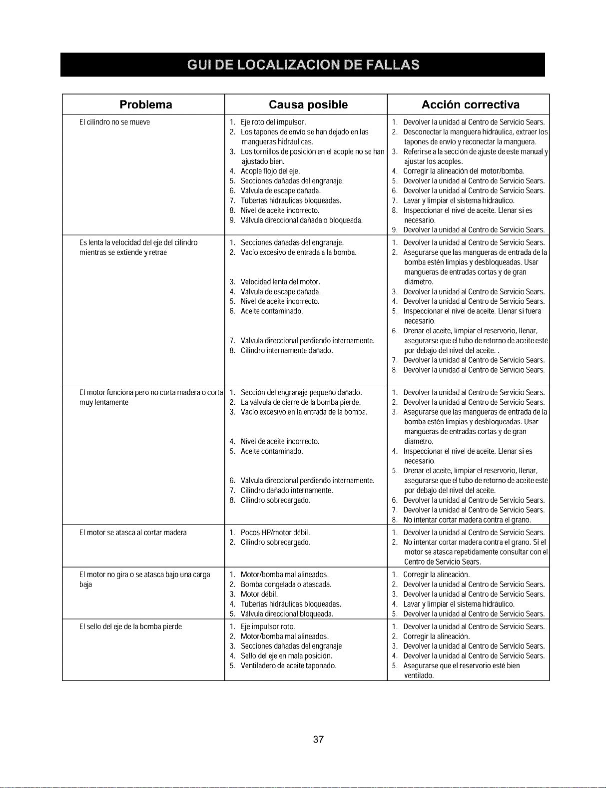
Problema Causa posible Accibn correctiva
El cilindro nose mueve
1. Ejeroto del impulsor.
2. Lostapones deenviose handejadoenlas
manguerashidr_ulicas.
3. Los tornillos deposici0n enel acoplenose han
ajustado bien.
4. Acopleflojo deleje.
5. Seccionesdahadasdel engranaje.
6. V_lvuladeescapedahada.
7. Tuberias hidr_ulicas bloqueadas.
8. Nivel deaceite incorrecto.
9. V_lvuladireccional dahadao bloqueada.
1. Seccionesdahadasdel engranaje.
2. vacio excesivodeentradaala bomb&
Es lentalavelocidad deleje delcilindro
mientras se extiendey retrae
El motor funciona pero nocorta maderaocorta
muy lentamente
El motor se atascaal cortar madera
El motor nogira o seatasca bajouna carga
baja
El sellodel ejedela bomba pierde
3. Velocidadlentadel motor.
4. Valvuladeescapedahada.
5. Nivel deaceite incorrecto.
6. Aceitecontaminado.
7. V_lvuladireccional perdiendo internamente.
8. Cilindro internamentedahado.
1. Secci0ndel engranajepequehodahado.
2. Lav_lvuladecierre de labomba pierde.
3. Vacio excesivoenla entradadela bomb&
4. Nivel deaceite incorrecto.
5. Aceitecontaminado.
6. V_lvuladireccional perdiendo internamente.
7. Cilindro dahadointernamente.
8. Cilindro sobrecargado.
1. Pocos HP/motor debil.
2. Cilindro sobrecargado.
1. Motor/bomba malalineados.
2. Bombacongeladao atascada.
3. Motor debil.
4. Tuberias hidraulicas bloqueadas.
5. Valvuladireccional bloqueada.
1. Ejeimpulsorroto.
2. Motor/bomba malalineados.
3. Seccionesdahadasdel engranaje
4. Sello del ejeenmala posici0n.
5. Ventiladerode aceitetaponado.
1. Devolverla unidad al CentrodeServicio Sears.
2. Desconectarlamanguerahidraulica,extraer los
tapones deenvioy reconectar lamanguera.
3. Referirsealasecci0ndeajuste deestemanualy
ajustarlos acoples.
4. Corregir la alineaci0ndel motor/bomb&
5. Devolverla unidad al CentrodeServicio Sears.
6. Devolverla unidad al CentrodeServicio Sears.
7. Lavary limpiarel sistema hidraulico.
8. Inspeccionarel niveldeaceite.Llenarsi es
necesario.
9. Devolverla unidad al CentrodeServicio Sears.
1. Devolverla unidad al CentrodeServicio Sears.
2. Asegurarsequelas manguerasde entradade la
bomba estenlimpiasy desbloqueadas.Usar
manguerasdeentradascortasy degran
di_metro.
3. Devolverla unidad al CentrodeServicio Sears.
4. Devolverla unidad al CentrodeServicio Sears.
5. Inspeccionarel niveldeaceite.Llenarsi fuera
necesario.
6. Drenarel aceite,limpiar el reservorio, Ilenar,
asegurarsequeeltubo deretorno deaceiteeste
pot debajodel nivel del aceite..
7. Devolverla unidad al CentrodeServicio Sears.
8. Devolverla unidad al CentrodeServicio Sears.
1. Devolverla unidad al CentrodeServicio Sears.
2. Devolverla unidad al CentrodeServicio Sears.
3. Asegurarsequelas manguerasde entradade la
bomba estenlimpiasy desbloqueadas.Usar
manguerasdeentradascortasy degran
diametro.
4. Inspeccionarel niveldeaceite.Llenarsi es
necesario.
5. Drenarel aceite,limpiar el reservorio, Ilenar,
asegurarsequeeltubo deretorno deaceiteeste
pot debajodel nivel del aceite.
6. Devolverla unidad al CentrodeServicio Sears.
7. Devolverla unidad al CentrodeServicio Sears.
8. Nointentar cortar maderacontra el grano.
1. Devolverla unidad al CentrodeServicio Sears.
2. Nointentar cortar maderacontra el grano. Siel
motor seatasca repetidamenteconsultar con el
CentrodeServicioSears.
1. Corregir la alineaci0n.
2. Devolverla unidad al CentrodeServicio Sears.
3. Devolverla unidad al CentrodeServicio Sears.
4. Lavary limpiarel sistema hidr_ulico.
5. Devolverla unidad al CentrodeServicio Sears.
1. Devolverla unidad al CentrodeServicio Sears.
2. Corregir la alineaci0n.
3. Devolverla unidad al CentrodeServicio Sears.
4. Devolverla unidad al CentrodeServicio Sears.
5. Asegurarsequeel reservorio este bien
ventilado.
37
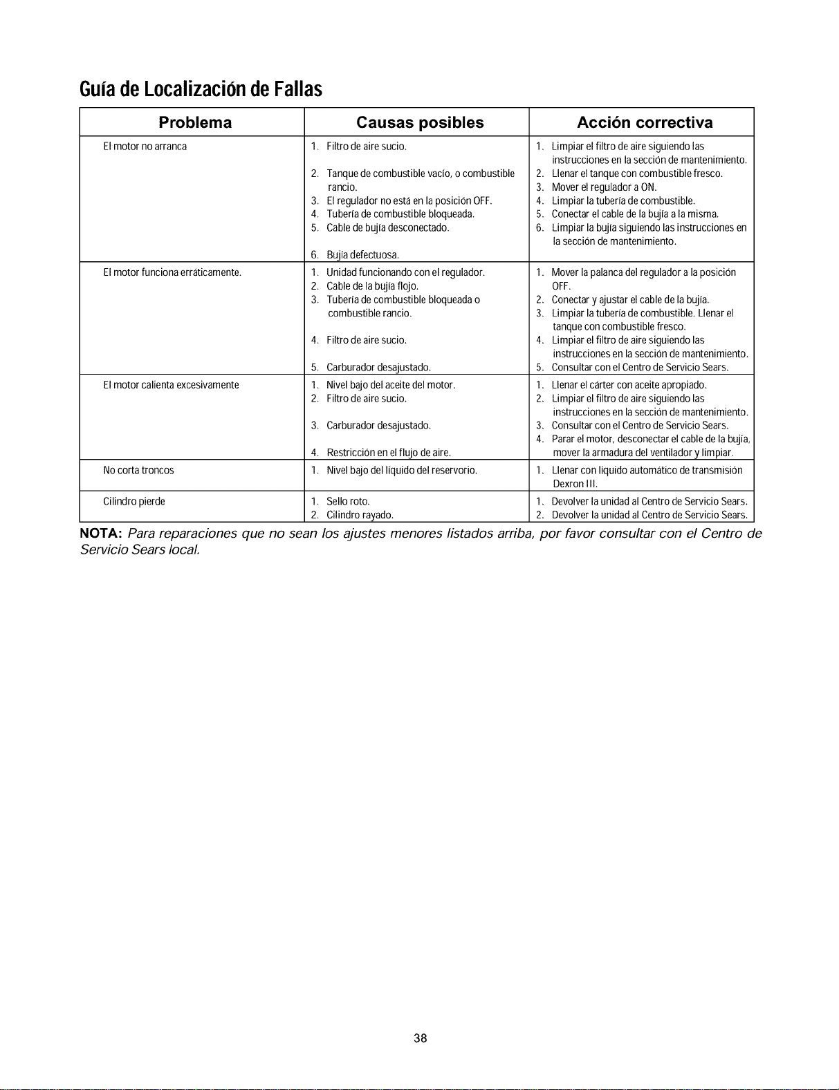
GuiadeLocalizaciondeFallas
Problema Causas posibles Accibn correctiva
Elmotor no arranca 1. Filtro de aire sucio. 1.
Elmotor funciona erraticamente.
Elmotor calientaexcesivamente
2. Tanquede combustible vacio, ocombustible
rancio.
3. El reguladornoesta enla posici0nOFF.
4. Tuberiadecombustible bloqueada.
5. Cabledebujiadesconectado.
6. Bujia defectuosa.
1. Unidadfuncionando con el regulador.
2. Cabledela bujiaflojo.
3. Tuberiadecombustible bloqueadao
combustible rancio.
4. Filtro de aire sucio.
5. Carburador desajustado.
1. Nivel bajo delaceite del motor.
2. Filtro de aire sucio.
3. Carburador desajustado.
4. Restricci0nenelflujo deaire.
1. Nivel bajo del liquido del reservorio.
Nocorta troncos
Cilindro pierde 1. Selloroto.
2. Cilindro rayado.
NOTA: Para reparaciones que no sean los ajustes menores listados arriba
Servicio Sears local.
Limpiar el filtro deaire siguiendo las
instrucciones enla secci0ndemantenimiento.
2. Llenar eltanque con combustiblefresco.
3. Mover elreguladoraON.
4. Limpiar la tuberiadecombustible.
5. Conectarel cabledela bujiaala misma.
6. Limpiar la bujiasiguiendo las instrucciones en
la secci0n demantenimiento.
1. Mover lapalancadel reguladorala posici0n
OFF.
2. Conectary ajustar elcablede la bujia.
3. Limpiar la tuberiadecombustible. Llenarel
tanquecon combustible fresco.
4. Limpiar el filtro deairesiguiendo las
instrucciones enla secci0ndemantenimiento.
5. Consultarcon el CentrodeServicio Sears.
1. Llenar elcarter con aceiteapropiado.
2. Limpiar el filtro deairesiguiendo las
instrucciones enla secci0ndemantenimiento.
3. Consultarcon el CentrodeServicio Sears.
4. Pararel motor, desconectarel cabledela bujia,
mover la armaduradel ventilador y limpiar.
1. Llenar con liquido automatico detransmisi0n
DexronIII.
1. Devolverla unidad al CentrodeServicio Sears.
2. Devolver launidad al CentrodeServicio Sears.
por favor consultar con el Centro de
38

39

In U.S.A. or Canada
for in-home major brand repair service:
Call 24 hours a day, 7 days a week
1-800-4-MY-HOME SM(1-800-469-4683)
Para pedir servicio de reparacibn a domicilio- 1-800-676-5811
Au Canada pour tout le service ou les pi_ces - 1-800-469-4663
For the repair or replacement parts you need:
Call 6 a.m. - 11 p.m. CST, 7 days a week
PartsDirect
1-800-366-PART (1-800-366-7278)
Para ordenar piezas con entrega a domicilio - 1-800-659-7084
For the location of a Sears Service Center in your area:
Call 24 hours a day, 7 days a week
1-800-488-1222
To purchase or inquire about a Sears Maintenance Agreement:
Call 7 a.m. - 5 p.m. CST, Monday - Saturday
1-800-827-6655
SEARS
HomeCentral
