

120e Mark II
EN Operator's manual 8-21
28
27
8
2
3
4
29
5
6
79 10 11 12 13
26
16 17 18
19
20
21
22
23
14
1
15
24 25
1
2 3 4 5 6 7
8 9 10 11 12 13
14 15 16
NOISE dBA
17 18 19
20 21 22
23
24
25
26
27
28
29
30
31
32
33
34
35
36
37
A
B
38
A
39
40
41
42
43
44
45
46
A
47
48
49
50
51
52
53
54
55
56
57
58
59
60
61
62
63
X
64
Y
65
66
67
68
69
70
71
72
73
74
75
76
77
78
A
79
C
D
80
81
A
B
C
82
A
83
A
84
85
Ø
86
A
87
A
B
C
88
89
90
91
92
93
94
95
96
97
98

Contents
Introduction..................................................................... 8
Safety..............................................................................9
Assembly...................................................................... 13
Operation...................................................................... 14
Maintenance................................................................. 16
Transportation...............................................................19
Storage......................................................................... 19
Technical data.............................................................. 19
Accessories.................................................................. 20
Introduction
Operator's manual
The initial language of this operator's manual is English.
Operator's manuals in other languages are translations
from English.
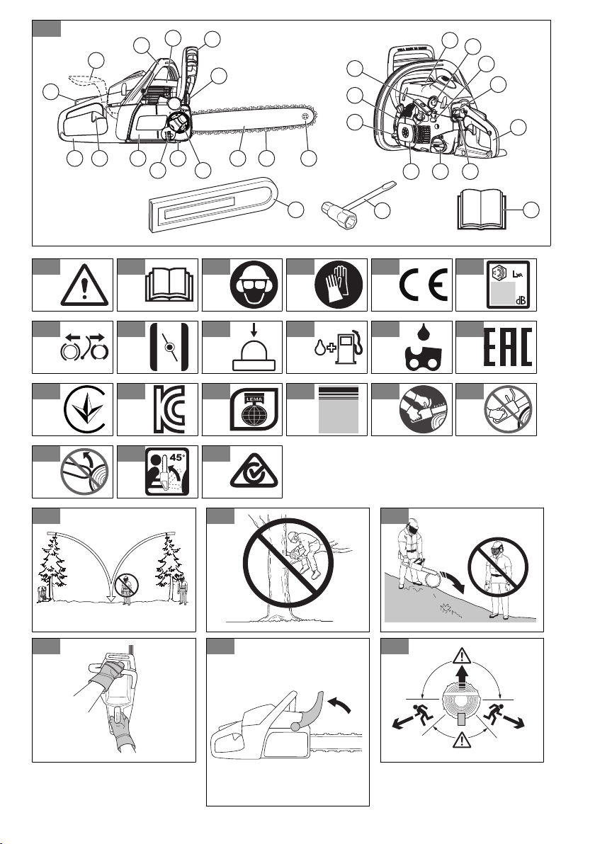
Overview
(Fig. 1)
1. Product and serial number plate
2. Trigger lockout
3. Front handle
4. Cylinder cover
5. Chain brake and front hand guard
6. Muffler
7. Bar nose sprocket
8. Right hand guard
9. Trigger
10. Clutch cover
11. Chain catcher
12. Guide bar
13. Saw chain
14. Starter handle
15. Chain oil tank
16. Starter
17. Fuel tank
18. Choke control
19. Rear handle
20. Stop switch
21. Idle adjustment screw
22. Primer bulb
23. Information and warning decal
24. Chain tensioner wheel
25. Knob
26. Guide-bar cover
27. Combination tool
28. Operator's manual
29. Right-hand brake trigger (some models)
Symbols on the product
(Fig. 2)
Warning
(Fig. 3)
Read this manual
(Fig. 4)
Use approved head protection, hearing
protection and eye protection
(Fig. 5)
Use approved protective gloves
(Fig. 6)
The product agrees with the applicable
EC Directives
(Fig. 7)
Sound power level
(Fig. 8)
Chain brake, not engaged (left). Chain
brake, engaged (right)
(Fig. 9)
Choke control
(Fig. 10)
Air purge bulb
(Fig. 11)
Refuelling
(Fig. 12)
Chain oil fill
(Fig. 13)
This product agrees with the applicable
EAC directives
(Fig. 14)
This product agrees with the applicable
Ukraine directives
(Fig. 15)
This product agrees wtih the applicable
Korea directives
(Fig. 16)
This product agrees wtih the applicable
Japan directives
(Fig. 17)
Noise level
(Fig. 18)
Hold the product properly with both hands
(Fig. 19)
Do not use with one hand
8 653 - 010 - 10.07.2023
(Fig. 20)
Avoid contact with nose of guide bar
(Fig. 21)
Beware of kickback
(Fig. 22)
This product agrees with the
applicable Australia and New Zealand
electromagnetic compatibility directives.
Note: Other symbols/decals on the product refer to
certification requirements for other commercial areas.
Product liability
As referred to in the product liability laws, we are not
liable for damages that our product causes if:
• the product is incorrectly repaired.
• the product is repaired with parts that are not
from the manufacturer or not approved by the
manufacturer.
• the product has an accessory that is not from the
manufacturer or not approved by the manufacturer.
• the product is not repaired at an approved service
center or by an approved authority.
Safety
Safety definitions
The definitions below give the level of severity for each
signal word.
WARNING: Injury to persons.
CAUTION: Damage to the product.
Note: This information makes the product easier to
use.
General safety instructions
• Use the product correctly. Injury or death is a
possible result of incorrect use. Only use the product
for the tasks found in this manual. Do not use the
product for other tasks.
• Read, understand and obey the instructions in this
manual. Obey the safety symbols and the safety
instructions. If the operator does not obey the
instructions and the symbols, injury, damage or
death is a possible result.
• Do not discard this manual. Use the instructions
to assemble, to operate and to keep your product
in good condition. Use the instructions for correct
installation of attachments and accessories. Only
use approved attachments and accessories.
• Do not use a damaged product. Obey the
maintenance schedule. Only do the maintenance
work that you find an instruction about in this
manual. An approved service center must do all
other maintenance work.
• This manual cannot include all situations that can
occur when you use the product. Be careful and use
your common sense. Do not operate the product or
do maintenance to the product if you are not sure
about the situation. Speak to a product expert, your
dealer, service agent or approved service center for
information.
• Disconnect the spark plug cable before you
assemble the product, put the product into storage
or do maintenance.
• Do not use the product if it is changed from its initial
specification. Do not change a part of the product
without approval from the manufacturer. Only use
parts that are approved by the manufacturer.
Injury or death is a possible result of incorrect
maintenance.
• Do not breathe in the exhaust fumes from the
engine. A health risk can occur if you breathe in
exhaust fumes, chain oil fumes and sawdust for a
long period.
• Do not start the product indoors or near flammable
material. The exhaust fumes are hot and can contain
a spark which can start a fire. Without sufficient
airflow, injury or death can result from asphyxiation
or carbon monoxide.
• This product makes an electromagnetic field during
operation. The electromagnetic field can cause
damage to medical implants. Speak to your
physician and medical implant manufacturer before
you operate the product.
• Do not let a child operate the product.
• Do not let a person, without knowledge of the
instructions, operate the product.
• Always monitor a person, with decreased physical
capacity or mental capacity, that uses the product. A
responsible adult must be there at all times.
• Lock the product in an area that children and not
approved persons cannot access.
• The product can eject objects and cause injuries.
Obey the safety instructions to decrease the risk of
injury or death.
653 - 010 - 10.07.2023
9

• Do not go away from the product when the engine
is on. Stop the engine and make sure that the chain
does not rotate.
• The operator of the product is responsible if an
accident occurs.
• Make sure that parts are not damaged before you
use the product.
• Refer to national or local laws. They can prevent
or decrease the operation of the product in some
conditions.
Safety instructions for operation
• Continuous or regular operation of the product
can cause "white finger" or equivalent medical
problems from vibrations. Examine the condition of
your hands and fingers if you operate the product
continuously or regularly. If your hands or fingers
have discoloration, have pain, tingle, or are numb,
stop work and speak to a physician immediately.
• Make sure the product is fully assembled before you
use it.
• The product can cause objects to eject, which can
cause damage to the eyes. Always use approved
eye protection when you operate the product.
• Be careful, a child can come near the product
without your knowledge during operation.
• Do not operate the product if there are persons in
the work area. Stop the product if a person goes into
the work area.
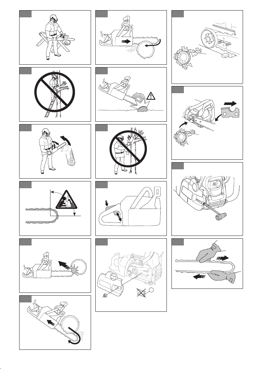
(Fig. 23)
• Make sure that you are always in control of the
product.
• The product must be operated with two hands. Do
not operate the product with one hand. Serious
injury to the operator, workers, bystanders, or a
combination of these persons may result from
operation with only one hand.
• Hold the front handle with your left hand and the rear
handle with your right hand. Hold the product on the
right side of your body.
(Fig. 24)
• Do not operate the product when you are fatigued, ill
or under the influence of alcohol or other drugs.
• Do not use the product if you cannot receive aid if
an accident occurs. Make others aware that you will
operate the product before you start the product.
• Do not turn with the product before you make sure
that no persons or animals are in the safety area.
• Remove all unwanted materials from the work area
before you start. If the chain hits an object, the object
can eject and cause injury or damage. Unwanted
material can wind around the chain and cause
damage.
• Do not use the product in bad weather, such as fog,
rain, strong winds, risk of lightning or other weather
conditions. Dangerous conditions, such as slippery
surfaces, can occur because of bad weather.
• Make sure that you can move freely and work in a
stable position.
• Make sure that you cannot fall when you use the
product. Do not tilt when you operate the product.
• Always hold the product with your two hands. Hold
the front handle with your left hand and the rear
handle with your right hand. Hold the product on the
right side of your body.
• If the choke control is in the choke position when the
engine starts, the chain starts to turn.
• Stop the engine before you move the product.
• Do not put down the product with the engine on.
• Before you remove the unwanted materials from the
product, stop the engine. Let the chain stop before
you or another person can remove the cut material.
• Do not operate this product in a tree. Operation of
the product while up in a tree may result in personal
injury.
(Fig. 25)
• The chain brake must be engaged when the product
is started to decrease the risk that the saw chain
touches you during start.
(Fig. 26)
• Avoid kickback, skating, bouncing and dropping,
which can result in serious injury.
• Obey all safety rules to help avoid kickback and
other forces which can result in serious injury.
• Adjust the saw chain tension regularly to make sure
that the saw chain does not slack. A slack saw chain
may jump off and cause serious injury or death.
• Do not fell trees using an incorrect procedure. This
can cause injury to persons, hit a utility line or cause
damage to property.
• The operator should remain on the uphill side of the
terrain as the tree is likely to roll or slide downhill
after it is felled.
(Fig. 27)
• Plan and clear an escape path before cuts are
started. The escape path should extend back and
diagonally to the rear of the expected line of fall.
(Fig. 28)
• Always stop the engine before you move the product
between the trees.
• Make sure you firmly plant your feet on the ground
and distribute your weight evenly.
(Fig. 29)
• Always keep proper footing and operate the product
only when standing on fixed, secure and level
surface. Slippery or unstable surfaces such as
ladders may cause a loss of balance or control.
(Fig. 30)
Kickbacks, skating, bouncing and dropping
Different forces can have an effect on the safe control of
the product.
10
653 - 010 - 10.07.2023

• Skating is when the guide bar glides or moves
quickly across the wood.
• Bouncing is when the guide bar lifts off the wood and
touches it again and again.
• Dropping is when the product drops down after the
cut is made. This can cause the moving chain to
touch a part of the body or other objects, causing
injury or damage.
• Kickback is when the end of the guide bar touches
objects and moves rearward, up or suddenly
forward. Kickback also occurs when the wood closes
in and pinches the saw chain during the cut. Loss of
control can result if the product touches an object in
wood.
(Fig. 31)
• Rotational Kickback can occur when the moving
chain touches an object at the top of the guide
bar. This can cause the chain to bury into the
object and cause the chain to stop immediately.
The result is a very fast, reverse reaction that
moves the guide bar up and rearward in the
direction of the operator.
(Fig. 32)
(Fig. 33)
• Pinch-Kickback can occur when the saw chain
suddenly stops during the cut. The wood closes
in and pinches the moving saw chain along the
top of the guide bar. The sudden stop of the
chain reverses the chain force and causes the
product to move in the opposite direction of the
turn of the chain. The product moves rearward in
the direction of the operator.
(Fig. 34)
• Pull-In can occur when the saw chain suddenly
stops when the moving chain touches an object
in the wood along the bottom of the guide bar.
The sudden stop pulls the product forward and
away from the operator, which can easily cause
the loss of control of the product by the operator.
(Fig. 35)
Make sure that you understand the different forces and
how to prevent them before you operate the product.
To prevent kickbacks, skating, bouncing and
dropping
• While the engine runs, make sure to hold the product
tightly. Keep your right hand on the rear handle and
the left hand on the front handle. Tightly hold with
thumbs and fingers around the handles. Do not let
go.
• Keep control of the product during the cut and after
the wood falls to the ground. Do not let the weight
of the product drop down after the cut is made. (Fig.
36)
• Make sure that the area in which you are cutting is
free from blockage. Do not let the nose of the guide
bar touch a log, branch or other blockages while you
operate the product.
• Cut at high engine speeds.
• Do not overreach or cut above shoulder height. (Fig.
37)
• Obey the manufacturer's sharpening and
maintenance instructions for the saw chain.
• Only use replacement guide bars and saw chains
specified by the manufacturer.
• The risk of kickback is increased if the depth gauge
setting is too large.
Personal protective equipment
• Always use the correct personal protective
equipment when you operate the product. The
personal protective equipment does not erase the
risk of injury. The personal protective equipment
decreases the grade of injury if an accident occurs.
• Generally, clothes should be close-fitting without
restricting your freedom of movement.
• Use an approved protective helmet.
• Always use approved ear protection while you
operate the product. Noise for a long period can
cause hearing loss.
• Use protective glasses or a face visor to reduce the
risk of injury from thrown objects. The product is
capable of throwing objects, such as wood chips,
small pieces of wood, etc., at great force. This can
result in serious injury, especially to the eyes.
• Use gloves with chainsaw protection.
• Use trousers with chainsaw protection.
• Use boots with chainsaw protection, steel toe-cap
and non-slip sole.
• Make sure that you have a first aid kit near.
• Sparks can come from the muffler, the guide bar
and saw chain or other sources. Always have fire
extinguishing tools and a shovel available to help
prevent forest fires.
Protective devices on the product
• Make sure that you regularly do the maintenance to
the product.
• The life of the product increases.
• The risk of accidents decreases.
Let an approved dealer or an approved service
center regularly examine the product to do
adjustments or repairs.
• Do not use a product with damaged protective
equipment. If the product is damaged, speak to an
approved service center.
Stop switch
Start the engine. Make sure that the engine stops when
you move the stop switch to the stop position.
653 - 010 - 10.07.2023
11

To examine the throttle trigger lockout
1. Make sure that the trigger (B) is locked at idle when
you release the trigger lockout (A). (Fig. 38)
2. Push the trigger lockout (A) and make sure that it
goes back to its initial position when you release it.
3. Push the trigger (B) and make sure that it goes back
to its initial position when you release it.
4. Start the engine, and then apply full speed.
5. Release the trigger and examine if the saw chain
stops.
6. If the saw chain turns with an idle engine, examine
the idle adjustment screw of the carburetor.
Guard
The guard prevents objects from being ejected in the
direction of the operator. The guard also prevents
accidental touch between the operator and the saw
chain.
• Make sure that the guard is permitted for operation
in combination with the product.
• Do not use the product without the guard.
• Make sure that the guard is not damaged. Replace
the guard if it is worn or has cracks.
Fuel safety
• Do not start the product if there is fuel or engine oil
on the product. Remove the unwanted fuel/oil and
let the product dry. Remove unwanted fuel from the
product.
• If you spill fuel on your clothing, change clothing
immediately.
• Do not get fuel on your body, it can cause injury. If
you get fuel on your body, use a soap and water to
remove the fuel.
• Do not start the engine if you spill oil or fuel on the
product or on your body.
• Do not start the product if the engine has a leak.
Examine the engine for leaks regularly.
• Be careful with fuel. Fuel is flammable and the fumes
are explosive and can cause injuries or death.
• Do not breathe in the fuel fumes, it can cause injury.
Make sure that there is a sufficient airflow.
• Do not smoke near the fuel or the engine.
• Do not put warm objects near the fuel or the engine.
• Do not add the fuel when the engine is on.
• Make sure that the engine is cool before you refuel.
• Before you refuel, open the fuel tank cap slowly and
release the pressure carefully.
• Do not add fuel to the engine in an indoor area. Not
sufficient airflow can cause injury or death because
of asphyxiation or carbon monoxide.
• Tighten the fuel tank cap carefully or a fire can
occur.
• Move the product at a minimum of 3 m (10 ft) from
the position where you filled the tank before a start.
• Do not put too much fuel in the fuel tank.
• Make sure that a leak cannot occur when you move
the product or fuel container.
• Do not put the product or a fuel container where
there is an open flame, spark or pilot light. Make
sure that the storage area does not contain an open
flame.
• Only use approved containers when you move the
fuel or put the fuel into storage.
• Empty the fuel tank before long-term storage. Obey
the local law on where to dispose fuel.
• Clean the product before long-term storage.
• Remove the spark plug cable before you put the
product into storage to make sure that the engine
does not start accidentally.
Safety instructions for maintenance
• Disconnect the spark plug before doing maintenance
on the product, not including carburetor adjustments.
• Have all product servicing done by an approved
dealer, not including the tasks in
Maintenance on
page 16
.
• Make sure the saw chain stops moving when the
throttle trigger is released.
• Keep the handles dry, clean, and free from oil or fuel
mixture.
• Keep caps and fasteners correctly tightened.
• Replacement components that are not approved or
the removal of safety devices can cause damage to
the product. This can also cause possible injury to
the operator or bystanders. Only use accessories
and replacement parts as recommended. Do not
change your product.
• Keep the saw chain sharp and clean for safe and
high performance.
• Obey the instructions for lubricating and changing
accessories.
• Examine the product for damaged parts. Before
more use of the product, make sure the damaged
guard or part operates correctly. Examine for broken
or incorrectly aligned parts, and parts that do not
move freely. Examine for other conditions that can
have an effect on the operation of the product. Make
sure the product is correctly installed. A guard or
other damaged part must be repaired or replaced by
an approved dealer unless written in the operator’s
manual.
• When not in operation, keep the product in a dry,
high or locked area away from children.
• During transportation or storage of the product, use
a transportation guard or case to move the product.
• Do not use waste oil. Waste oil can be dangerous
to you and can cause damage to the product and
environment.
12
653 - 010 - 10.07.2023
Assembly
WARNING: Read and understand the
safety chapter before you assemble the
product.
To assemble the guide bar and the saw
chain (standard chain adjustment)
WARNING: Use protective gloves
when you assemble the guide bar and the
saw chain.
1. Remove the spark plug cap from the spark plug to
prevent an accidental start.
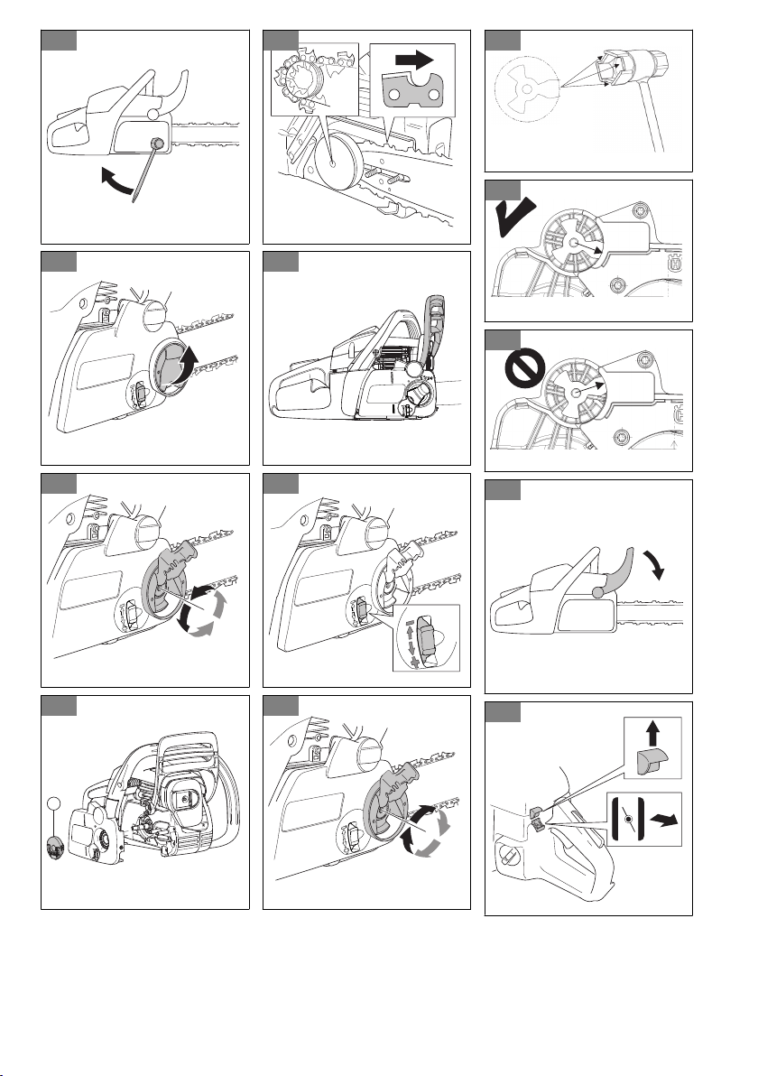
2. Remove the bar nuts and the clutch cover. Remove
the transportation guard (A). (Fig. 39)
3. Put the guide bar on the bar bolts and push the
guide bar to its most rear position. (Fig. 40)
4. Lift the saw chain above the drive sprocket and
engage it in the groove on the guide bar. Start on
the top edge of the guide bar. (Fig. 41)
5. Make sure that the edges of the cutting links are
turned forward on the top edge of the guide bar.
6. Install the clutch cover and steer the chain adjuster
pin to the hole in the guide bar.
7. Make sure that the drive links of the saw chain fit
correctly on the drive sprocket. Also make sure that
the saw chain is correctly engaged in the groove in
the guide bar.
8. Tighten the guide bar nuts with your fingers.
9. Tighten the saw chain by turning the chain
tensioning screw clockwise with the combination
wrench (Fig. 42). Tighten the saw chain until it does
not sag from below the guide bar, but you can turn it
easily by hand. (Fig. 43)
10. Hold up the end of the guide bar and tighten the bar
nuts with the combination wrench. (Fig. 44)
• Examine the chain tension frequently after you
assemble a new saw chain and until the saw
chain has been run-in.
• Examine the chain tension regularly. Correct
chain tension results in good cutting performance
and a long life.
To assemble the guide bar and the
saw chain (knob and wheel chain
adjustment)
WARNING:
Use protective gloves
when you assemble the guide bar and the
saw chain.
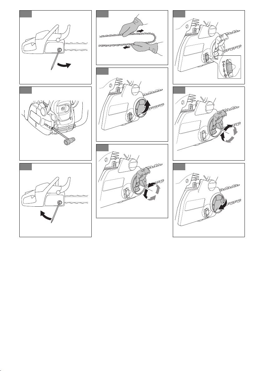
1. Move the front hand guard in the direction of the
front handle to disengage the chain brake.
2. Fold the knob out to open position. (Fig. 45)
3. Turn the knob counterclockwise to loosen the clutch
cover. (Fig. 46)
4. Remove the knob (A) and the clutch cover. Remove
the transportation guard, if it is installed. (Fig. 47)
5. Put the guide bar over the bar bolts and push the
guide bar to its most rear position. Put the chain over
the drive sprocket and engage it in the groove on the
guide bar. Start on the top edge of the guide bar.
(Fig. 48)
6. Make sure that the edges of the cutting links are
turned forward on the top edge of the guide bar.
7. Install the clutch cover and steer the chain adjuster
pin to the hole in the guide bar. Make sure that
the drive links of the chain fit correctly on the drive
sprocket. Also make sure that the saw chain is
correctly engaged in the groove in the guide bar.
(Fig. 49)
8. Tighten the saw chain by turning the wheel down (+).
Tighten the chain until it does not sag from below of
the guide bar. (Fig. 50)
9. The saw chain is correctly tightened when it does not
sag from below the guide bar, but you can turn the
saw chain easily by hand.
10. Hold up the guide bar tip and turn the knob
clockwise to tighten it. (Fig. 51)
• Examine the chain tension frequently after you
assemble a new saw chain and until the saw
chain has been run-in.
• Examine the chain tension regularly. Correct
chain tension results in good cutting performance
and a long life.
To reset the chain brake
If the clutch cover is removed accidentally while the
chain brake is locked, the chain brake must be unlocked
so the clutch cover can be assembled without binding to
the clutch drum.
CAUTION:
The chain brake spring is
under tension. Use care when resetting the
chain brake.
Note: Do not hold the brake band while attempting to
reset it.
1. Align the notches on the bar tool so that they fit over
the brake rotating link. (Fig. 52)
653 - 010 - 10.07.2023
13
2. To reset the brake, rotate the link clockwise until it
stops. The front link will be in its downward rotated
position when the chain brake is unlocked. (Fig. 53)
(Fig. 54)
Operation
WARNING: Read and understand the
safety chapter before you operate the
product.
To use fuel
CAUTION: This product has a two-
stroke engine. Use a mixture of gasoline
and two-stroke engine oil. Make sure to use
the correct quantity of oil in the mixture.
Incorrect ratio of gasoline and oil can cause
damage to the engine.
Fuel mixture ratio
The fuel mixture ratio for the gasoline and two-cycle
engine oil is 50:1 (2%)
Gasoline
Two-cycle engine oil
1 U.S. Gal. 77 ml (2.6 oz)
1 UK Gal. 95 ml (3.2 oz)
5 l 100 ml (3.4 oz)
To make the fuel mixture
1. Determine the correct quantity of gasoline and
engine oil (mixture ratio 50:1). Do not make more
than 30 days quantity of fuel mixture. See
Fuel
mixture ratio on page 14
.
2. Add half of the gasoline quantity to a clean fuel
container with an antispill valve.
CAUTION:
Do not use gasoline with
more than 10% ethanol concentration
(E10). This can cause damage to the
product.
CAUTION: Do not use gasoline with
an octane number less than 90 RON
(87 AKI). This can cause damage to the
product.
Note: Use gasoline with a higher octane number if
you frequently use the product at continuously high
engine speed.
3. Add the full quantity of the two-cycle engine oil to the
fuel container.
CAUTION:
Always use air-cooled
two-cycled engine oil of high quality.
Other oils can cause damage to the
product.
4. Shake the fuel mixture to mix the contents.
5. Add the remaining gasoline quantity to the fuel
container.
6. Shake the fuel mixture to mix the contents.
7. Fill the fuel tank of the product with the fuel mixture.
See
To fill the fuel tank on page 14
.
To fill the fuel tank
1. Make sure that the fuel mixture is correct and that
the fuel mixture is in a fuel container with an antispill
valve.
2. If fuel is on the container, remove the unwanted fuel
and let the container dry.
3. Make sure that the area near the fuel tank cap is
clean.
4. Remove the fuel tank cap.
5. Shake the fuel container before you add the fuel
mixture to the fuel tank.
6. Put back the fuel tank cap.
To lubricate the saw chain
The product has an automatic lubrication system. The
saw chain oil tank and the fuel tank are designed so that
the fuel runs out before the saw chain oil. This safety
feature requires that the correct chain oil is used and
that the instructions are obeyed.
1. Use vegetable-based saw chain oil or a standard
chain oil.
2. Make sure that the area near the cap of the saw
chain oil tank is clean.
3. Remove the cap of the saw chain oil tank.
4. Fill the saw chain oil tank with the recommended
saw chain oil.
5. Put back the cap of the saw chain oil tank.
To start and stop
Before you start the engine
• Examine the product for missing, damaged, loose or
worn parts.
• Examine the nuts, screws and bolts.
• Examine the air filter.
14
653 - 010 - 10.07.2023

• Examine the trigger lockout and the trigger for
correct operation.
• Examine the stop switch for correct operation.
• Examine the product for fuel leaks.
• Examine the saw chain sharpness and tension.
To start a cold engine
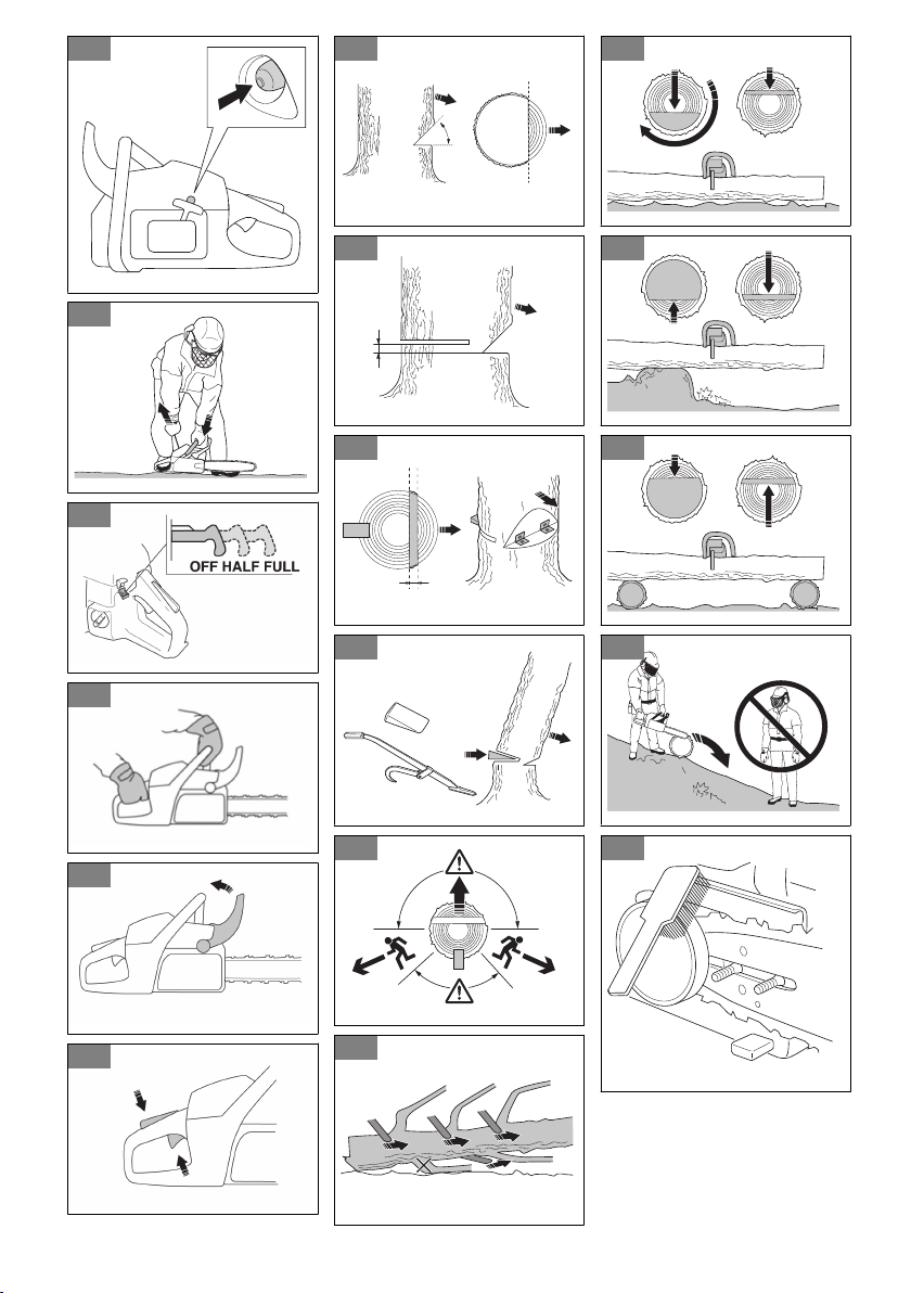
1. Move the front hand guard forward to engage the
chain brake. (Fig. 55)
2. Pull the choke control out fully. (Fig. 56)
3. Push the air purge bulb 6 times. (Fig. 57)
4. Hold the body of the product on the ground with your
left hand.
5. Put your right foot through the rear handle.
6. Pull the starter rope handle slowly with your right
hand until you feel some resistance.
7. Pull the starter rope handle with force. (Fig. 58)
CAUTION: Do not pull the starter
rope until it stops. Do not let go of the
starter rope when it is fully extended.
Release the starter rope slowly. If you do
not obey these instructions, it can cause
damage to the engine.
Note: Do not pull the throttle trigger when you start
the engine.
8. Continue to pull the starter rope handle until the
engine starts or tries to start (pull max 5 times).
9. If the engine starts or tries to start, push the choke
control in to the half choke position. (Fig. 59)
10. Continue to pull until the engine starts.
11. Hold the rear handle with your right hand and the
front handle with your left hand. (Fig. 60)
12. Immediately pull the front hand guard rearward in the
direction of the front handle to disengage the chain
brake. (Fig. 61)
Note:
The chain will move.
13. Run 20-30 seconds at elevated idle speed.
14. Pull the throttle trigger slowly but fully for 8-10
seconds, then release. (Fig. 62)
15. Run 10 seconds at normal idle speed.
16. Pull the throttle trigger slowly but fully for 5 seconds
to check acceleration, then release.
17. Use the product.
To start a warm engine
1. Move the front hand guard forward to engage the
chain brake.
2. Pull the choke control out fully.
3. Push the air purge bulb 6 times.
4. Push the choke control in fully.
5. Hold the body of the product on the ground with your
left hand.
6. Put your right foot through the rear handle.
7. Pull the starter rope handle slowly with your right
hand until you feel some resistance.
8. Pull the starter rope handle with force.
CAUTION: Do not pull the starter
rope until it stops. Do not let go of the
starter rope when it is fully extended.
Release the starter rope slowly. If you do
not obey these instructions, it can cause
damage to the engine.
Note: Do not pull the throttle trigger when you start
the engine.
9. Pull the starter rope handle until the engine starts.
10. Hold the rear handle with your right hand and the
front handle with your left hand.
11. Immediately pull the front hand guard rearward in the
direction of the front handle to disengage the chain
brake.
Note: The chain will move.
12. Wait 10-15 seconds.
13. Pull the throttle trigger lightly to set normal idle.
14. Use the product.
To start the engine when the fuel is too hot
If the product does not start, the fuel can be too hot.
Note:
Always use new fuel and decrease the
operation time during warm weather.
1. Put the product in a cool area away from open
sunlight.
2. Let the product cool down for 20 minutes at
minimum.
3. Press the air purge bulb again and again for 10-15
seconds.
4. Obey the procedure to start a cold engine. Refer to
To start a cold engine on page 15
.
To stop the engine
• Push the stop switch to stop the engine.
Note:
The stop switch automatically goes back to its
initial position.
653 - 010 - 10.07.2023 15

To fell a tree
1. Remove dirt, stones, loose bark, nails, staples and
wire from the tree.
2. Make a notch 1/3 the diameter of the tree,
perpendicular to the direction of the fall. (Fig. 63)
3. Make the lower horizontal notch cut. This will prevent
either the saw chain or the guide bar from being
pinched when the second notch is made.
4. Make the felling back cut (X) at least 50 mm (2 in)
higher than the horizontal notching cut. Keep the
felling back cut parallel to the horizontal notching cut
so enough wood is left to act as a hinge. Do not cut
through the hinge. The hinge wood keeps the tree
from twisting and falling in the wrong direction. (Fig.
64) (Fig. 65)
5. As the felling back cut nears the hinge, the tree
starts to fall. Make sure that the tree can fall in the
correct direction and not rock rearward and pinch the
saw chain. Stop the cut before the felling back cut
is complete to prevent this. Use wedges of wood,
plastic or aluminium to open the cut and let the tree
fall along the necessary line of fall. (Fig. 66)
6. When the tree begins to fall, remove the product
from the cut, stop the engine, put the product down,
then use the retreat path planned. Be alert for
overhead limbs falling and watch your footing. (Fig.
67)
To limb a tree
1. Use larger limbs to hold the log off the ground.
2. Remove small limbs in one cut. (Fig. 68)
3. Cut branches that have tension from the bottom to
the top to prevent pinching the saw chain or the
guide bar.
To buck a log
CAUTION: Do not let the saw chain
touch the ground.
• If the log is supported along its entire length, cut
from the top of the log (known as overbucking). (Fig.
69)
• If the log is supported on one end, cut 1/3 the
diameter from the underside of the log (known as
underbucking) . (Fig. 70)
• If the log is supported on both ends, cut 1/3
the diameter from the top. Complete the cut by
underbucking the lower 2/3 of the log to meet the
first cut. (Fig. 71)
• If you buck a log on a slope, always stand on the
uphill side of the log. Cut through the log while
you maintain complete control of the product, then
release the cutting pressure near the end of the
cut while firmly gripping the rear handle and front
handle. (Fig. 72)
Maintenance
WARNING: Read and understand the
safety chapter before you clean, repair or do
maintenance on the product.
Maintenance schedule
Make sure that you obey the maintenance schedule.
The intervals are calculated from daily use of the
product. The intervals are different if you do not use the
product each day. Only do the maintenance work that
is found in this manual. Speak to an approved service
center about other maintenance work not found in this
manual.
Daily maintenance
• Clean the external surfaces.
• Make sure that the lockout and trigger work
correctly.
• Clean the chain brake and make sure that it works
correctly.
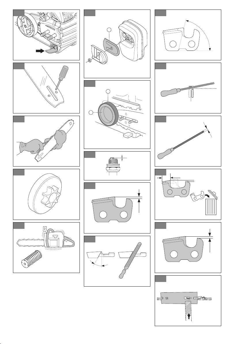
(Fig. 73)
• Examine the chain catcher for damage. Replace the
chain catcher if it is damaged.
(Fig. 74)
• Turn the guide bar daily for more even wear.
• Make sure that the lubrication hole in the guide bar is
not clogged.
(Fig. 75)
• Clean the guide bar groove.
(Fig. 76)
• Make sure that the guide bar and saw chain get
sufficient oil.
• Examine the saw chain:
• for cracks in the rivets and links.
• for abnormally worn rivets and links.
• for correct tension.
If necessary, replace the saw chain.
• Sharpen the saw chain. See
To sharpen the saw
chain on page 18
.
• Examine the drive sprocket for excessive wear and
replace if necessary.
(Fig. 77)
• Clean the air intake of the starter unit.
• Make sure that the nuts and screws are tight.
16 653 - 010 - 10.07.2023

• Make sure that the stop switch works correctly.
• Examine the engine, tank and fuel lines for fuel
leaks.
• Make sure that the saw chain does not rotate when
the engine is idling.
Weekly maintenance
• Make sure that the cooling system works correctly.
• Make sure that the starter, starter cord and return
spring work correctly.
• Make sure that the vibration damping elements are
not damaged.
(Fig. 78)
• File off any burrs from the edges of the guide bar.
• Clean or replace the spark arrestor screen on the
muffler.
(Fig. 79)
• Clean the external surfaces of the carburetor and its
adjacent areas.
• Clean the air filter. Install a new air filter if it is
damaged or too dirty to be fully cleaned. See
To
clean the air filter on page 17
for more information.
Monthly maintenance
• Examine the brake band on the chain brake for
wear. Replace when the brake band thickness is
less than 0.6 mm (0.024 in) at the most worn point.
(Fig. 80)
• Examine the clutch center, clutch drum and clutch
spring for wear.
• Clean the spark plug. Make sure that the electrode
gap is correct.
(Fig. 81)
• Clean the external surfaces of the carburetor and its
adjacent areas.
• Examine the fuel filter and the fuel hose. Replace if
necessary.
• Empty the fuel tank.
• Empty the oil tank.
• Examine all cables and connections.
Yearly maintenance
• Examine the spark plug.
• Clean the external surfaces of the carburetor and its
adjacent areas.
• Clean the cooling system.
• Examine the spark arrester mesh.
• Examine the fuel filter.
• Examine the fuel hose for damage.
• Examine all cables and connections.
Intermittent maintenance
• Have an approved service center repair or replace
the muffler after 50 hours of operation.
• Do maintenance on the spark plug when:
• the power level in the engine is low.
• it is hard to start the engine.
• the engine does not work correctly at idle speed.
• Do a check of the saw chain lubrication each time
you refuel. See
To do a check of the saw chain
lubrication on page 19
.
To adjust the idle speed
Make sure that the air filter is clean and the air filter
cover is attached before you adjust the idle speed.
1. Turn the idle adjustment screw, which is identified
with a "T" mark, clockwise until the saw chain starts
to turn.
2. Turn the idle adjustment screw, which is identified
with a "T" mark, counterclockwise until the saw chain
stops.
3. The idle speed must be below the speed when the
saw chain starts to turn. The idle speed is correct
when the engine operates smoothly in all positions.
To clean the spark arrester screen
1. Use a wire brush to clean the spark arrester screen.
To do maintenance on the spark plug
CAUTION: Use the recommended
spark plug. Make sure that the replacement
is the same as the manufacturer supplied
part. An incorrect spark plug can cause
damage to the product.
1. If the product is hard to start or operate, examine
the spark plug for unwanted materials. To decrease
the risk of unwanted material on the spark plug
electrodes:
a) make sure that the idle speed is correctly
adjusted.
b) make sure that the fuel mixture is correct.
c) make sure that the air filter is clean.
2. Clean the spark plug if it is dirty. Make sure that the
electrode gap is correct. (Fig. 81)
3. Replace the spark plug when it is necessary.
To clean the air filter
1. Remove the air filter cover and remove the air filter.
2. Clean the air filter with warm soap water. Make sure
that the air filter is dry before you install it.
3. Replace the air filter if it is too dirty to fully clean it.
Always replace a damaged air filter.
653 - 010 - 10.07.2023
17

To sharpen the saw chain
The cutter
The cutting part of the saw chain is called the cutter and
consists of a cutting tooth (A) and the depth gauge (B).
The cutters cutting depth is determined by the difference
in height between the two, the depth gauge setting (C).
(Fig. 82)
When you sharpen a cutting tooth there are four
important factors to remember:
• Filing angle.
(Fig. 83)
• Cutting angle.
(Fig. 84)
• File position.
(Fig. 85)
• Round file diameter.
(Fig. 86)
To sharpen the cutting teeth
Use a round file and a file gauge to sharpen the cutting
teeth. See
Saw chain filing and saw chain combinations
on page 21
for information on the recommended
dimension of the file and gauge for the saw chain
installed on your product.
1. Make sure that the saw chain is correctly tensioned.
A slack chain will move sideways, making it more
difficult to sharpen correctly.
2. File all teeth on one side first. File the cutting teeth
from the inside face and reduce the pressure on the
return stroke.
3. Turn the product over and file the teeth on the other
side.
4. File all the teeth to the same length. When the length
of the cutting teeth is reduced to 4 mm (5/32") the
saw chain is worn out and must be replaced. (Fig.
87)
To adjust the depth gauge setting
Sharpen the cutting teeth before you adjust the depth
gauge setting. See
To sharpen the cutting teeth on page
18
. When you sharpen the cutting tooth (A), the depth
gauge setting (C) will decrease. To maintain optimal
cutting performance, the depth gauge (B) has to be filed
down to achieve the recommended depth gauge setting.
See
Saw chain filing and saw chain combinations on
page 21
to find the correct depth gauge setting for your
particular chain.
(Fig. 88)
(Fig. 89)
Note:
This recommendation assumes that the length
of the cutting teeth is not reduced excessively.
Use a flat file and depth gauge tool to adjust the depth
gauge.
1. Put the depth gauge tool above the saw chain.
Detailed information regarding how to use the depth
gauge tool will be found on the package of the depth
gauge tool.
2. Use the flat file to file off the tip of the depth gauge
that protrudes through the depth gauge tool. The
depth gauge setting is correct when you no longer
feel resistance as you draw the file along the depth
gauge tool.
To tension the saw chain (standard chain
adjustment)
Note: Check the tension of a new saw chain
frequently during its running-in period.
1. Loosen the guide bar nuts that hold the clutch cover.
Use the combination wrench. (Fig. 90)
2. Tighten the guide bar nuts by hand as tight as you
can.
3. Lift the top of the guide bar and extend the saw
chain by tightening the chain tensioning screw. Use
the combination wrench. Tighten the saw chain until
it does not hang down from the bottom of the guide
bar. (Fig. 91)
4. Tighten the guide bar nuts using the combination
wrench and lift the tip of the guide bar at the same
time. (Fig. 92)
5. Make sure that you can pull the saw chain round
freely by hand and that it does not sag. (Fig. 93)
To tension the saw chain (knob and wheel
chain adjustment)
Note:
Examine the tension of a new saw chain
frequently during its running-in period.
1. Release the knob by folding it out. (Fig. 94)
2. Turn the knob counterclockwise to loosen the clutch
cover. (Fig. 95)
3. Adjust the tension on the chain by turning the chain
tensioner wheel down (+) for tighter tension and up
(-) to loosen the tension. Hold the tip of the guide bar
while you adjust the tension. (Fig. 96)
4. Tighten the clutch cover by turning the knob
clockwise while lifting the tip of the guide bar. (Fig.
97)
5. Fold the knob in to lock the saw chain. (Fig. 98)
6. Make sure that you can pull the saw chain round
freely by hand and that it does not sag. (Fig. 93)
18
653 - 010 - 10.07.2023

To lubricate the cutting equipment
To do a check of the saw chain lubrication
Do a check of the chain saw lubrication each time you
refuel.
1. Start the product and let it run at 3/4 speed. Point the
nose of the guide bar at a light color surface almost
20 cm (8 in) away.
2. After 1 minute of running, a line of oil shows on the
light surface.
3. If you cannot see the line of oil after 1 minute, clean
the oil channel in the guide bar. Clean the groove
in the edge of the guide bar. Make sure the guide
bar nose sprocket turns freely and that there are no
blockages in the lubrication hole. Clean and lubricate
the tip sprocket.
4. Start the product and let it run at 3/4 speed. Point the
nose of the bar at a light color surface almost 20 cm
(8 in) away.
5. After 1 minute of running, a line of oil shows on the
light surface.
6. If you cannot see the line of oil after 1 minute, speak
to your approved dealer.
Transportation
• Put the transportation guard on the cutting
attachment during transportation to prevent injuries.
• Make sure that the product can not move during
transportation.
Storage
• Always put the product away safely when not in
operation. Leakages and fumes from the product
can touch sparks, naked flames from electrical
equipment, electrical mowers, relays/switches,
boilers and more.
• Always save fuel in an approved container.
• Empty the fuel tank and the chain oil tank when
the product is in storage for longer periods of time.
Discard used fluids correctly.
• Put the transportation guard on the cutting
attachment during storage to prevent injuries.
• Remove the spark plug cap from the spark plug and
engage the chain brake before storage.
Technical data
unit
120e Mark II
(P02138HV)
Engine specifications
Cylinder displacement cm
3
38
Spark plug
Champion RCJ7Y,
BRISK HQT-1R
Electrode gap mm (in) 0,5 (0.02)
Fuel tank volume cm
3
300
Idle speed min
-1
2800-3200
Power output at 9000 min
-1
kW 1,4
Emission durability period h 125
Noise and vibration data
653 - 010 - 10.07.2023 19

unit
120e Mark II
(P02138HV)
Equivalent vibration levels, a
hveq
front handle
1
m/s
2
5,3
Equivalent vibration levels, a
hveq
rear handle
2
m/s
2
6,7
Sound power level, guaranteed (L
WA
)
3
dB(A) 116
Sound power level, measured
4
dB(A) 113
Sound pressure level at operator's ear
5
dB(A) 100
Product dimensions
Weight (excluding cutting equipment) kg (lb) 5,0 (11,0)
Oil tank volume cm
3
200
Fuel and lubrication system
Oil pump capacity at 9000 min
-1
ml/min 7
Type of oil pump Automatic
Saw chain and guide bar
Standard guide bar length cm (in) 35-40 (14-16)
Recommended bar lengths cm (in) 33-46 (13-18 )
Usable cutting length cm (in) 29-43 (11-17)
Maximum saw chain speed m/s 26,1
Saw chain pitch mm (in) 8,3 (0.325) 9,52 (3/8)
Thickness of drive links (gauge) mm (in) 1,3 (0.05)
Type of drive sprocket 0,325 and 3/8
Number of drive sprocket teeth
6 (drive sprocket
3/8), 7 (drive sprock-
et 0,325)
Accessories
Guide bar and saw chain combinations
The cutting attachments below are approved for the
product.
1
Equivalent vibration level, according to ISO 22867, is calculated as the time-weighted energy total for vibration
levels under various working conditions. Reported data for equivalent vibration level has a typical statistical
dispersion (standard deviation) of 1 m/s
2
.
2
Equivalent vibration level, according to ISO 22867, is calculated as the time-weighted energy total for vibration
levels under various working conditions. Reported data for equivalent vibration level has a typical statistical
dispersion (standard deviation) of 1 m/s
2
.
3
Noise emissions in the environment measured as sound power (L
WA
).
4
Noise emissions in the environment measured as sound power (L
WA
).
5
Equivalent sound pressure level is calculated as the time-weighted energy total for different sound pressure
levels under various working conditions. Typical statistical dispersion for equivalent sound pressure level is a
standard deviation of 1 dB(A).
20 653 - 010 - 10.07.2023
Guide bar Saw chain
Length, cm (in) Pitch, mm (in) Gauge, mm (in) Max. nose radius Type Drive link count
35 (14) 9,52 (3/8) 1,3 (0,050) 7T Husqvarna S93G
Husqvarna H37
52
40 (16) 9,52 (3/8) 56
45 (18) 9,52 (3/8) 62
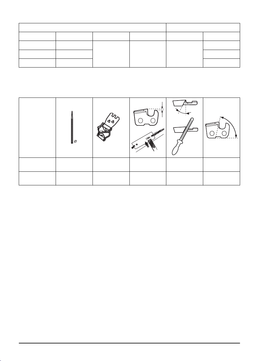
Saw chain filing and saw chain combinations
H37 5/32 in / 4.0 mm 579 65 36-01
0.025 in / 0.65
mm
30° 80°
S93G 5/32 in / 4.0 mm 587 80 90-01 0.025 in / 0.65
mm
30° 60°
653 - 010 - 10.07.2023 21

22 653 - 010 - 10.07.2023

653 - 010 - 10.07.2023 23

www.husqvarna.com
Original instructions
1143721-26
2023-07-13