[RuFTS
MODEL NUMBER 917.258540
®
OWNER'S MANUAL
=Assembly
®Operation
° Customer Responsibilities
• Service and Adjustments
° Repair Parts
CAUTION: Read and follow all safety rules and instructions before operating this equipment.
FOR CONSUMER ASSISTANCE HOT LINE, CALLTHIS TOLL FREE NUMBER: 1-800-659-5917
SAFETY RULES
Safe Operation Practices for Ride-On Mowers
IMPORTANT: THIS CUTTING MACHINE IS CAPABLE OF AMPUTATING HANDS AND FEET AND THROWING OBJECTS_
FAILURE TO OBSERVE THE FOLLOWING SAFETY INSTRUCTIONS COULD RESULT IN SERIOUS INJURY OR DEATH°
t. GENERAL OPERATION
• Read, understand, and foUowall instructionsin the manL_l
and on the machine before starting.
= Only allow responsible adults, who are familiar with the
instructions, to operate the machine_
• Clear the area of objects such as rocks, toys, wire, etc.,
which could be picked up and thrown bythe blade_
° Besuretheareaisclearofotherpeoptebeforemowingo Stop
machine if anyone enters the area.
= Never carry passengers.
• Do not mow inreverse unlessabsolutely necessary., Always
look down and behind before and while backing
• Be aware of the mower discharge directionand do not point
it at anyone_ Do not operate the mower without either the
entire grass catcher or the guard in place.,
• Slow down before turning,
• Never leave a running machine unattended. Always turn off
blades, set parking brake, stop engine, and remove keys
before dismounting.
• Turn off blades when not mowing.
• Stop engine before removing grass catcher or unclogging
chute.
• Mow only in daylight or good artificial lighL
• Do not operate the machine while under the influence of
alcohol or drugs.
• Watch for trafficwhen operating near orcrossing roadways,
• Use extra care when loading or unloadingthe machine into
a trailer or truck.,
Ii. SLOPE OPERATION
Slopes are a major factor related to loss-of-control and
tipover accidents, which can result in severe injury or death.
All slopes require extra caution, tf you cannot back up the
slope or if you feel uneasy on it, do not mow it.
DO:
• Mow up and down slopes, not across_
• Remove obstacles such as rocks, tree limbs, etc_
° Watch for holes, ruts, or bumps. Uneven terrain could
overturn the machine_ Taft grass can hide obstac/es,
• Use slow speed Choose a lowgear so that youwiltnot have
to stop or shift while on the slope.
• Follow the manufacturer's recommendations for wheel
weights or counterweights to improve stabUity,
• Use extra care with grass catchers or other attachments_
These can change the stabilityof the machine.
• Keep all movement on the slopes s/ow and gradual. Do not
make sudden changes in speed or direction_
= Avoid starting or stopping on a slope, if tires lose traction,
disengage the blades and proceed slowly straight down the
slope_
DO NOT:
° Do not turnon slopes unlessnecessary, and then,turn slowly
and gradually downhill, if posstble_
• Do not mow near drop-offs,ditches, or embankments_ The
mower could suddenly turn over if a wheel is over the edge
of a cliff or ditch, or if an edge caves in
° Do not mow on wet grass, Reduced traction could cause
sliding.
° Do not tryto stabilize the machine by puttingyour foot on the
ground.
° Do not use grass catcher on steep slopes°
2
I!!. CHILDREN
Tragic accidents can occur if the operator' is not alert to the
presence of children. Children are often attracted to the
machine and the mowing activity, Never assume that
children will remain where you last saw them,
• Keep children outof the mowing area and under the watchful
care of another responsible adult.
• Be alert and turn machine off if children enter the area°
• Before and when backing, look behind and down for small
children.
• Never carry children. They may fall off and be seriously
injured or interfere with safe machine operation_
° Never allow children to operate the machine_
• Use extra care when approaching blind comers, shrubs,
trees, or other objects that may obscure vision.,
IV. SERVICE
° Use extra care i_nhandlinggasoline and other fuels..They are
flammable and vapors are explosive_
Use only an approved container_
Never remove gas cap or add fuel with the engine
running. Allow engine to cool before refueling.. Do not
smoke,
Never refuel the machine indoors.
Never store the machine or fuel container inside where
there is an open flame, such as a water heater.
° Never run a machine inside a closed area.
° Keep nuts and bolts, especially blade attachment bolts, tight
and keep equipment in good condition_
° Never tamper with safety devices. Check their proper
operation regularly.
• Keep machine free of grass, leaves, or other debris build-up.
Clean oil or fuel spiUageo Allow machine to cool before
storing..
• Stop and inspect the equipment if you strike an object.
Repair, if necessary, before restarting
• Never make adjustments or repairs with the engine running.
, Grass catchercomponents are subject to wear, damage, and
deterioration, which could expose moving parts or aflow
objects to be thrown. Frequently check components and
replace with manufacturer s recommended parts, when nero
essary.
° Mower blades are sharp and can cut.. Wrap the blade(s) or
wear gloves, and use extra caution when servicing them
• Check brake operation frequently_ Adjust and service as
required_
Look for this sy'mbol to P'oin'i'"'OUtira-'"'t
portant safety precautions. It means I
CAUTIONI!I BECOMEALERTt!t YOUR I
SAFETY IS INVOLVED. I
i illl ill l , iilll ...........................
I ..................................................I
CAUTION: Always disconnect spark plug
wire and place wire where it cannot contact
spark plug tn order to prevent accidental
starting when setting up, transporting,
! adjusting or making repairs. ............
II I II1'1 1,1,1,I iiiiii , I,,H!,II,II,I, I I II1' IIII I
WARNING &
The engine exhaust from this product con-
tains ctiemicals known to the State of Califor-
nia to cause cancer, birth defects, or other
reproductive harm.
............................. ii ii L
CONGRATULATIONS on your purchase of a Sears
Tractor. It has been designed, engineered and manufac-
tured to give you the best possible dependability and
performance.
Should you experience any problem you cannot easily
remedy, please contact your nearest Sears Authorized
Service CentedDepartmenL We have competent, well-
trained techniciansand the proper tools to service or repair
this tractor_
Please read and retain this manual. The instructions will
enable you to assemble and maintain your tractor properly.
Always observe the "SAFETY RULES".
MODEL
NUMBER 917.258540
SERIAL
NUMBER
DATE OF PURCHASE
THE MODEL AND SERIAL NUMBERS WILL BE FOUND
ON A PLATE UNDER THE SEAT.
YOU SHOULD RECORD BOTH SERIAL NUMBER AND
DATE OF PURCHASE AND KEEP IN A SAFE PLACE
FOR FUTURE REFERENCE.
MAINTENANCE AGREEMENT
A Sears Maintenance Agreement is available on this prod-
uct. Contact your nearest Sears store for details.
CUSTOMER RESPONSIBILITIES
• Read and observe the safety rules.
, Followaregularschedulein maintaining, caringforand
using your tractor.
o Follow the instructions under"Customer Responsibili-
ties" and "Storage" sections of this owner's manual
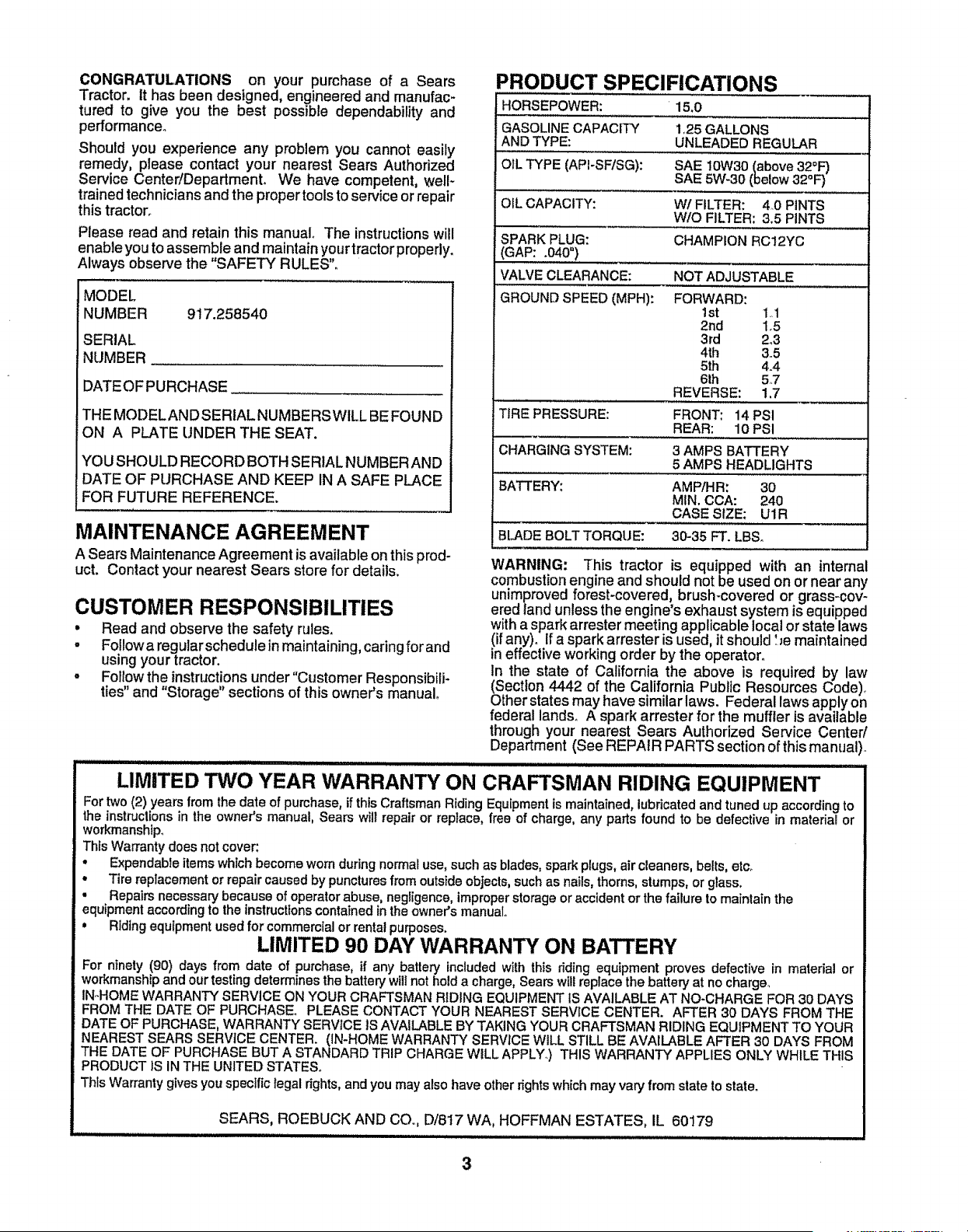
PRODUCT SPECIFICATIONS
HORSEPOWER: 15.0
GASOLINE CAPACITY 1.25 GALLONS
AND TYPE: UNLEADED REGULAR
OIL TYPE (API-SF/SG): SAE 10W30 (above 32=1=)
SAE 5W-30 (below 32°1=)
OIL CAPACITY: W/FILTER: 4_0 PINTS
W/O FILTER: 3.5 PINTS
SPARK PLUG: CHAMPION RC12YC
(GAP: .040 °)
VALVE CLEARANCE: NOT ADJUSTABLE
GROUND SPEED (MPH): FORWARD:
1st 1.1
2rid 1o5
3rd 2°3
4th 3.5
5th 4.4
6th 5.7
REVERSE: 1,7
TIRE PRESSURE: FRONT: 14 PSI
REAR: 10 PSI
CHARGING SYSTEM: 3 AMPS BATTERY
5 AMPS HEADLIGHTS
BATTERY: AMP/HR: 30
MIN. CCA: 240
CASE SIZE: U1R
BLADE BOLT TORQUE: 30-35 FT. LBS.
WARNING: This tractor is equipped with an internal
combustion engine and should not be used on or near any
unimproved forest-covered, brush-covered or grass-cov-
ered land unless the engine's exhaust system is equipped
with a spark arrester meeting applicable local or state laws
(if any). If a spark arrester is used, it should '.._emaintained
in effective working order by the operator.
In the state of California the above is required by law
(Section 4442 of the California Public Resources Code)_
Other states may have similar laws. Federal laws apply on
federal lands° A spark arrester for the muffler is available
through your nearest Sears Authorized Service Center/
Department (See REPAIR PARTS section of this manual)_
LIMITED TWO YEAR WARRANTY ON CRAFTSMAN RIDING EQUIPMENT
For two (2) years from the date of pumhase, if this Craftsman Riding Equipmentis maintained, lubricated and tuned up according to
the instructions in the owner's manual, Sears will repair or replace, free of charge, any parts found to be defective in material or
workmanship.
Thls Warranty does not cover:
° Expendable items whtch become worn during normal use, such as blades, spark plugs, air cleaners, belts, etco
° Tire replacement or repair caused by puncturesfrom outside objects, such as nails, thorns, stumps, or glass.
° Repairs necessary because of operator abuse, negligence, improper storage or accident or the failure to maintain the
equipment according to the instructions contained in the owner's manual
, Riding equipment used for commercial or rental purposes.
LIMITED 90 DAY WARRANTY ON BATTERY
For ninety (90) days from date of purchase, if any battery included with this riding equipment proves defective in material or
workmanship and our testing determines the battery will not hold a charge, Sears witl replace the battery at no charge_
IN-HOME WARRANTY SERVICE ON YOUR CRAFTSMAN RIDING EQUIPMENT IS AVAILABLE AT NO-CHARGE FOR 30 DAYS
FROM THE DATE OF PURCHASE. PLEASE CONTACT YOUR NEAREST SERVICE CENTER. AFTER 30 DAYS FROM THE
DATE OF PURCHASE, WARRANTY SERVICE tS AVAILABLE BY TAKING YOUR CRAFTSMAN RIDING EQUIPMENT TO YOUR
NEAREST SEARS SERVICE CENTER. (1N-HOME WARRANTY SERVICE WiLL STILL BE AVAILABLE AFTER 30 DAYS FROM
THE DATE OF PURCHASE BUT A STANDARD TRIP CHARGE WILL APPLY.) THIS WARRANTY APPLIES ONLY WHILE THIS
PRODUCT 1S IN THE UNITED STATES.
This Warranty gives you specific legal dghts, and you may also have other rights which may vary from state to state.
SEARS, ROEBUCK AND CO.., D/817 WA, HOFFMAN ESTATES, IL 60179
,,,,, ............................................................... ,...........................................
3

TABLE OF CONTENTS
SAFETY RULES ............................................................ 2
PRODUCT SPECIFICATIONS ...................................... 3
CUSTOMER RESPONSIBILITIES ..................... 3, 15-19
WARRANTY .................................................................. 3
TABLE OF CONTENTS ........................................... +,_..4
ASSEMBLY ................................................................ 7*9
OPERATION ........................................................... 10-14
MAINTENANCE SCHEDULE ...................................... 15
SERVICE AND ADJUSTMENTS ............................ 20-25
STORAGE ................................................................... 26
TROUBLESHOOTING ............................................ 27+28
REPAIR PARTS - TRACTOR ................................. 30.47
REPAIR PARTS - ENGINE .................................... 48-53
PARTS ORDERING/SERVICE .................. BACK PAGE
iNDEX
A
Accessories ............................................................5
Adjustments:
Brake ........................................................22
Carburetor ..............................................25
Mower:
Front-To-Back .............................21
Side.To+Side ............................ 21
Throttle Control Cable .....................25
Air Filter, Engine .......................................18
Air Screen, Engine ...................................18
Assembly.............................................................7-9
B
Battery:
Charging .......................................................7
Cleaning ......................................... 16
Starting with Weak Battery ...........23
Storage .......................................... 26
Terminals ..........................................16
Bolls:
Motion Drive
Removal/Replacement .......... 22
Mower Blade Drive
Removal!Replacement ............22
Blade:
Sharpening ...........................................16
Replacement ..........................................16
Brake Adjustment .........................................22
C
Carburetor Adjustment ...........................25
Controls, Tractor .....................................11
Customer Responsibilities ................15-19
Engine:
Air Filter ...................................... 18
Air Screen, Engine ................... 18
Battery .........................................17
Cooling Fins, Engine ...................t8
Engine Oil .............................................17
Fuel Filter........................................19
Spark Plugs .....................................18
Tractor:
Blades ..........................................16
Lubrication Chart ...................... 15
Maintenance Schedule .............15
Tire Care ...................................9,16,23
Cutting Height, Mower ............................12
E
Electrical:
Interlocks and Relays ........................24
Schematic ..............................................29
Wiring Diagram ....................................30
Engine:
Air Fitter .................................................18
Air Screen ........................................18
Cooling Fins, Engine .................... 18
Oil Change .............................................17
Oil Level ...........................................13,17
Oil Type ......;............._...............................17
Preparation ........................................13
Repair Parts .................................48-53
Starting............................................14
Storage ............................................26
F
Filters:
Air ......................................................................18
Fuel ...................................................................19
Fuel:
Type .....................................................13
Storage ................................................26
Fuse ..............................................................24
G
Gauge Wheels ....................................................8
H
Hood Removal/Installation .....................24
L
Leveling Mower Deck ..............................2t
LubricationChart ..............................................15
M
Maintenance Schedule ............................15
Mower:
Adjustment, Front-to+Back ................21
Adjustment, S+de+to-Side..............2I
Blade Sharpening
..........................
......
16
Blade Replacement ..................... 16
Cutting Height
......................................
12
Installation..............................................20
Operation ............................................................13
Removal
...........................................
........
20
Mowing Tips ..................................................14
Muffler ......................................................... 18
Spark Arrestor .................................3,40
Mulcher Plate .................................................9
O
Oil:
Cord Weather Conditions ..........t4,17
Engine ...........................................+i............17
Storage ......................................................26
Operation .............................................. 10+14
Operating Mower ...................................13
Options:
Accessories ........................................5
Spark Arrestor ....................................3,40
P
Parking Brake .............................................t 1-12
Parts Bag .........................................................6
Parts, Replacement/Repair ............ 30+47
Product Specifications......................................3
R
Repair Parts .................................... 30+47
S
Safety Rules ............................................ 2
Seat ......................................................... 8
Service and Adjustments ............... 20+25
Brake ...........................................................22
Carburetor .............................................25
Fuse ................................................... 24
Hood Removal/Installation ........... 24
Motion Drive Belt
RemovaVReplacement ............22
Mower Blade Drive Belt
Removal/Replacement ...............22
Mower Adjustment:
Front-to+Back ........................... 21
Side-to+Side ................................. 21
Mower Installation........................ 20
Mower Removal .....................................20
Tire Care .....................................9,16,23
Slope Guide Sheet .........................................55
Spark Plugs ......................................... 18
Specitlcations ......................................... 3
Starting the Engine ............................13-14
Steering Wheel .................................. 7,23
Stopping the Tractor .....................................12
Storage ........................................................ 26
T
Throttle Control Cable Adjustment ..... 25
Tires .........................................................9,16,23
Trouble Shooting Chart ......................27-28
Transaxle Repair Parts .....................46-47
W
Warranty ........................................................ 3
Wiring Diagram ...................................... ..... 30
Wiring Schematic ........................................29
4
iilllllllllillll, illll ii i i L .................................. ....
ACCESSORIES ATTACHMENTS
........... i1,111,111i,iii i ii iiiii I I iiiiii iiiiiiii i .......................
These accessories and attachments were available through most Sears retail outlets and service centers when the tractor was purchased.
Most Seam stores can order these items for you when you provide the model number of your tmctor_
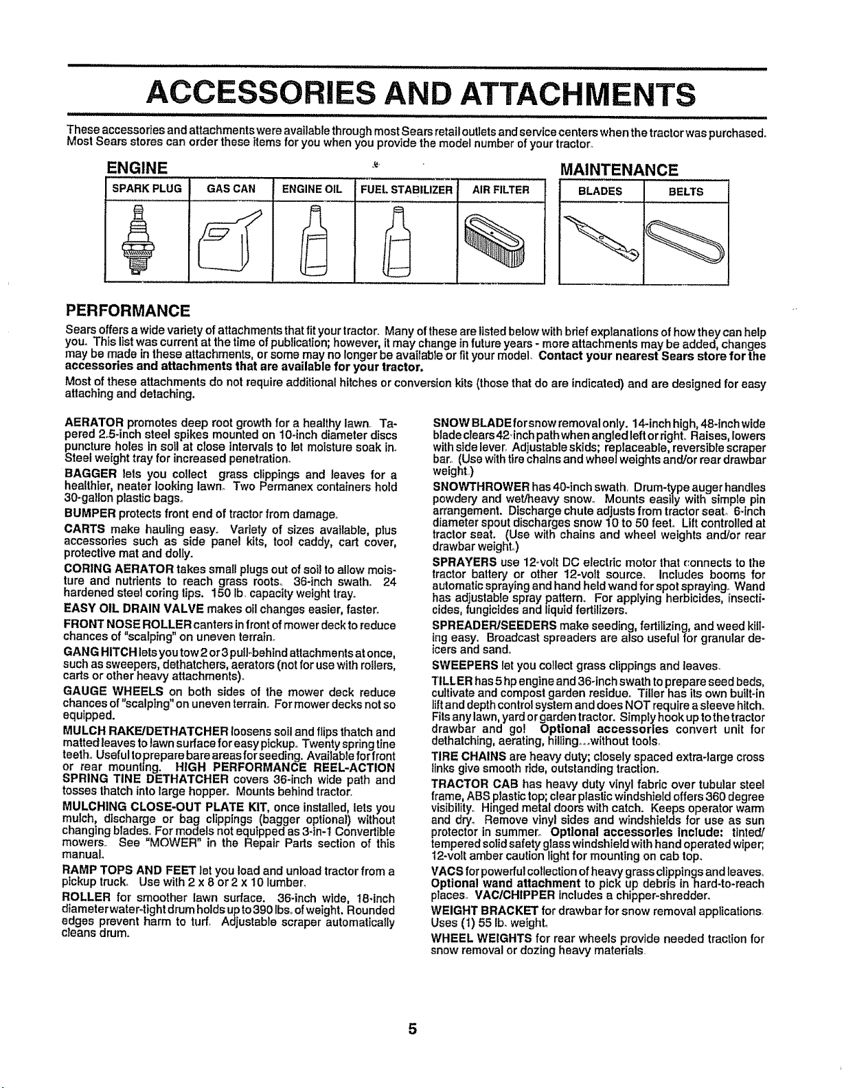
ENGINE MAINTENANCE
SPARK PLUG BLADES BELTS
GAS CAN ENGINEOIL
FUEL STABILIZER AIR FILTER
%
PERFORMANCE
Sears offersa wide variety of attachments that fit yourtractor., Many of these are listed below with brief explanations of how they can help
you° This list was current at the time of publication;however, it may change in future years- more attachments may be added, changes
may be made in these attachments, or some may no longer be available or fit your model. Contact your nearest Sears store for the
accessories and attachments that are available for your tractor,
Most of these attachments do not require additional hitches or conversion kits (those that do are indicated) and are designed for easy
attaching and detaching.
AERATOR promotes deep root growth for a healthy lawn.. Ta-
pered 2.5-inch steel spikes mounted on 10-inch diameter discs
puncture holes in soil at close intervals to let moisture soak in.
Steel weight tray for increased penetration°
BAGGER lets you collect grass clippings and leaves for a
healthier, neater looking lawno Two Permanex containers hold
30-gallon plastic bags°
BUMPER protects front end of tractorfrom damage.
CARTS make hauling easy. Variety of sizes available, plus
accessories such as side panel kits, too! caddy, cart cover,
protective mat and dolly_
CORING AERATOR takes small plugs out of soil to a!low mois-
ture and nutrients to reach grass roots° 36-inch swath_ 24
hardened steel coring tips, 150 lb. capacity weight trayn
EASY OIL DRAIN VALVE makes oil changes easier, faster.
FRONT NOSE ROLLER canters infront ofmower deckto reduce
chances of "scalping" on uneven terrain_
GANG HITCH lets you tow2 or3 puIFbehtndattachments at once,
such as sweepers, dethatchers, aerators (not for use withrollers,
carts or other heavy attachments).
GAUGE WHEELS on both sides of the mower deck reduce
chances of "scalping" on uneven terrain° For mower decks notso
equipped.
MULCH RAKE/DETHATCHER loosens soil and flips thatch and
matted leaves to lawn surface for easy pickup_ Twenty spring line
teeth° Useful toprepare bare areas forseeding. Available for front
or rear mounting. HIGH PERFORMANCE REEL-ACTION
SPRING TINE DETHATCHER covers 36-inch wide path and
tosses thatch into large hopper. Mounts behind tractor,
MULCHING CLOSE-OUT PLATE KIT, once installed, lets you
mulch, discharge or bag clippings (bagger optional) without
changing blades., For models not equipped as 3-in-1 Convertible
mowers. See "MOWER" in the Repair Parts section of this
manual°
RAMP TOPS AND FEET let you load and unload tractor from a
pickup truck. Usewith2x 8 or2x 10 lumber,
ROLLER for smoother lawn surface. 36_inch wide, 18-inch
diameter water.tight drum holds up to 390 Ibsoof weight. Rounded
edges prevent harm to turf, Adjustable scraper automatically
cleans drum.
SNOW BLADE forsnow removal only. 14-inch high, 48*inch wide
biadeclears42_inch pathwhen angtedleftor right, Raises, lowers
with side lever. Adjustable skids; replaceable, reversible scraper
bar. (Use with tire chains and wheel weights and/or rear drawbar
weight..)
SNOWTHROWER has 40-inch swath Drum-ty'pe auger handles
powdery and wet/heavy snow. Mounts easily with simple pin
arrangement. Discharge chute adjusts from tractor seal 6.inch
diameter spout discharges snow 10 to 50 feet. Lilt controlled at
tractor seat. (Use with chains and wheel weights and/or rear
drawbar weight_)
SPRAYERS use 12-volt DC electdc motor that _'onnects to lhe
tractor battery or other 12*volt source. Includes booms for
automatic sprayingand hand held wand for spot spraying° Wand
has adjustable spray pattern° For applying herbicides insecti*
cides, fungicides and tiquid fertilizers°
SPREADEPJSEEDERS make seeding, fertilizing, and weed kill-
ing easy. Broadcast spreaders are also useful for granular de-
icers and sand.
SWEEPERS let you collect grass clippings and leaves.
TILLER has 5 hp engine and 36-inch swath to prepare seed beds,
cultivate and compost garden restdueo Tiller has its own built-in
lift and depth control system and does NOT require a sleeve hitch°
Fits any lawn, yard or garden tractor. Simply hook up tothe tractor
drawbar and go! Optional accessories convert unit for
dethatching, aerating, hillingooowithout tools.
TIRE CHAINS are heavy duty; closely spaced extra-large cross
tlnks give smooth ride, outstanding tractton.
TRACTOR CAB has heavy duty vinyl fabric over tubular steel
frame, ABS plastic top; clear plastic windshield offers 360 degree
visibility, Hinged metal doors with catch. Keeps operator warm
and dry. Remove vinyl sides and windshields for use as sun
protector in summer° Optional accessories include: tinted/
tempered solidsafety"glasswindshield withhand operated wiper;,
12*volt amber caution light for mounting on cab top.
VACS for powerfulcollectionof heavy grassclippingsand leaves°
Optional wand attachment to picP, up debris in hard-to-reach
places.. VAC/CHIPPER includes a chipper*shreddero
WEIGHT BRACKET for drawbar for snow removal applications.
Uses (1) 55 ib_weight.
WHEEL WEIGHTS for rear wheels provide needed traction for
snow removal or dozing heavy materials
5
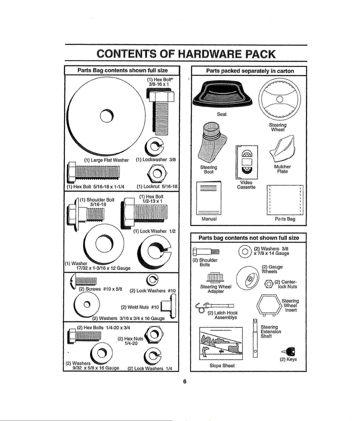
CONTENTS OF HARDWARE PACK
Pa_s Bag contents shown full size
(1) Large Flat Washer
--I,
(1) Hex Bolt 5/16-18 x 1-I/4
r (1) Shoulder Bolt
5/16-18
(1) Lockwasher 3/8
@
(1) Locknut 5116-18
(1) Hex Bolt
1/2-13 x I
iiiiiiiiii l
IJll|l||illl||
17132X 1-3/16 x 12 Gauge
(2) Screws #10 x 5!8 (2) Lock Washers #10
1
(_ (2) Weld Nuts #10
shers 3/16 x 3/4 x 16 Gauge _ _
...................... n i "::::" ...... : : .... - • i
mr'................_'_5_ * 114-20
(:) Washers "_===,_
9/32 x 518x 16 Gauge (2} Lo£,k,Washers 1/4 ......
Seat
Steering
Boot
Steering
Wheel
Mulcher
Plate
Manual
Video
Cassette
I !
| I
j
Parts Bag
(2) Shoulder
Bolts
Parts bag contents not shown full size
2) Washers 318
x 7/8 x 14 Gauge
Steering Wheel
Adapter
Assemblys
(2) Gauge
Wheels
2) Center-
lockNuts
SNteering
heel
insert
t teering
Extension
Shaft
(2) Keys
Slope Sheet
6
BLY
Your new tractor has been assembled at the factory withexception of those parts left unassembled for shipping purposes.
To ensure safe and proper operation of your tractor all parts and hardware you assemble must be tightened securely° Use
the correct tools as necessary to insure proper tightness.
TOOLS REQUIRED FOR ASSEMBL_
A socket wrench set will make assembly easier° Standard
wrench sizes are listed.
(1) 3/4" Socket w/drive rachet
(2) 7/16" wrenches (1) Phillips Screwdriver
(2) 1/2" wrenches Tire pressure gauge
(1) 9/16" wrench Utility knife
When right or left hand is mentioned in this manual, it
means when you are in the operating position (seated
behind the steering wheel).
TO REMOVE TRACTOR FROM CARTON
UNPACK CARTON
• Remove all accessible loose parts and parts cartons
from carton (See page 6)_
• Cut, from top to bottom, along lines on all tour corners
of carton, and lay panels flat.
= Check for any additional loose parts or cartons and
remove.
BEFORE ROLLING TRACTOR OFF SKID
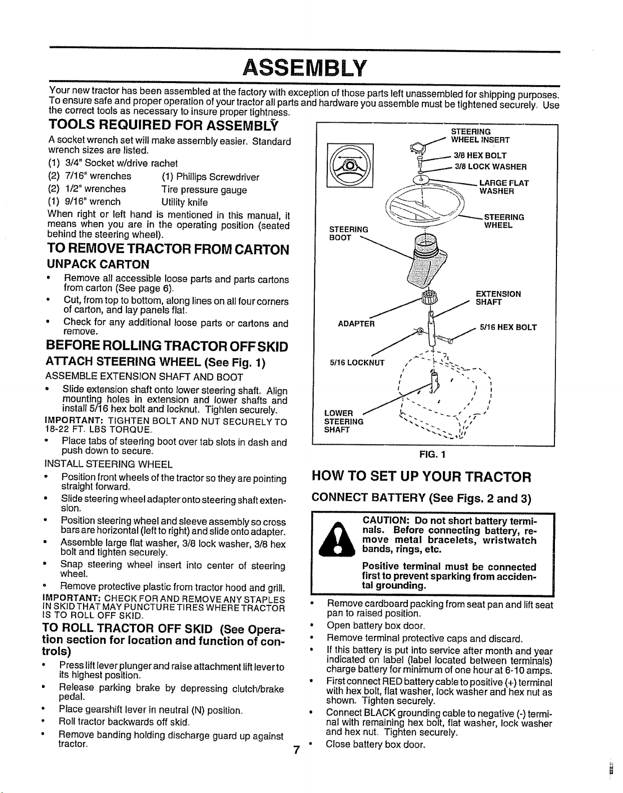
ATTACH STEERING WHEEL (See Fig. 1)
ASSEMBLE EXTENSION SHAFT AND BOOT
° Slide extension shaft onto lower steering shaft° Align
mounting holes in extension and iower shafts and
instal{ 5/16 hex bolt and locknuL Tighten securely_
IMPORTANT; TIGHTEN BOLT AND NUT SECURELY TO
18_22 FT_ LBSTORQUE.
° Place tabs of steering boot over tab slots in dash and
push down to secure.
INSTALL STEERING WHEEL
. Position front wheels of the tractor so they are pointing
straight forward°
• Slide steering wheel adapter onto steering shaft exten-
slono
• Position steering wheel and sleeve assembly so cross
bars are horizontal (left to right) and slide onto adapter.
• Assemble large flat washer, 3/8 lock washer, 3/8 hex
bolt and tighten securely.
° Snap steering wheel insert into center of steering
wheel
° Remove protective plastic from tractor hood and grill.
IMPORTANT; CHECK FOR AND REMOVE ANY STAPLES
IN SKID THAT MAY PUNCTURE TIRES WHERE TRACTOR
1STO ROLL OFF SKID_
TO ROLL TRACTOR OFF SKID (See Opera-
tion section for location and function of con-
trols)
° Press lift lever plunger and raise attachment lift lever to
its highest position.
• Release parking brake by depressing clutch!brake
pedal.
• Place gearshift lever in neutral (N) position..
° Roll tractor backwards off skid_
° Remove banding holding discharge guard up against
tractor°
STEERING
STEERING
7
SHAFT
FIG. 1
HOW TO SET UP YOUR TRACTOR
CONNECT BATTERY (See Figs, 2 and 3)
CAUTION: Do not short battery termi-
nals. Before connecting battery, re-
move metal bracelets, wristwatch
bands, rings, etc.
Positive terminal must be connected
first to prevent sparking from acciden-
tal grounding.
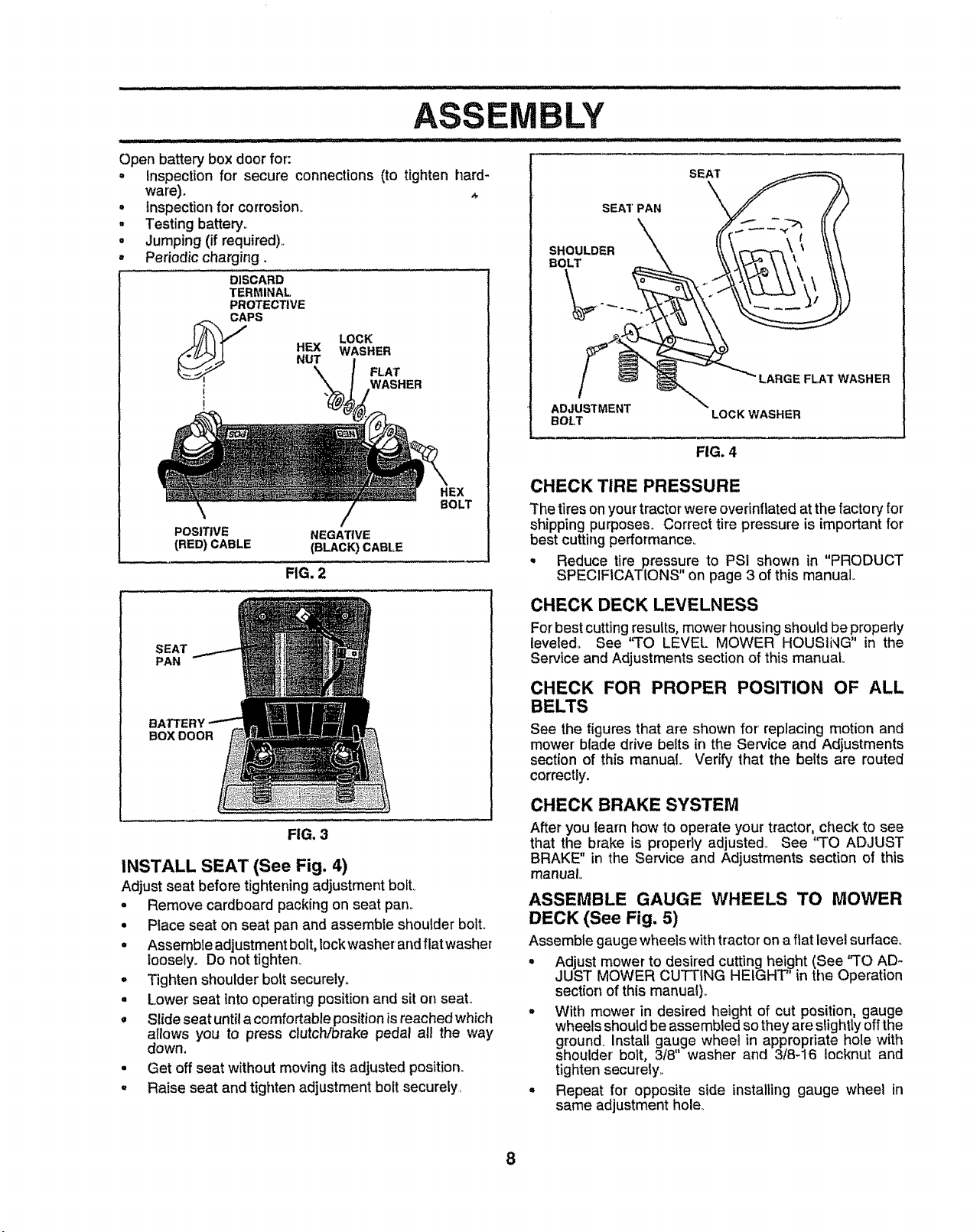
Remove cardboard packing from seat pan and lift seat
pan to raised position.
• Open battery" box door_.
• Remove terminal protective caps and discard°
° If this battery is put into service after month and year
indicated on label (label located between terminals)
charge battery for minimum of one hour at 6-10 amps.
• First connect RED battery cable to positive (+) terminal
with hex bolt, fiat washer, lock washer and hex nut as
shown° Tighten securely.
• Connect BLACK grounding cable to negative (-) termi-
nal with remaining hex bolt, fiat washer, lock washer
and hex nuL Tighten securely,,
= Close battery box door.
MBLY
Open batter,/box door for:
. Inspection for secure connections (to tighten hard-
ware).
= Inspection for corrosion_
= Testing battery°
= Jumping (if required),.
° Pedodic charging.
DISCARD
TERMINAL
PROTECTIVE
CAPS
NUT
t
LOCK
WASHER
FLAT
WASHER
POSITIVE
(RED) CABLE
NEGATIVE
(BLACK) CABLE
FIG. 2
HEX
BOLT
SEAT
PAN
BOX DOOR
FIG, 3
INSTALL SEAT (See Fig. 4)
Adjust seat before tightening adjustment boll
- Remove cardboard packing on seat pan°
• Place seat on seat pan and assemble shoulder bolt.
° Assemble adjustmentbolt, lockwasher and flat washer
loosely. Do not tighten,.
. Tighten shoulder bolt securely=
° Lower seat into operating position and sit on seat.,
• Slide seat untila comfortablepositionis reached which
a_lows you to press clutch/brake pedal all the way
down.
• Get off seat without moving its adjusted position,,
° Raise seat and tighten adjustment bolt securely,
SEAT
SEAT PAN
SHOULDER
BOLT
LARGE FLAT WASHER
ADJUSTMENT
BOLT
LOCK WASHER
FIG. 4
CHECK TIRE PRESSURE
The tireson your tractor were overinfiated at the factory for
shipping purposes. Correct tire pressure is important for
best cutting performance.
° Reduce tire press?,re to PSI shown in "PRODUCT
SPECIFtCATtONS on page 3 of this manual.
CHECK DECK LEVELNESS
For'best cutting results,mower housing should be property
leveled. See "TO LEVEL MOWER HOUSING" in the
Service and Adjustments section of this manual
CHECK FOR PROPER POSITION OF ALL
BELTS
See the figures that are shown for' replacing motion and
mower blade drive belts in the Service and Adjustments
section of this manual. Verify that the belts are routed
correctly.
CHECK BRAKE SYSTEM
After you learn how to operate your tractor, check to see
that the brake is propedy adjusted.. See 'q'O ADJUST
BRAKE" in the Service and Adjustments section of this
manual.
ASSEMBLE GAUGE WHEELS TO MOWER
DECK (See Fig. 5)
Assemble gauge wheels with tractor on a fiat level surface.
• Adjust mower to desired cutting height (See '_TOAD-
JUST MOWER CUTTING HEIGHT" in the Operation
section of this manual).
• With mower in desired height of cut position, gauge
wheels should be assembled so they are slightly off the
ground. Install gauge wheel in appropriate hole with
shoulder bolt, 3/8' washer and 3t8-16 Iocknut and
tighten securely,.
° Repeat for opposite side installing gauge wheel in
same adjustment hole,,
8
......................................... ,,,, ,,, ,,,,,
GAUGE WHEEL
MOUNTING
3/8" WASHER BOLT
FIG. 5
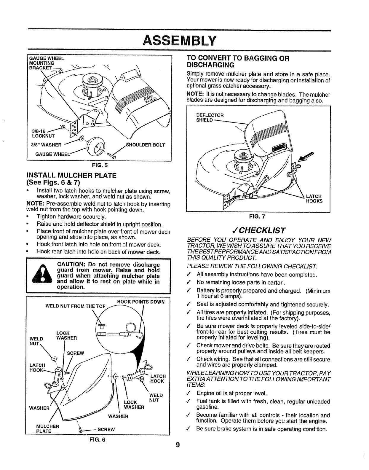
INSTALL MULCHER PLATE
(See Figs. 6 & 7)
• Install two latch hooks to mulcher plate using screw,
washer, lock washer, and weld nut as shown_
NOTE: Pre-assemble weld nut to latch hook by inserting
weld nut from the top with hook pointing down°
• Tighten hardware securely.
• Raise and hold deflector shield in upright position.
• Place front of mulcher plate over front of mower deck
opening and slide into place, as shown.
• Hook front latch into hole on front of mower deck_
• Hook rear latch into hole on back of mower deck,,
iJllill ill i .,,,,,,,,,,,
CAUTION: Do not remove discharge I
guard from mower. Raise and hold
I
guard when attaching mulcher plate
and allow it to rest on plate while in
operation.
HOOK POINTS DOWN
WELD WASHER
LATCH
ASSEMBLY
TO CONVERT TO BAGGING OR
DISCHARGING
Simply remove mulcher plate and store in a safe place.
Your mower is now ready for discharging or installation of
optional grass catcher accessory.
NOTE: It is not necessary to change blades. The mulcher
blades are designed for discharging and bagging alsoo
DEFLECTOR
SHIELD
LATCH
HOOKS
FIG. 7
v" CHECKLIST
BEFORE YOU OPERATE AND ENJOY YOUR NEW
TRACTOR, WE WISH TO ASSURE THAT YOU RECEIVE
THEBEST PERFORMANCE AND SATISFACTION FROM
THIS QUALITY PRODUCT.
PLEASE REVIEW THE FOLLOWING CHECKLIST:
v" All assembly instructions have been completed,
/ No remaining loose parts in carton,
,/ Battery is properlyprepared and charged,. (Minimum
t hour at 6 amps),
#' Seat is adjusted comfortably and tightened securely.
/ All tires are properly inflated. (For shipping purposes,
the tires were ovennftated at the factory).
,/ Be sure mower deck is properly leveled side-to-side/
front-to-rear for best cutting results. (Tires must be
properly inflated for leveling).
v" Check mower and drive belts. Be sure they are routed
properly around pulleys and insideall belt keepers.
1/" Check wiring. See that all connections are still secure
and wires are properly clamped°
WASHER
MULCHER
PLATE
LOCK
WASHER
FIG. 6
LATCH
HOOK
WELD
NUT
WHILE LEARNING HOW TO USE YOUR TRACTOR, PAY
EXTRA ATTENTtON TO THE FOLLOWING IMPORTANT
ITEMS:
,/ Engine oil is at proper level.
,/ Fuel tank is filled with fresh, clean, regular unleaded
gasoline.
,/ Become familiar with all controls - their location and
function.. Operate them before you start the engine.
/ Be sure brake system is in safe operating condition_
9

OPERATION
These symbols may appear on your tractor'or in literature supplied withthe producL Learn and understand their meaning°
BATTERY
ENGINE ON
CAUTION OR REVERSE FORWARD FAST SLOW
WARNING
ENGINE OFF OIL PRESSURE CLUTCH LIGHTS ON LIGHTS OFF
FUEL CHOKE MOWER HEIGHT DIFFERENTIAL PARKING BRAKE UNLOCKED
LOCK LOCKED
MOWER LIFT
R N H
REVERSE NEUTRAL
ATTACHMENT
CLUTCH ENGAGED
HIGH LOW PARKING BRAKE
ATTACHMENT
CLUTCH DISENGAGED
IGNITION
DANGER, KEEP HANDS AND FEET AWAY
HYDROSTATIC FREE WHEEL
(Hydro Models only)
10
KNOW YOUR TRACTOR
Ill IJII'llll'll"
OPERATION
lllll i,,i ii i mlmll
READ THIS OWNER'S MANUAL AND SAFETY RULES BEFORE OPERATING YOUR TRACTOR
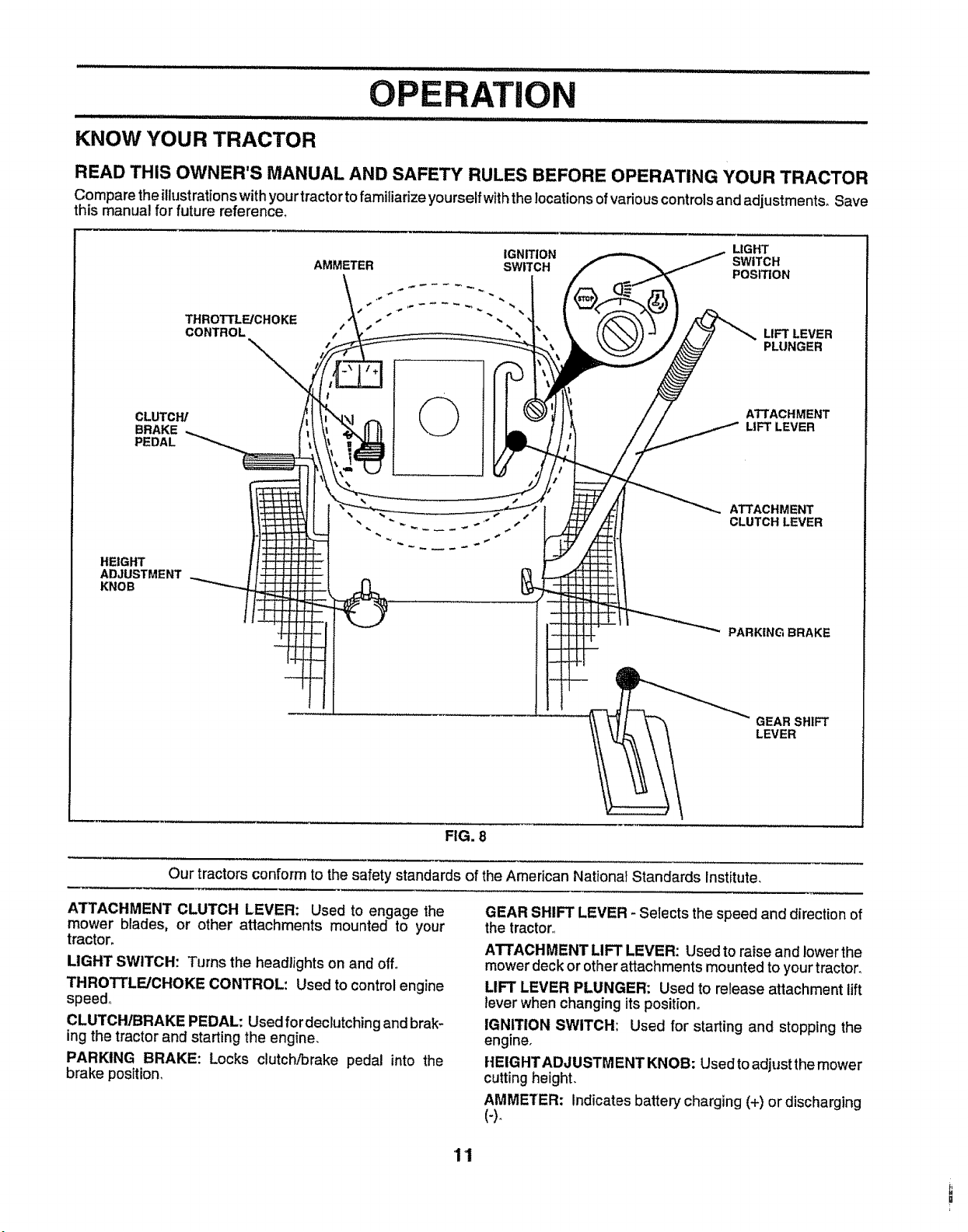
Compare the illustrationswithyourtractorto familiarize yourselfwiththe locationsof variouscontrolsand adjustments_Save
this manua! for future referenced
THROTTLE/CHOKE
CONTROL
CLUTCW
BRAKE
PEDAL
IGNITION LIGHT
AMMETER SWITCH SWITCH
POSITION
LIFT LEVER
PLUNGER
ATTACHMENT
LIFT LEVER
HEIGHT
ADJUSTMENT
KNOB
ATTACHMENT
CLUTCH LEVER
PARKING BRAKE
GEAR SHIFT
LEVER
FIG. 8
Our tractors conform to the safety standards of the American National Standards Institute,
ATTACHMENT CLUTCH LEVER: Used to engage the
mower blades, or other attachments mounted to your
tractor_
LIGHT SWITCH: Turns the headlights on and off.
THROTTLE/CHOKE CONTROL: Used to control engine
speed°
CLUTCHtBRAKE PEDAL: Used fordeclutching andbrak-
ing the tractor and starting the engine,
PARKING BRAKE: Locks clutch/Drake pedal into the
brake position,
GEAR SHIFT LEVER - Selects the speed and direction of
the tractor,,
ATTACHMENT LIFT LEVER: Used to raise and lower the
mowerdeck or otherattachments mounted to your tractor.
LIFT LEVER PLUNGER: Used to release attachment lift
lever when changing its position°
IGNITION SWITCH: Used for starting and stopping the
engine.
HEIGHTADJUSTMENT KNOB: Usedto adjustthe mower
cuttingheight.
AMMETER: Indicates battery charging (+) or discharging
'1'I
OP
!
The operation of any tractor can result in foreign objects thrown into the eyes, which can I
result in severe eye damage. Always wear safety glasses or eye shields while operating your |
tractor or performing any adjustments or repairs. We recommend a wide vision safety mask |
over the spectacles or standard safety glasses. |
I
t
HOW TO USE YOUR TRACTOR
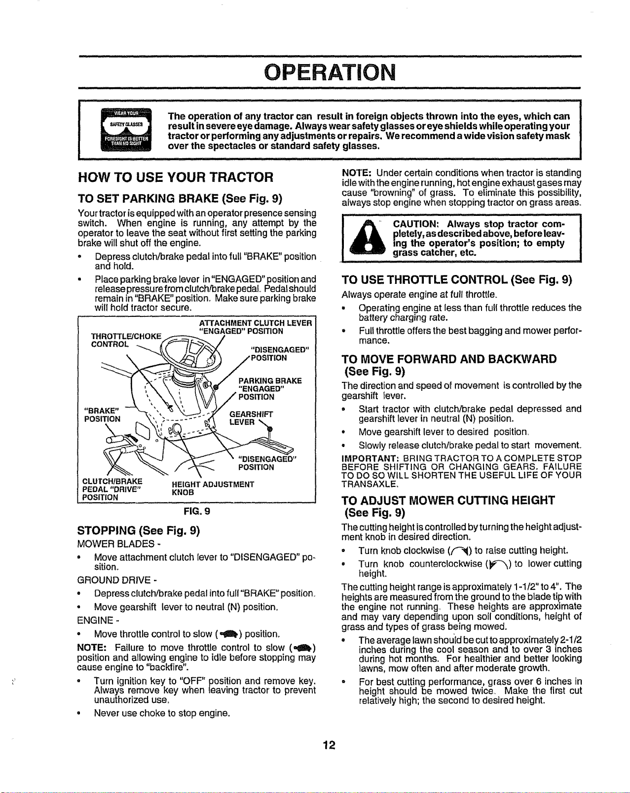
TO SET PARKING BRAKE (See Fig. 9)
Your tractoris equipped with an operator presence sensing
switch. When engine is running, any attempt by the
operator to leave the seat without first setting the parking
brake will shut off the engine.
• Depress clutch/brake pedal into full "BRAKE" position
and hold.
• Place parking brake lever in"ENGAGED" positionand
release pre,ssure fr?m clutch/brake pedal Pedalshould
remain in BRAKE position. Make sure parkingbrake
will hold tractor secure.
ATTACHMENT CLUTCH LEVER
"ENGAGED" POSITION
THROTTLE/CHOKE _ /
CONTROL _ fF-_! c_ _ / ....
_--,_. /t._ ^_',_, DISENGAGED
| \,, \ _ "_'_ "ENGAGED"
'*BRAKE" -"k_ ',. % \-_, -+-f'/ _._,n_ .....
POSITI
_.. _ / _ POSITION
CLUTCHIBRAKE HEIGHT ADJUSTMENT
PEDAL "DRIVE" KNOB
POSITION
FIG. 9
STOPPING (See Fig. 9)
MOWER BLADES -
• Move attachment ctutch iever to "DISENGAGED" po-
sition,
GROUND DRIVE -
. Depress clutch/brake pedal into full "BRAKE" position.
° Move gearshift lever to neutral (N) position.
ENGINE -
. Move throttle control to slow (,,_lh) position_
NOTE: Failure to move throttle control to slow (,,g_)
position and allowing engine to idle before stopping may
cause engine to "backfire".
. Turn ignition key to "OFF" position and remove key.
Always remove key when leaving tractor to prevent
unauthorized use+
• Never use choke to stop engine.
NOTE: Under certain conditionswhen tractor is standing
idle with the engine running,hot engine exhaust gases may
cause "browning" of grass. To eliminate this possibility,
always stop engine when stopping tractor on grass areas.
! _IL" CAUTION: AlwaYs Stop tractor corn-
| _ pletely, asdescribedabove, beforeleav-
| D mg the operator's position; to empty
,! grass catcher, etc. .....
TO USE THROTTLE CONTROL (See Fig, 9)
Always operate engine at full thrott{e.
° Operat{ng engine at less than full throttle reduces the
battery charging rate.
. Futtthrottle offers the best bagging and mower perfor-
mance.
TO MOVE FORWARD AND BACKWARD
(See Fig. 9)
The directionand speed of movement is controlledby the
gearshift lever.
, Start tractor with clutch/brake pedal depressed and
gearshift lever in neutral (N) position.
• Move gearshift lever to desired position+
. Slowly release clutch/brake pedal to start movemenL
IMPORTANT: BRING TRACTOR TO A COMPLETE STOP
BEFORE SHIFTING OR CHANGING GEARS. FAILURE
TO DO SO WILL SHORTEN THE USEFUL LIFE OF YOUR
TRANSAXLE,
TO ADJUST MOWER CUTTING HEIGHT
(See Fig. 9)
The cutting height is controlled by turning the height adjust-
ment knob in desired direction.
° Turn knob clockwise (F-_) to raise cutting height.
• Turn knob counterciocl_wise (p'-_) to lower cutting
height.
The cutting height range is approximately 1-1/2" to 4". The
heights are measured from the ground to the blade tip with
the engine not running. These heights are approximate
and may vary depending upon soil conditions, height of
grass and types of grass being mowed°
+ The average lawn should be cut to approximately 2-1/2
inches during the cool season and to over 3 inches
during hot months. For healthier and better looking
lawns, mow often and after moderate growth+
o For best cutting performance, grass over 6 inches in
height should be mowed twice. Make the first cut
relativelyhigh; the second to desired height.
12
ill i,,i,iHI"III'II' rill ...................
OPERATION
iii lll,l,,i,ii,ll IL"_ ..............
IIIl,,llI II 'i'll' I I .......
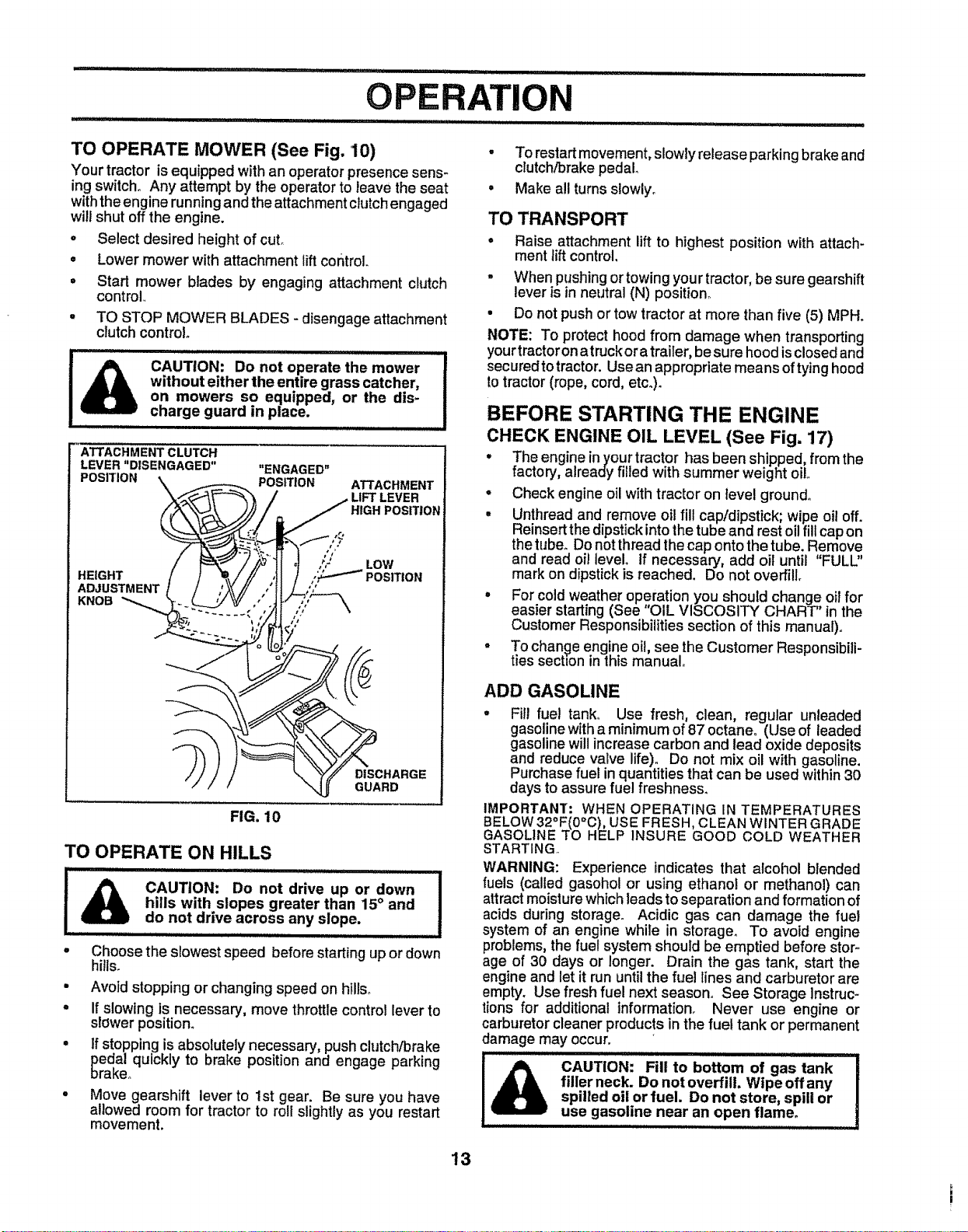
TO OPERATE MOWER (See Fig. '10)
Your tractor is equipped with an operator presence sens-
ing switch° Any attempt by the operator to leave the seat
withthe engine running and the attachment clutchengaged
will shut off the engine.
° Select desired height of cuL
= Lower mower with attachment lift control.
° Start mower blades by' engaging attachment clutch
control
• TO STOP MOWER BLADES- disengage attachment
clutch control
IA ............................f
CAUTION: Do not operate the mower
without either the entire grass catcher,
on mowers so equipped, or the dis-
charge guard in place.
FIG. 10
TO OPERATE ON HILLS
CAUTION: Do not drive up or down
hills with slopes greater than 15° and
do not drive across any slope.
,,,,,,, ,,, ...............
° Choose the slowest speed before starting up or down
hills.
- Avoid stopping or changing speed on hills°
o If slowing is necessary, move throttle control lever to
slower position_
° If stopping is absolutely necessary, push clutch/brake
pedal quickly to brake position and engage parking
brake°
o Move gearshift lever to 1st gear. Be sure you have
allowed room for tractor to roll slightly as you restart
movement.
• To restartmovement, slowly release parking brake and
clutch!brake pedal
• Make all turns slowly°
TO TRANSPORT
° Raise attachment lift to highest position with attach-
ment lift control,
• When pushing or towing your tractor, be sure gearshift
lever is in neutral (N) position_
• Do not push or tow tractor at more than five (5) MPH.
NOTE: To protect hood from damage when transporting
your tractor on atruck or atrailer, be sure hood is closed and
secured to tractor. Usean appropriate means of tying hood
to tractor (rope, cord, etco).
BEFORE STARTING THE ENGINE
CHECK ENGINE OIL LEVEL (See Fig. 17)
• The engine in your tractor has been shipped, from the
factory, already filled with summer weight oil.,
° Check engine oil with tractor on level ground°
° Unthread and remove oil fill cap/dipstick; wipe oi! off.
Reinsertthe dipstickinto the tube and rest oil fill cap on
thetube. Do not thread the cap ontothe tube. Remove
and read oil level If necessary, add oil until "FULL"
mark on dipstick is reached. Do not overfill
• For cold weather operation you should change oil for
easier starting(See "OIL VISCOSITY CHART" in the
Customer Responsibilitiessection of this manual),.
° To change engine oil, see the Customer Responsibili-
ties section in this manual.
ADD GASOLINE
• Fitl fue! tank° Use fresh, clean, regular unleaded
gasoline with a minimum of 87 octane. (Use of leaded
gasoline will increase carbon and lead oxide deposits
and reduce valve life). Do not mix oil with gasoline.
Purchase fuel in quantities that can be used within 30
days to assure fuel freshness.
IMPORTANT: WHEN OPERATING IN TEMPERATURES
BELOW32°F(0°0), USE FRESH, CLEAN WINTER GRADE
GASOLINE TO HELP INSURE GOOD COLD WEATHER
STARTING.
WARNING: Experience indicates that alcohol blended
fuels (called gasohol or using ethanot or methanol) can
attract moisture which leads to separation and formation of
acids during storage. Acidic gas can damage the fuel
system of an engine while in storage. To avoid engine
problems, the fuel system should be emptied before stor-
age of 30 days or longer. Drain the gas tank, start the
engine and let it run until the fuel lines and carburetor are
empty. Use fresh fuel next season,. See Storage Instruc-
tions for additional information. Never use engine or
carburetor cleaner products in the fuel tank or permanent
damage may occur.
IHIIIIIIIII II II I .........................
CAUTION: Fill to bottom of gas tank
filler neck. Do not overfill. Wipe off any
spilled oil or fuel. Do not store, spill or
use gasoline near an open flame,
13
ATION
TO START ENGINE (See Fig. 9)
When starting the engine for the first time or if the engine
has run out of fuel, it will take extra cranking time to move
fuel from the tank to the engine.
, Depress clutch/brake pedal and set parking brake.
° Place gear shiftlever in neutral (N) position.
• Move attachment clutch to "DISENGAGED" position°
° Move throttle control to choke (N) position.
Note: Before starting, read the warm and cold starting
proceduresbelow.
° insertkeyintoignition and turnkeyctockwise to"START"
positionand release key as soonas engine starts. Do
not run starter continuouslyfor more than fifteen sec-
onds per minute. If the engine does not start after
several attempts, move throttle control to fast (,_)
position,wait afewminutesandtryagain, tfenginestill
does not start, move the throttle control back to the
choke ([\{) position and retry_
WARM WEATHER STARTING (50° F and above)
° When engine starts, move the throttlecontroltothe fast
(,tel) position.
• The attachmentsand ground drivecan now be used. If
the enginedoes not accept the load, restartthe engine
and allow itto warm up for one minute usingthe choke
as described above.
COLD WEATHER STARTING ( 50° F and below)
° When engine starts,allow engineto runwith the throttle
control in the choke (N) position unt!lthe engine runs
roughly, then move tt-irottlecontrol to fast (,_) position.
This may require an engine warm-up period from
severalseconds to several minutes, depending onthe
temperature.
° The attachments can also be used during the engine
warm-up period_
NOTE: ff at a high altitude (above 3000 feet) or in cord
temperatures (below 32 F) the carburetor fuel mixture may
need to be adjusted for best engine performance, See "TO
ADJUST CARBURETOR" in the Serv{ce and Adjustments
section of this manual,
dry before mowing,
= Always operate engine at full throttle when mowing to
assure better mowing performance and proper dis,-
charge of material, Regulate ground speed by select-
ing a low enough gear' to give the mower cutting
performanceas welt as the quality of cut desired_
° When operating attachments, select a ground speed
that will suit the terrain and give best performance of
the attachment being used,
MOWING TIPS
° Mower should be ,properly leveled for best mow!ng
performance° See q'O LEVEL MOWER HOUSING in
the Service and Adjustments section of this manual,
• The left hand side of mower should be used for trim-
mingo
= Drive so that clippings are discharged onto the area
that has been cut. Have the cut area to the rightof the
machine,. This will result in a more even distribution of
clippings and more uniform cutting,
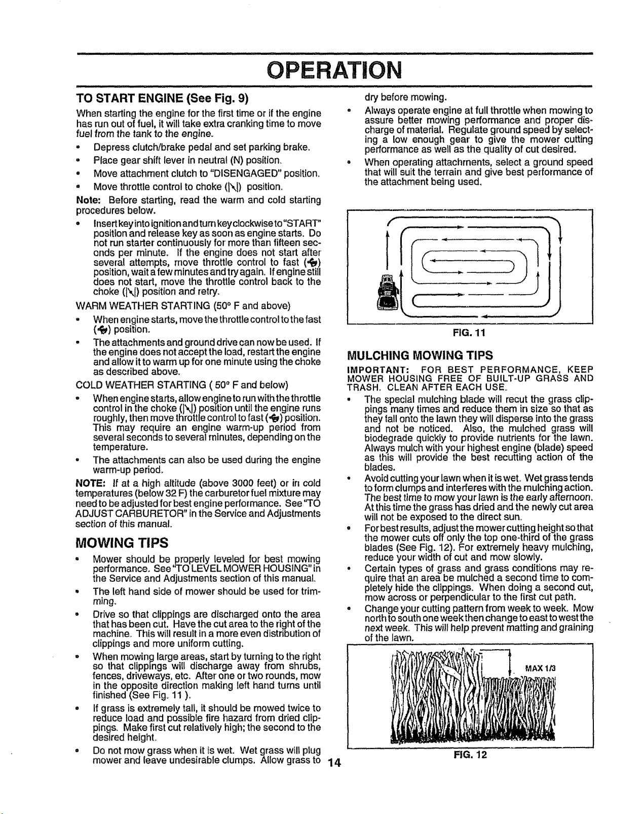
° When mowing large areas, start by turning to the right
so that clippings wiU discharge away from shrubs,
fences, driveways, etc, After one or two rounds, mow
in the opposite direction making left hand turns until
finished (See Fig, 11 )_
• If grass is extremely tall, it should be mowed twice to
reduce load and possible fire hazard from dried clip-
pings, Make first cut relatively high; the second to the
desired height°
° Do not mow grass when it is wet. Wet grass will plug
mower and leave undesirable clumps. Allow grass to
FIG. 11
MULCHING MOWING TIPS
IMPORTANT: FOR BEST PERFORMANCE, KEEP
MOWER HOUSING FREE OF BUILT-UP GRASS AND
TRASH° CLEAN AFTER EACH USE°
• The special mulching blade will recut the grass clip-
pings many times and reduce them in size so that as
they fall ontothe lawn they will disperse into the grass
and not be noticed. Also, the mulched grass will
biodegrade quickfy to provide nutrients for the lawn.
Always mulch with your'highest engine (blade) speed
as this will provide the best recutting action of the
blades.
• Avoid cutting your lawn when it is wet,, Wet grass tends
to form clumps and interferes with the mulching action.
The best time to mow your lawn is the early afternoon,
At this time the grass has dried and the newly cut area
will not be exposed to the direct sun°
° For best results, adjust the mower cutting height sothat
the mower cuts offonly the top one-third of the grass
blades (See Fig. 12). For extremely heavy mulching,
reduce your width of cut and mow slowly.
° Certai n types of grass and grass conditions may re-
quire that an area be mulched a second time to com-
pletely hide the clippings. When doing a second cut,
mow across or perpendicular to the first cut path,
o Change your cutting pattern from week to week, Mow
north to south one week then change to east to west the
next week. This will help prevent matting and graining
of the lawn,
MAX 1/3
FIG. 12
14
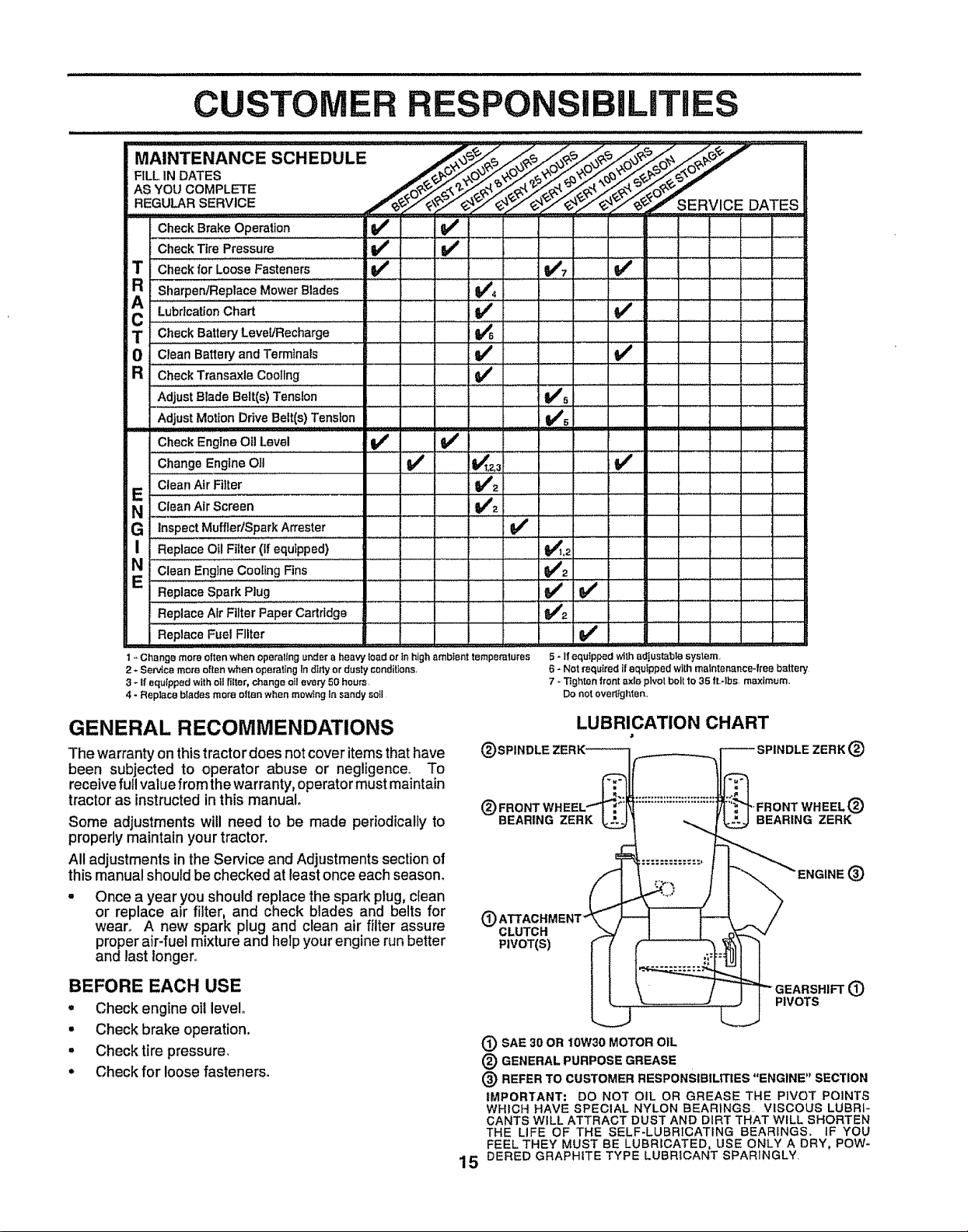
CUSTOMER R TiES
SO.EOO'E
Check Brake Operation if Q,-J
Check Tire Pressure i/ V _
Check for Loose Fasteners if ik/7 6/
R sharpeniReplace Mower Blades 6/,=
LUb;i;atto;Cha. .... 6/ .... 6/: : ; ; .
C ........................................... = ........
Check Battery Level/Recharge I_ .
= = ...................
0 Clean Battery and Terminals If 6/
R CheckTransaxleCoollng a##
,AdjUSt Blad e Belt(s) Tension ............ Vrs
Adjust Motion Drive Belt(s) Tension VPs
Check Engine Oil Level if if
Change Engine O]1 V/' li_t 6/
Clean Air.Fi!ter ... V_2 ..................
NE clean Air Screen I_=
G ""inspect MuffledSpark Attester 6/
NI Replace Oil Fi_ter (if equipped) !_1.2
Clean Engine Cooling Fins .... 6/2
E ................................ReplaceSparkPlug ' .... ' ' ' ............ _!6/: .........
Rap,aceA_r'Fl'i'i'e;_'aPerCa,.dgO............................. 6/_...............
Replace Fuel Filter 6/
f - Change more often when eperaltng under a heavy {oad or in high ambfent temperatures
2 * Service more often when operating In dirty or dusty condiUans,
3 - If equipped with oil filter, change oil every 50 hours,
4 - Replace biades more often when mowing In sandy soil
5 - If equipped with adjustable system,
6 - Not required if equipped with maintenance-free battery
7 - Tighten front axle pivot bolt 1o35 ttAbs, maximum,,
Do not overtighlen..
GENERAL RECOMMENDATIONS
The warranty on this tractor does not cover items that have
been subjected to operator abuse or negligence. To
receive full value from the warranty, operator must maintain
tractor as instructedin this manual°
Some adjustments will need to be made periodically to
properly maintain your tractor.
All adjustments in the Service and Adjustments section of
this manual should be checked at least once each season.
Once a year you should replace the spark plug, clean
or replace air filter, and check blades and belts for
wean A new spark plug and clean air filter assure
proper air-fuel mixture and help your engine run better
and last longer°
BEFORE EACH USE
. Check engine oil level
• Check brake operation.
, Checktire pressure,
• Check for loose fasteners.
15
LUBRICATION CHART
(_)SPINDLE ZERK_
ZERK(_
"FRONT WHEEL®
BEARING ZERK
._ o
SAE 30 OR 10W30 MOTOR OIL
® GENERAL PURPOSE GREASE
(_) REFER TO CUSTOMER
RESPONSIBILITIES "ENGINE" SECTION
IMPORTANT: DO NOT OIL OR GREASE THE PIVOT POINTS
WHICH HAVE SPECIAL NYLON BEARINGS VISCOUS LUBRI-
CANTS WELL ATTRACT DUST AND DIRT THAT WILL SHORTEN
THE LIFE OF THE SELF-LUBRICATING BEARINGS. IF YOU
FEEL THEY MUST BE LUBRICATED, USE ONLY A DRY, POW-
DERED GRAPHITE TYPE LUBRICANT SPARINGLY.
TRACTOR
Always observe safety rules when performing any mainte-
nanceo
BRAKE OPERATION
If tractor requires more than six (6) feet stoppirtg distance
at high speed in highest gear, then brake must be adjusted..
(See "TO ADJUST BRAKE" in the Service and Adjust-
ments section of this manual)_
TIRES
= Maintain proper' air pressure in all tires (See "PROD-
UCT SPECIFICATIONS" on page 3 of this manual).
• Keep tires free of gasoline, oil, or insectcontrol chemi-
cals which can harm rubber.
. Avoid stumps, stones, deep ruts, sharp objects and
other hazards that may cause tire damage.,
BLADE CARE
For best results mower blades must be kept sharp. Re-
place bent or damaged blades.
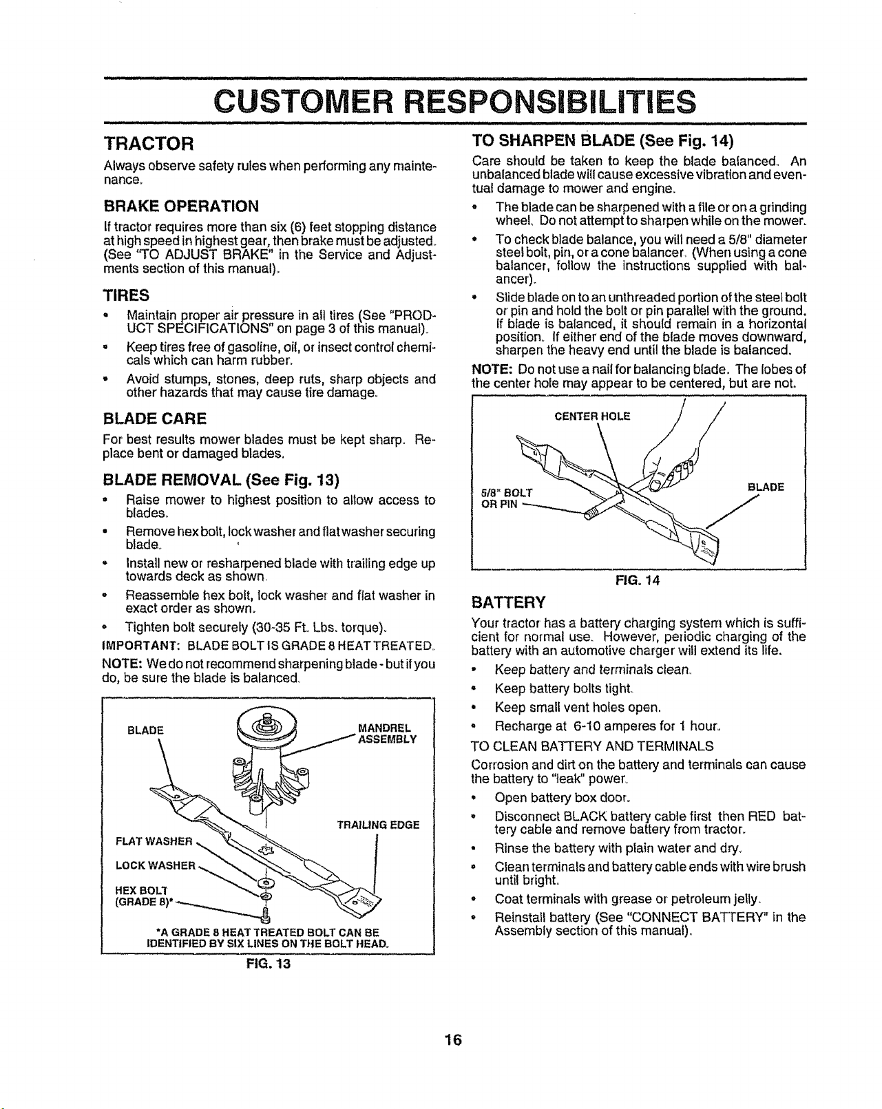
BLADE REMOVAL (See Fig. 13)
= Raise mower to highest position to allow access to
blades..
° Remove hex bolt, Iockwasher and flat washer securing
blade_
- Install new or resharpened blade with trailing edge up
towards deck as shown,
• Reassembfe hex bolt, lock washer and fiat washer in
exact order as shown°
° Tighten bolt securely (30-35 Ft. Lbs. torque).
IMPORTANT: BLADE BOLT IS GRADE8 HEATTREATED..
NOTE: We do not recommend sharpening blade- but ifyou
do, be sure the blade is balanced°
BLADE
TRAILING EDGE
FLAT WASHER !
LOCK WASHER
HEX BOLT
(GRADE
*A GRADE 8 HEAT TREATED BOLT CAN BE
IDENTIFIED BY SIX LINES ON THE BOLT HEAD.
TO SHARPEN BLADE (See Fig. 14)
Care should be taken to keep the blade balanced,. An
unbalanced bladewillcause excessive vibrationand even-
tual damage to mower and engine_
° The blade can be sharpened with a file or on a grinding
wheel, Do not attempt to sharpen while on the mower°
° To check blade balance, you will need a 5/8" diameter
steel bolt, pin, or a cone balancer, (When using a cone
balancer, follow the instructions supplied with bal-
ancer).
° Slide blade on to an unthreaded portion of the steel bolt
or' pin and hold the bolt or pin parallel with the ground.
If blade is balanced, it should remain in a horizontal
position. If either end of the blade moves downward,
sharpen the heaw end until the blade is balanced.
NOTE: Do not use a nail for balancing blade.. The lobes of
the center hole may appear to be centered, but are not.
CENTER HOLE / /
o.
FIG. 14
BATTERY
Your tractor has a battery charging system which is suffi-
cient for normal use. However, periodic charging of the
battery with an automotive charger' will extend its life.
• Keep battery and terminals clean_
° Keep battery bolts tight.
. Keep small vent holes open,
° Recharge at 6-10 amperes for 1 hour.
TO CLEAN BATTERY AND TERMINALS
Corrosion and dirt on the battery and terminals can cause
the battery to "leak" power_
• Open battery box door.
° Disconnect BLACK battery cable first then RED bat-
tery cable and remove battery from tractor'.
• Rinse the battery with plain water and dry.
° Clean terminals and battery cable ends with wire brush
until bright.
° Coat terminals with grease or petroleum jelly..
° Reinstall battery (See "CONNECT BATTERY" in the
Assembly section of this manual).,
FIG. 13
16
V-BELTS
/i,,,,,,,,,,,,,,,, , ,
CUSTOMER
RESPONSIBiLiTIES
Check V-belts for deterioration and wear after 100 hours of
operation and replace if necessary. The belts are not
adjustable,. Replace belts if they begin to slip from wean
TRANSAXLE COOLING
Keep transaxle free from build_upof dirt and chaff which
can restrict cooting.
ENGINE
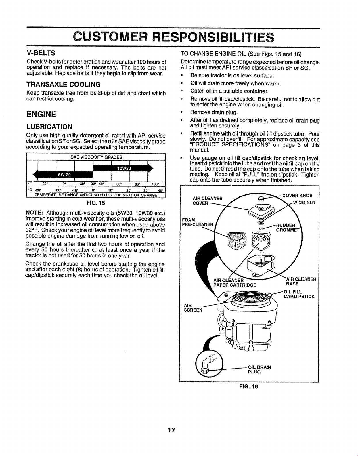
LUBRICATION
Only use high quality detergent oil rated with API service
classification SF orSGo Select the oil's SAE viscosity grade
according to your expected operating temperature.
SAE VISCOSITY GRADES
<
_F "2'€)'; 0° 30" 32' 40" 60 = 80 = t09"
aC _30 a _20_ _t0 ° D" 10_ 20' 30" 40"
TEMPERATURE RANGE ANTICIPATED BEFORE NEXT OiL CHANGE
FIG. 15
NOTE: Although multi-viscosity oils (5W30, I0W30 etc,)
improve starting in cold weather, these muIti-viscosity oils
wil! result in increased oil consumption when used above
32°F, Checkyour engine oil level more frequently to avoid
possible engine damage from running low on oil
Change the oil after the first two hours of operation and
every 50 hours thereafter or at least once a year if the
tractor is not used for 50 hours in one year.
Check the crankcase oil level before starting the engine
and after each eight (8) hours of operation. Tighten oil fill
capldipstick securely each time you check the oil level.
TO CHANGE ENGINE OIL (See Figs. 15 and 16)
Determine temperature range expected before oil change°
All oil must meet API service classification SF or SG,
• Be sure tractor is on level surface°
° Oil willdrain more freely when warm.
• Catch oil in a suitable container°
, Remove oil fill cap!dipsticko Be careful not to allow dirt
to enter the engine when changing oil
• Remove drain plug.
, After oil has drained completely, replace oil drain plug
and tighten securely.
• Refill engine with oil through oil fill dipstick tube. Pour
slowly. Do not overfill For approximate capacity see
"PRODUCT SPECIFICATIONS" on page 3 of this
manual.
Use gauge on oil fill cap/dipstick for checking level°
Insert dipstickinto the tube and rest the oil fill cap onthe
tube. Do not thread the cap onto the tube when taking
reading° Keep oil at "FULL" line on dipstick. Tighten
cap onto the tube securely when finished°
AIR CLEANER KNOB
COVER , WING NUT
FOAM
PRE-CLEANER
AIR
SCREEN
PAPER CARTRIDGE
AIR CLEANER
BASE
CAP/DIPSTICK
pRAIN
PLUG
FIG. 16
17

CU
CLEAN AIR SCREEN (See Fig. 16) CLEAN AIR INTAKE/COOLING AREAS
Air screen must be kept free of dirt and chaff to prevent
engine damage from overheating, Clean with a wire brush
or' compressed air to remove dirt and stubborn dried gum
fibers_
AIR FILTER (See Fig. 16)
'(our engine will not run properly using a dirty air filter.
Clean the foam pro-cleaner after every 25 hours of opera-
tion or every season° Service paper cartridge every 100
hours of operation or every season, whichever occurs first.
Service air cleaner more often under' dusty conditions.
• Remove knob and cover'.
o Remove wing nut and air cleaner from base.
TO SERVICE PRE-CLEANER
° Slide foam pre_cleaner off cartridge..
• Wash it in liquid detergent and water.
. Squeeze it dry in a clean cloth.
• Saturate it in engine oil., Wrap it in clean, absorbent
cloth and squeeze to remove excess oilo
TO SERVICE CARTRIDGE
° Gently tap the flat side of the paper cartridge to dis-
lodge dirt. Do not wash the paper cartridge or use
pressurized air, as this will damage the cartridge,
Replace a dirty, bent, or damaged cartridge.
° Reinstall the pre-cleaner (cleaned and oiled) over the
paper cartridge.
° Reassemble air cleaner, wing nut, cover and tighten
knob securely.
To insure proper cooling, make sure the grass screen,
coolingfins, and other external surfaces of the engine are
kept clean at all times,
Every 100 hours of operation (more often under extremely
dusty, dirty conditions), remove the blower housing and
other cooling shrouds. Clean the cooling fins and external
surfaces as necessary. Make sure the cooling shrouds are
reinstalled.,
NOTE; Operating the engine with a blocked grass screen,
dirty or plugged cooling fins, and/or cooling shrouds re-
moved will cause engine damage due to overheating.
MUFFLER
inspectand replace corroded muffler and spark arrestor (if
equipped) as it could create a fire hazard and/or damage.
SPARK PLUGS
Replace spark plugs at the beginning of each mowing
season or after every I00 hours of operation, whichever
occursfirst. Spark p[ug type and gap setting are shown in
"PRODUCT SPECIFICATIONS" on page 3 of this manual.
18

RESPONSIBiLiTIES
ENGINE OIL FILTER (See Fig. 17)
Replace the engine oil filter every seasonorevery otheroil
change if the tractor is used more than 100 hours in one
year.
• Drain oil from engine crankcase (See "TO CHANGE
ENGINE OIL" in this section of this manual, through
step remove drain plug)_
• Remove oil filter and wipe offfilter adapter..
• Apply a thin coating of new engine oil to the rubber
gasket on replacement oil filter.
• Install replacement oil filter on filter adapter. Turn oil
fitter clockwise until rubber gasket contacts the filter
adapter, then tighten filter an additional 1/2 turn.
= Fill crankcase with new oil (See "TO CHANGE EN-
GINE OIL" inthis section of this manual). For approxi-
mate capacity see PRODUCTSPECIFICATIONS on
page 3 of this manual
• Start the engine and check for oil leaks. Correct any
leaks before placing engine into full operation.
OIL
IN-LINE FUEL FILTER (See Fig. 18)
The fuel filter should be replaced once each season. Iffuel
filter becomes clogged,obstructingfuel flow to carburetor,
replacementis required°
° With engine cool, remove filter and plug fuel line
sections°
• Place new fuel filter in position in fuel line with arrow
pointingtowards carburetor.
° Be sure there are no fuel line leaks and clamps are
properlypositioned.
• Immediatelywipe up any spilled gasoline.
CLAMP L
FUEL / "_
FILTER ""
CLAMP
FIG. 18
CLEANING
° Clean engine, battery, seat, finish, etc. of all foreign
matter.
° Keep finished surfaces and wheels free of all gasoline,
oil, etc.
• Protect painted surfaces with automotive type wax.
We do not recommend using a garden hose to clean your
tractor unless the electrical system, muffler, air filter and
carburetor are covered to keep water out° Water inengine
can result in a shortened engine life,
FIG. 17
19
CAUTION: BEFORE PERFORMING ANY SERVICE OR ADJUSTMENTS:
= Depress clutch/brake pedal fully and set parking brake.
= Place gearshift lever in neutral (N) position.
• Place attachment clutch in "DISENGAGED" positiom
• Turn ignition key "OFF" and remove key.
° Make sure the blades and all moving parts have completely stopped.
° Disconnect spark plug wire from spark plug and place wire where it cannot come in contact with
plug.
TRACTOR
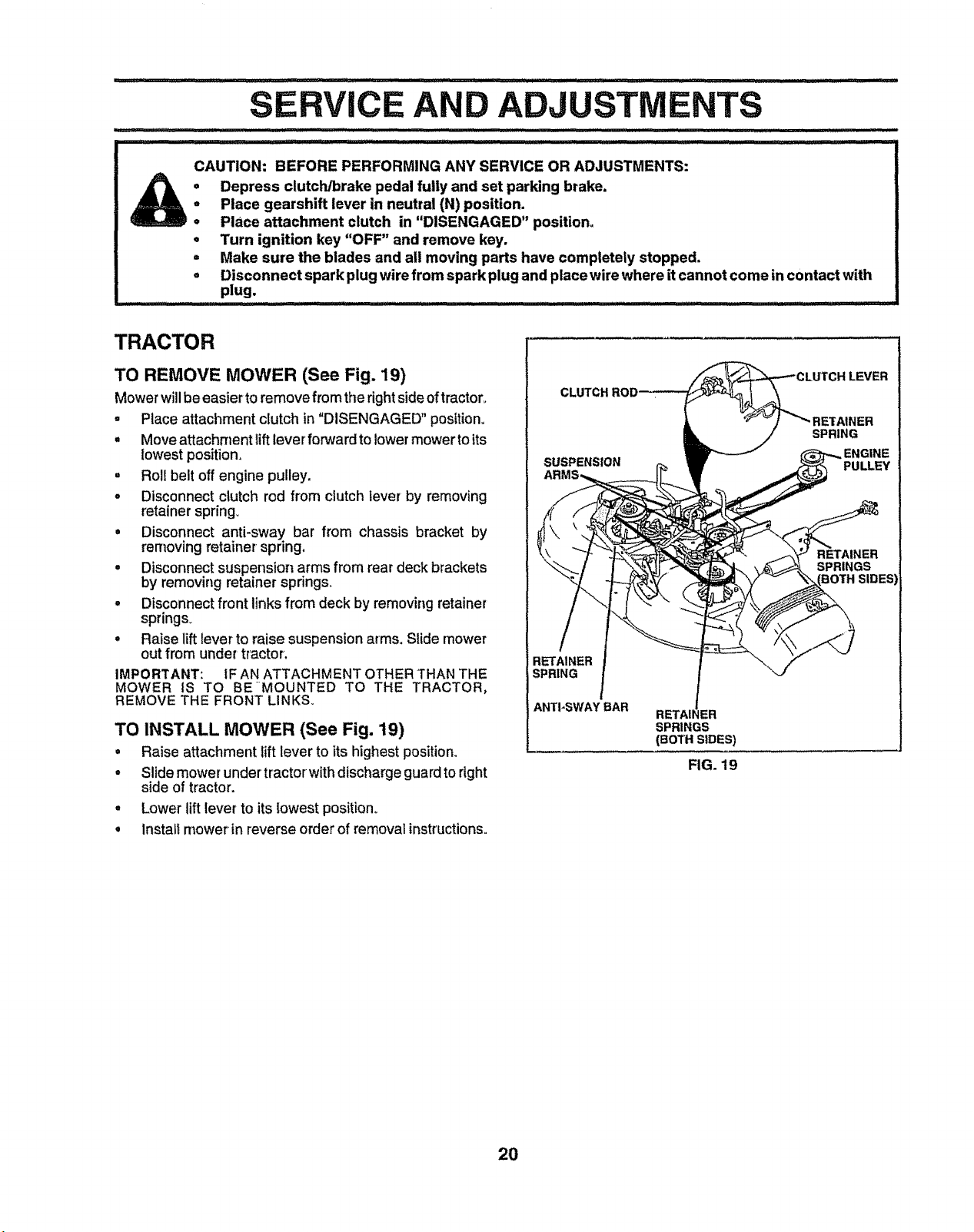
TO REMOVE MOWER (See Fig. 19)
Mower willbe easier to remove from the rightsideoftractor_
• Race attachment clutch in "DISENGAGED" position°
, Move attachment liftlever forward to lowermowerto its
lowest position_
• Roll belt off engine pulley,
o Disconnect clutch rod from clutch lever by removing
retainer springy
• Disconnect anti-sway bar from chassis bracket by
removing retainer spring,
• Disconnect suspension arms from rear deck brackets
by removing retainer springs°
° Disconnect front links from deck by removing retainer
springs_
° Raise lift lever to raise suspension arms, Slide mower
out from under tractor,
IMPORTANT: IF AN ATTACHMENT OTHER THAN THE
MOWER IS TO BE-MOUNTED TO THE TRACTOR,
REMOVE THE FRONT LINKS.
TO INSTALL MOWER (See Fig. 19)
• Raise attachment lift lever to its highest position,
° Slide mower undertractor with discharge guard to right
side of tractor.
• Lower lift lever to its lowest position°
° Instalt mower in reverse order of removal instructions°
CLUTCH
SUSPENSION
:H LEVER
|ER
SPRING
PULLEY
RETAINER
SPRINGS
RETAINER
SPRING
ANTI-SWAY BAR
RETAI_
SPRINGS
(BOTH SIDES)
FIG. 19
2O
ERVICE AND ADJUSTMENTS
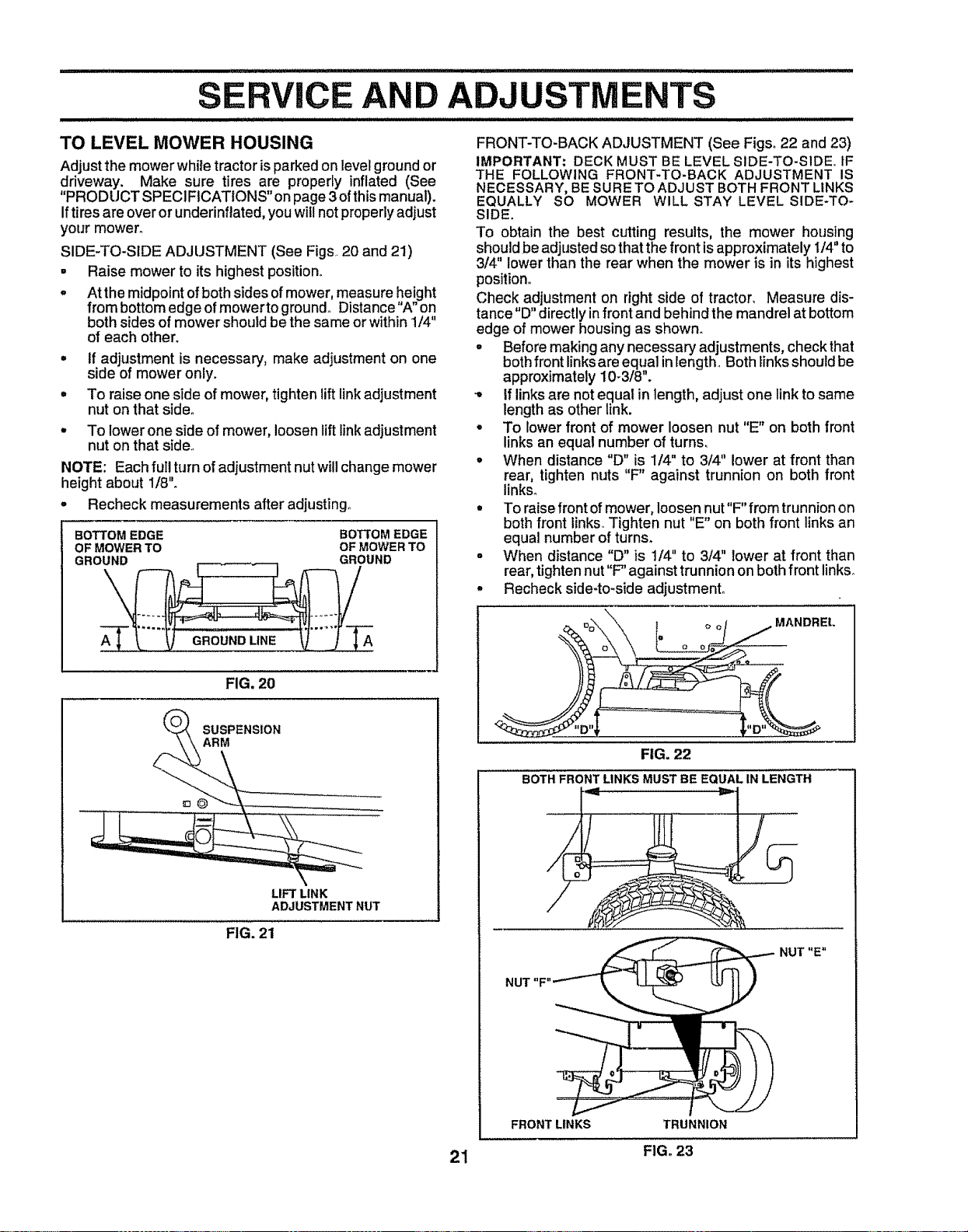
TO LEVEL MOWER HOUSING
Adjust the mower while tractor isparked on level ground or
driveway. Make sure tires are properly inflated (See
"PRODUCT SPECIFICATIONS" on page 3of this manual).
Iftires are over or underinflated, you will not properly adjust
your mower°
SIDE-TO-SIDE ADJUSTMENT (See Figs 20 and 21)
• Raise mower to its highest position.
= At the midpoint of both sides of mower, measure height
from bottom edge of mowerto ground° Distance "A" on
both sides of mower should be the same or within 1/4"
of each other.
° If adjustment is necessary, make adjustment on one
side of mower only.
° To raise one side of mower, tighten lift link adjustment
nut on that side°
To lower one side of mower, loosen lift link adjustment
nut on that side..
NOTE: Each ful! turn of adjustment nut will change mower
height about 1/8'L
° Recheck measurements after adjusting..
BOTTOM EDGE BOTTOM EDGE
OF MOWER TO OF MOWER TO
GROUND GROUND
GROUND LINE A
FIG. 20
LIFT LINK
ADJUSTMENT NUT
FIG. 21
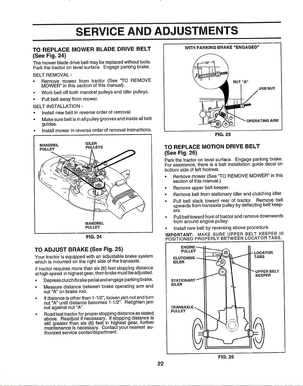
FRONT-TO-BACK ADJUSTMENT (See Figs° 22 and 23)
IMPORTANT: DECK MUST BE LEVEL SIDE-TO-SIDE.. tF
THE FOLLOWING FRONT-TO-BACK ADJUSTMENT IS
NECESSARY, BE SURETO ADJUST BOTH FRONT LINKS
EQUALLY SO MOWER WILL STAY LEVEL SIDE-TO-
SIDE.
To obtain the best cutting results, the mower housing
should be adjusted so that the front is approximately 1/4" to
3/4" lower than the rear when the mower is in its highest
position°
Check adjustment on right side of tractor, Measure dis-
tance "D" directly in front and behind the mandrel at bottom
edge of mower housing as shown.
° Before making any necessary adjustments, checkthat
both front links are equal in length. Both _inksshould be
approximately 10-3/8".
-, If links are not equal in length, adjust one Ilnk to same
length as other link.
° To lower front of mower loosen nut "E" on both front
links an equal number of turns.
, When distance "D" is 1/4" to 3/4" lower at front than
rear, tighten nuts "F" against trunnion on both front
links°
• To raise front of mower, loosen nut"F" from trunnion on
both front links_Tighten nut "E" on both front links an
equal number of turns.
• When distance "D" is 1/4" to 3/4" lower at front than
rear, tighten nut "F" against trunnion on both front links°
° Recheckside-to-side adjustment°
= o_\\\ _= o o! .,..MANDREL
0 0 0
FIG. 22
BOTH FRONT LINKS MUST BE EQUAL IN LENGTH
u
NUT "E"
NUT "F"
FRONT LINKS TRUNNION
21 FIG. 23
TO REPLACE MOWER BLADE DRIVE BELT
(See Fig. 24)
The mower blade drive belt may be replaced withouttools.
Park the tractor on level surface.. Engage parking brake.
BELT REMOVAL -
* Remove mower from tractor (See "TO REMOVE
MOWER" in this section of this manual).
o Work belt off both mandrel pulleys and idler pulleys°
, Pull belt away from mower..
BELT iNSTALLATION -
° Install new belt in reverse order of removal.
. Makesurebeltisinallputleygroovesandinsideallbelt
guides.
= Install mower in reverse order of removal instructions.
MANDREL IDLER
PULLEY PULLEYS
MANDREL
PULLEY
FIG. 24
TO ADJUST BRAKE (See Fig. 25)
Your tractor is equipped with an adjustable brake system
which is mounted on the rightside of the transaxle.
tftractor requires more than six (6) feet stopping distance
at high speed in highest gear,then brake must be adjustedo
• Depress clutch/brake pedalandengage parking brake.
° Measure distance between brake operating arm and
nut "A" on brake rod.
tf distance is other than 1-1/2", loosen jam nut and turn
nut "A" until distance becomes 1-1/2'L Retighten jam
nut against nut "A",
Road test tractor for proper stopping distance as stated
above.. Readjust if necessary, if stopping distance is
still greater than six (6) feet in highest gear', further
maintenance is necessary.. Contact your nearest au-.
thorized service center/department.
WITHPARKINGBRAKE "ENGAGED"
NUT "A"
_JAM NUT
RG. 25
22
TO REPLACE MOTION DRIVE BELT
(See Fig. 26)
Park the tractor on level surface_ Engage parking brake,,
For assistance, there is a belt installationguide decal on
bottom side of left footrest.
• Remove mower' (See 'q'O REMOVE MOWER" in this
section of this manuaL)
° Remove upper belt keeper.
° Remove belt from stationary idler and clutching idler.
, Pull belt slack toward rear of tractoL Remove belt
upwards from transaxle pultey by deflecting belt keep-
ers,
° Pull belt toward front of tractor' and remove downwards
from around engine pulley_
° Install new belt by reversing above procedure°
IMPORTANT: MAKE SURE UPPER BELT KEEPER IS
POSITIONED PROPERLY BETWEEN LOCATOR TABS,
ENGINE,-,,_. A Ii
PULLEY I_-_t _=" _._-.-LOCATOR
CLUTCHING _.,,_._ {I TABS
II ...._.(o),_ | it-- UPPERBELT
_ | I! KEEPER
STATIONARY"'-!1 I | II
II !111
TRANSAXLE-_ il _ II
FIG. 26
ERVICE AND
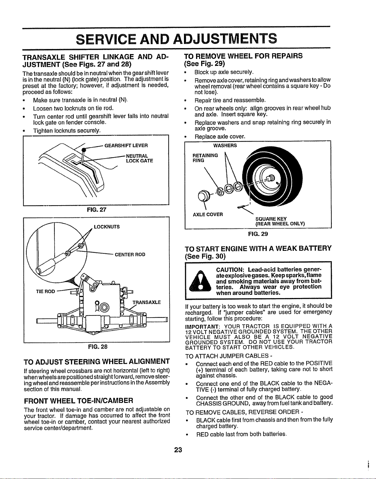
TRANSAXLE SHIFTER LINKAGE AND AD-
JUSTMENT (See Figs. 27 and 28)
The transaxle should be in neutral when the gear shift lever
is in the neutral (N) (lock gate) position. The adjustment is
preset at the factory; however, if adjustment is needed,
proceed as follows:
° Make sure transaxle is in neutral (N).
• Loosen two locknuts on tie rod°
° Turn center rod until gearshift lever falls into neutral
lock gate on fender console,,
Tighten Iocknuts securely.
FIG. 27
f
\
TIE ROD
TS
CENTER ROD
FIG. 28
TO ADJUST STEERING WHEEL ALIGNMENT
tf steering wheel crossbars are not horizontal (left to right)
when wheels are positioned straight forward, remove steer-
ing wheel and reassemble per instructions in the Assembly
section of this manual,
FRONT WHEEL TOE-IN/CAMBER
The front wheel toe-in and camber are not adjustabte on
your tractor. If damage has occurred to affect the front
wheel toe-in or camber, contact your nearest authorized
service centeridepartmenL
ADJUSTMENTS
........... i i NlllIJJ .........
TO REMOVE WHEEL FOR REPAIRS
(See Fig. 29)
° Block up axle securely,
• Remove axle cover, retaining ringand washersto allow
wheel removal (rear wheel contains a square key - Do
not lose).
° Repair tire and reassemble.
° On rear wheels onfy: align grooves in rear wheel hub
and axleo Insert square key.
. Replace washers and snap retaining ring securely in
axle groove.
Replace axle cover.
WASHERS
RETAINING
RING
AXLE COVER
SQUARE KEY
(REAR WHEEL ONLY)
FIG. 29
TO START ENGINE WITH A WEAK BATTERY
(See Fig. 30)
i ill ....................................
l& CAUTION: Lead-acid batteries gener-
ate explosive gases. Keep sparks, flame
and smoking materials away from bat-
teries. Always wear eye protection
when around batteries. ..................
................. , , ,, ,,,,,,,
if your battery is too weak to start the engine, it should be
recharged, tf "jumper cables" are used for emergency
starting, follow this procedure:
IMPORTANT: YOUR TRACTOR IS EQUIPPED WITH A
12 VOLT NEGATIVE GROUNDED SYSTEM. THE OTHER
VEHICLE MUST ALSO BE A 12 VOLT NEGATIVE
GROUNDED SYSTEM. DO NOT USE YOUR TRACTOR
BATTERY TO START OTHER VEHICLES°
TO ATTACH JUMPER CABLES -
• Connect each end of the RED cable to the POSITIVE
(+) terminal of each battery, taking care not to short
against chassis.
° Connect one end of the BLACK cable to the NEGA-
TiVE (-) terminal of fully charged battery_
• Connect the other end of the BLACK cable to good
CHASSIS GROUND, away from fuel tank and battery.
TO REMOVE CABLES, REVERSE ORDER -
° BLACK cable first from chassis and then from the fully
charged battery_
• RED cable last from both batteries.
23
......... jllllllll iii iiiii iii _1111iiiiii ............. ........................ :-- :: .... ,.............................................
POSITIVE TERMINAL
iCE AND ADJUSTMENTS
iiiiiiiij ilUlllllllllliii iiiiiiiiiiiiiiiiii iiiiiiiiii,r iiii iiiiiiii ,i ........... :.............. ::
NEGATIVETERMINAL TO REPLACE FUSE
Replace with 30 amp automotive-type plug-in fuse, The
fuse holder is located behind the dash,,
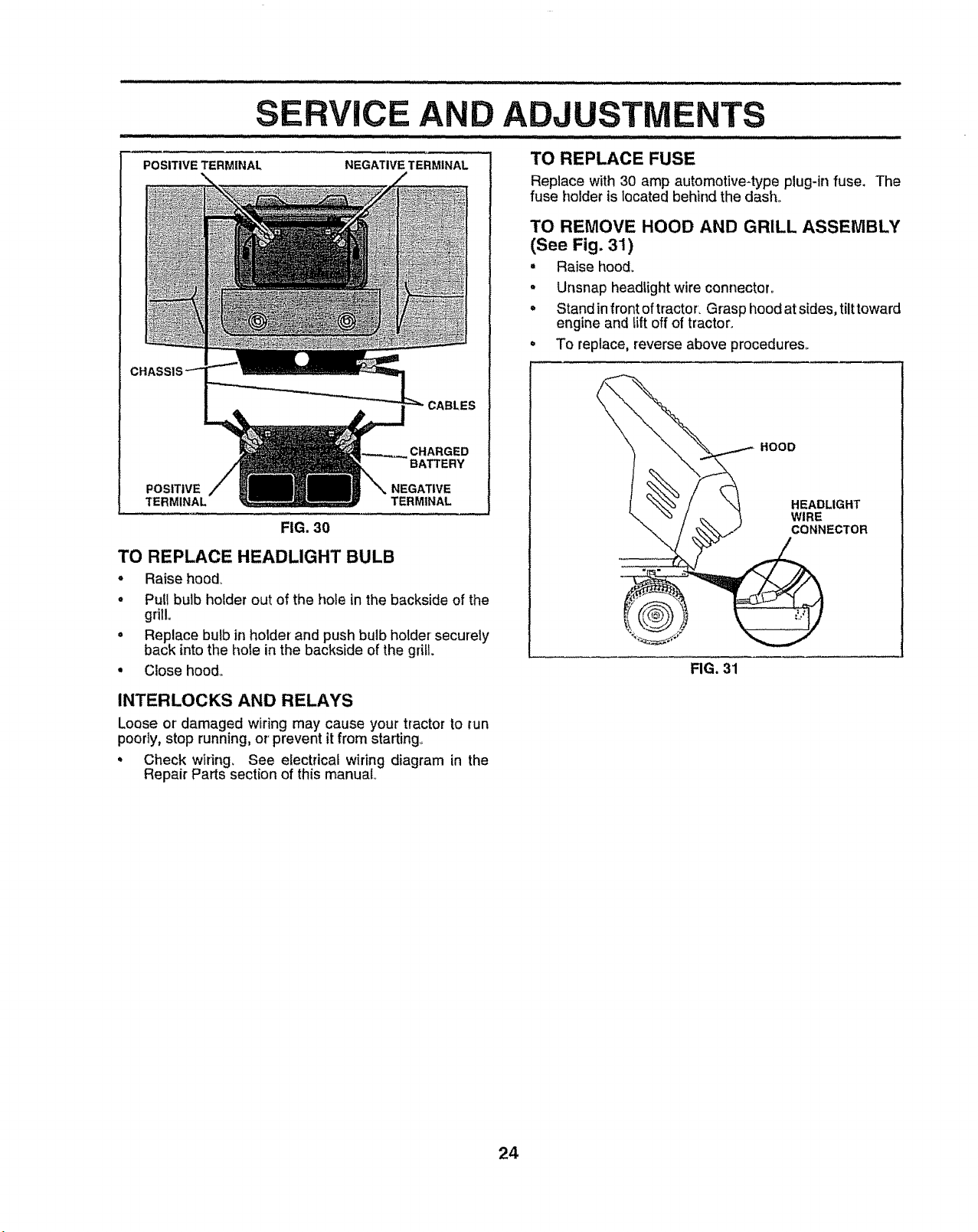
TO REMOVE HOOD AND GRILL ASSEMBLY
(See Fig. 31)
• Raise hood_
• Unsnap headtightwire connector°
• Stand infront of tractor. Grasp hood at sides, tilt toward
engine and tiffoff of tractor.
° To replace, reverse above procedures_
CABLES
CHARGED
BATTERY
POSITIVE NEGATIVE
TERI TERMINAL
FIG, 30
TO REPLACE HEADLIGHT BULB
. Raise hood_
• Pull bulb holder out of the hole in the backside of the
grill°
• Replace bulb in holder and push bulb holder securely
back into the hole in the backside of the grill.
° Close hood_
INTERLOCKS AND RELAYS
Loose or' damaged wiring may cause your tractor to _un
poorly, stop running, or' prevent it from starting.
= Check wiring. See electrical wiring diagram in the
Repair Parts section of this manual
__ HOOD
N TR
FIG. 31
24
,111,i,1,1,,,i,1,,i,i,i1,111111,,i,i,ii ii i , i, i,,, ii, ,I,ILI
SERVICE AND ADJUSTM
ENGINE
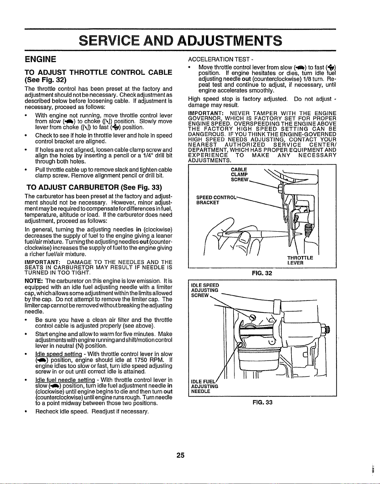
TO ADJUST THROTTLE CONTROL CABLE
(See Fig. 32)
The throttle control has been preset at the factoR/and
adjustment should not be necessary. Check adjustment as
described below before loosening cable, tf adjustment is
necessary, proceed as follows:
= With engine not running, move throttle control lever
from slow (,e_) to choke (N) position_ Slowly move
lever from choke (i\I) to fast (.€_) position°
. Check to see if hole in throttle lever and hole in speed
control bracket are aligned°
° If holes are not aligned, loosencable clamp screw and
align the holes by inserting a pencil or a 1/4" drill bit
through both holes.
• Pull throttle cable up to remove slack and tighten cable
clamp screw. Remove alignment pencil or drill bit.,
TO ADJUST CARBURETOR (See Fig. 33)
The carburetor has been preset at the factory and adjust-
ment should not be necessary. However, minor adjust-
ment may be required to compensate for differences in fuel,
temperature, altitude or loado Ifthe carburetor does need
adjustment, proceed as follows:
In general, turning the adjusting needles in (clockwise)
decreases the supply of fuel to the engine giving a leaner
fuel/air mixture° Turning the adjusting needles out (counter-
clockwise) increases the supply of fuel to the engine giving
a richer fuel/air mixture.
IMPORTANT; DAMAGE TO THE NEEDLES AND THE
SEATS IN CARBURETOR MAY RESULT IF NEEDLE IS
TURNED IN TOO TIGHT,.
NOTE: The carburetor on this engine is low emission. It is
equipped with an idle fuel adjusting needie with a limiter
cap, which allows some adjustment within the limitsallowed
by the cap° Do not attempt to remove the limiter cap° The
limiter cap cannot beremoved without breaking the adjusting
needleo
° Be sure you have a clean air filter and the throttle
control cable is adjusted property (see above).
. Start engine and allow to warm for five minutes., Make
adjustments with engine running andshift/motion control
lever in neutral (N) position°
• Idle speed setting - With throttle control lever in slow
(,at,) position, engine should idle at 1750 RPM. If
engine idles too slow or fast, turn idle speed adjusting
screw in or out until correct idle is attained.
• Idle fuel needle settinq - With throttlecontrol lever in
slow (,_lb) position, turn idle fuel adjustment needle in
(clockwise) until engine begins to die and then turn out
(counterclockwise) until engine runs rough. Turn needle
to a point midway between those two positions.
• Recheck idle speed° Readjust if necessary.,
ACCELERATION TEST -
° Move throttle control lever from slow (.e!,) to fast (,_)
position. If engine hesitates or dies, turn idle fuel
adjusting needle out (counterclockwise) 1/8 turn.. Re-
peat test and continue to adjust, if necessary, until
engine accelerates smoothly.
High speed stop is factory adjusted. Do not adjust -
damage may result°
IMPORTANT: NEVER TAMPER WITH THE ENGINE
GOVERNOR, WHICH IS FACTORY SET FOR PROPER
ENGINE SPEED. OVERSPEEDING THE ENGINE ABOVE
THE FACTORY HIGH SPEED SETTING CAN BE
DANGEROUS,, tF YOU THINK THE ENGINE-GOVERNED
HIGH SPEED NEEDS ADJUSTING, CONTACT YOUR
NEAREST AUTHORIZED SERVICE CENTER/
DEPARTMENT, WHICH HAS PROPER EQUIPMENT AND
EXPERIENCE TO MAKE ANY NECESSARY
ADJUSTMENTS,
CABLE
CLAMP
SPEED
BRACKET
FIG. 32
THROTTLE
LEVER
IDLE SPEED
ADJUSTING
-,------
ADJUSTING
NEEDLE
FIG. 33
25
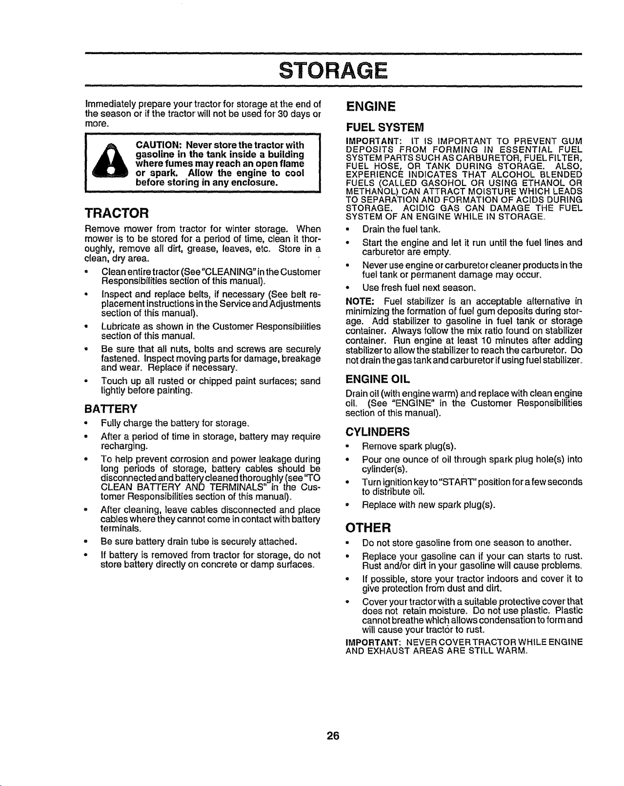
STORAGE
.... i i,H ................
Immediately prepare your tractor for Storage at the end of
the season or if the tractor will not be used for' 30 days or
more°
CAUTION: Never store the tractor with
gasoline in the tank inside a building I
where fumes may reach an open flame |
or spark. Allow the engine to cool |
before storing in any enclosure.
TRACTOR
Remove mower from tractor for winter storage. When
mower is to be stored for a period of time, clean it thor-
oughly, remove all dirt, grease, leaves, etco Store in a
clean, dry area.
° Clean entire tractor (See"CLEANING" inthe Customer
Responsibilitles section of this manual)°
• Inspect and replace belts, if necessary (See belt re-
placement instructions in the Service and Adjustments
section of this manual)°
° Lubricate as shown in the Customer Responsibilities
section of this manual.
. Be sure that all nuts, bolts and screws are securely
fastened. Inspect moving parts for damage, breakage
and wear. Replace if necessary_
° Touch up all rusted or chipped paint surfaces; sand
lightly before painting.
BATTERY
. Fulty charge the battery for storage.
• After a period of time in storage, battery may require
recharging.
° To help prevent corrosion and power leakage during
long periods of storage, battery cables should be
disconnected and batteP$cleaned thoroughly (see'_O
CLEAN BATTERY AND TERMINALS in the Cu -
tomer Responsibilities section of this manual),
° After cleaning, leave cables disconnected and place
cables where they cannot come in contact with battery
terminals.
° Be sure battery drain tube is securely attached.
° If battery Is removed from tractor for storage, do not
store battery directly on concrete or damp surfaces,
ENGINE
FUEL SYSTEM
IMPORTANT: tT IS IMPORTANT TO PREVENT GUM
DEPOSITS FROM FORMING IN ESSENTIAL FUEL
SYSTEM PARTS SUCH AS CARBURETOR, FUEL FILTER,
FUEL HOSE, OR TANK DURING STORAGE. ALSO,
EXPERIENCE INDICATES THAT ALCOHOL BLENDED
FUELS (CALLED GASOHOL OR USING ETHANOL OR
METHANOL) CAN ATTRACT MOISTURE WHICH LEADS
TO SEPARATION AND FORMATION OF ACIDS DURING
STORAGE, ACIDIC GAS CAN DAMAGE THE FUEL
SYSTEM OF AN ENGINE WHILE IN STORAGE,,
Drain the fuel tank.
t
o
Start the engine and let it run until the fuel lines and
carburetor are empty.
Never use engine or carburetor cleaner products in the
fuel tank or permanent damage may occur',
Use fresh fuel next season.
NOTE: Fuel stabilizer is an acceptable alternative in
minimizing the formation of fuel gum deposits during stor-
age. Add stabilizer to gasoline in fuel tank or storage
container. Always follow the mix ratio found on stabilizer
container. Run engine at least 10 minutes after adding
stabilizer to al!owthe stabilizer to reach the carburetor. Do
not drainthe gas tank and carburetor if using fuel stabilizer,
ENGINE OIL
Drain oil (with engine warm) and replace with clean engine
oil (See "ENGINE" in the Customer Responsibilities
section of this manual).
CYLINDERS
° Remove spark plug(s).
. Pour one ounce of oil through spark ptug hole(s) into
cylinder(s)o
. Turn ignition key to"START" position for a few seconds
to distribute oil.
° Replace with new spark plug(s).
OTHER
• Do not store gasoline from one season to another.
= Replace your gasoline can if your can starts to rust,
Rust andfor dirt in your gasoline will cause problems,
° If possible, store your tractor indoors and cover it to
give protection from dust and dirt,
• Cover your tractor with a suitable protective cover that
does not retain moisture. Do not use plastic. Plastic
cannot breathe which allows condensation to form and
will cause your tractor to rust.
IMPORTANT: NEVER COVER TRACTOR WHILE ENGINE
AND EXHAUST AREAS ARE STILL WARM°
26

................ i,i, ill,,,ii ,i i
.......................... illl
TROUB
NTS
PROBLEM
, i i lllllll ........
Will not start
IIIIIIH I I II Ill Illlllllll
Hard to start
H
Engine will not turn over
Engine clicks but will not
start
Loss of power
Excessive vibration
CAUSE
1., Out of rue!,
2. Engine not"CHOKED"properly,
3. Engine flooded,
4. Bad spark plug.
5. Dirty air filter,
64 Dirty fuel filter,
7o Water in fuel
8o Loose or damaged wiring.
9. Carburetor out of adjustment.
10o Engine valves out of adjustment-
ii
1., Dirty air filter,.
2o Bad spark plug,
3. Weak or dead battery,
4, Dirty fue! filter,
5o Stale or dirty fuel,
6. Loose or damaged widng.
7. Carburetor out of adjustment
8. Engine valves out of adjustment
CORRECTION
1, RI! fuel tank
2,, See "TO START ENGINE" In Operation section,
3. Wait several minutes before attempting to start°
4. Replace spark plug,.
5. Clean/replace aErfitter,
6, Replace fuel filter,
7, Drain fuel tank and carburetor, refill tank with fresh
gasoline and replace fuet filter,
8 Check all widng,
9. See "To Adjust Carburetor" in Service Adjustments
section.
10_ Contact an authorized service center!department,
1 Clean/replace air filter
2. Replace spark plug_
3. Recharge or replace battery
4. Replace fuel filter,
5 Drain fuel tank and refill with fresh gasoline°
6, Check all wtdng.
7, See "TOAdjust Carburetor" in Service Adjustments
section,,
8, Contact an authorized service center/department.,
1o Clutch/brake pedal not depressed,
2,, Attachment clutch Is engaged
3. Weak or dead battery,
4. Blown fuse,
5_ Corroded battery terminals.
6, Loose or damaged widng
7, Faulty ignition switch,
8 Faulty solenoid or starter°
9, Faulty operator presence switch(as).
1, Weak or dead battery_
2. Corrodedbatteryterminals
3, Looseor damagedwidng_
4, Faultysolenoid or starter.
1. Depress clutct.J'orakepedal.
2_ Disengage attachment clutch,
3, Recharge or replace battery,
4., Replace fuse,
5o Clean batter] terminals
6, Check all wiring
7, Check/replace ignition switch,
8, Check/replace solenold or starter,
9, Contact an authodzed service centerldepartment,,
1o Recharge or replace battery°
2., Clean battery terminals,,
3_ Check all wiring,,
4. Check/replace solenoid or starter.
1 Cutting too much grass/too fast
2, Throttle in "CHOKE" position.
3. Build-up of grass, leaves and trash under mower.
4, Dirty air filter..
5 Low otl levelldtrty oll,
6. Faulty spark plug,
7 Dirty fuel filter,,
8. Stale or dirty fuel,
9. Water in fuel.
10, Spark plug wire Ioose_
11,. Dirty engine air screentfins
12. Dirty/clogged muffler.,
13. Loose or damaged widng,,
14. Carburetor out of adjustment.
15, Engine valves out of adjustment,
1. Worn, bent or loose blade
2_ Bent blade mandrel.
3. Looseldamaged part(s)_
I Set tn "Higher Cut" position/reduce speed
2, Adjust throttle control
3 Clean underside of mower housing.
4. Clean/replace air filter,
5 Check oil leveVchange oiL,
6. Clean and regap or change spark plug
7, Replace fuel filter.
8. Drain fuel tank and refill with fresh gasoline,
9, Drain fuel tank and carburetor, refifltank with fresh
gasoline and replace fuel filter,,
I0_ Connect and tighten spark plug wire.
1 t. Clean engine air screen/fins.
12. Clean!replace muffler,
13, Check all wiring,
14_, See "To Adjust Carburetor" In Service Adiustments
section°
15 Contact an authorized service center/department.
1.. Replace bEade Tighten blade bolt,
2. Replace blade mandrel.
3., Tighten loose part(s) Replace damaged parts
27
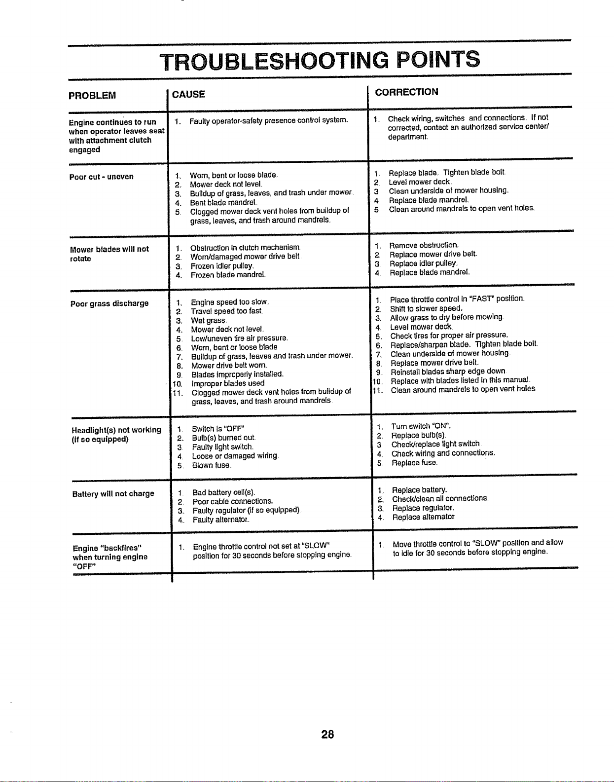
iii r,,i,Hi illlll .................... ill i,,,,,
TROUBLESHOOTING POINTS
PROBLEM
i
Engine continues to run
when operator leaves seat
with attachment clutch
engaged
Poor cut - uneven
Mower blades will not
rotate
Poor grass discharge
Headlight(s) not working
(if so equipped)
Battery will not charge
Engine "backfires"
when turning engine
"OFF"
CAUSE
iii I 1111111 iii1[11111111 iiiiii II IIIIIIIII II [11 I IIII III II1'1 :
1. Faulty operator-safety presence controt system..
1o Worn, bent or loose blade.
2_ Mower deck not level.
3. Buitdupof grass, leaves, and trash under mower,
4. Bent b_ade mandrel
5. Clogged mower deck vent holes from buildup of
grass, leaves, and trash around mandrels.
1. Obstructionin clutchmechanism.
2, Worn/damagedmower drivebelt,
3, Frozenidlerpuliey,
4. Frozenblade mandrel,
Io Engine speed toosIow.
2, Travel speed too fast
3o Wet grass.
4o Mower deck not level,
5. Lowluneven tire air pressure,
6 Worn, bent or loose blade
7. Buildup of grass, leaves and trash under mowerv
8o Mower ddve belt worn.
9. Blades improperly installed,,
10, Improper blades used,
t 1. Clogged mower deck vent holes from bulidup of
grass, leaves, and trash around mandrels,
I Switch is "OFF"
2o Bulb(s) bumedout.
3 Faulty tight switch
4_ Loose or damaged wiring.
5, Blown fuse,
1 Bad battery cell(s).
2, Poet cable connections,,
3,. Faulty regulator (if so equipped).
4,. Faulty alternator,.
1. Engine throlUe control not set at "SLOW"
position for 30 seconds before slopping engine
CORRECTION
1. Check wiring, switches and connections. If not
corrected, contaot an authorized service center/
department.
1, Replace blade_ Tighten blade bolt.,
2, Level mower deck.
3 Clean underside of mower housing,,
4 Replace b_ade mandrel,
5, Clean around mandrels to open vent holes.
1. Remove obstruction..
2 Replace mower drive belt.
3 Replace idler pulley.
4,, Replace blade mandrel
1_ Place throttle control In =FAST" position.
2, Shift to slower speed.
3, Allow grass to dry before mowing_
4 Level mower deck,
5, Cheek tires for proper air pressure,
6 Replace/sharpen bTadeo Tighten blade bolt.
7. Clean underside of mower housing,
B, Replace mower drive bait°
9,. Reinstall blades sharp edge down
10, Replace with blades listed [n this manual,
11. Clean around mandrels to open vent holes.
1, Turn switch "ON".
2, Replace bulb(s),
3 Check/replace light switch
4_ Check wIdng and connections,
5, Replace fuse,
1, Replace battery°
2, Check/clean all connect_ns
34 Replace regulator.
4, Replace alternator
Move throttle control to "SLOW" position and allow
to idle for 30 seconds before stopping engine.
28
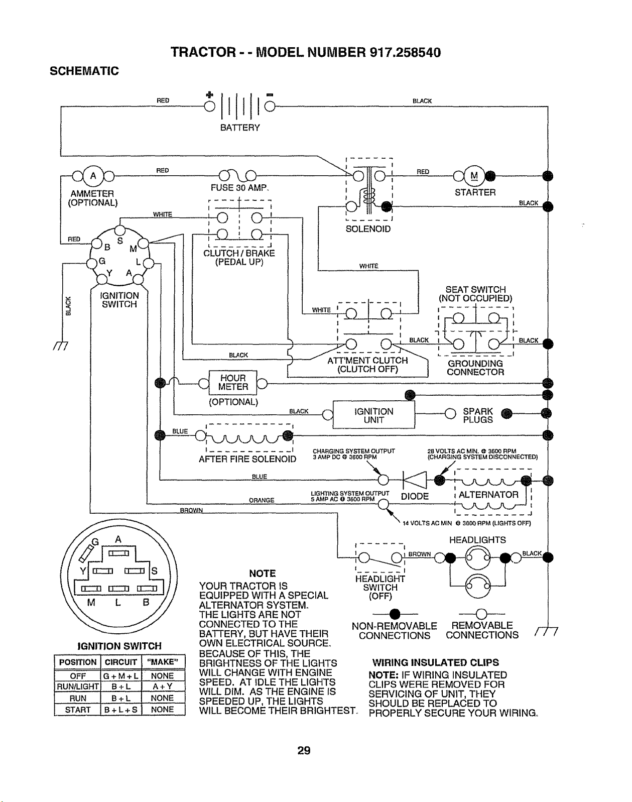
TRACTOR - - MODEL NUMBER 917.258540
SCHEMATIC
RED
BATTERY
BLACK
-e 9
AMMETER
(OPTIONAL)
RED
FUSE30 AMP..
wHrfE
! 1
t 1
RED
STARTER
BLACK
I
IGNITION
SWITCH
M
IGNITION SWITCH
POSITION CIRCUIT "MAKE"
....... j , ,,, ,, ......
OFF G + M + L NONE
RUN/LIGHT, B + L A + Y
RUN B + L NONE
START B + L + S
I _ SOLENOID
L J
CLUTCH1 BRAKE
(PEDAL UP) WHITE
,--,I- SEATSW,TCH
(NOT OCCUPIED)
1 - I I .... t 1
J I I .....
"3 .... F-
, .......,
", __ .BLACKf._METERHOURJ_ ..........._' ATTT'(C-LMET_C_H_OL'Ui_'_ " " -'---" -"--'CONNECToRGROUNDING
(OPTIONAL)
sLAcK _._ IGNITION t_L----.-- _ SPARK
UNIT PLUGS
D
6L
IF
t .... I
AFTER FIRE SOLENOID
BLUE
BROWN
ORANGE
NOTE
YOUR TRACTOR IS
CHARGING SySTF_M OUTPLr]"
3 AMP DO {_ ,3600 RPM
b
b
,=
EQUIPPED WITH A SPECIAL
ALTERNATOR SYSTEM.
THE LIGHTS ARE NOT
CONNECTED TO THE
BATTERY, BUT HAVE THEIR
OWN ELECTRICAL SOURCE°
BECAUSE OF THIS, THE
6
,q
BRIGHTNESS OF THE LIGHTS
WILL CHANGE WITH ENGINE
SPEED. AT IDLE THE LIGHTS
WILL DIM. AS THE ENGINE IS
SPEEDED UP, THE LIGHTS
2B VOLTS AC MIN, @ 3500 RPM
(CHARGING SYSTEM DISCONNECTED)
NONE
(OFF)
• ©
NON-REMOVABLE REMOVABLE
CONNECTIONS CONNECTIONS
/-2
WIRING INSULATED CLIPS
NOTE: IF WIRING INSULATED
CLIPS WERE REMOVED FOR
SERVICING OF UNIT, THEY
SHOULD BE REPLACED TO
WILL BECOME THEIR BRIGHTEST._ PROPERLY SECURE YOUR WIRING,.
29

REPAIR PARTS
TRACTOR -- MODEL NUMBER 917,258540
ELECTRICAL
19
32
26
t
19 I _,
i fi
t t _11
t iI
f i t
It
It
It
tt
l t tt
I t tt
$ t tt
1 l
I t
t t
t t
t
t
f
l
|
t
t
I
I
I
!
6
I
/
/
/
#
t
#
3O
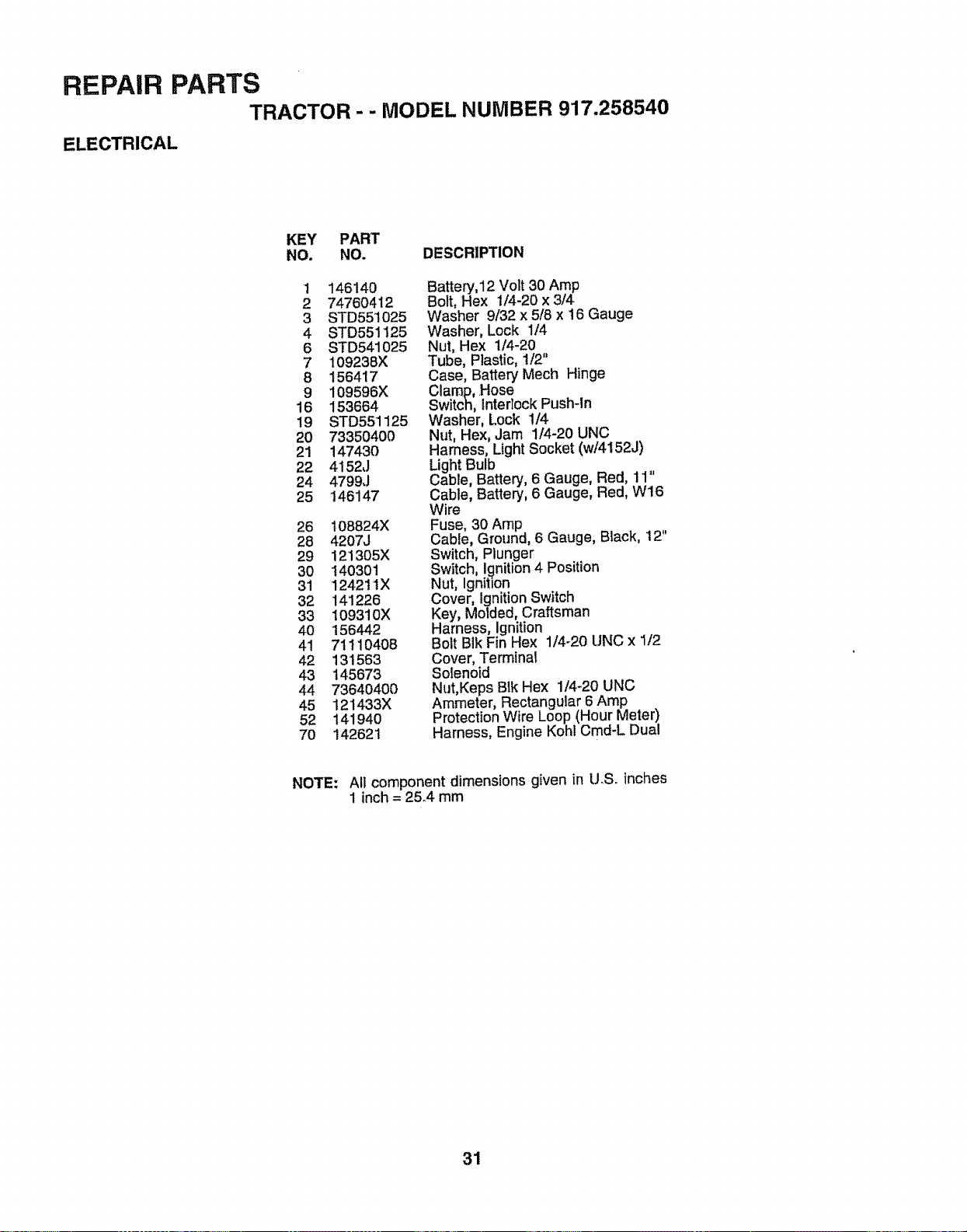
REPAIR PARTS
TRACTOR - - MODEL NUMBER 917.258540
ELECTRICAL
KEY PART
NO. NO. DESCRIPTION
1 146140
2 74760412
3 STD551025
4 STD551125
6 STD541025
7 109238X
8 156417
9 109596X
16 153664
19 STD551125
20 733504O0
21 147430
22 4152J
24 4799J
25 146147
26 I08824X
28 4207J
29 121305X
30 140301
31 124211X
32 141226
33 109310X
40 156442
41 71110408
42 131563
43 145673
44 73640400
45 121433X
52 141940
7O 142621
Battery,12 Volt 30 Amp
Bolt, Hex t/4-20 x 3/4
Washer 9/32 x 5/8 x 16 Gauge
Washer, Lock 1/4
Nut, Hex 1/4-20
Tube, Plastic, 1/2"
Case, Battery Mech Hinge
Clamp, .Hose
Switch, Interlock Push-In
Washer, Lock 1/4
Nut, Hex, Jam 1/4-20 UNC
Harness, Light Socket (w/4152J)
Light Bulb ,,
Cable, Battery, 6 Gauge, Red, 11
Cable, Battery, 6 Gauge, Red, W16
Wire
Fuse, 30 Amp
Cable, Ground, 6 Gauge, Black, 12"
Switch, Plunger
Switch, I_nition 4 Position
Nut, Ignihon
Cover, Ignition Switch
Key, Molded, Craftsman
Harness, Ignition
Bolt BIk Fin Hex 1/4o20 UNC x 1/2
Cover, Terminal
Solenoid
Nut,Keps B]k Hex 1/4-20 UNC
Ammeter, Rectangular 6 Amp
Protection Wire Loop (Hour Meter)
Harness, Engine Kohl Cmd-L Dual
NOTE: All component dimensions given in U_S_tnches
1 inch = 25_4mm
31
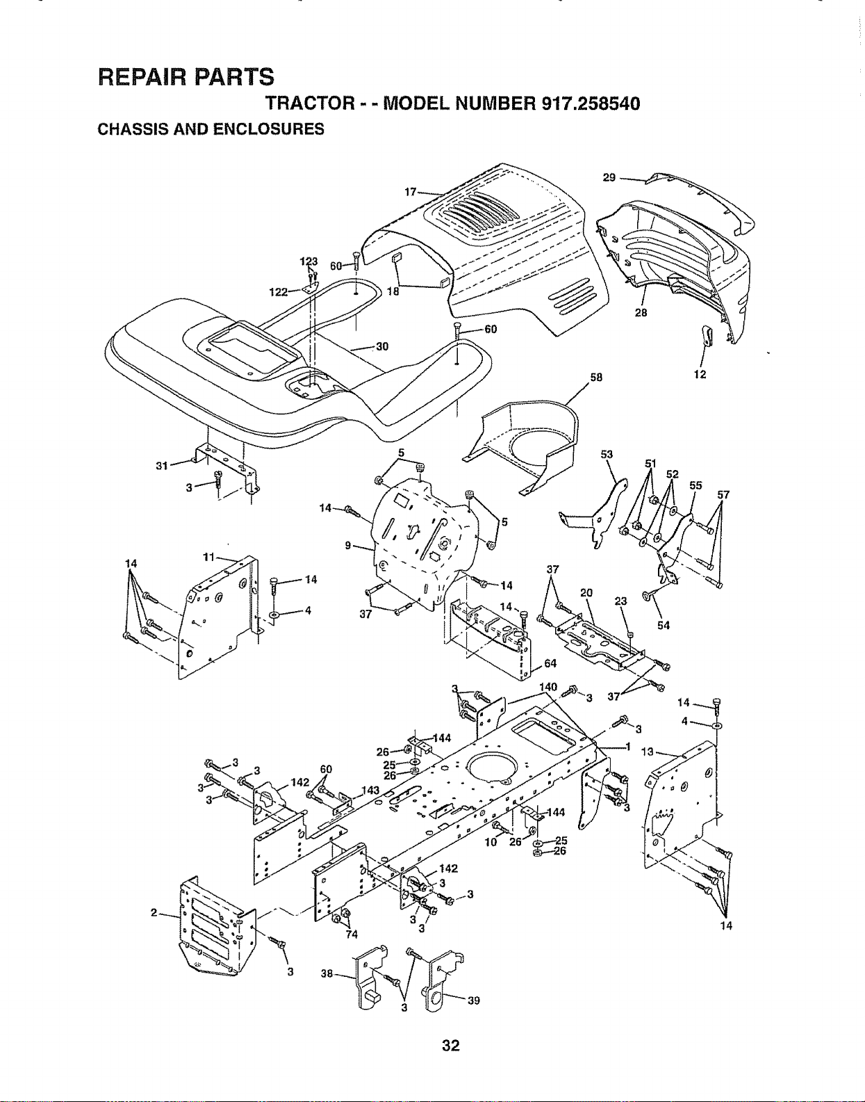
REPAIR PARTS
TRACTOR .-- MODEL NUMBER 917.258540
CHASSIS AND ENCLOSURES
28
58 12
31
60
10 26'
3 /
74 3
38_ 39
14
32
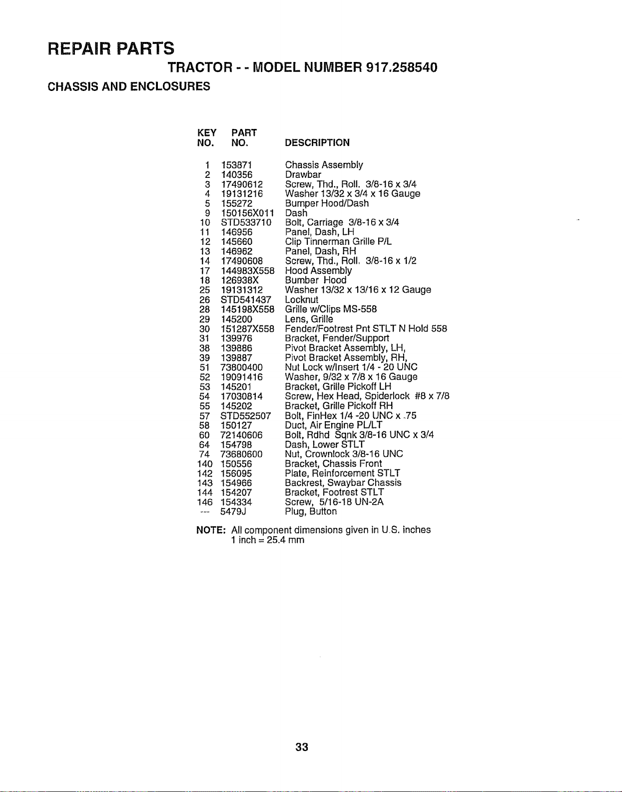
REPAIR PARTS
TRACTOR - - MODEL NUMBER 917.258540
CHASSIS AND ENCLOSURES
KEY PART
NO. NOo DESCRIPTION
1 153871
2 140356
3 17490612
4 19131216
5 155272
9 150t56X011
10 STD533710
11 146956
12 145660
13 146962
14 17490608
17 144983X558
18 126938X
25 19131312
26 STD541437
28 145198X558
29 145200
30 151287X558
31 139976
38 139886
39 139887
51 73800400
52 t9091416
53 14520t
54 170308!4
55 145202
57 STD552507
58 150127
60 72140606
64 154798
74 73680600
140 150556
142 156O95
143 154966
144 154207
146 154334
--- 5479J
Chassis Assembly
Drawbar
Screw, Thd. Roll. 3/8-16 x 3/4
Washer 13/32 x 3/4 x 16 Gauge
Bumper Hood/Dash
Dash
Bolt, Carriage 3/8-16 x 3/4
Panel, Dash, LH
Clip Tinnerman Grille P/L
Panel, Dash, RH
Screw, Thd. Roll.. 3/8-16 x 1/2
Hood Assembly
Bumber Hood
Washer 13/32 x 13/16 x 12 Gauge
Locknut
Grille w/Clips MS-558
Lens, Grille
Fender/Footrest Pnt STLT N Hold 558
Bracket, Fender/Support
Pivot Bracket Assembly, LH,
Pivot Bracket Assembly, RH,
Nut Lock w/Insert 1/4 - 20 UNC
Washer, 9/32 x 7/8 x 16 Gauge
Bracket, Grille Pickoff LH
Screw, Hex Head, Spiderlock #8 x 7/8
Bracket, Grille Pickoff RH
Bolt, FinHex 1/4 -20 UNC x .75
Duct, Air Engine PL/LT
Bolt, Rdhd Sqnk 3/8-16 UNC x 3/4
Dash, Lower STLT
Nut, Crownlock 3/8-16 UNC
Bracket, Chassis Front
Plate, Reinforcement STLT
Backrest, Swaybar Chassis
Bracket, Footrest STLT
Screw, 5/16-18 UN-2A
Plug, Button
NOTE: All component dimensions given in US. inches
1 inch = 25.4 mm
33
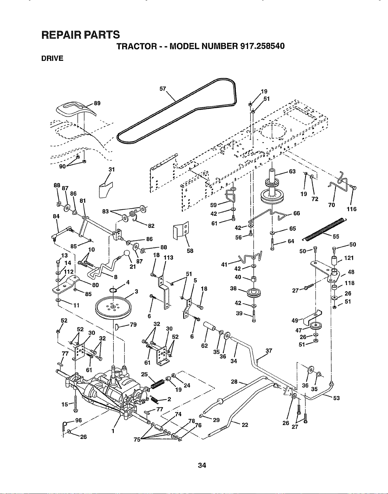
" " MODEL NUMBER 917'.268540
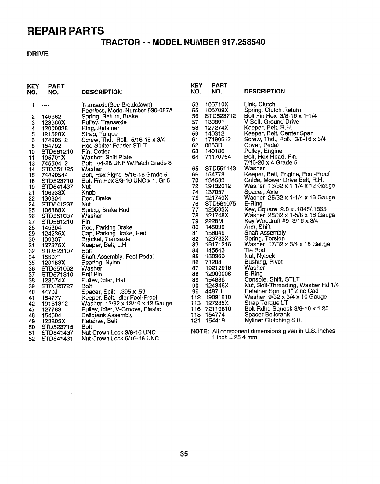
REPAIR PARTS
TRACTOR - - MODEL NUMBER 917.258540
DRIVE
KEY PART KEY PART
NO. NO. DESCRIPTION NO. NOo DESCRIPTION
1 .... Transaxle(See Breakdown) 53 105710X
Peerless, Model Number 930-057A 55 105709X
2 146682 Spring, Return, Brake 56 STD523712
3 123666X Pulley, Transaxle 57 13080t
4 12000028 Ring, Retainer 58 127274X
5 121520X Strap, Torque 59 140312
6 17490512 Screw, Th&, Rotlo 5/16-18 x 3/4 61 174906'12
8 154792 Rod Shifter Fender STLT 62 8883R
10 STD561210 Pin, Cotter 63 140186
11 105701X Washer, Shift Plate 64 71170764
13 74550412 Bolt 1/4-28 UNF W/Patch Grade 8
14 STD551125 Washer 65 STD551143
15 74490544 Bolt, Hex Flghd 5/16-18 Grade 5 66 154778
18 STD523710 Bolt Fin Hex 3/8-16 UNC x 1. Gr 5 70 134683
19 STD541437 Nut 72 19132012
21 106933X Knob 74 137057
22 130804 Rod, Brake 75 121749X
24 STD541237 Nut 76 STD581075
25 106888X Spring, Brake Rod 77 123583X
26 STD551037 Washer 78 121748X
27 STD561210 Pin 79 2228M
28 145204 Rod, Parking Brake 80 145090
29 124236X Cap, Parking Brake, Red 81 156049
30 130807 Bracket, Transaxle 82 123782X
31 127275X Keeper, Belt, L_H 83 19'171216
32 STD523107 Bolt 84 145643
34 155071 Shaft Assembly, Foot Pedal 85 150360
35 t20183X Bearing, Nylon 86 7t208
36 STD551062 Washer 87 19212016
37 STD571810 Roll Pin 88 12000008
38 123674X Pulley, Idler, Fiat 89 154886
39 STD523727 Bolt 90 124346X
40 4470J Spacer, Split °395 x .59 96 4497H
41 154777 Keeper, Belt, IdlerFooI-Proof 112 19091210
42 19131312 Washer 13/32 x 13/16 x 12 Gauge 113 127285X
47 127783 Pulley, Idler, V-Groove, Plastic 116 72110610
48 154604 Bellcrank Assembly 118 154774
49 123205X Retainer, Belt 121 154419
50 STD523715 Bolt
51 STD541437 Nut Crown Lock 3/8-16 UNC
52 STD541431 Nut Crown Lock 5/16-18 UNC
Link, Clutch
Spring, Clutch Return
Bolt Fin Hex 3/8-16 x 1-1/4
V-Belt, Ground Drive
Keeper, Belt, R.H.
Keeper, Bett, Center Span
Screw, Thd, Roll. 3/8-16 x 3/4
Cover, Pedal
Pulley, Engine
Bolt, Hex Head, Fin.
7/16-20 x 4 Grade 5
Washer
Keeper, Belt, Engine, Fool-Proof
Guide, Mower Drive Belt, R.H.
Washer 13/32 x 14/4 x 12 Gauge
Spacer, Axle
Washer 25/32 x 1_1/4 x 16 Gauge
E-Ring
Key, Square 2.0 x .1845/o1865
Washer 25/32 x 1-5/8 x 16 Gauge
Key Woodruff #9 3/16 x 3/4
Arm, Shift
Shaft Assembly
Spring, Torsion
Washer 17/32 x 3/4 x 16 Gauge
Tie Rod
Nut, Nylock
Bushing, Pivot
Washer
E-Ring
Console, Shift, STLT
Nut, Self-Threading, Washer Hd 1/4
Retainer Spring 1" Zinc Cad
Washer 9/32 x 3/4 x 10 Gauge
Strap Torque LT
Bolt Rdhd Sqneck 3/8-16 x 1.25
Spacer Bellcrank
Nyliner Clutching STL
NOTE: AUcomponent dimensions given in U°& inches
1 inch = 254 mm
35
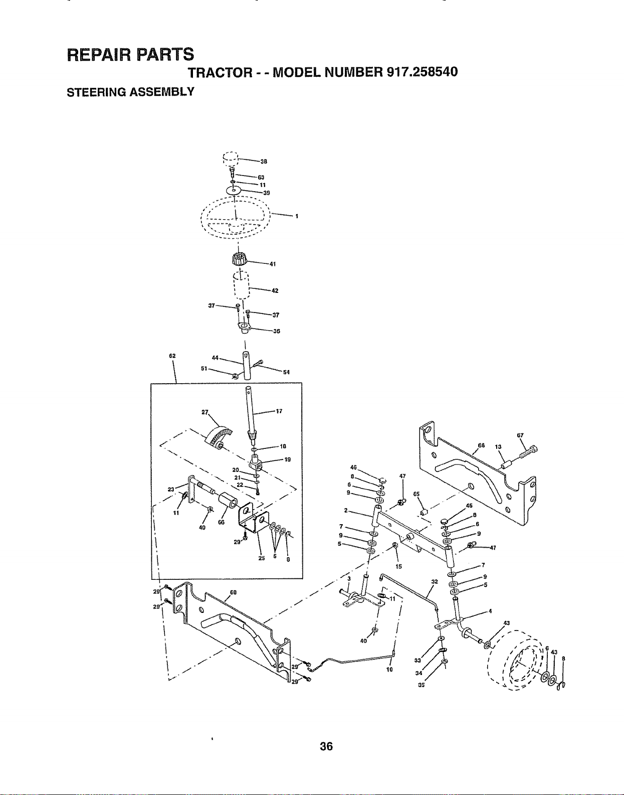
REPAIR PARTS
TRACTOR - - MODEL NUMBER 917.258540
STEERING ASSEMBLY
L '
62
It" , i
47
7
15
36
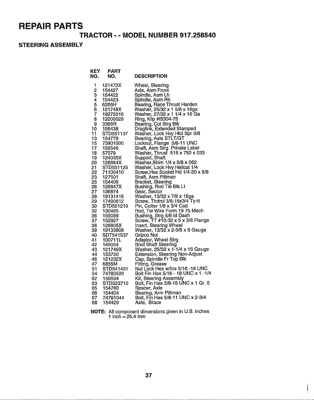
REPAIR PARTS
TRACTOR - - MODEL NUMBER 917.258540
STEERING ASSEMBLY
KEY PART
NO. NO. DESCRIPTION
1 12t472X
2 154427
3 154422
4 154423
5 6266H
6 121748X
7 19272016
8 12000029
9 3366R
10 156438
1! STD551137
13 154779
15 739010O0
17 156546
18 57079
19 124035X
20 126684X
21 STD551125
22 71100410
23 127501
25 154406
26 126847X
27 '136874
28 19131416
29 17490612
30 STD56i210
32 130465
36 155099
37 152927
38 126805X
39 19133808
40 SDT541537
4t 10071iL
42 145054
43 121749X
44 153720
46 121232X
47 6855M
51 STD541431
54 74780520
62 156594
63 STD523710
65 154780
66 1544O4
67 74781044
68 154429
NOTE:
Wheel, Steering
Axle, Asm Front
Spindle, Asm Lh
Spindle, Asm Rh
Bearing, Race Thrust Harden
Washer, 25/32 x 1 5/8 x 16ga
Washer, 27/32 x 1 1/4 x 16 Ga
Ring, Klip #t5304-75
Bearing, Col Strg BIk
Dr'aglink, Extended Stamped
Washer, Lock Hvy Hlcl Spr 3/8
Bearing, Axle STLT/GT
Locknut, Flange 5/8-11 UNC
Shaft, Asm Strg Private Label
Washer, Thrust 515 x 750 x 033
Support, Shaft
Washer, Shim 1/4 x 5/8 x 062
Washer, Lock Hvy Helical 1/4
Screw,Hex Socket Hd 1/4-20 x 5/8
Shaft, Asm Pittman
Bracket, Steering
Bushing, Rod Tie BIk Lt
Gear, Sector
Washer, 13/32 x 7/8 x 16ga
Screw, Thdrol 3/8-16x3/4 Ty-tt
Pin, Cotter 1/8 x 3/4 Cad
Rod, Tie Wire Form 19 75 Mech
Bushing, Strg 5/8 Id Dash
Screw, TT #10-32 x 5 x 3/8 Flange
Insert, Steering Wheel
Washer, 13/32 x 2-3/8 x 8 Gauge
Gripco Nut
Adaptor, Wheel Strg
Boot Shaft Steering
Washer, 25/32 x 1-1/4 x 16 Gauge
Extension, Steering Non-Adjust
Cap, Spindle Fr Top BIk
Fitting, Grease
Nut Lock Hex w/Ins 5/16 -18 UNC
Bolt Fin Hex 5/16 - 18 UNC x 1 -1/4
Kit, Steering Assembly
Bolt, Fin Hex 3/8-16 UNC x 1 Gr. 5
Spacer, Axle
Bearing, Arm Pittman
Bolt, Fin Hex 5/8-11 UNC x 2-3/4
Axle, Brace
All component dimensions given in U.S.. inches
! inch = 25.4 mm
37

REPAIR PARTS
TRACTOR - - MODEL NUMBER 917.258540
SEAT ASSEMBLY
23
12
5
21
KEY
NO,
1
2
3
4
5
6
7
8
9
10
12
13
14
PART
NO.
140123
140551
STD523710
19131610
145006
STD541437
124181X
17490616
19131614
155925
121246X
12t248X
7205O411
DESCRIPTION
Seat
Bracket, Pivot, Seat
Bolt
Washer 13/32 x I x 10 Gauge
Clip, Push-In Hinged
Nut
Spring, Seat
Screw, Thd., Roll. 3/8-16 x 1
Washer 13/32 x t x 14 Gauge
Pan, Seat Emboss QCK Conh.
Bracket, Switch Mounting
Bushing, Snap
Bolt, Carriage 1/4-20 x 1-3/8
KEY PART
NO, NO. DESCRIPTION
15 134300 Spacer, Sprit 28 x _88
t6 121250X Spring
17 123976X Locknut, Flange 1/4 Grade 5
2t 153236 Bolt, Shoulder 5/16-18 UNC
22 STD541431 Nut
23 74780814 Bolt, Hex Head, Fin.
1/2-13 x 7/8 Grade 5
24 19171912 Washer 17/32 x 1-3/16 x 12 Gauge
25 127018X Bolt, Shoulder- 5/16-18 x.62
26 STD551150 Washer, Lock
NOTE: All component dimensions given in U oS.inches
1 inch = 25.4 rnm
38
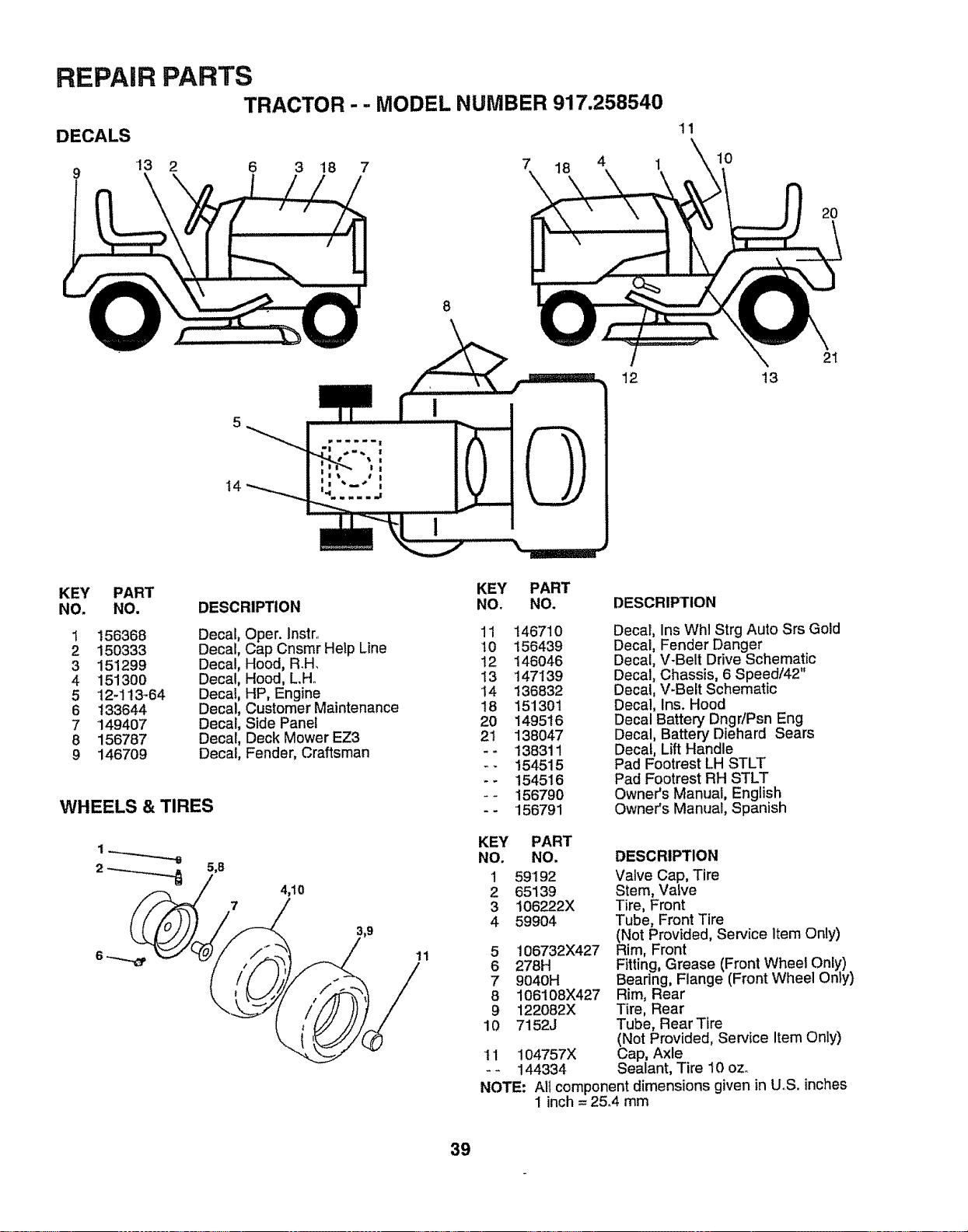
REPAIR PARTS
TRACTOR - - MODEL NUMBER 917.258540
DECALS
9 13 2 6 3 18 7 7 18 4 1
'11
10
2O
8
t4
12 13
21
KEY
NO.
1
2
3
4
5
6
7
8
9
PART
NO.
156368
150333
151299
151300
12-113-64
133644
149407
156787
146709
DESCRIPTION
Decal, Oper. Instr..
Decal, Cap Cnsmr Help Line
Decal, Hood, R.H_
Decal, Hood, L.Ho
Decal, HP, Engine
Decal, Customer Maintenance
Decal, Side Panel
Decal, Deck Mower EZ3
Decal, Fender, Craftsman
WHEELS & TIRES
4,10
11
KEY PART
NO, NO, DESCRIPTION
11
t0
12
13
14
18
20
2t
14671O
156439
146046
147139
136832
15'1301
149516
138047
138311
154515
154516
156790
156791
Decal, Ins Whl Strg Auto Srs Gold
Decal, Fender Danger
Decal, V-Belt Drive Schematic
Decal, Chassis, 6 Speed/42"
Decal, V-Belt Schematic
Decal, Ins. Hood
Decal Battery DngriPsn Eng
Decal, Battery Diehard Sears
Decal, Lift Handle
Pad Footrest LH STLT
Pad Footrest RH STLT
Owner's Manual, English
Owner's Manual, Spanish
KEY PART
NO. NO,
1 59192
2 65139
3 106222X
4 59904
5 106732X427
6 278H
7 9040H
8 106108X427
9 122082X
10 7152J
11 104757X
-- 144334
DESCRIPTION
Valve Cap, Tire
Stem, Valve
Tire, Front
Tube, Front Tire
(Not Provided, Service Item Only)
Rim, Front
Fitting, Grease (Front Wheel Only)
Beadng, Flange (Front Wheel Only)
Rim, Rear
Tire, Rear
Tube, Rear Tire
(Not Provided, Service Item Only)
Cap, Axle
Sealant, Tire 10 oz_
NOTE: Alt component dimensions given in UoS. inches
1 inch = 25.4 mm
39
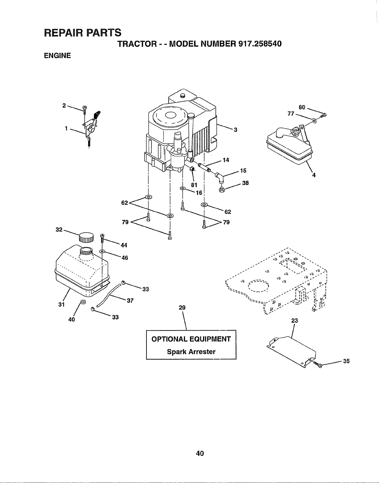
REPAIR
ENGINE
PARTS
TRACTOR-- MODEL NUMBER 917,258540
38
33
33
29
\
.+" _ ,.€_:_._ ".
23
OPTIONAL EQUIPMENT
Spark Arrester
4O
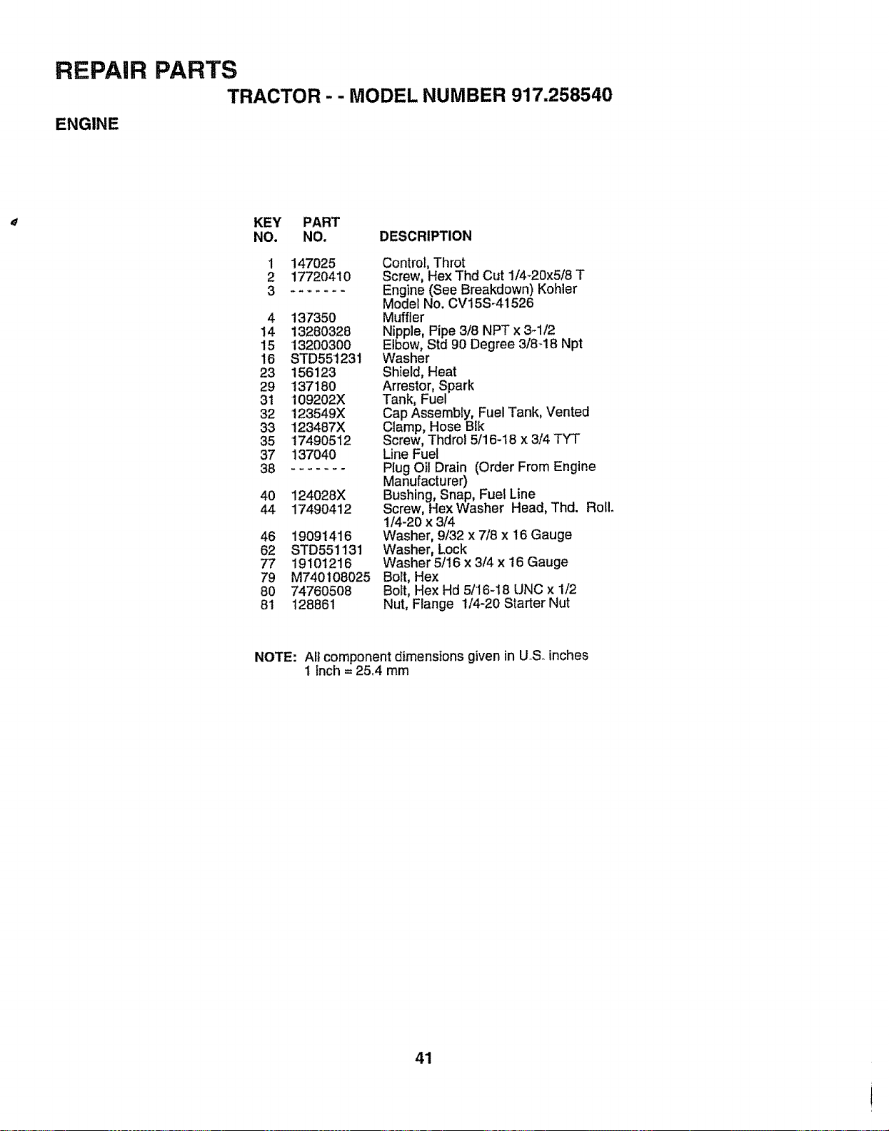
REPAIR
ENGINE
PARTS
TRACTOR -- MODEL NUMBER 917.258540
KEY PART
NO. NO. DESCRIPTION
1
2
3
147025
17720410
4 137350
14 13280328
15 132003OO
16 STD551231
23 156123
29 137180
31 109202X
32 123549X
33 123487X
35 17490512
37 137O40
38 .......
40 124028X
44 17490412
46 19O91416
62 STD551131
77 191O1216
79 M740108025
8O 747605O8
81 128861
Control, Throt
Screw, Hex Thd Cut 1/4-20x5/8 T
Engine (See Breakdown) Kohler
Model No. CV15S_41526
Muffler
Nipple, Pipe 3/8 NPT x 3-1t2
Elbow, Std 90 Degree 318-18 Npt
Washer
Shield, Heat
Arrestor, Spark
Tank, Fuel
Cap Assembly, Fuel Tank, Vented
Ciamp, Hose Blk
Screw, Thdrol 5/16-18 x 3/4 TYT
Line Fuel
Plug Oil Drain (Order From Engine
Manufacturer)
Bushing, Snap, Fuel Line
Screw, Hex Washer Head, Thd. Roll.
1/4-20 x 3/4
Washer, 9/32 x 7/8 x 16 Gauge
Washer, Lock
Washer 5/16 x 3/4 x 16 Gauge
Bolt, Hex
Bolt, Hex Hd 5/16-18 UNC x 1/2
Nut, Flange 1/4-20 Starter Nut
NOTE: All component dimensions given in U,.S_inches
1 inch = 25..4 mm
41
!
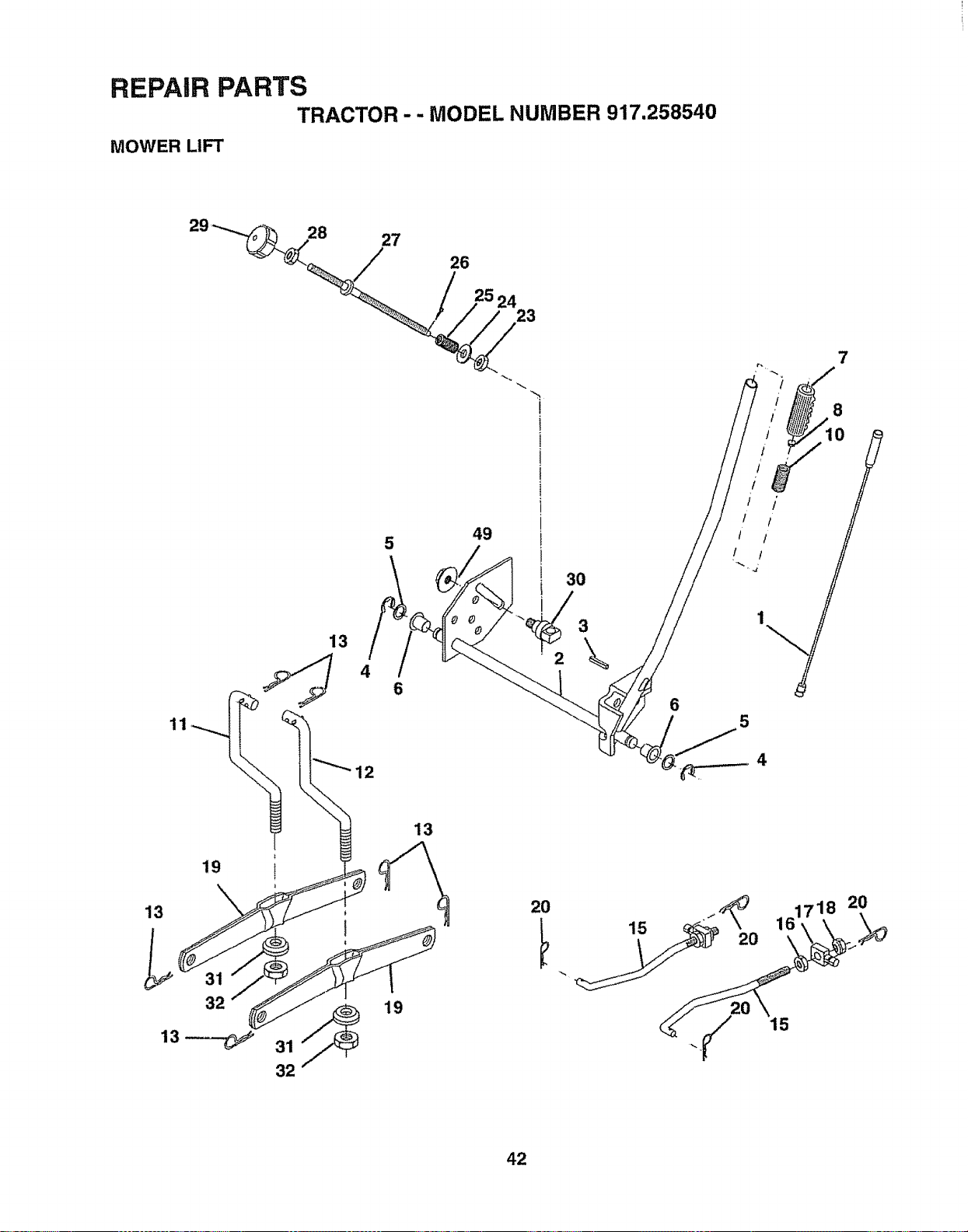
REPAIR PARTS
TRACTOR - - MODEL NUMBER 917,258540
MOWER LIFT
28
27
26
24
23
5
49
6
7
6
8
/ 10 ;
i /'
/ 1
/ /
5
i
i
32
13
19
2O
15
2O
718 20
42
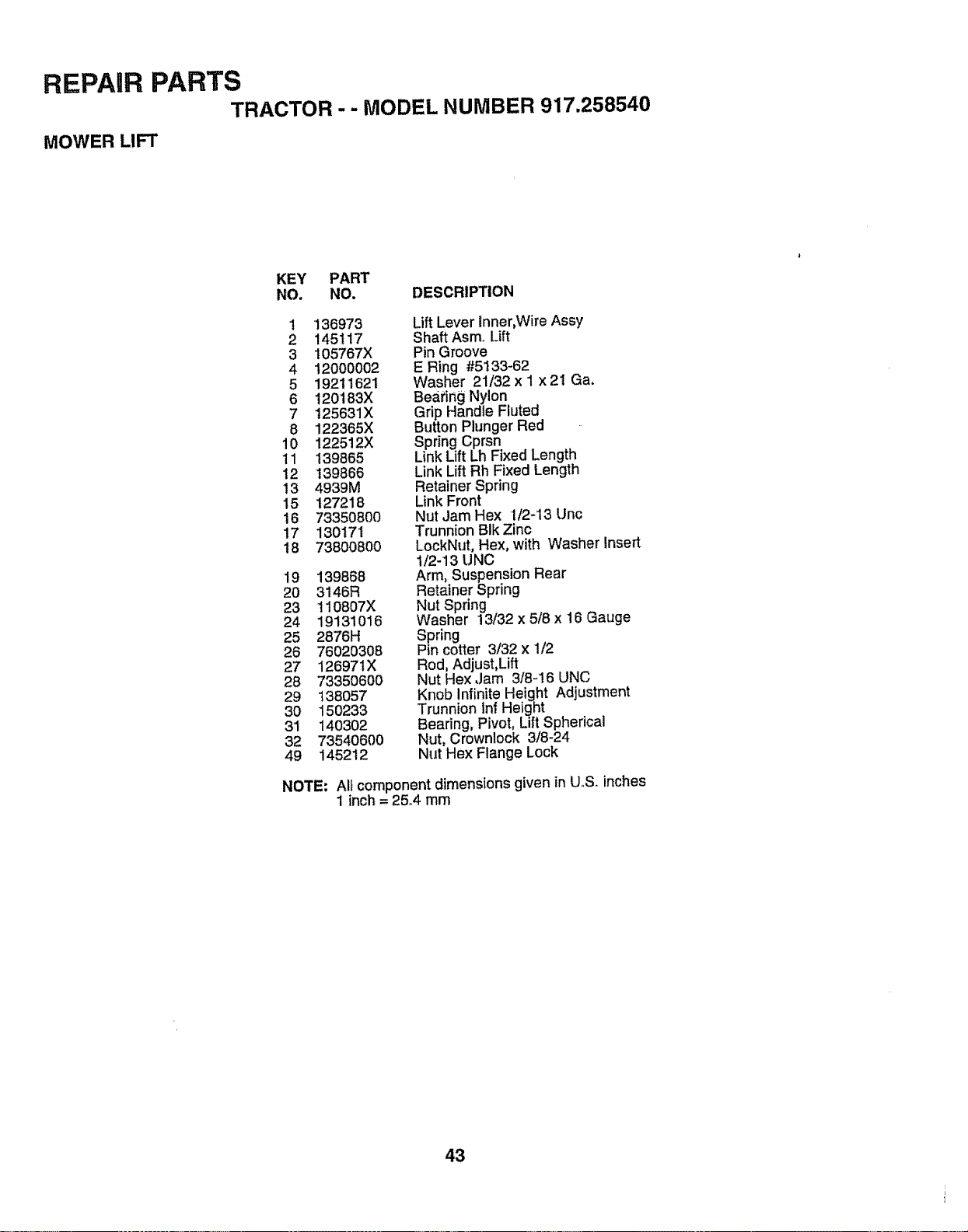
REPAIR PARTS
TRACTOR - - MODEL NUMBER 917.258540
MOWER LIFT
KEY PART
NO. NO. DESCRIPTION
1 136973
2 145117
3 105767X
4 12000002
5 19211621
6 t20183X
7 125631X
8 122365X
10 122512X
11 I39865
12 139866
13 4939M
15 127218
16 73350800
17 130171
18 73800800
19 139868
2O 3146R
23 t10807X
24 19131016
25 2676H
26 76020308
27 126971X
28 73350600
29 138057
30 150233
31 140302
32 73540600
49 145212
Lift Lever inner,Wire Assy
Shaft Asmo Lift
Pin Groove
E Ring #5133-62
Washer 21/32 x I x 2I Ga.
Beating Nylon
Grip Handle Fluted
Button Plunger Red
Spring Cprsn
Link Lift Lh Fixed Length
Link Lift Rh Fixed Length
Retainer Spring
Link Front
Nut Jam Hex 1/2-13 Unc
Trunnion BIk Zinc
LockNut, Hex, with Washer Insert
1/2-13 UNC
Arm, Suspension Rear
Retainer Spring
Nut Spring
Washer 13/32 x 5/8 x 16 Gauge
Spring
Pin cotter 3/32 x 1/2
Rod, Adjust,Lift
Nut Hex ,Jam 3/8-16 UNC
Knob Infinite Height Adjustment
Trunnion inf Height
Bearing, Pivot, Lift Spherical
Nut, Crownlock 3/8-24
Nut Hex Flange Lock
NOTE: All component dimensions given in U,S. inches
1 inch = 25°4 rnm
43
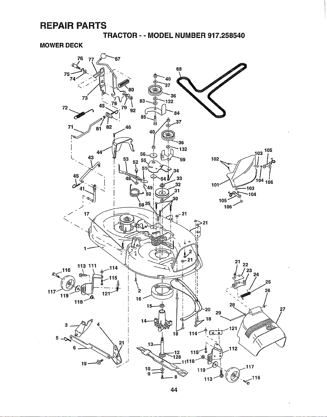
REPAIR PARTS
MOWER DECK TRACTOR . . MODEL NUMBER 917.258540
76
73
71
82
92
33
32
102
105
44
29
18
21 22
24
25
28
115"_
7
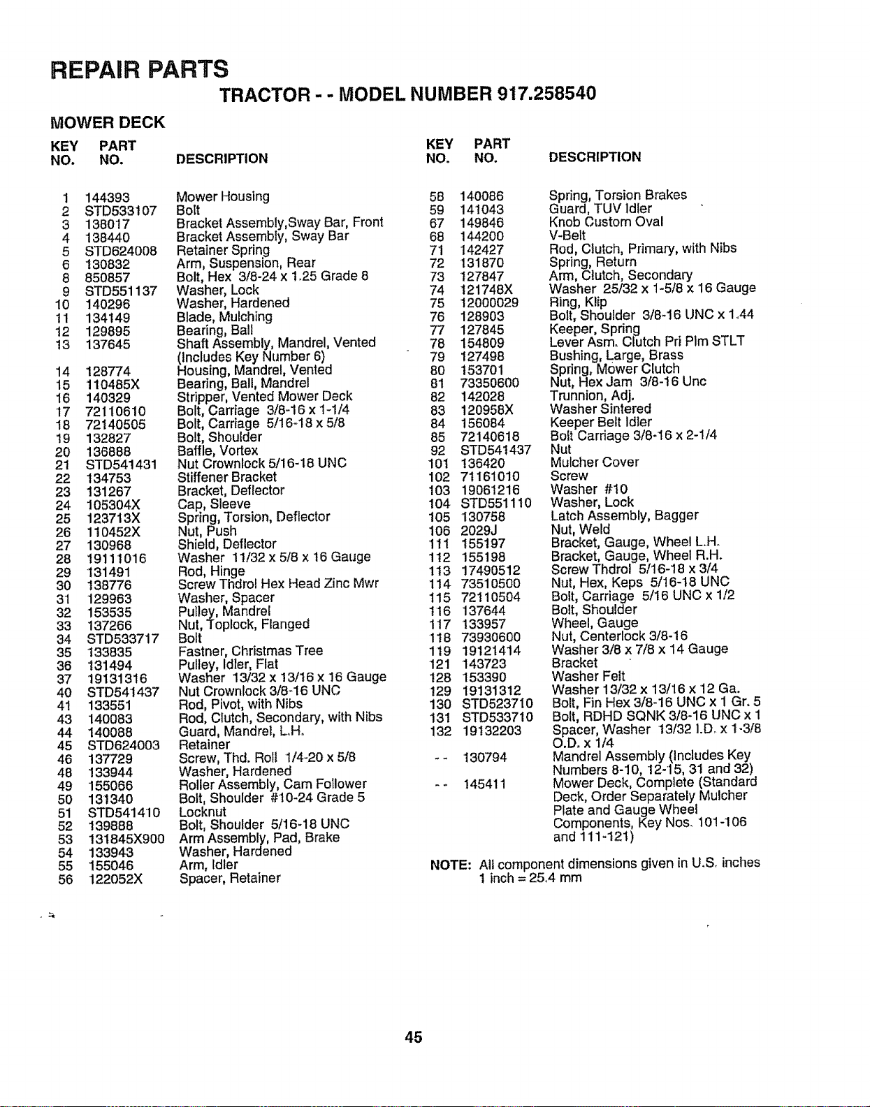
REPAIR PARTS
TRACTOR- - MODEL NUMBER 917.258540
MOWER DECK
KEY PART KEY PART
NO. NO. DESCRIPTION NO. NO. DESCRIPTION
1 144393
2 STD533107
3 138017
4 138440
5 STD624008
6 130832
8 850857
9 STD551137
I0 140296
11 134149
t2 129895
t3 137645
14 128774
15 110485X
16 140329
17 72110610
18 72140505
19 132827
20 136888
21 STD541431
22 134753
23 131267
24 105304X
25 123713X
26 110452X
27 130968
28 19111016
29 _31491
30 138776
31 129963
32 153535
33 137266
34 STD533717
35 133835
36 131494
37 19181316
40 STD541437
41 133551
43 14O083
44 14OO88
45 STD624003
46 137729
48 133944
49 155066
50 131340
51 STD541410
52 139888
53 t31845X900
54 133943
55 155046
56 122052X
Mower Housing 58 140086
Bolt 59 141043
Bracket Assembly, Sway Bar, Front 67 149846
Bracket Assembly, Sway Bar 68 144200
Retainer Spring 71 142427
Arm, Suspension, Rear 72 131870
Bolt, Hex 3/8-24 x 1,25 Grade 8 73 127847
Washer, Lock 74 t21748X
Washer, Hardened 75 12000029
Blade, Mulching 76 128903
Bearing, Ball 77 127845
Shaft Assembly, Mandrel, Vented 78 154809
(Includes Key Number 6) 79 127498
Housing, Mandrel, Vented 80 153701
Bearing, Ball, Mandrel 81 73350600
Stripper, Vented Mower Deck 82 142028
Bolt, Carriage 3/8-16 x 1-1/4 83 120958X
Bolt, Carriage 5/16-18 x 5/8 84 156084
Bolt, Shoulder 85 72140618
Baffle, Vortex 92 STD541437
Nut Crownlock 5/16-18 UNC 101 136420
Stiffener Bracket 102 7! 161010
Bracket, Deflector 103 19061216
Cap, Sleeve !04 STD551110
Spring, Torsion, Deflector 105 130758
Nut, Push 106 2029J
Shield, Deflector 111 155197
Washer 11/32 x 5/8 x 16 Gauge 112 155198
Rod, Hinge 113 17490512
Screw Thdrol Hex Head Zinc Mwr 114 73510500
Washer, Spacer 115 72110504
Pulley, Mandrel I16 137644
Nut, Toplock, Flanged 117 133957
Bolt 1t8 73930600
Fastner, Christmas Tree 1t 9 19121414
Pulley, Idler, Flat 121 143723
Washer 13/32 x 13/16 x 16 Gauge 128 153390
Nut Crownlock 3/8-16 UNC t29 19131312
Rod, Pivot, with Nibs 130 STD523710
Rod, Clutch, Secondary, wlth Nibs 131 STD533710
Guard, Mandrel, LH. 132 19132203
Retainer
Screw, Thd. Roll I/4-20 x 5/8 - - 130794
Washer, Hardened
Roller Assembly, Cam Follower - - 145411
Bolt, Shoulder #10-24 Grade 5
Locknut
Bolt, Shoulder 5/16-18 UNC
Arm Assembly, Pad, Brake
Washer, Hardened
Arm, Idler
Spacer, Retainer
Spring, Torsion Brakes
Guard, TUV Idler
Knob Custom Oval
V-Belt
Rod, Clutch, Primary, with Nibs
Spring, Return
Arm, Clutch, Secondary
Washer 25/32 x 1-5/8 x 16 Gauge
Ring, Klip
Bolt, Shoulder 3/8-16 UNC x 1.44
Keeper, Spring
Lever Asm. Clutch Prt Plm STLT
Bushing, Large, Brass
Spring, Mower Clutch
Nut, Hex Jam 3/8-16 Unc
Trunnion, Adj.
Washer Sintered
Keeper Belt Idler
Bolt Carriage 3/8-16 x 2-1/4
Nut
Mulcher Cover
Screw
Washer #10
Washer, Lock
Latch Assembly, Bagger
Nut, Wetd
Bracket, Gauge, Wheel L..Ho
Bracket, Gauge, Wheel R.H.
Screw Thdrot 5/16-18 x 3/4
Nut, Hex, Keps 5/!6-18 UNC
Bolt, Carriage 5/16 UNC x 1/2
Bolt, Shoulder
Wheel, Gauge
Nut, Centerlock 3/8-'16
Washer 3/8 x 7/8 x 14 Gauge
Bracket
Washer Felt
Washer 13/32 x 13/16 x '12 Ga.
Bolt, Fin Hex 318..16UNC x 1 Gr. 5
Bolt, RDHD SQNK 3/8-16 UNC x 1
Spacer, Washer 13/32 I.D. x 1-3/8
O.D. x 1/4
MandreJ Assembly (lncJudes Key
Numbers 8-10, 12-'15, 31 and 32)
Mower Deck, Complete (Standard
Deck, Order Separately Mulcher
Plate and Gauge Wheel
Components, Key Nos° 10!-106
and 111-12I)
NOTE: All component dimensions given in U.S. inches
1 inch = 25°4 mm
45
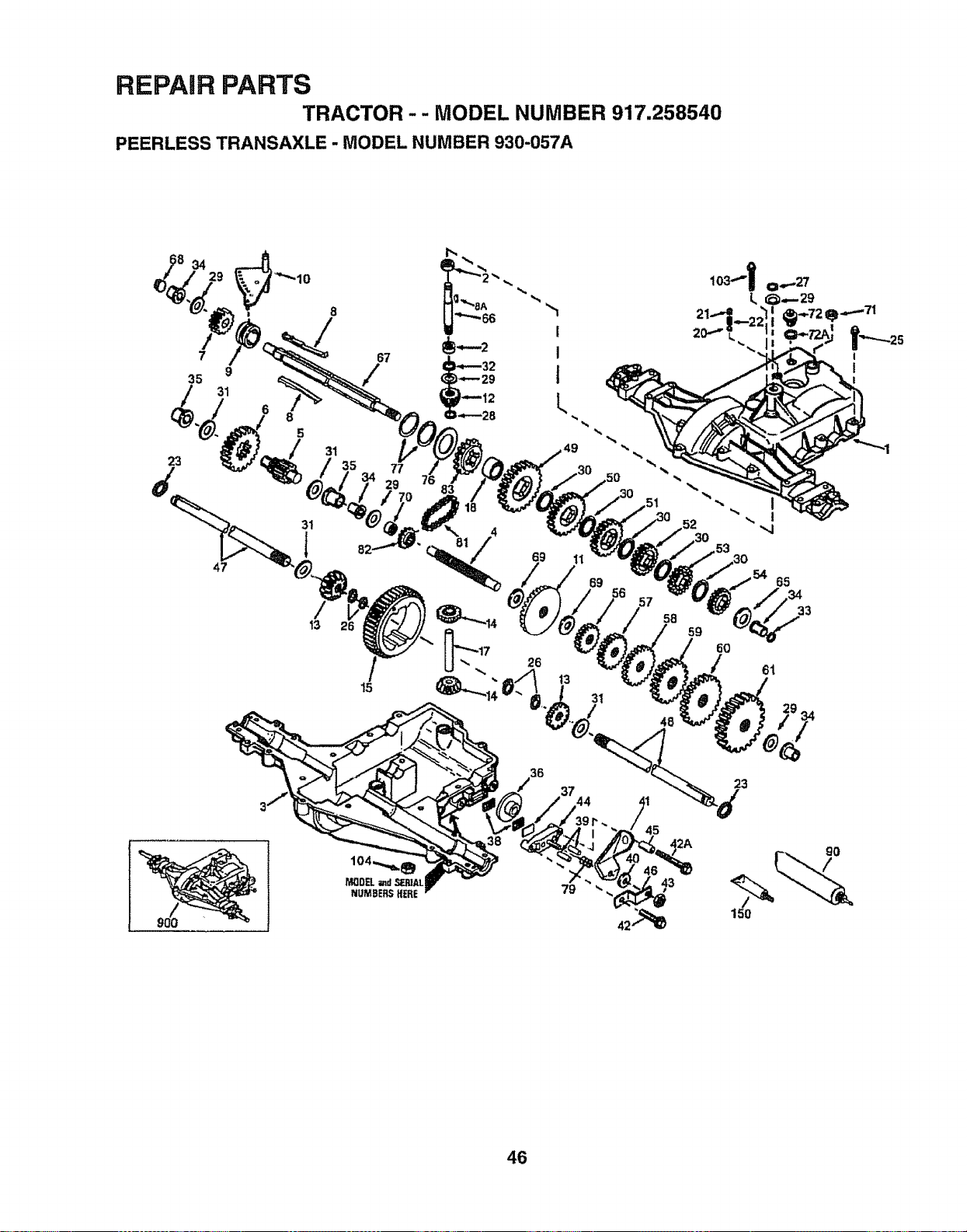
REPAIR PARTS
TRACTOR -- MODEL NUMBER 917.258540
PEERLESS TRANSAXLE - MODEL NUMBER 930-057A
34
7 67
35 9 /
31
6
8
5
23
47
31
/
't3
35
77
29
15
_._/4 ,52 --
69 11 ,53
7 58 33
23
45
36
79
43
46
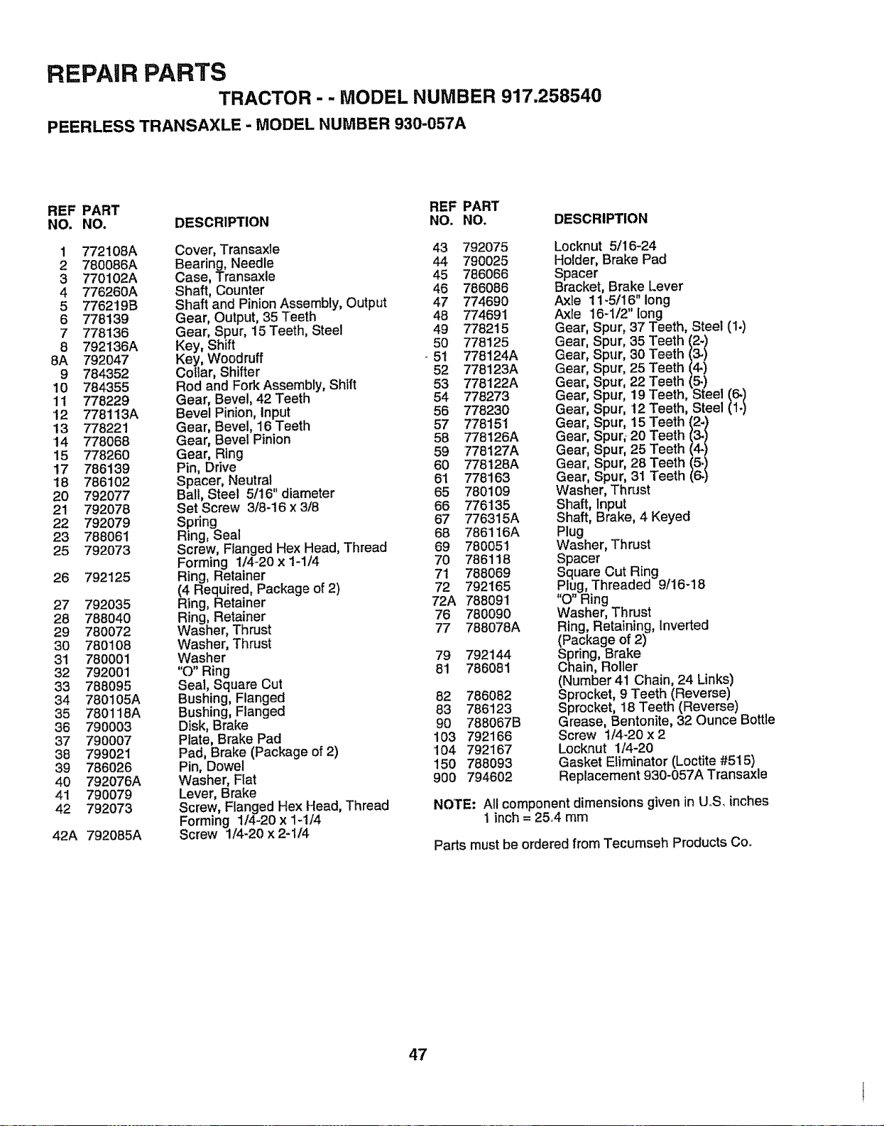
REPAIR PARTS
TRACTOR- - MODEL NUMBER 917,258540
PEERLESS TRANSAXLE - MODEL NUMBER 930-057A
REF PART REF PART
NO. NO. DESCRIPTION NO. NO. DESCRIPTION
1 772108A Cover, Transaxle
2 780086A Bearing, Needle
3 770102A Case, Transaxle
4 776260A Shaft, Counter
5 776219B Shaft and Pinion Assembly, Output
8 778139 Gear, Output, 35 Teeth
7 778136 Gear, Spur, 15 Teeth, Steel
8 792136A Key, Shift
8A 792047 Key, Woodruff
9 784352 Collar, Shifter
10 784355 Rod and Fork Assembly, Shift
11 778229 Gear, Bevel, 42 Teeth
'I2 778113A Bevel Pinion, Input
13 778221 Gear, Bevel, 16 Teeth
14 778068 Gear, Bevel Pinion
15 778260 Gear, Ring
17 786139 Pin, Drive
18 786t02 Spacer, Neutral
20 792077 Ball, Steel 5/!6" diameter
21 792078 Set Screw 3/8-16 x 3/8
22 792079 Spring
23 788061 Ring, Seal
25 792073 Screw, Flanged Hex Head, Thread
Forming 114_20x 1-1/4
26 792125 Ring, Retainer
(4 Required, Package of 2)
27 792035 Ring, Retainer
28 788040 Ring, Retainer
29 780072 Washer, Thrust
30 780108 Washer, Thn_st
31 780001 Washer
32 792001 "0" Ring
33 788095 Seal, Square Cut
34 780105A Bushing, Flanged
35 780118A Bushing, Flanged
36 790003 Disk, Brake
37 790007 Plate, Brake Pad
38 799021 Pad, Brake (Package of 2)
39 786026 Pin, Dowel
40 792076A Washer, Flat
41 790079 Lever, Brake
42 792073 Screw, Flanged Hex Head, Thread
Forming 1/4-20 x 1-1/4
42A 792085A Screw 1/4-20 x 2-1/4
43
44
45
46
47
48
49
50
51
52
53
54
56
57
58
59
60
61
65
66
67
68
69
7O
71
72
72A
76
77
792075
790025
786066
786086
774690
774691
778215
778125
778124A
778123A
778122A
778273
778230
77815'1
778126A
778127A
778128A
778163
7801O9
776135
776315A
786116A
780051
786118
788069
792165
788091
780090
788078A
79 792144
81 786O81
82 786O82
83 786123
90 788067B
103 792166
'104 792167
150 788093
900 794602
Gear, Spur, 35 Teeth (2-)
Gear, Spur, 30 Teeth (3.)
Gear, Spur, 25 Teeth (4-)
Gear, Spur, 22 Teeth (5.)
Gear, Spur, 19 Teeth, Stee'/_./
Gear, Spur, '12 Teeth, Steel
Gear, Spur, 15 Teeth (2-)
Gear, Spur; 20 Teeth
Gear, Spur, 25 Teeth
Gear, Spur, 28 Teeth/_ /
Gear, Spur, 31 Teeth
Washer, ThnJst
Shaft, Input
Shaft, Brake, 4 Keyed
Plug
Washer, Thrust
Spacer
Square Cut Ring
Plug, Threaded 9/16-18
' O" Ring
Washer, Thrust
Ring, Retaining, Inverted
(Package of 2)
Spring, Brake
Chain, Roller
(Number 41 Chain, 24 Links)
Sprocket, 9 Teeth (Reverse)
Sprocket, t8 Teeth (Reverse)
Grease, Bentonite, 32 Ounce Bottle
Screw 1/4-20 x 2
Locknut 1/4-20
Gasket Eliminator (Loctite #515)
Replacement 930-057A Transaxle
NOTE: All component dimensions given in UoS, inches
1 inch = 25,4 mm
Parts must be ordered from Tecumseh Products Co.
47

REPAIR PARTS
TRACTOR - - MODEL NUMBER 917.258540
KOHLER ENGINE - MODEL NUMBER CV15S, TYPE NUMBER PS-41526
11/
BLOWER HOUSING AND BAFFLES
ENQ,.E€O.TROLSI .......:::::::: _ ........:::
14....,_ /:,/3
"'16 13 _: 8 6 5
_1 _4
6
iiiiiiii , ii ¸
AIR INTAKE
EXHAUSTI
48
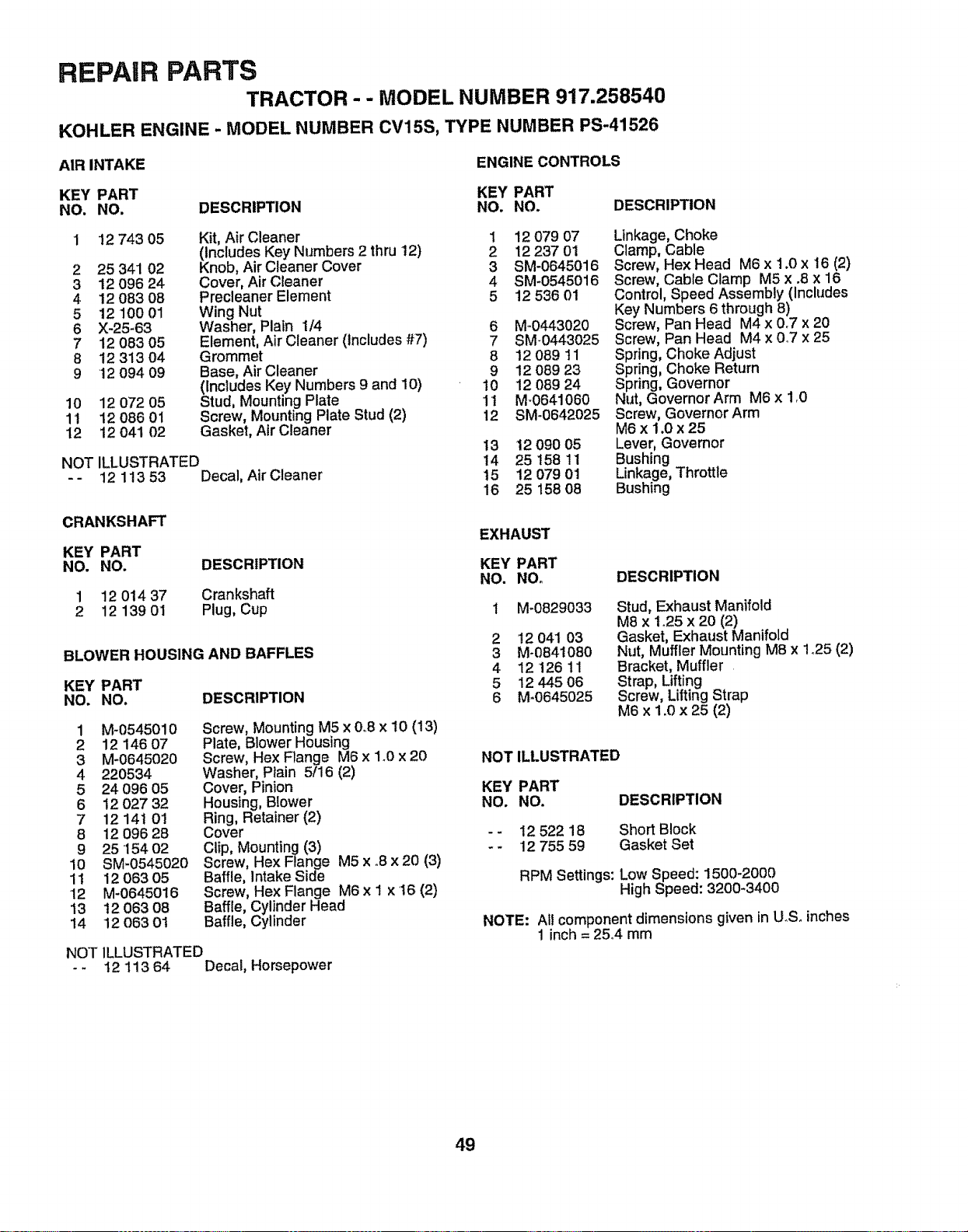
REPAIR PARTS
TRACTOR - - MODEL NUMBER 917.258540
KOHLER ENGINE- MODEL NUMBER CV15S, TYPE NUMBER PS-41526
AIR INTAKE
ENGINE CONTROLS
KEY PART KEY PART
NO. NO. DESCRIPTION NO. NO.
DESCRIPTION
12 743 05
2 25 341 02
3 12 096 24
4 12083 08
5 12 100 01
6 X-25-63
7 12 083 05
8 12 313 04
9 12 094 09
10 12 072 05
1t 12 O86 0t
12 12 041 02
NOT
Kit, Air Cleaner 1
(Includes Key Numbers 2 thru 12) 2
Knob, Air Cleaner Cover 3
Cover, Air Cleaner 4
Precleaner Element 5
Wing Nut
Washer, Plain 1/4 6
Element, Air Cleaner (Includes #7) 7
Grommet 8
Base, Air Cleaner 9
(Includes Key Numbers 9 and 10) 10
Stud, Mounting Plate 11
Screw, Mounting Plate Stud (2) 12
Gasket, Air Cleaner
ILLUSTRATED
12 113 53 Decal, Air Cleaner
CRANKSHAFT
KEY PART
NO. NO.
1 12 014 37
2 12 139 01
DESCRIPTION
Crankshaft
Plug, Cup
BLOWER HOUSING AND BAFFLES
KEY PART
NO. NO. DESCRIPTION
1 M-0545010
2 12 14607
3 M-0645020
4 220534
5 24 096 05
6 12 027 32
7 12 14! 0!
8 12 09628
9 2515402
10 SM-0545020
11 12 063 05
•12 M-0645016
13 12 063 08
14 12 063 01
Screw, Mounting M5 x 0.8 x 10 (13)
Plate, Blower Housing
Screw, Hex Flange M6 x 1_0x 20
Washer, Plain 5/16 (2)
Cover, Pinion
Housing, Blower
Ring, Retainer (2)
Cover
Clip, Mounting (3)
Screw, Hex Flange M5 x ,.8x 20 (3)
Baffle, Intake Side
Screw, Hex Flange M6 x I x t6 (2)
Baffle, Cylinder Head
Baffle, Cylinder
NOT ILLUSTRATED
- - t2 113 64 Decal, Horsepower
12 079 07
12 237 01
SM-0645016
SM-0545016
12 536 01
M.0443020
SM-0443025
12 089 11
12 089 23
12 089 24
M-0641060
SM-0642025
13 12 O9005
14 25 158 11
15 12 079 01
16 25 158 O8
Linkage, Choke
Clamp, Cable
Screw, Hex Head M6 x 1.0 x 16 (2)
Screw, Cable Clamp M5 x .8 x 16
Control, Speed Assembly (includes
Key Numbers 6 through 8)
Screw, Pan Head M4 x 0.7 x 20
Screw, Pan Head M4 x 0.7 x 25
Spring, Choke Adjust
Spring, Choke Return
Spring, Governor
Nut, Governor Arm M6 x 1_0
Screw, Governor Arm
M6 x 1.0 x 25
Lever, Governor
Bushing
Linkage, Throttle
Bushing
EXHAUST
KEY PART
NO. NOo
1 M_0829033
2 t2 041 03
3 M-0841080
4 12 12611
5 12445 06
6 M-0645025
DESCRIPTION
Stud, Exhaust Manifold
M8 x 1_25 x 20 (2)
Gasket, Exhaust Manifold
Nut, Muffler Mounting M8 x 1°25 (2)
Bracket, Muffler
Strap, Lifting
Screw, Lifting Strap
M6 x 1.0 x 25 (2)
NOT ILLUSTRATED
KEY PART
NO. NO. DESCRIPTION
- - 12 522 18 Short Block
- - '12755 59 Gasket Set
RPM Settings: Low Speed: 1500-2000
High Speed: 3200-3400
NOTE: At! component dimensions given in UoSoinches
1 inch = 25°4 mm
49

REPAIR PARTS
TRACTOR -- MODEL NUMBER 917.258540
KOHLER ENGINE- MODEL NUMBER CV15S, TYPE NUMBER PS-41526
FUEL SYSTEM i
32
31 /
30
20--
19
14 23
_ _29
CYLINDER HEAD, VALVE AND BREATHER_ I
I0
50
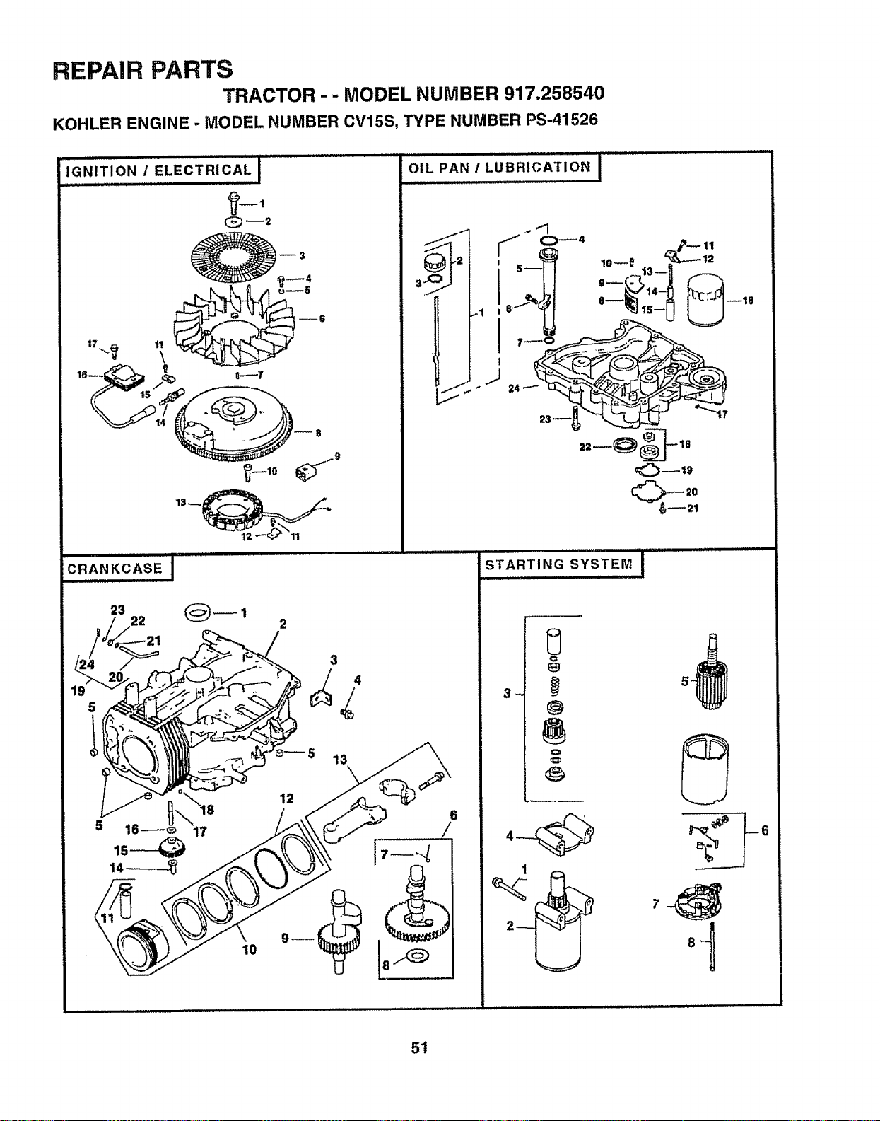
REPAIR PARTS
TRACTOR -- MODEL NUMBER 917.258540
KOHLER ENGINE - MODEL NUMBER CV15S, TYPE NUMBER PS-41526
.......................E,.'_CTRC'LI......
IGNITION / I
LJ/iJ
CRANKCASE
13 __
23
22
2
3
13
17
_,,o,LP;.,,.-0BR,c..,o.I............
J
J
_19
1
51
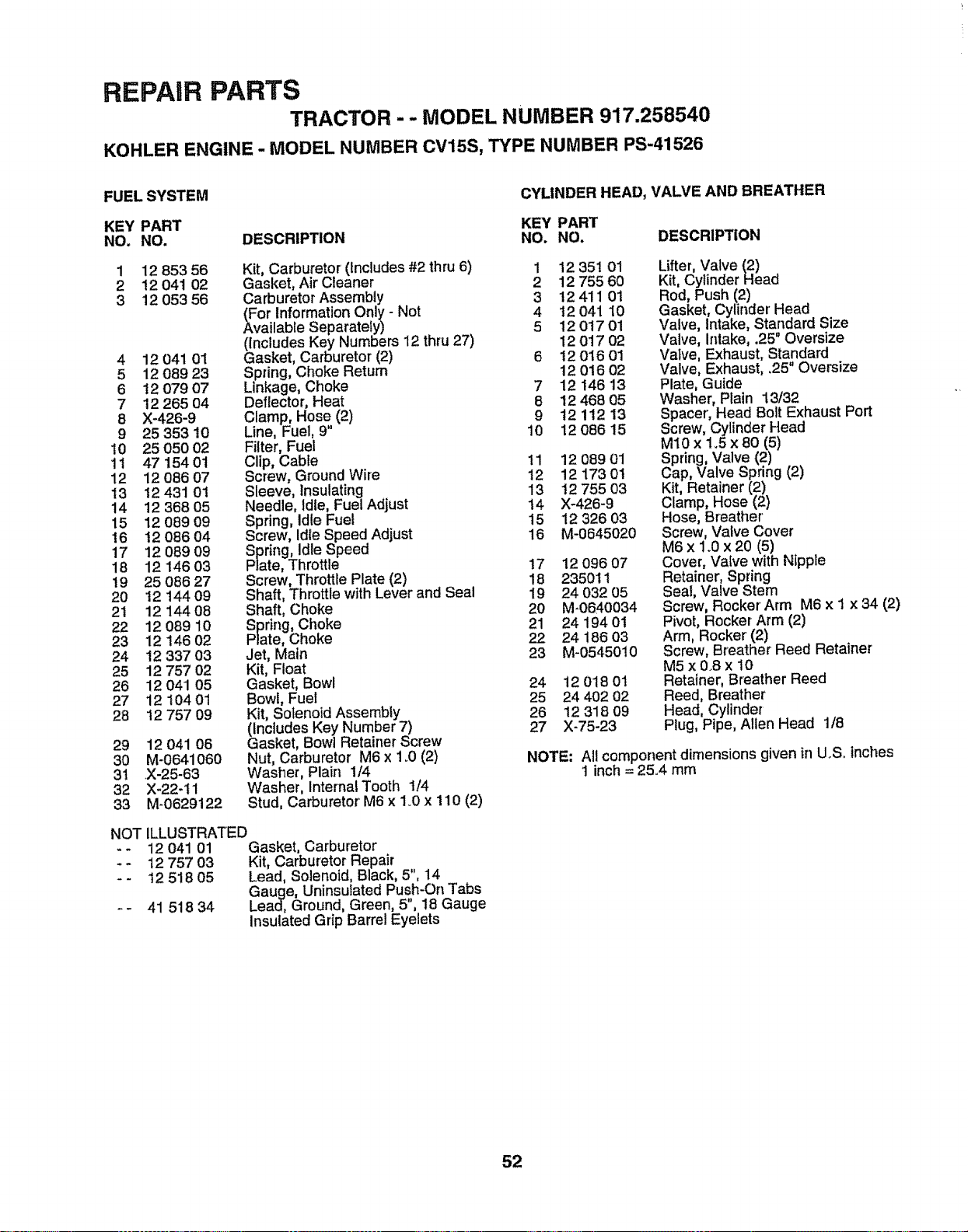
REPAIR PARTS
TRACTOR - - MODEL NUMBER 917.258540
KOHLER ENGINE - MODEL NUMBER CV15S, TYPE NUMBER PS-41526
FUEL SYSTEM
CYLINDER HEAD, VALVE AND BREATHER
KEY PART KEY PART
NO. NO. DESCRIPTION NO. NO. DESCRIPTION
12 853 56
12 041 02
12 053 56
1
2
3
4 12 041 01
5 12 08923
6 12 079 07
7 12 265 04
8 X-426-9
9 25 353 10
!0 25 050 02
11 4715401
12 12 086 07
13 12 431 01
t4 12 368 O5
15 12 089 09
16 t2 086 04
17 12 089 09
18 12 146 03
19 25 086 27
20 12 144 09
21 12 144 08
22 12 089 10
23 12 146 02
24 12 337 03
25 12 757 02
26 12 041 05
27 12 104 01
28 12 757 09
Kit, Carburetor (Includes #2 thru 6) 1
Gasket, Air Cleaner 2
Carburetor Assembly 3
(For Information Only - Not 4
Available Separately) 5
(Includes Key Numbers 12 thru 27)
Gasket, Carburetor (2) 6
Spring, Choke Return
Linkage, Choke 7
Deflector, Heat 8
Clamp, Hose (2) 9
Line, Fuel, 9" 10
Filter, Fuel
Clip, Cable 11
Screw, Ground Wire t2
Sleeve, Insulating 13
Needle, Idle, Fuel Adjust 14
Spring, Idle Fue! 15
Screw, Idle Speed Adjust 16
Spring, Idle Speed
Plate, Throttle 17
Screw, Throttle Plate (2) 18
Shaft, Throttle with Lever and Seal 19
Shaft, Choke 20
Spring, Choke 21
Plate, Choke 22
Jet, Main 23
Kit, Float
Gasket, Bowl 24
Bowl, Fuel 25
Kit, Solenoid Assembly 26
(Includes Key Number 7) 27
Gasket, Bowl Retainer Screw
Nut, Carburetor M6 x 1_0 (2)
Washer, Plain 1/4
Washer, Interna! Tooth 1/4
Stud, Carburetor M6 x 1.0 x 110 (2)
29 12 041 06
30 M-0641060
3t X-25-63
32 X-22-11
33 M-0629122
ILLUSTRATED
12 041 01 Gasket, Carburetor
12 757 03 Kit, Carburetor Repair
12 518 05 Lead, Solenoid, Black, 5", 14
Gauge, Uninsutated Push-On Tabs
41 518 34 Lead, Ground, Green, 5,18 Gauge
Insulated Grip Barrel Eyelets
NOT
12 351 01
12 755 60
12411 01
t2 041 I0
12 017 01
12 017 02
12 016 01
12 016 02
12 i46 13
12 468 05
12 112 13
12 086 15
12 089 01
12 173 0!
12 755 03
X-426-9
12 326 03
M-0645020
12 096 07
235011
24 032 05
M-0640034
24 194 01
24 186 03
M-0545010
12 018 0t
24 402 02
12 318 09
X-75-23
Lifter, Valve (2)
Kit, Cylinder Head
Rod, Push (2)
Gasket, Cylinder Head
Valve, Intake, Standard Size
Valve, Intake, ,25" Oversize
Valve, Exhaust, Standard
Valve, Exhaust, .25" Oversize
Plate, Guide
Washer, Plain 13/32
Spacer', Head Bolt Exhaust Port
Screw, Cylinder Head
M10 x 1_5x 80 (5)
Spring, Valve (2)
Cap, Valve Spring (2)
Kit, Retainer (2)
Clamp, Hose (2)
Hose, Breather
Screw, Valve Cover
M6 x 1.0 x 20 (5)
Cover, Valve with Nipple
Retainer, Spring
Seal, Valve Stem
Screw, Rocker'Arm M6 x I x 34 (2)
Pivot, Rocker Arm (2)
Arm, Rocker (2)
Screw, Breather' Reed Retainer
M5 x 0.8 x 10
Retainer, Breather Reed
Reed, Breather
Head, Cylinder
Plug, Pipe, Allen Head 1/8
NOTE: All component dimensions given in U.S, inches
t inch = 25.4 mm
52
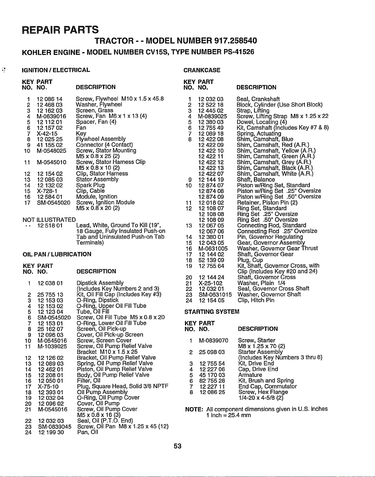
REPAIR PARTS
TRACTOR - - MODEL NUMBER 917.258540
KOHLER ENGINE - MODEL NUMBER CV15S, TYPE NUMBER PS-41526
IGNITION / ELECTRICAL CRANKCASE
KEY PART KEY PART
NO. NO_ DESCRIPTION NO. NO. DESCRIPTION
1 12 086 14 Screw, Flywheel M10 x 1_5x 45.8 1 12 032 03
2 12 46803 Washer, Flywheel 2 12 522 18
3 t2162 03 Screen, Grass 3 12 445 02
4 M-0639016 Screw, Fan M6x I x I3 (4) 4 M-0839025
5 12 112 01 Spacer, Fan (4) 5 12 380 03
6 1215702 Fan 6 1275549
7 X-42-15 Key 7 12 089 18
8 12 025 25 Flywheel Assembly 8 12 422 08
9 41 155 02 Connector (4 Contact) 12 422 09
10 M-0548025 Screw, Stator Mounting 12 422 10
M5 x 0°8 x 25 (2) 12 422 11
11 M-0545010 Screw, Stator Harness Clip 12 422 12
M5 x 0_8 x 10 (2) 12 422 13
12 12 '154 02 CIip, Stator Harness 12 422 07
13 12 085 03 Stator Assembly 9 12 144 19
14 12 132 02 Spark Plug 10 12 874 07
t5 X-728-1 Clip, Cable 12 874 08
16 12 584 01 Module, Ignition 12 874 09
17 SM-0545020 Screw, IgnitionModule 11 12 018 02
M5 x 0°8 x 20 (2) 12 12 108 07
12 108 08
NOT ILLUSTRATED 12 108 09
- - 12 5t8 01 Lead, White, Ground To Kill (19", 13 12 067 05
!8 Gauge, Fully Insulated Push-on 12 067 06
Tab and Uninsulated Push-on Tab 14 12 380 01
Terminals) 15 12 043 05
16 M-0631005
OIL PAN / LUBRICATION 17 12 144 02
18 52 139 09
KEY PART 19 12 755 64
NO. NO, DESCRIPTION
12 038 01
2 25755 13
3 12 153 03
4 12 153 02
5 12 12304
6 SM_0545020
7 t2 15301
8 25 162 07
9 t209603
10 M-0545016
!1 M-1039025
12 12 126 02
13 1208903
14 12 462 01
15 122O8O1
16 12 050 01
17 X-75_10
18 12 393 01
19 '12 032 04
2O 12 096 02
21 M-0545016
Dipstick Assembly
(Includes Key Numbers 2 and 3)
Kit, Oil Fill Cap (Includes Key #3)
O-Ring, Dipstick
O-Ring, Upper Oil Fill Tube
Tube, Oil Fill
Screw, Oil Flit Tube M5 x 0.8 x 20
O-Ring, Lower Oil Fill Tube
Screen, Oil Pick-up
Cover, Oil Pick-up Screen
Screw, Screen Cover
Screw, Oil Pump Relief Valve
Bracket M10 x 1.5 x 25
Bracket, Oil Pump Relief Valve
Spring, Oil Pump Relief Valve
Piston, Oil Pump Relief Valve
Body, Oil Pump Relief Valve
Filter, Oil
Plug, Square Head, Solid 3/8 NPTF
Oil Pump Assembly
O-Ring, Oil Pump Cover
Cover, Oil Pump
Screw, Oil Pump Cover
M5 x 0.8 x 16 (3)
Seal, Oil (P.ToO. End)
Screw, Oil Pan M8 x to25 x 45 (12)
Pan, Oil
22 12 032 03
23 SM-0839045
24 12 t99 30
20 12 144 24
21 X-25-102
22 12 032 01
23 SM-0631015
24 12'154 05
Seal, Crankshaft
Block, Cylinder (Use Short Block)
Strap, Lifting
Screw, Lifting Strap M8 x 1_25x 22
Dowel, Locating (4)
Kit, Camshaft (includes Key #7 & 8)
Sprin l, Actuating
Shim Camshaft, Blue
Shim Camshaft, Red (A.R.)
Shim Camshaft, Yellow (AR.)
Shim Camshaft, Green (A.R_)
Shim Camshaft, Grey (A.R.)
Shim Camshaft, Black (A,Ro)
Shim Camshaft, White (A.Ro)
Shaft Balance
Piston w!Ring Set, Standard
Piston wiRing Set .25" Oversize
Piston w/Ring Set .50" Oversize
Retainer, Piston Pin (2)
Ring Set, Standard
Ring Set .25" Oversize
Ring Set .50" Oversize
Connecting Rod, Standard
Connecting Rod °25" Oversize
Pin, Governor Regulating
Gear, Governor Assembly
Washer, Governor Gear Thrust
Shaft, Governor Gear
Plug, Cup
Kit, Shaft, Governor Cross, with
Clip (Includes Key #20 and 24)
Shaft, Governor Cross
Washer, Plain 1/4
Seal, Governor Cross Shaft
Washer, Governor Shaft
Clip, Hitch Pin
STARTING SYSTEM
KEY PART
NO, NO. DESCRIPTION
1 M-0839070 Screw, Starter
M8 x 1o25x 70 (2)
2 25 098 03 Starter Assembly
(Includes Key Numbers 3 thru 8)
3 12 75554 Kit, Drive End
4 12 227 06 Cap, Drive End
5 45 170 03 Armature
6 82 755 28 Kit, Brush and Spdng
7 12 227 11 End Cap, Commutator
8 12 086 25 Screw, Hex Flange
I/4-20 x 4-5/8 (2)
NOTE: All component dimensions given in UoSoinches
1 inch = 25,4 mm
53

i i i i i i llllll
E
54

SUGGESTED GUIDE FOR SIGHTING SLOPES FOR SAFE OPERATION
SIGHTING "" .-.-
ONLY RIDE UP AND DOWN HILL,
NOT ACROSS HILL
SIGHT AND HOLD THIS LEVEL WITH
SKY LINE OR TREE.
/
15 ° MAX.
OWNER'S
MANUAL
MODEL NO.
917.258540
IF YOU NEED
REPAIR SERVICE
OR PARTS:
FOR REPAIR SERVICE, CALL
THIS TOLL FREE NUMBER:
1-800-4-REPAIR
(1-800-473°7247)
FOR REPLACEMENT PARTS
INFORMATION AND
ORDERING, CALL THIS
TOLL FREE NUMBER:
1-800-FON-PART
(1-800-366-7278)
FOR CONSUMER ASSISTANCE
HOT LINE, CALL THIS
TOLL FREE NUMBER:
1-800-659-5917
£RI FT/MaN ®
15.0 HP
ELECTRIC START
42" MOWER
6 SPEED TRANSAXLE
LAWN TRACTOR
Each tractor has its own model number° Each engine has
its own model number°
The model number for your tractor will be found on the
model plate located under the seat,
The model number for your engine will be found on the
blower housing of the engine.
All pads listed herein may be ordered from any Sears,
Roebuck and Coo Service Center/Department and most Re-
tail Stores.
WHEN ORDERING REPAIR PARTS, ALWAYS GIVE THE
FOLLOWING INFORMATION:
" PRODUCT" TRACTOR
" MODEL NUMBER " 917.258540
• ENGINE MODEL NO. " CV15S TYPE NO. PS'41526
" PART NUMBER
• PART DESCRIPTION
Your Sears merchandise has added value when you
consider Sears has service units nationwide staffed with
Sears trained technicians ......professional technicians
specifically trained to insure that we meet our pledge to
you, we service what we sel!.
156790 Rew, 3 01.29,97 BW/KFSW/TRtKFSW Printed in U,,SoA,


