
Owner's Manual
JCRRFTSMRN'J
20.0 HP
ELECTRIC START
46" MOWER
AUTOMATIC
GARDEN TRACTOR
Model No.
917.272960
EZ3
• Safety
• Assembly
• Operation
• Maintenance
• Repair Parts
This product has € low emission engine which Operates
differently from prey ous y built engines. Before you start the
engine, read and understand this Owner's Manual.
CAUTION:
Read and follow all Safety
Rules and Instructions before
operating this equipment.
For answers to your questions
about this product, Call:
1-800-659-5917
Sears Craftsman Help Line
5 am - 5 pro, Mon- Set
Sears, Roebuck and Co., Hoffman Estates, II 60179
Visitour Craftsman website:www.sears.com/craftsman
Warranty............................................... 2
Safety Rules .........................................3
Product Specifications.......................... 5
Assembly ..............................................7
Operation ............................................ 12
Maintenance Schedule...................... 19
Maintenance .......................................19
Serviceand Adjustments....................23
Storage ...............................................31
Troubleshooting .................................92
Repair Parts ........................................36
Parts Ordering .....................Back Cover
LIMITEDTWO YEAR WARRANTYON CRAFTSMAN RIDING EQUIPMENTPARTS
For two(2) years from the date of purchase, ifthis Craftsman Riding Equipment is
maintained, lubricated and tuned up according to the instructions in the owner's
manual, Sears willrepair or replace, free of charge, any parts found to be defective in
material or workmanship. Warranty serviceis available free of charge by taking your
Craftsman ddingequipmentto your nearest Sears Service Center. In-home warranty
service is available but a trip charge will apply. This warranty applies only while this
product is in the United States.
This Warranty does not cover:
• Expendable items whichbecome worn during normal use, such as blades, spark
plugs, air cleaners, belts and oilfilters,
• Tire replacementor repair causedby punctures from outside objects, such as nails,
thorns, stumps,or glass.
• Repairs necessarybecause of operator abuse, including but not limited to, damage
caused by towing objects beyond the capability of the dding equipment,impacting
objects that bend the frame or crankshaft,or over speedingthe engine.
• Repairs necessarybecause of operator negligence, including but not limited to,
electricaland mechanical damage caused by improper storage, failure to use the
proper grade and amount of engineoil,failure to keep the deck clear of flammable
debris, or the failure to maintainthe equipment according to the instructions con-
tained in the owner's manual.
• Engine (fuel system)cleaningor repairs caused by fuel determined to be contami-
nated or oxidized (stale). In general, fuel shouldbe used within thirty (30) days of its
purchase date.
• Riding equipment used for commercial or rental purposes.
LIMITED 90 DAYWARRANTY ON BATTERY
Forninety (90) daysfromdate ofpurchase,ifany batteryincludedwiththisriding
equipmentprovesdefectivein materialor workmanshipand ourtestingdeterminesthe
batterywillnot holda charge,Sears willreplacethe batteryat nocharge.Warranty
serviceis availablefree ofchargeby takingyourCraftsmanddingequipmenttoyour
nearestSears ServiceCenter. In-homewarrantyserviceisavailablebut a tripcharge
willapply.Thiswarrantyappliesonlywhilethis productis inthe UnitedStates.
To locatethe nearestsears servicecenteror to schedulein-homewarrantyservice,
simplycontactsears at 1-800-4-my-home
ThisWarrantygivesyou specificlegalrights,and youmay alsohave otherrightswhich
mayvaryfrom statetostate.
Sears, Roebuck and Co., D/817 WA, Hoffman Estates, IL 60179

IMPORTANT:Thiscuttingmachineis
capableof amputatinghands and feet
andthrowingobjects.Failureto observe
the following safetyinstructionscould
resultinseriousinjuryor death.
GENERAL OPERATION
• Read, understand,and follow all
instructionsin the manualand on the
machinebeforestarting.
• Only allowresponsibleadults,who are
familiar withthe instructions,tooperate
the machine.
• Clearthearea ofobjectssuchas recks,
toys,wire,etc., whichcouldbe picked
up and thrownby theblade.
• Besurethe areaisclear ofother
peoplebeforemowing.Stop machineif
anyoneentersthe area.
• Never carrypassengers.
• Do not mowin reverseunlessabsolute-
lynecessary.Alwayslookdownand
behindbeforeand while backing.
• "Be awareofthe mowerdischarge
directionand de notpointit at anyone.
Do not operatethemowerwithout
eithertheentiregrasscatcherorthe
guardin place.
• Slowdownbeforeturning.
• Never leave a runningmachine
unattended.Alwaysturnoffblades,set
parkingbrake,stop engine,and remove
keys beforedismounting.
• Turnoffbladeswhen not mowing.
• Stop enginebefore removinggrass
catcheror uncloggingchute.
• Mow onlyindaylightor goodartificial
light.
• Do not operate the machinewhile
underthe influenceof alcoholor drugs.
• Watchfor trafficwhenoperatingnearor
crossingroadways.
• Use extracarewhen loadingor
unloadingthe machineintoa traileror
truck.
• Data indicatesthatoperators,age 60
yearsand above,are involvedin a
largepercentage of ridingmower-
relatedinjuries.These operatorsshould
evaluatetheirabilityto operatethe
ridingmowersafelyenoughto protect
themselvesand othersfrom serious
injury.
SLOPEOPERATION
Slopesarea majorfactorrelatedto loss-
of-controland tipoveraccidents,which
can resultinsevereinjuryor death.All
slopesrequireextracaution.Ifyoucannot
backupthe slopeor ifyoufeel uneasyon
it,do notmowit.
DO:
• Mow upand downslopes,notacross.
• Removeobstaclessuchas rocks,tree
limbs,etc.
• Watchfor holes,ruts,or bumps.Uneven
terraincouldoverturnthemachine.Tall
grasscan hideobstacles.
• Useslowspeed.Choosea lowgear so
thatyouwillnothavetostopor shift
whileon the slope.
• Followthe manufacturer'srecommen-
dationsfor wheelweightsor counter-
weightsto improvestability.
• Useextracarewithgrasscatchersor
otherattachments.These canchange
the stabilityofthemachine.
• Keepall movementon the slopesslow
and gradual.Do not makesudden
changesin speed or direction.
• Avoidstartingor stoppingon a slope.If
tireslose traction,disengagethe blades
and proceedslowlystraightdownthe
slope.
DONOT:
• Do notturn on slopesunlessneces-
sary, and then,turnslowlyand gradual-
lydownhill,ifpossible.
• Do notmowneardrop-offs,ditches,or
embankments.The mowercould
suddenlyturnoverifa wheelis overthe
edgeofa cliffor ditch,or ifan edge
caves in.
• Do not mowon wet grass.Reduced
tractioncouldcause sliding.
• Donottrytostabilizethemachineby
puttingyourfoot on the ground.
• Do notusegrasscatcheron steep
slopes.
CHILDREN
Tragicaccidentscan occuriftheoperator
isnotalerttothepresenceofchildren.
Childrenareoften attractedtothe
machineand the mowingactivity.Never
assumethat childrenwillremainwhere
youlastsaw them.
• Keepchildrenout ofthe mowingarea
and underthe watchfulcare ofanother
responsibleadult.
• Be alertandtum machineoffifchildren
enterthe area.
3
• Beforeandwhenbacking,lookbehind
anddownforsmall children.
• Nevercarrychildren.They may fall off
and be seriouslyinjuredor interfere
withsafe machine operation.
• Never allowchildrentooperatethe
machine.
• Use extra care when approaching blind
corners,shrubs,trees,or otherobjects
thatmay obsGurevision.
SERVICE
• Use extracare in handlinggasoline
and otherfuels. They are flammable
and vaporsare explosive.
Use onlyan approvedcontainer.
- Never removegascap or add fuel
with theengine running.Allow
enginetocoolbeforerefueling.Do
notsmoke.
- Never refuelthe machineindoors.
- Never storethe machineor fuel
container inside where there is an
openflame, suchas a waterheater.
• Never runa machineinsidea closed
area,
• Keep nutsand bolts,especiallyblade
attachmentbolts,tightand keep
equipmentin good condition.
• Nevertamperwithsafetydevices.
Checktheirproperoperationregulady.
• Keep machinefree of grass,leaves,or
otherdebrisbuild-up.Cleanoil or fue_
spillage.Allowmachineto coolbefore
storing.
• Stopand inspect the equipment if you
strikean object.Repair,ifnecessary,
beforerestarting.
• Never make adjustments or repairs
withthe engine running.
• Grasscatchercomponentsare subject
to wear, damage,and deterioration,
whichcouldexposemovingpartsor
allowobjectsto bethrown.Frequently
checkcomponentsand replace with
manufacturer's recommendedparts,
when necessary.
• Mowerblades are sharpand cancut.
Wraptheblade(s) or wear gloves,and
use extra cautionwhenservicing
them.
• Check brake operationfrequently.
Adjustandserviceas required.
• Be sure the area is clear of other
people before mowing. Stop machine
if anyone enters the area.
• Never carry passengers or children
even with the blades off.
• Do not mow in reverse unless abso-
lutely necessary. Always look down
and behind before and while backing,
• Never carry chiktren. They may fall off
and be seriously injured or interfere
with safe machine operation.
• Keep children out of the mowing area
and under the watchful care of another
responsible adult.
• Be alert and turn machine off if
children enter the area.
• Before and when backing, look behind
and down for small children.
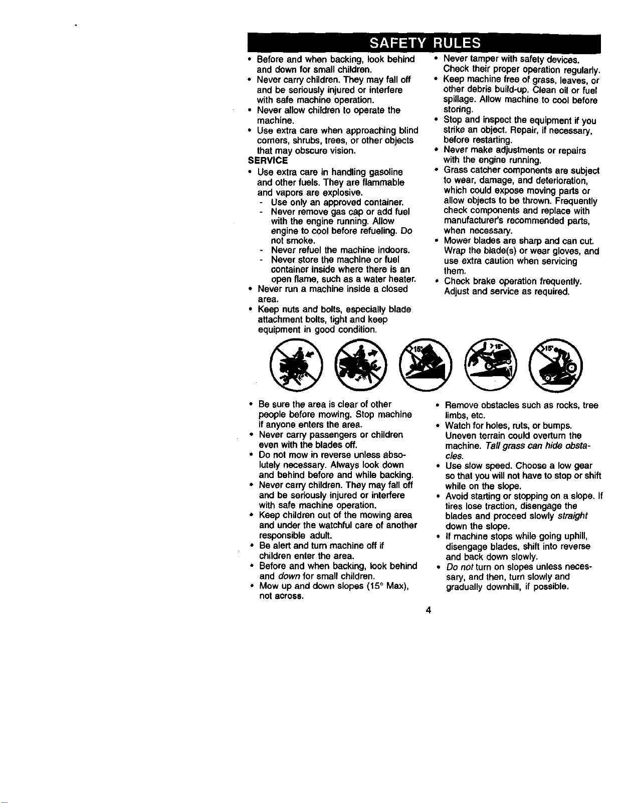
• Mow up and down slopes (15 ° Max),
not across,
• Removeobstaclessuchas rocks,tree
limbs,etc.
• Watchforholes,ruts,or bumps.
Uneventerraincouldoverturnthe
machine.TailgrasScan hideobsta-
cles.
• Use slowspeed.Choosea lowgear
sothatyouwillnothaveto stopor shift
whileonthe slope.
• Avoidstartingor stoppingona slope.If
tireslosetraction,disengagethe
bladesand proceedslowlystraight
downthe slope.
• It machinestopswhilegoinguphill,
disengageblades,shiftintoreverse
and backdownslowly.
• Do notturn on slopesunlessneces-
saw, and then,turnslowlyand
graduallydownhill,if possible.
4
_lLLook for this symbol to point out
important safety precautions. It means
CAUTION!H BECOMEAWARE!!! YOUR
,_FETY IS INVOLVED.
CAUTION: In order to prevent
accidental starting when setting up,
transporting, adjusting or making repairs
always disconnect spark plug wire and
place wire where it cannot contact spark
g.
P_CAUTION: Do not coast down a hill in
neutral, you may lose control of the
tractor.
A_I,CAUTION: Tow only the attachments
that are recommended by and comply
with specifications of the manufacturer of
your tractor, Use common sense when
towing. Operate only at the lowest
possible speed when on a slope, Too
heavy of a load, while on a slope, is
dangerous, Tires can lose traction with the
ground and cause you to lose control of
Y_Uwrtractor.
ARNING: The engine exhaust from
this product contains chemicals known to
the State of California to cause cancer,
birth defects, or other reproductive harm.
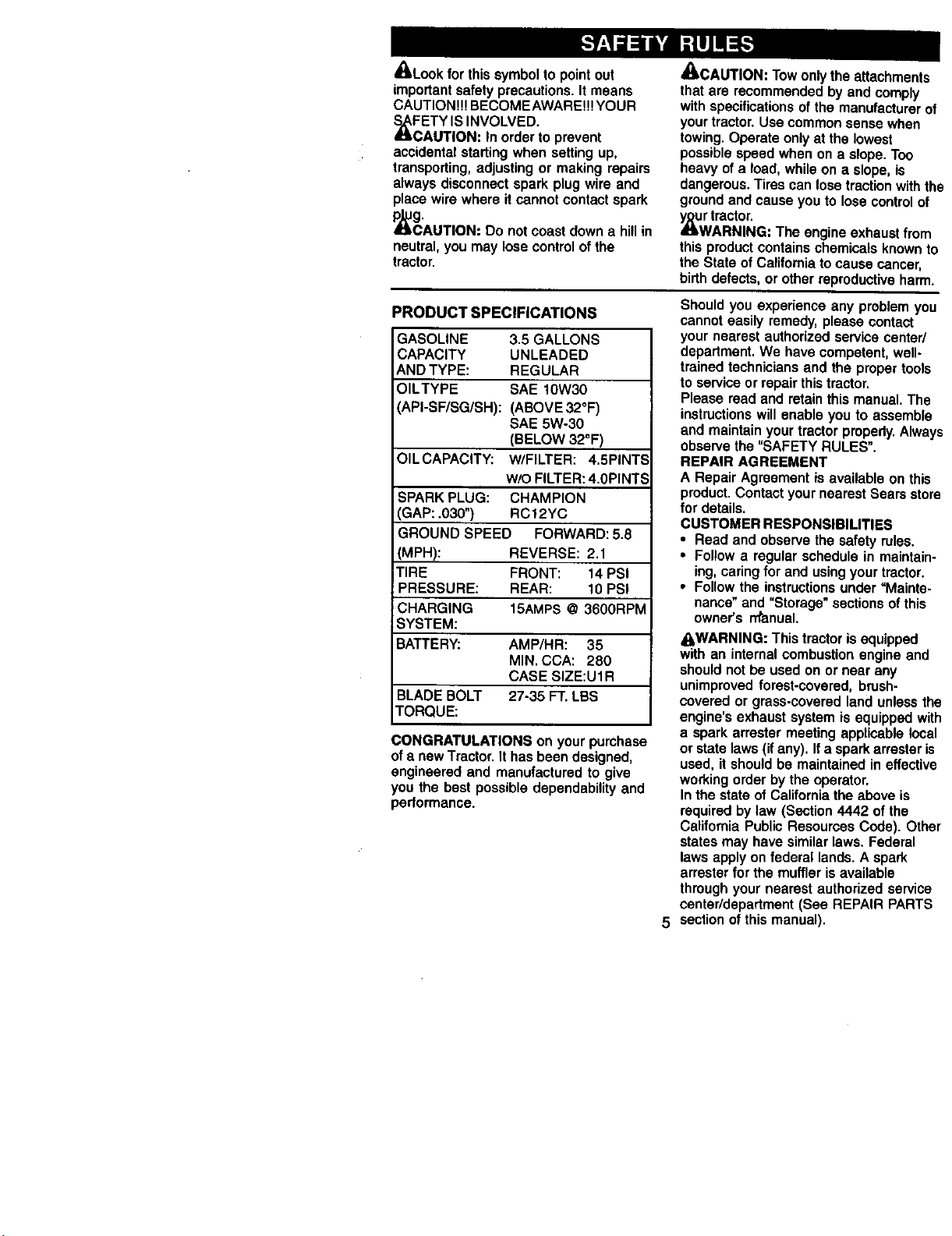
PRODUCT SPECIFICATIONS
GASOLINE 3.5 GALLONS
CAPACITY UNLEADED
AND TYPE: REGULAR
OILTYPE SAE 10W30
_PI-SF/SG/SH): (ABOVE 32°F)
SAE 5W-30
(BELOW 32°F)
OILCAPACITY: W/FILTER: 4.5PINTS
WiO FILTER: 4.0PINTS
SPARK PLUG: CHAMPION
.3AP: .030") RC12YC
GROUND SPEED FORWARD: 5.8
(MPH): REVERSE: 2.1
TIRE FRONT: 14 PSI
PRESSURE: REAR: 10 PSI
CHARGING 15AMPS @ 3600RPM
SYSTEM:
BATTERY: AMP/HR: 35
MIN. CCA: 280
CASE SIZE:U1R
BLADE BOLT 27-35 FT. LBS
TORQUE:
CONGRATULATIONS on your purchase
of a new Tractor. It has been designed,
engineered and manufactured to give
you the best possible dependability and
performance.
5
Should you experience any problem you
cannot easily remedy, please contact
your nearest authorized service center/
department, We have competent, well-
trained technicians and the proper tools
to service or repair this tractor,
Please read and retain this manual, The
instructions will enable you to assemble
and maintain your tractor propedy, Always
observe the "SAFETY RULES".
REPAIR AGREEMENT
A Repair Agreement is available on this
product. Contact your nearest Sears store
for details.
CUSTOMER RESPONSIBILITIES
• Read and observe the safety rules.
• Follow a regular schedule in maintain-
ing, caring for and using your tractor.
• Follow the instructions under =Mainte-
nance" and "Storage" sections of this
owner's rrtanual.
_WARNING: This tractor is equipped
with an internal combustion engine and
should not be used on or near any
unimproved forest-covered, brush-
covered or grass-covered land unless the
engine's exhaust system is equipped with
a spark arrester meeting applicable local
or state laws (if any). If a spark arraster is
used, it should be maintained in effective
working order by the operator.
In the state of California the above is
required by law (Section 4442 of the
California Public Resources Code). Other
states may have similar laws. Federal
laws apply on federal lands. A spark
arrester for the muffler is available
through your nearest authorized service
center/department (See REPAIR PARTS
section of this manual).
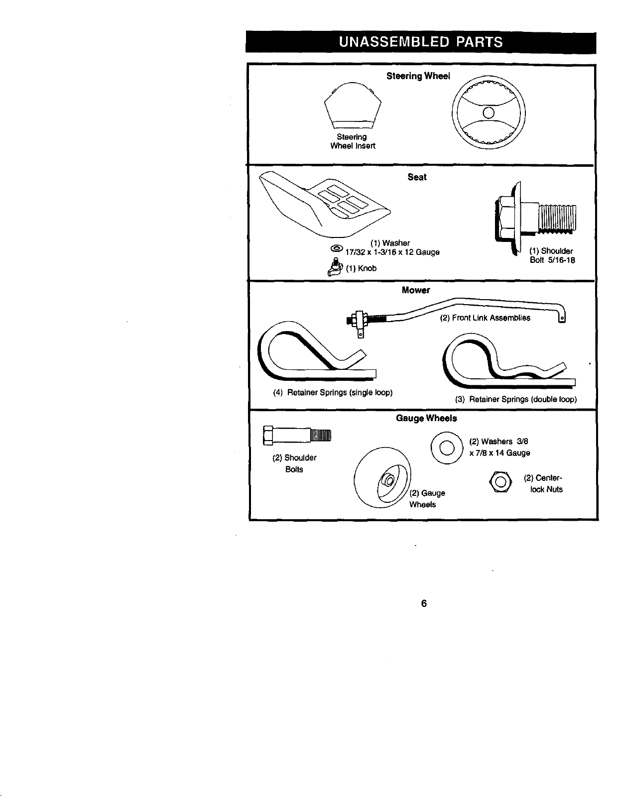
Steedng
Wheel Insert
Steering Wheel
Seat
(1) Washer
(_) 17/32 x 1-3/16 x 12 Gauge (1) Shoulder
Bolt 5/16-18
i_(1) Knob
Mower
(4) Retainer Springs (single loop)
(3) Retainer Springs (double loop)
Gauge Wheels
(2) Shoulder x 7/8 x 14 Gauge
Bolts
Q (2) Center-
lockNuts
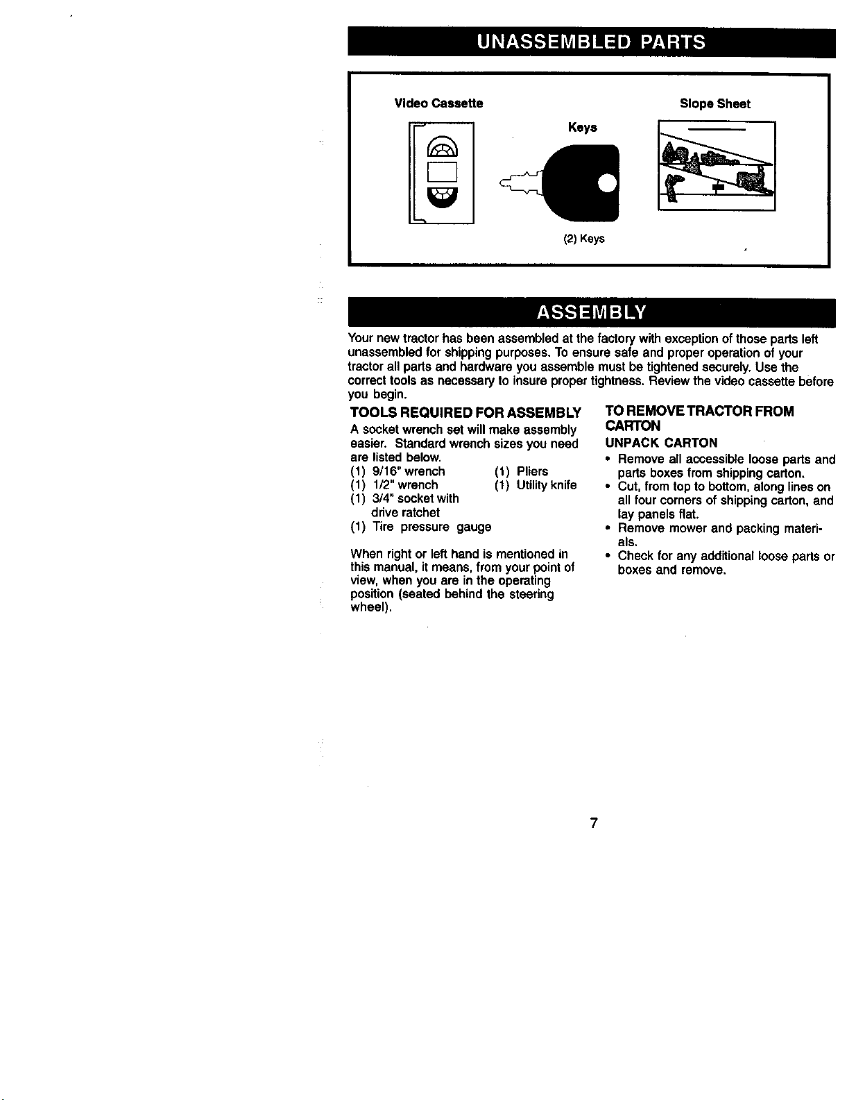
VideoCeeee_e
_m
Keys
(2) Keys
Slope Sheet
Yournewtractorhas beenassembledat thefactorywithexceptionofthosepartsleft
unassembledfor shippingpurposes.To ensuresafe and properoperationof your
tractorallpartsand hardwareyouassemblemustbe tightenedsecurely.Use the
correcttoolsas necessaryto insurepropertightness.Reviewthe videocassettebefore
you begin.
TOOLS REQUIRED FOR ASSEMBLY
A socketwrenchsetwillmake assembly
easier. Standardwrenchsizesyou need
are listedbelow.
(1) 9/16"wrench (1) Pliers
(1) 1/2"wrench (1) Utilityknife
(1) 3/4"socketwith
driveratchet
(1) Tire pressure gauge
When rightor lefthandismentionedin
thismanual,itmeans,fromyourpointof
view,when youare inthe operating
position(seatedbehindthe steering
wheel).
TO REMOVE TRACTOR FROM
CARTON
UNPACK CARTON
• Remove all accessible loose parts and
parts boxes from shipping carton,
• Cut, from top to bottom, along lines on
all four corners of shipping carton, and
lay panels flat.
• Remove mower and packing materi-
als.
• Check for any additional loose parts or
boxes and remove,
7
BEFOREREMOVINGTRACTOR
OFFSKID
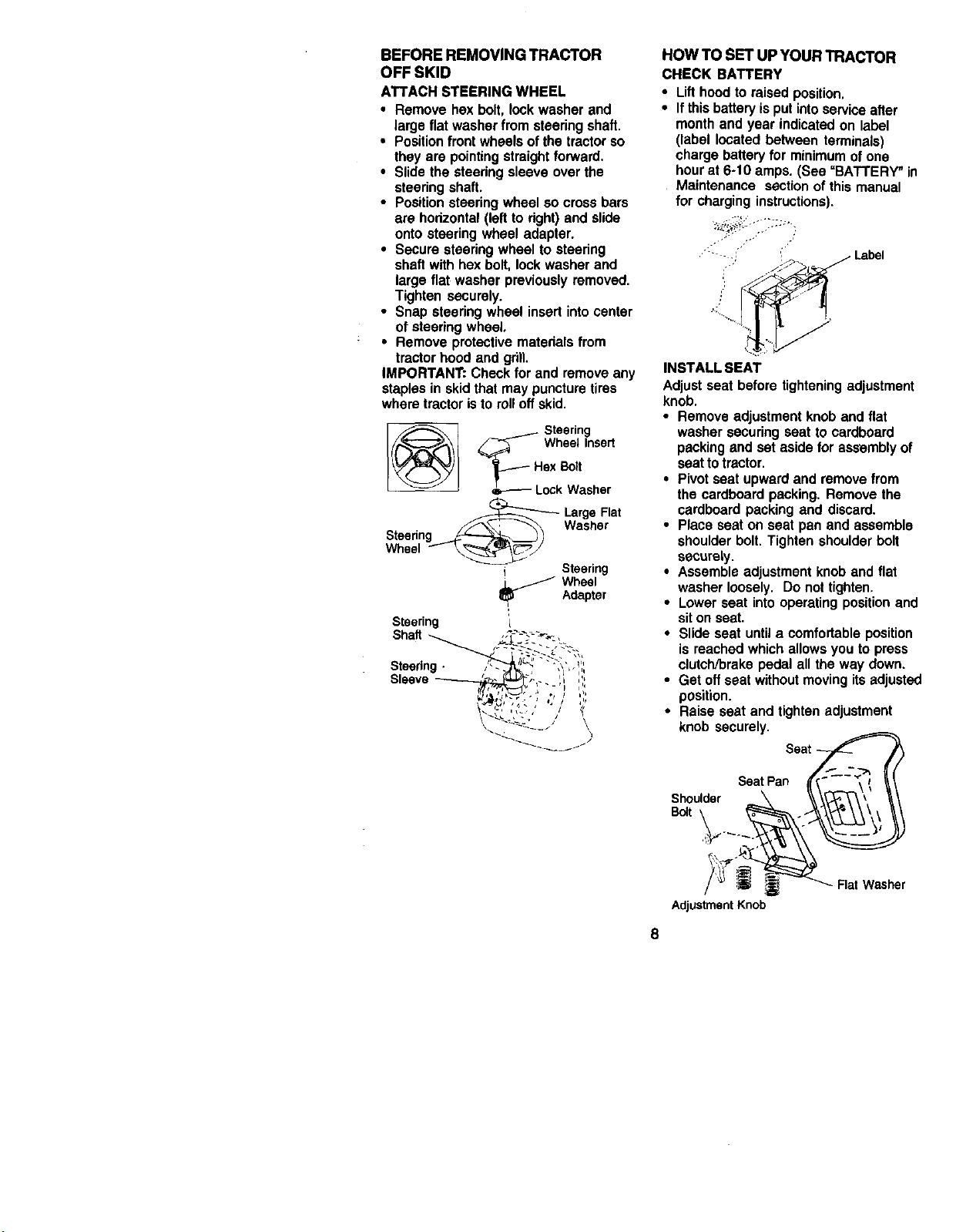
ATTACHSTEERINGWHEEL
• Removehexbolt,lockwasherand
largeflatwasherfromsteeringshaft.
• Positionfrontwheelsofthetractorso
they are pointingstraightforward.
• Slidethesteedngsleeveover the
steeringshaft,
• Positionsteeringwheelso crossbars
are horizontal(leftto dght)and slide
ontosteeringwheel adapter,
• Secure steeringwheelto steering
shaftwithhexbolt,lockwasherand
largeflat washerpreviouslyremoved.
Tightensecurely.
• Snap steeringwheel insertintocenter
of steeringwheel.
• Removeprotectivematedalsfrom
tractorhoodand gdlL
IMPORTANT:Checkfor and removeany
staplesin skidthatmay puncturetires
wheretractoristo rolloffskid.
_ Steering
_ Wheel Insert
_F_-- Hex I_:_t
Lock Washer
_ arge Flat
Washer
Steering
Wheel f _//
Steering
_ Wheel
, Adapter
Steering I
Shaft
Steering-
Sleeve
\ \
HOW TO SET UP YOUR TRACTOR
CHECK BATTERY
• Lifthoodto raisedposition.
• Ifthis battery isputinto serviceafter
monthand year indicatedon label
(label locatedbetween terminals)
chargebatteryfor minimumofone
hourat 6-10 amps. (See "BATTERY" in
Maintenance sectionof thismanual
for charginginstructions).
i
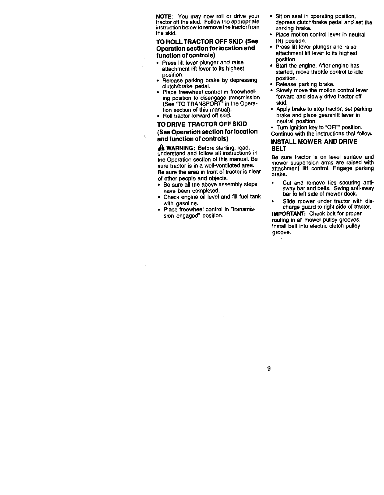
INSTALL SEAT
Adjustseat beforetighteningadjustment
knob.
• Removeadjustmentknoband flat
washersecuringseatto cardboard
packingand set aside for assemblyof
seatto tractor.
• Pivot seat upwardand remove from
the cardboardpacking.Remove the
cardboard packing and discard.
• Place seaton seat pan and assemble
shoulder bolt. Tighten shoulder bolt
SeCUrely.
• Assemble adjustment knob andflat
washer loosely. Do not tighten,
• Lower seat into operating position and
sit on seat.
• Slide seat until a comfortable position
is reached which allows you to press
clutch/brake pedal all the way down.
• Get off seatwithoutmoving its adjusted
position.
• Raiseseat and tighten adjustment
knob securely.
SeatPan
Shoulder
Bctt
Adjustment Knob
8
NOTE: You may now roll or drive your
tractor offthe skid. Follow the appropriate
instructionbelow toremove the tractor from
the skid.
TO ROLLTRACTOR OFF SKID (See
Operation section for location and
function of controls)
• Press lift lever plunger and raise
attachment lift lever to its highest
position.
• Release parking brake by depressing
clutch/brake pedal.
• Place freewheel control in freewheel-
ing position to disengage transmission
(See TO TRANSPORT" in the Opera-
tion section of this manual).
• Roll tractor forward off skid.
TO DRIVE TRACTOR OFF SKID
(See Operation section for location
and function of controls)
WARNING: Before starting read,
understand and follow all instruct ons in
the Operation section of this manual. Be
sure tractor is in a well-ventilated area.
Be sure the area in front of tractor is clear
of other people and objects.
• Be sure all the above assembly steps
have been completed.
• Check engine oil level and fill fuel tank
with gasoline.
• Place freewheel control in "transmis-
sion engaged" position.
• Sit on seat in operating position,
depress clutch/brake pedal and set the
parking brake.
• Place motion control lever in neutral
(N) position.
• Press lift lever plunger and raise
attachment lift lever to its highest
position.
• Start the engine. After engine has
started, move throttle control to idle
position.
• Release parking brake.
• Slowly move the motion control lever
forward and slowly drive tractor off
skid.
• Apply brake to stop tractor, set parking
brake and place gearshift lever in
neutral position.
• Turn ignition key to "OFF" position.
Continue with the instructions that follow.
INSTALL MOWER AND DRIVE
BELT
Be sure tractoris on level surface and
mower suspensionarmsare raisedwith
attachment lift control. Engage parking
brake.
• Cut and remove ties securing anti-
sway bar and belts. Swing anti-sway
bar to left side of mower deck.
• Slide mower under tractor with dis-
charge guard to right side of tractor.
IMPORTANT: Check belt for proper
routing in all mower pulley grooves.
Install belt into electric clutch pulley
groove.
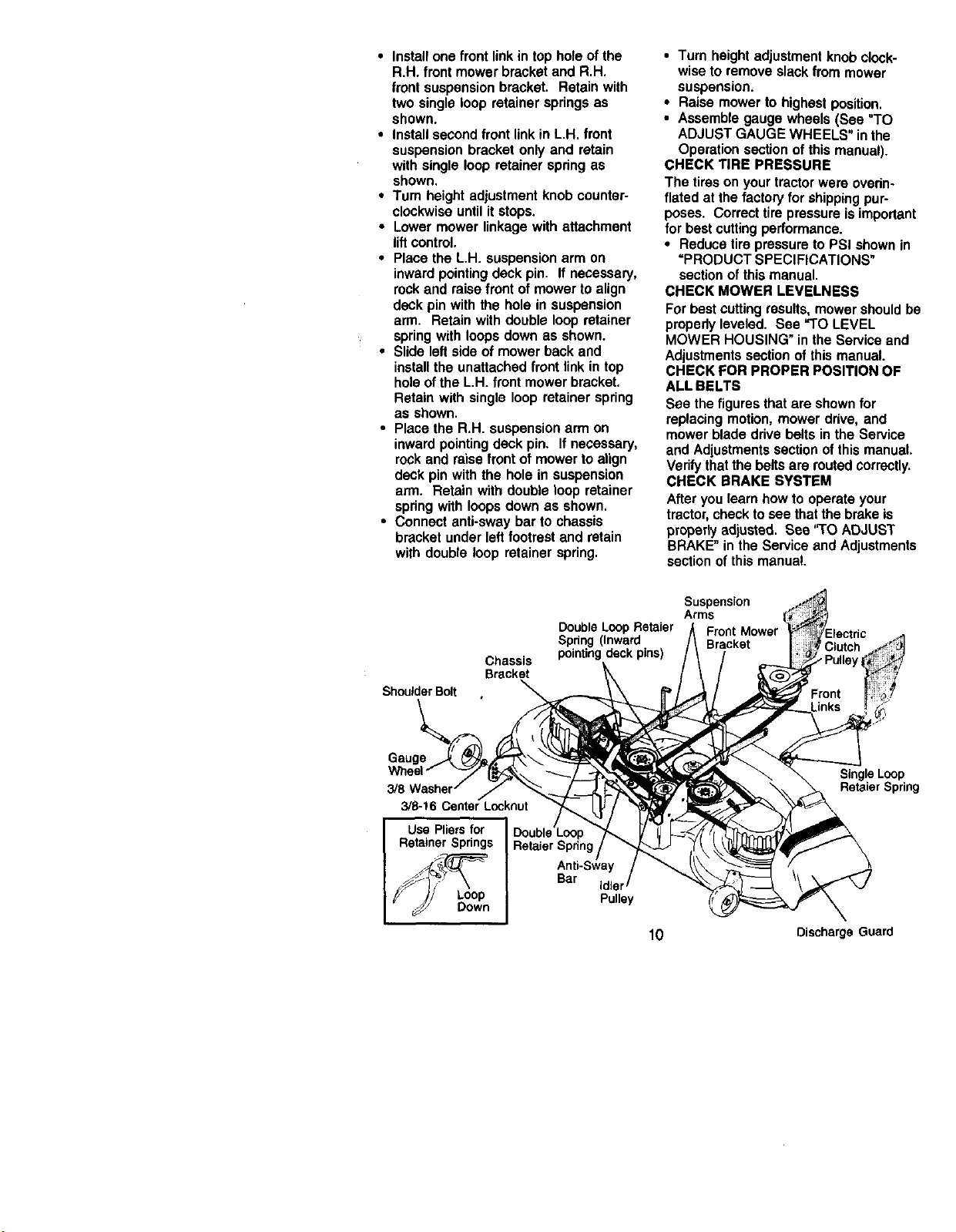
• Installone front linkin top holeofthe
R.H. front mowerbracketand R.H.
front suspensionbracket. Retainwith
twosingleloop retainerspringsas
shown.
• Installsecondfront linkin L.H. front
suspensionbracketonlyand retain
withsingleloop retainerspringas
shown,
•Tum heightadjustmentknobcounter-
clockwiseuntilitstops.
• Lowermowerlinkagewithattachment
liftcontrol.
• Placethe L.H. suspensionarm on
inwardpointingdeckpin. If necessary,
rockand raise front ofmowertoalign
deckpinwiththe holein suspension
arm. Retainwithdoubleloopretainer
springwith loopsdownas shown.
• Slideleftsideof mowerbackand
installthe unattachedfront linkin top
holeoftheL.H. front mowerbracket.
Retainwith singleloop retainerspring
as shown.
• Placethe R.H. suspensionarm on
inwardpointingdeck pin. If necessary,
rockand raisefrontof mowertoalign
deckpinwiththe holein suspension
arm. Retainwith doubleloopretainer
springwithloopsdownas shown.
• Connectanti-swaybar to chassis
bracketunderleftfootrest and retain
with doubleloop retainerspring.
•Tum height adjustment knob clock-
wise to remove slack from mower
suspension.
• Raise mower to highest position.
• Assemble gauge wheels (See "TO
ADJUST GAUGE WHEELS" in the
Operation section of this manual).
CHECK TIRE PRESSURE
The tires on your tractor were ovedn-
flated at the factory for shipping pur-
poses. Correct tire pressure is important
for best cutting performance.
• Reduce tire pressure to PSI shown in
=PRODUCT SPECIFICATIONS"
section of this manual.
CHECK MOWER LEVELNESS
For best cutting results, mower should be
propedy leveled. See _1"OLEVEL
MOWER HOUSING" in the Service and
Adjustments section of this manual.
CHECK FOR PROPER POSITION OF
ALL BELTS
See the figures that are shown for
replacing motion, mower drive, and
mower blade ddve belts in the Service
and Adjustments section of this manual.
Verify that the belts are routed correctly.
CHECK BRAKE SYSTEM
After you learn how to operate your
tractor, check to see that the brake is
propedy adjusted. See '_1"OADJUST
BRAKE" in the Service and Adjustments
section of this manual.
ShoulderBolt
Chassis
Bracket
Double Loop Retaier
Spring (Inward
pointing deck pins)
Suspension
Arms t
Front Mower
Bracket
3/8
3/8-16 Center Locknut
Use Pliersfor
RetainerSprings
y )/ Loop
_/// Down
Bar
Idler
Pulley
10
Single Loop
Retaier Spring
Discharge Guard
l/CHECKLIST
BEFORE YOU OPERATE AND ENJOY
YOUR NEW TRACTOR, WE WISH TO
ASSURE THAT YOU RECEIVE THE
BEST PERFORMANCE AND
SATISFACTION FROM THIS QUALITY
PRODUCT.
PLEASEREVIEWTHE FOLLOWING
CHECKLIST:
,/ Allassemblyinstructionshave been
completed.
4"No remainingloosepartsin carton.
4"Batteryis properlypreparedand
charged. (Minimum1 hourat 6
amps).
4"Seat is adjusted comfortablyand
tightenedsecurely.
4 Alltiresare properlyinflated. (For
shippingpurposes,the tireswere
overinflatedat thefactory).
,/' Besuremowerdeckis properly
• leveled side-to-sida/front-to-rearfor
bestcuttingresults. (Tiresmustbe
properlyinflatedfor leveling).
4 Checkmowerand drivebelts. Besure
they are routedproperlyaround
pulleysand insideall belt keepers.
4"Checkwiring. Sea thatall connections
are stillsecure and wiresare properly
clamped.
4 Beforedrivingtractor,be surefree-
wheel controlis in driveposition.
WHILE LEARNINGHOWTO USE YOUR
TRACTOR, PAYEXTRAATTENTIONTO
THE FOLLOWINGIMPORTANTITEMS:
,/Engine oi!isat properlevel.
4 Fue!tankisfilled withfresh, clean,
regular unleaded gasoline.
4"Becomefamiliar with allcontrols- their
locationand function. Operatethem
beforeyou startthe engine.
€"Besurebrakesystemisin safe
operating condition.
4' Itisimportanttopurgethe transmis-
sionbeforeoperatingyourtractorfor
thefirst time. Followproperstarting
and transmissionpurginginstructions
(See "TO START ENGINE"and
"PURGE TRANSMISSION"inthe
Operationsectionof thismanual).
11
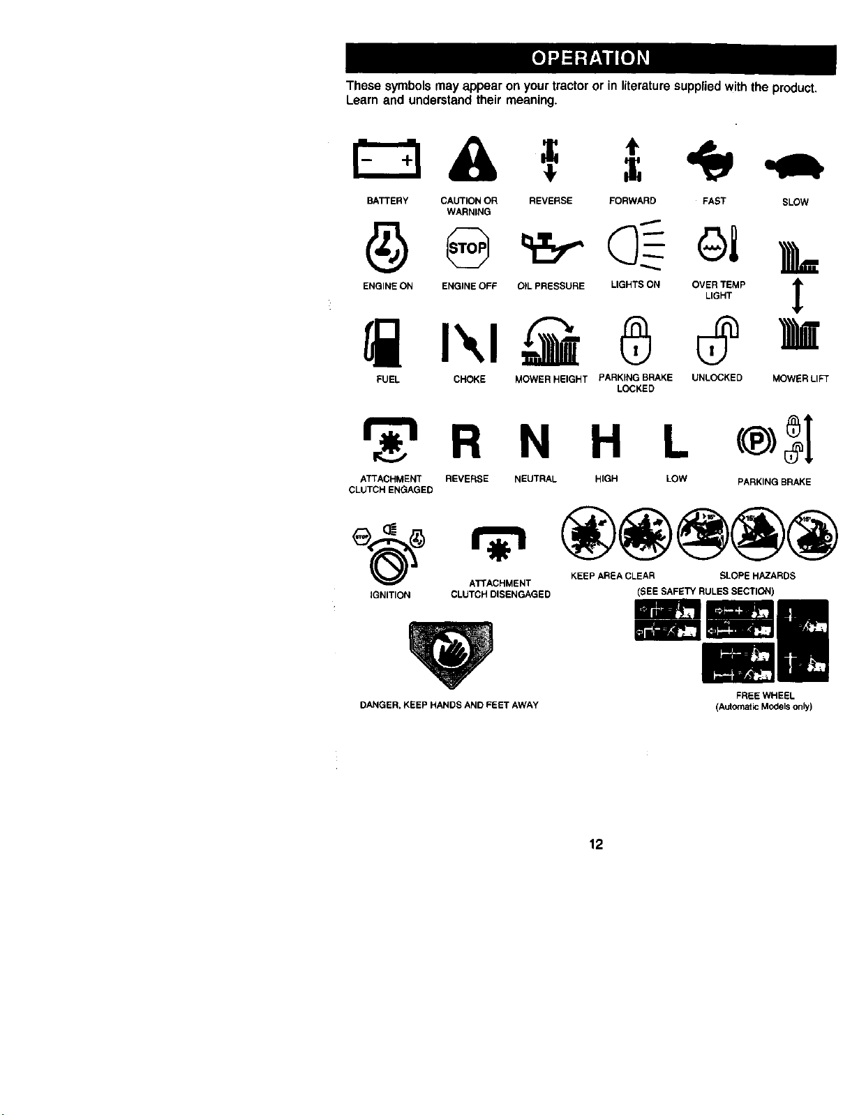
Thesesymbolsmayappearonyourtractororinliteraturesuppliedwiththe product,
Learnand understandtheirmeaning.
BATTERY CAUTION OR
WARNING
ENGINE ON ENGINE OFF
REVERSE FORWARD FAST SLOW
..=,...-
FUEL CHOKE
OIL PRESSURE LIGHTS ON OVER TEMP
LIGHT
MOWER HEIGHT PARKING BRAKE UNLOCKED MOWER LIFT
LOCKED
r 'l R N H L
ATTACHMENT REVERSE NEUTRAL HIGH LOW
CLUTCH ENGAGED
PARKING BRAKE
KEEP AREA CLEAR SLOPE HAZARDS
ATTACHMENT
IGNITION CLUTCH DISENGAGED (SEE SAFETY RULES SECTION)
DANGER, KEEPHANDSANDFEETAWAY
FREE WHEEL
(A_Omat_ Models on_)
12
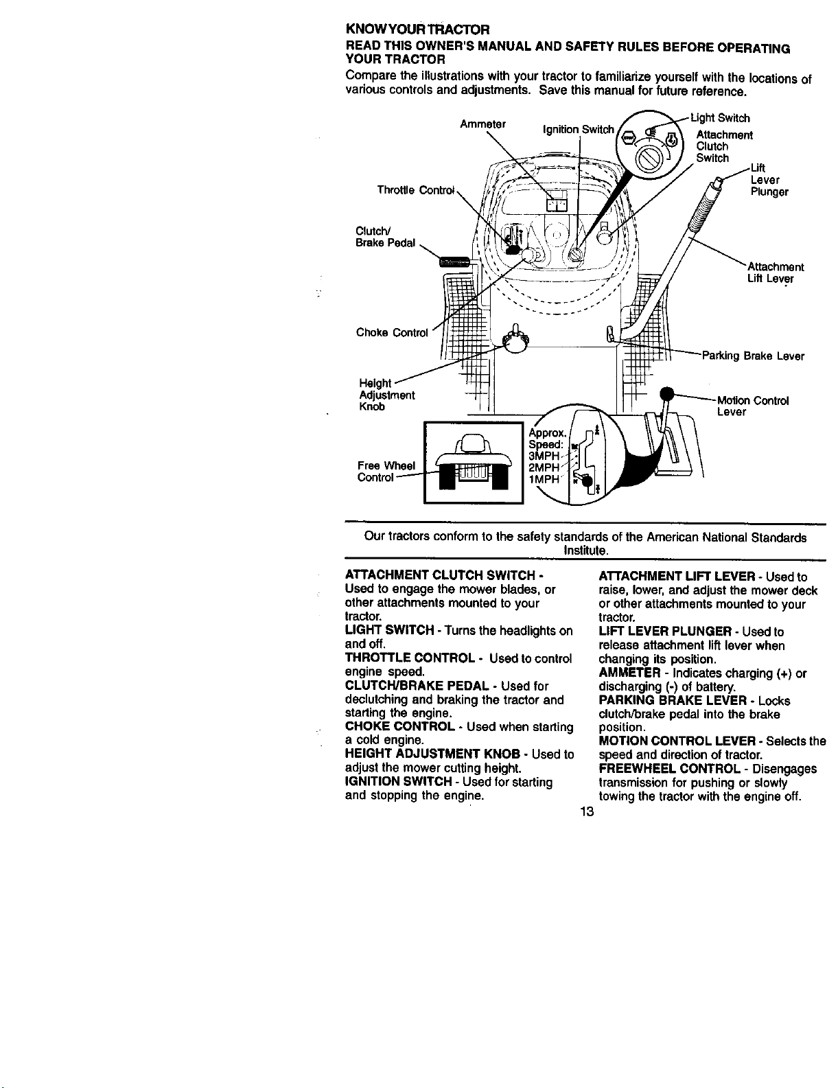
KNOWYOUR TRACTOR
READTHIS OWNER'S MANUAL AND SAFETY RULES BEFOREOPERATING
YOUR TRACTOR
Comparethe illustrationswithyourtractortofamiliarizeyourselfwiththe locationsof
variouscontrolsand adjustments.Save thismanualfor futurereference.
Amme_r
Ignition Switch
Attachment
Clutch
Switch
Lever
Throttle Plunger
Clutch/
Brake Pedal
Attachment
LiftLever
Choke Control/
Brake Lever
Adjustment
Knob
Lever
FreeWheel
Ourtractorsconformtothesafetystandardsofthe AmericanNationalStandards
Institute.
ATTACHMENT CLUTCH SWITCH -
Used to engage the mower blades, or
other attachments mounted to your
tractor.
LIGHT SWITCH - Turns the headlights on
and off.
THROTTLE CONTROL - Used to control
engine speed.
CLUTCH/BRAKE PEDAL - Used for
declutching and braking the tractor and
starting the engine.
CHOKE CONTROL - Used when starting
a cold engine.
HEIGHT ADJUSTMENT KNOB - Used to
adjust the mower cutting height.
IGNITION SWITCH - Used for starting
and stopping the engine.
ATTACHMENT LIFT LEVER - Used to
raise, lower, and adjust the mower deck
or other attachments mounted to your
tractor.
LIFT LEVER PLUNGER - Used to
release attachment lift lever when
changing its position.
AMMETER - Indicates charging (+) or
discharging (-) of battery.
PARKING BRAKE LEVER - Locks
clutch/brake pedal into the brake
position.
MOTION CONTROL LEVER - Selects the
speed and direction of tractor.
FREEWHEEL CONTROL - Disengages
transmission for pushing or slowly
towing the tractor with the engine off.
13
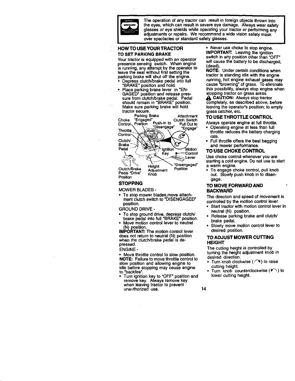
I_ he operation of any tractor can result in foreign objects thrown into I
the eyes, which can result in severe eye damage. Always wear safety
I
glasses or eye shields while operating your tractor or performing any
adjustments or repairs. We recommend a wide vision safety mask
over spectacles or standard safety glasses.
HOW TO USEYOUR TRACTOR
TO SET PARKING BRAKE
Your tractor is equipped with an operator
presence sensing switch. When engine
is running, any attempt by the operator to
leave the seat without first setting the
parking brake will shut off the engine.
• Depress clutch/brake pedal into full
"BRAKE" position and hold,
• Place parking brake lever in "EN-
GAGED position and release pres-
sure from clutch/brake pedal. Pedal
should remain in "BRAKE" position,
Make sure parking brake will hold
tractor secure.
ParkingBrake Attachment
Choke =Engaged" ClutchSwitch
Control,.Position Push-Into . PullOutto
\ \_Disengage "En,',a-,=
Throttle_X _..._ \- _._'_ uv
Control 5 y_
Brake_,_ _.._ _(_.7 .7
_o o _I_e_yy _._Lever
_I_. _Hei_ "Disengaged"
Clutch/Brake... Ad.='justment Position
Pedal Dnve Knob
PosiUon
STOPPING
MOWER BLADES-
• To stopmowerblades,moveattach-
mentclutchswitchto"DISENGAGED"
position.
GROUND DRIVE -
• To stopgrounddrive,depressclutch/
brake pedalintofull "BRAKE"position.
• Move motioncontrolleverto neutral
(N) posiUon.
IMPORTANT:The motioncontrollever
does not returnto neutral(N) position
when the clutch/brakepedalisde-
pressed.
ENGINE -
• Move throttlecontrolto slowposition.
NOTE: Failuretomovethrottlecontrolto
slow positionand allowingengine to
idlebefore stoppingmay cause engine
to"backfire'.
• Turnignitionkey to"OFF"positionand
removekey. Alwaysremovekey
when leavingtractorto prevent
unauthorizeduse.
• Never use choketo stopengine.
IMPORTANT: Leavingthe ignition
switchinany positionotherthan "OFF"
willcausethe batteryto bedischarged,
(dead).
NOTE; Under cedain conditionswhen
tractor is standing idle with the engine
running,hot engine exhaust gases may
cause "browning" of grass. To eliminate
this possibility, always stop engine when
stopping tractor on grass areas.
CAUTION: Always stop tractor
completely, as described above, before
leaving the operator's position; to empty
grass catcher, etc.
TO USE THROI-FLE CONTROL
Always operate engine at full throttle.
• Operating engine at less than full
throttle reduces the battery charging
rate.
• Full throttle offers the best bagging
and mower performance.
TO USE CHOKE CONTROL
Use choke control whenever you are
starting a cold engine. Do not use to start
a warm engine.
• To engage choke control, pull knob
out. Slowly push knob in to disen-
gage.
TO MOVE FORWARD AND
BACKWARD
The direction and speed of movement is
controlled by the motion control lever.
• Start tractor with motion control lever in
neutral (N) position.
• Release parking brake and clutch/
brake pedal.
• Slowly move motion control lever to
desired position.
TO ADJUST MOWER CUl-I'ING
HEIGHT
The cutting height is controlled by
turning the height adjustment knob in
desired direction.
• Turn knob clockwise (F_) to raise
cutting height.
• Turn knob counterclockwise (If_) to
lower cutting height.
14
The cutting height range is approxi-
mately 1-1/2" to 4". The heights are
measured from the ground to the blade
tip with the engine not running. These
heights are approximate and may vary
depending upon soil conditions, height
of grass and types of grass being
mowed.
• The average lawn should be cut to
approximately 2-1/2 inches during the
cool season and to over 3 inches
during hot months. For healthier and
better looking lawns, mow often and
after moderate growth.
• For best cutting performance, grass
over 6 inches in height should be
mowed twice. Make the first cut
relatively high; the second to desired
height.
TO ADJUST GAUGE WHEELS
Gauge wheels are properly adjusted
when they are slightly off the ground
when mower is at the desired cutting
height in operating position. Gauge
wheels then keep the deck in prober
position to help prevent scalping in most
terrain conditions.
• Adjust gauge wheels with tractor on a
flat level surface.
• Adjust mower to desired cutting height
(See "TO ADJUST MOWER CUTTING
HEIGHT" in the Operation section of
this manual).
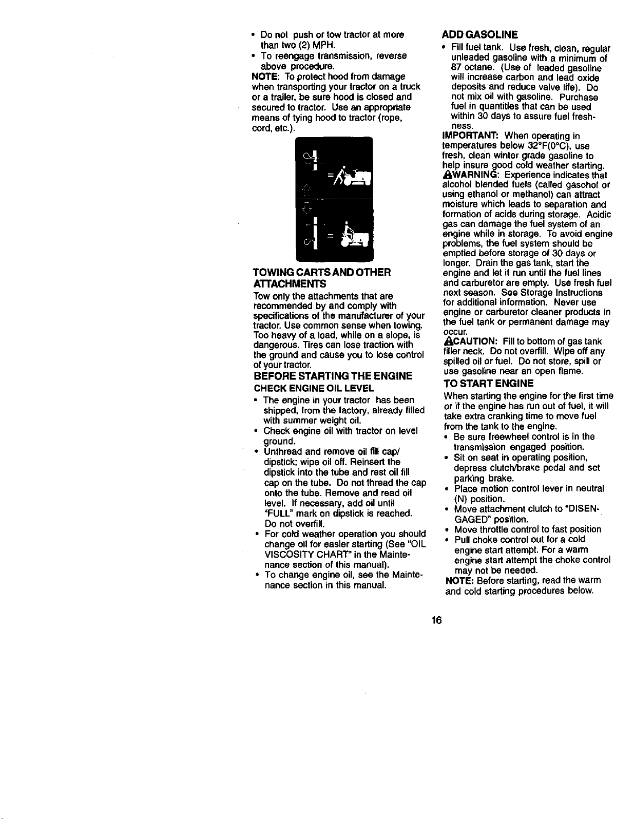
• With mower in desired height of cut
position, gauge wheels should be
assembled so they are slightly off the
ground. Install gauge wheel in
appropriate hole with shoulder bolt. 3/
8 washer, and 3/8-16 Iocknut and
tighten securely.
• Repeat for opposite side installing
gauge wheel in same adjustment hole.
3/8-16
Locknut \
Gauge
Wheel
Mounting
Bracke
Shoulder
Gaug
TO OPERATE MOWER
Yourtractorisequippedwithan operator
presencesensingswitch. Anyattemptby
theoperatortoleavethe seat withthe
engine runningand the attachment
clutchengaged willshut offtheengine.
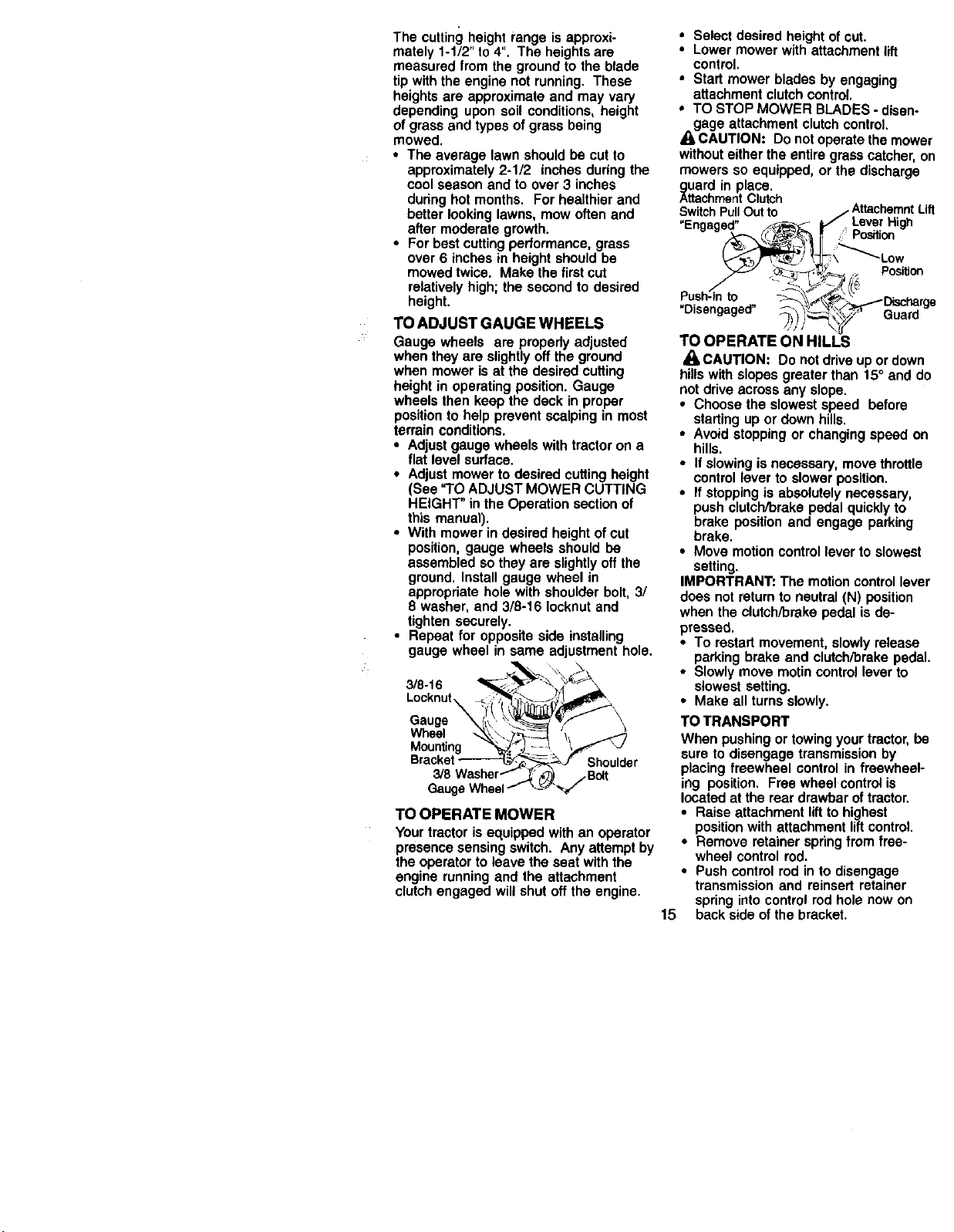
• Select desired height of cut.
• Lower mower with attachment lift
control,
• Start mower blades by engaging
attachment clutch control,
• TO STOP MOWER BLADES - disen-
gage attachment clutch control.
A CAUTION: Do not operate the mower
without either the entire grass catcher, on
mowers so equipped, or the discharge
_uard in place.
ttachmentClutch
SwitchPullOut to /, AttachemntLift
"Enaaaed" _,f_ _ Lever High
._ .'_',_, Position
Push-Into _-_,j_/_i_,_" _...Discharae
"Disengaged" _)_)_y---'_ Guard--
TO OPERATE ON HILLS
CAUTION: Do not drive up or down
hills with slopes greater than 15° and do
not drive across any slope.
• Choose the slowest speed before
starting up or down hills.
• Avoid stopping or changing speed on
hills.
• If slowing is necessary, move throttle
control lever to slower position.
• If stopping is absolutely necessary,
push clutch/brake pedal quickly to
brake position and engage parking
brake.
• Move motion control lever to slowest
setting.
IMPORTRANT: The motion control lever
does not return to neutral (N) position
when the clutch/brake pedal is de-
pressed.
• To restart movement, slowly release
parking brake and clutch/brake pedal.
• Slowly move motin control lever to
slowest setting.
• Make all turns slowly.
TO TRANSPORT
When pushing or towing your tractor, be
sure to disengage transmission by
placing freewheel control in freewheel-
ing position. Free wheel control is
located at the rear drawbar oftractor.
• Raise attachment liftto highest
position with attachment liftcontrol.
• Remove retainer spring from free-
wheel control rod.
• Push control rod in to disengage
transmission and reinsert retainer
spring into control rod hole now on
15 back side of the bracket.
• Do not pushor towtractorat more
thantwo(2) MPH.
• To reengagetransmission,reverse
above procedure.
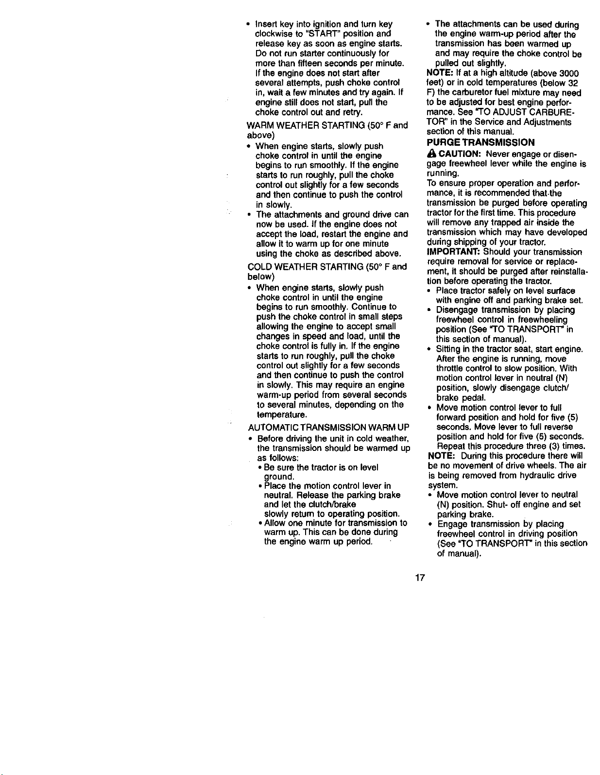
NOTE: Toprotecthoodfrom damage
when transportingyourtractorona truck
or a trailer,be sure hoodisclosedand
securedtotractor. Use anappropriate
meansoftyinghoodtotractor(rope,
cord,etc.).
r
TOWING CARTS AND OTHER
ATI'ACHMENTS
Tow only the attachments that are
recommended by and comply with
specifications of the manufacturer of your
tractor. Use common sense when towing.
Too heavy of a load, while on a slope, is
dangerous, Tires can lose traction with
the ground and cause you to lose control
of your tractor.
BEFORE STARTING THE ENGINE
CHECK ENGINE OIL LEVEL
• The engine in your tractor has been
shipped, from the factory, already filled
with summer weight oil.
• Check engine oil with tractor on level
ground.
• Unthread and remove oil fill cap/
dipstick; wipe oil off. Reinsert the
dipstick into the tube and rest oil fill
cap on the tube. Do not thread the cap
onto the tube. Remove and read oil
level. If necessary, add oil until
"FULL" mark on dipstick is reached.
Do not overfill.
• For cold weather operation you should
change oil for easier starting (See "OIL
VISCOSITY CHART" in the Mainte-
nance section of this manual).
• To change engine oil, see the Mainte-
nance section in this manual.
ADD GASOLINE
• Fill fuel tank. Use fresh, clean, regular
unleaded gasoline with a minimum of
87 octane. (Use of leaded gasoline
will increase carbon and lead oxide
deposits and reduce valve life). Do
not mix oil with gasoline. Purchase
fuel in quantities that can be used
within 30 days to assure fuel fresh-
ness.
IMPORTANT: When operating in
temperatures below 32°F(0°C), use
fresh, clean winter grade gasoline to
help insure good cold weather starting.
AWARNING: Experience indicates that
alcohol blended fuels (called gasohof or
using ethanol or methanol) can attract
moisture which leads to separation and
formation of acids during storage. Acidic
gas can damage the fuel system of an
engine while in storage. To avoid engine
problems, the fuel system should be
emptied before storage of 30 days or
longer. Drain the gas tank, start the
engine and let it run until the fuel lines
and carburetor are empty. Use fresh fuel
next season. Sea Storage Instructions
for additional information. Never use
engine or carburetor cleaner products in
the fuel tank or permanent damage may
occur.
_CAUTION: Fillto bottom ofgas tank
filler neck. Do not overfill. Wipe off any
spilled oil or fuel. Do not store, spill or
use gasoline near an open flame.
TO START ENGINE
When starting the engine for the first time
or if the engine has run out of fuel, it will
take extra cranking time to move fuel
from the tank to the engine.
• Be sure freewheel control is in the
transmission engaged position.
• Sit on seat in operating position,
depress clutch/brake pedal and set
parking brake.
• Place motion control lever in neutral
(N) position.
• Move attachment clutch to "DISEN-
GAGED" position.
• Move throttle control to fast position
• Pull choke control out for a cold
engine start attempt. For a warm
engine start attempt the choke control
may not be needed.
NOTE: Before starting, read the warm
and cold starting procedures below.
16
• Insertkeyintoignitionand turnkey
clockwise to "START"positionand
releasekey as soonas enginestarts.
Do not runstartercontinuouslyfor
more than fifteensecondsper minute.
Iftheenginedoesnot startafter
severalattempts,pushchokecontrol
in,waita few minutesandtryagain. If
enginestilldoes notstart,pullthe
choke controloutand retry.
WARM WEATHERSTARTING (50° Fand
above)
• When enginestarts,slowlypush
choke controlin untilthe engine
beginsto runsmoothly,Ifthe engine
startstorunroughly,pullthechoke
controloutslightlyfor a few seconds
and thencontinueto pushthe control
in slowly.
• The attachmentsand grounddrivecan
nowbe used.If theenginedoes not
acceptthe load,restartthe engineand
allowitto warmupfor one minute
usingthechokeas descdbedabove.
COLD WEATHERSTARTING(50° Fand
below)
• When enginestarts,slowlypush
chokecontrolin untiltheengine
beginsto runsmoothly.Continueto
pushthechokecontrolin smallsteps
allowingthe engineto acceptsmall
changesin speedand load,untilthe
chokecontrolisfully in, Iftheengine
startsto runroughly,pullthechoke
controloutslightlyfor a few seconds
andthen continuetopushthecontrol
in slowly.This may requirean engine
warm-upperiodfrom severalseconds
to severalminutes,dependingon the
temperature.
AUTOMATICTRANSMISSIONWARMUP
• Beforeddvingthe unitincoldweather,
the transmissionshouldbe warmed up
as follows:
• Be surethetractorison level
ground.
• Placethemotioncontrollever in
neutral.Releasethe parkingbrake
and let theclutch/breke
slowlyretum tooperatingposition.
•Allowone minutefor transmissionto
warmup.Thiscanbe doneduring
the enginewarm up period.
• The attachments can be used dudng
the engine warm-up period after the
transmission has been warmed up
and may require the choke control be
pulled out slightly.
NOTE: If at a high altitude (above 3000
feet) or in cold temperatures (below 32
F) the carburetor fuel mixture may need
to be adjusted for best engine perfor-
mance. See "TO ADJUST CARBURE-
TOR" in the Service and Adjustments
section of this manual.
PURGE TRANSMISSION
CAUTION: Never engage or disen-
gage freewheel lever while the engine is
running.
To ensure proper operation and perfor-
mance, it is recommended that.the
transmission be purged before operating
tractor for the firsttime. This procedure
will remove any trapped air inside the
transmission which may have developed
during shipping of your tractor.
IMPORTANT: Should your transmission
require removal for service or replace-
ment, it should be purged after reinstalla-
lion before operating the tractor.
• Place tractor safely on level surface
with engine off and parking brake set.
• Disengage transmission by placing
freewheel control in freewheeling
position (See "TO TRANSPORT" in
this section of manual).
• Sitting in the tractor seat, start engine.
After the engine is running, move
throttle control to slow position. With
motion control lever in neutral (N)
position, slowly disengage clutch/
brake pedal.
• Move motion control lever to full
forv_ard position and hold for five (5)
seconds. Move lever to full reverse
position and hold for five (5) seconds.
Repeat this procedure three (3) times.
NOTE: Dudng this procedure there will
be no movement of drive wheels. The air
is being removed from hydraulic drive
system.
• Move motion control lever to neutral
(N) position. Shut- off engine and set
parking brake.
• Engage transmission by placing
freewheel control in driving position
(See "TO TRANSPORT" in this section
of manual).
17
• Sittinginthetractor seat,startengine.
Afterthe engineis running,move
throttlecontroltohalf (t/2) speed.With
motioncontrollever in neutral(N)
position,slowlydisengageclutch/
brake pedal.
• Slowlymovemotioncontrollever
forward,afterthe tractormoves
approximatelyfive (5) feet, slowly
movemotioncontrollever toreverse
position.Afterthetractormoves
approximatelyfive (5) feet returnthe
motioncontrollever tothe neutral (N)
position.Repeat thisprocedurewith
themotioncontrollever three(3)
times.
• Yourtractoris nowpurgedand now
readyfor normaloperation.
MOWING TIPS
• Tirechainscannotbe usedwhen the
mowerhousingisattachedto tractor.
• Mower shouldbe properlyleveledfor
bestmowingperformance. See %0
LEVEL MOWER HOUSING"in the
Serviceand Adjustmentssectionof
this manual.
• The lefthandsideof mowershouldbe
usedfor trimming.
• Ddve so thatclippingsare discharged
ontothe area thathasbeen cut. Have
thecutareatothe rightofthe tractor.
Thiswillresultina moreevendistribu-
tionof clippingsand more uniform
cutting.
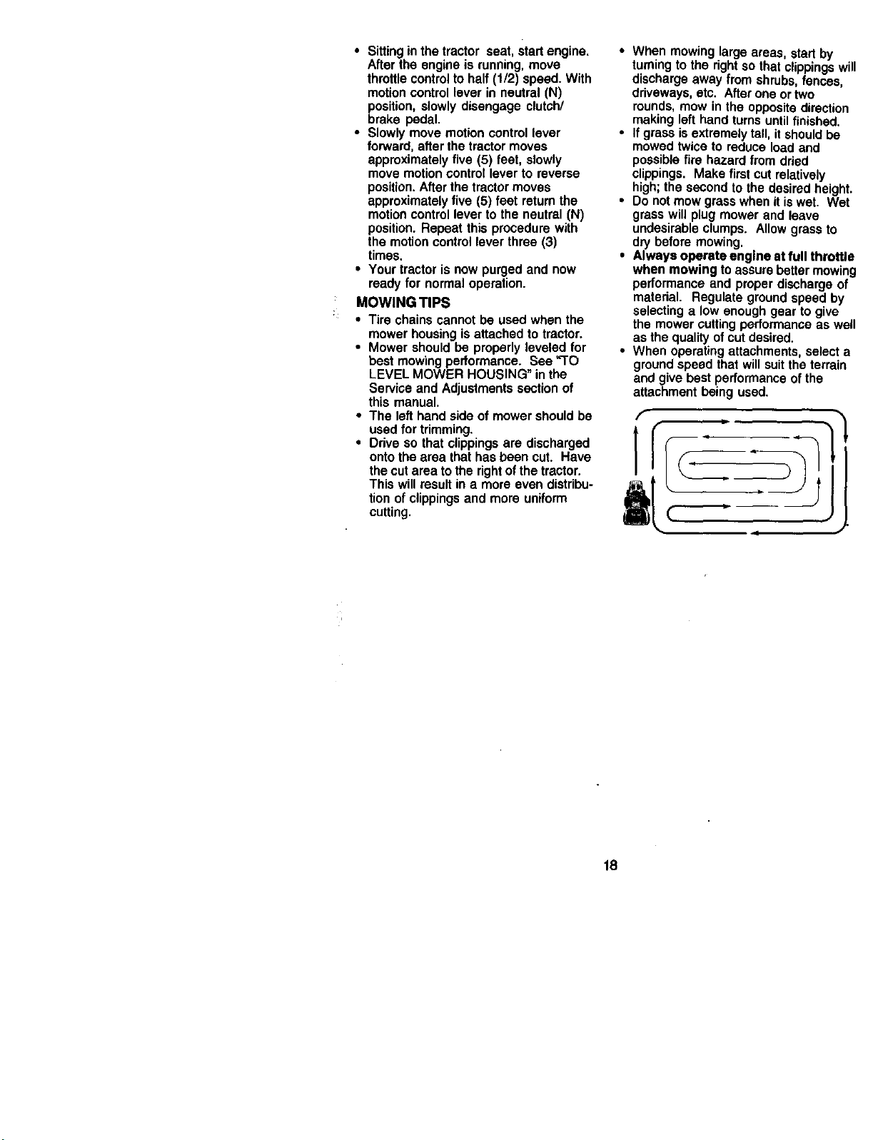
• When mowinglargeareas, startby
turningtothe rightsothatclippings
dischargeaway fromshrubs,fences
driveways, etc. Afterone ortwo
rounds,mow in the oppositedirectic
makinglefthandturnsuntilfinished.
• Ifgrassisextremelytall,it shouldbe
mowedtwiceto reduceloadand
possiblefire hazardfrom dried
clippings. Makefirst cutrelatively
high;thesecondto thedesiredheig
• Do notmow grasswhenit iswet, W
grasswillplugmowerand leave
undesirableclumps. Allowgrassto
dry beforemowing.
• Always operateengine at full throtl
when mowing toassurebettermowi
performanceand properdischargec
matedal. Regulategroundspeedb_
selectinga low enoughgear to give
the mowercuttingperformanceas w
asthe quality ofcutdesired.
• When operatingattachments,select
groundspeed thatwillsuittheterrai=
and givebestperformanceofthe
attachment being used.
f
18
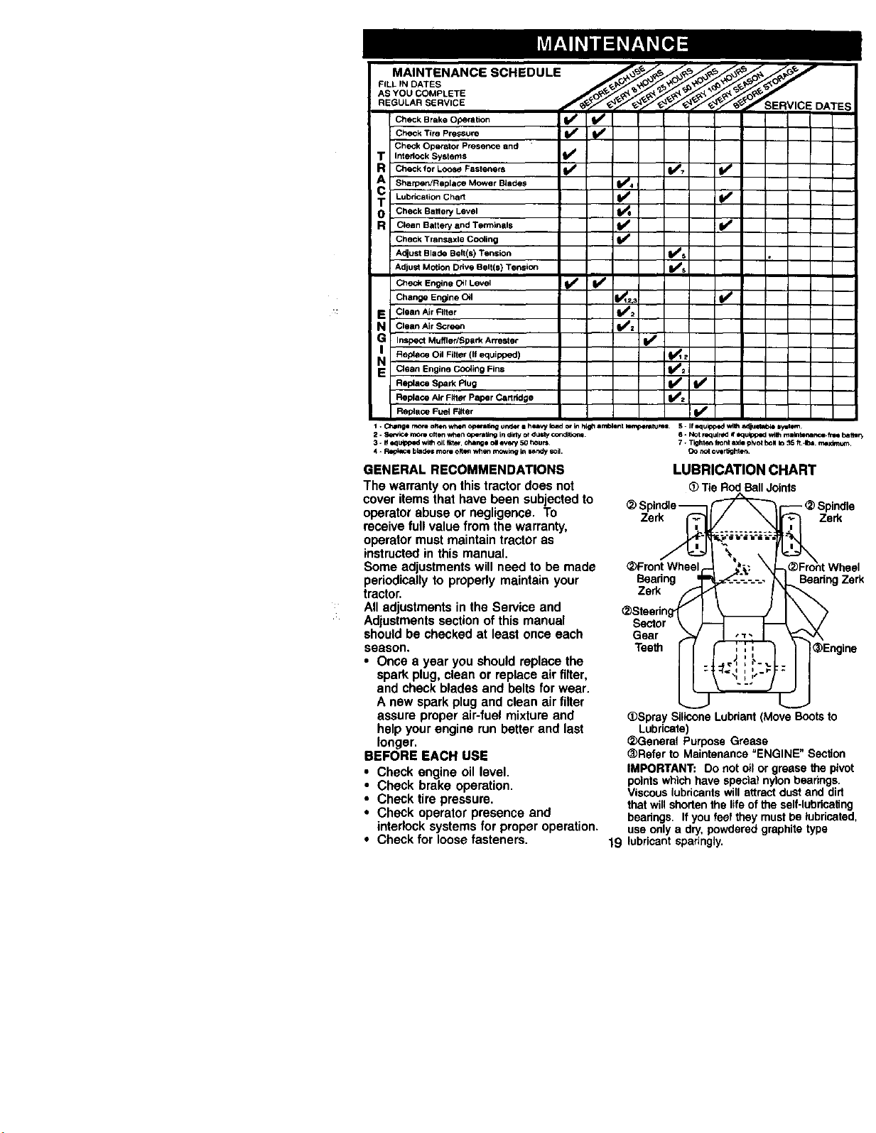
FILL IN DATES
Check Brake operation
Check Tire Pressure _
Check Operator PreSence and
T Interlock Systems
R Check for Loose Fasteners _ (l_;' IS*
Sharpen/ReplaOe Mower BJedes VB4
T Lubrication Chad I1_ lidd*
0 Check Battery Level
R Clean Battery and Terminals I_
Check Transaxle Co_ing
A_ust Blade Belt(s) Tension _s
Adju_ Motion Drive Belt(s) TensiOn ll_s
Check Engine Oil Level ! _ I_
Change Engine Olt I_q=,:
E Clean Air Filter _=
N CleanAirScreen _2
IG InSpect Muffler/Spark Arre_ter I_
Replace Oil Filter (if equipped) _ z
N Clean Engine Co_ing Fins Ibm=
Replace Spark Rug ll_
Replace Air Filter Paper Cartridge II_z
Replace Fue_ Filter I_
I . ChlPnge mo_ ofter_ whefl op,zml_l; _tldot ii healW load or bl hl,gfl anlDlenl _m| 5 - I f oquip_oe_ wl_l adju4tabie lytltem
2. S4m4ce more olten whet_ Qpera#n9 in dldy or dusty cor, dt6on_ S. NO t required if equlpped w_ malntena_.e.free batter_
3. If equipped wilh oil 1_4te_,chango oil ever_ 50 hours¸ 7 • Tighten fiont axle pivot boll to _5 ft -Ib=. maximum.
4 - R_lacl blades more Olttn when _k_ in w_ndy soil. CO not overtighte_.
GENERAL RECOMMENDATIONS
The warranty on this tractor does not
cover items that have been subjected to
operator abuse or negligence. To
receive full value from the warranty,
operator must maintain tractor as
instructed in this manual.
Some adjustments will need to be made
periodically to properly maintain your
tractor,
All adjustments in the Service and
Adjustments section of this manual
should be checked at least once each
season.
• Once a year you should replace the
spark plug, clean or replace air filter,
and check blades and belts for wear.
A new spark plug and clean air filter
assure proper air-fuel mixture and
help your engine run better and last
longer.
BEFORE EACH USE
• Check engine oil level.
• Check brake operation.
• Check tire pressure.
• Check operator presence and
interlock systems for proper operation,
• Check for loose fasteners.
LUBRICATION CHART
(_ Tie Rod Ball Joints
_) Spindle _ _ _ _) Spindle
_)Front Wheel_ _ X_)Fro_t Wheel
Beadng =_.c._-..-_____, _,,I Bearing Zsrk
_Steering_ I _- IX >
Sector \ _ _-_ __/
Gear F_/ _ _---_'/X
Teeth _ _Engine
•Spray Silicone Lubriant (Move Boots to
Lubricate)
_Generat Purpose Grease
<_Rsferto Maintenance=ENGINE"Section
IMPORTANT: Donot oil or greasethe pivot
pointswhichhave specla_nylonbearings.
Viscous lubricants will attract dust and dirt
that will shorten the life of the self-lubricating
bearings. If you feel they must be lubricated,
use only a dry, powdered graphite type
19 lubricant sparingly.
TRACTOR
Always observe safety rules when
performing any maintenance.
BRAKE OPERATION
If tractor requires more than six (6) feet
stopping distance at high speed in
highest gear, then brake must be
adjusted. (See =TO ADJUST BRAKE" in
the Service and Adjustments section of
this manual).
TIRES
• Maintain proper air pressure in all tires
(See "PRODUCT SPECIFICATIONS"
section of this manual).
• Keep tires free of gasoline, oil, or
insect control chemicals which can
harm rubber,
• Avoid stumps, stones, deep ruts, sharp
objects and other hazards that may
cause tire damage.
NOTE; To seal tire punctures and
prevent flat tires due to slow leaks, tire
sealant may be purchased from your
local parts dealer. Tire sealant also
prevents tire dry rot and corrosion.
OPERATOR PRESENCE SYSTEM
Be sure operator presence and interlock
systems are working properly. If your
tractor does not function as described,
repair the problem immediately.
• The engine should not start unless the
clutch/brake pedal is fully depressed
and attachement clutch control is in
the disengaged position.
• When the engine is running, any
attempt by the operator to leave the
seat without first setting the parking
brake should shut off the engine.
• When the engine is running and the
attachment clutch is engaged, any
attempt by the operator to leave the
seat should shut off the engine.
• The attachment clutch should never
operate unless the operator is in the
seat,
BLADE CARE
For best results mower blades must be
kept sharp. Replace bent or damaged
blades.
BLADE REMOVAL
• Raise mower to highest position to
allow access to blades.
• Remove hex bolt, lock washer and flat
washer securing blade.
• Install new or resharpened blade with
trailing edge up towards deck as
shown
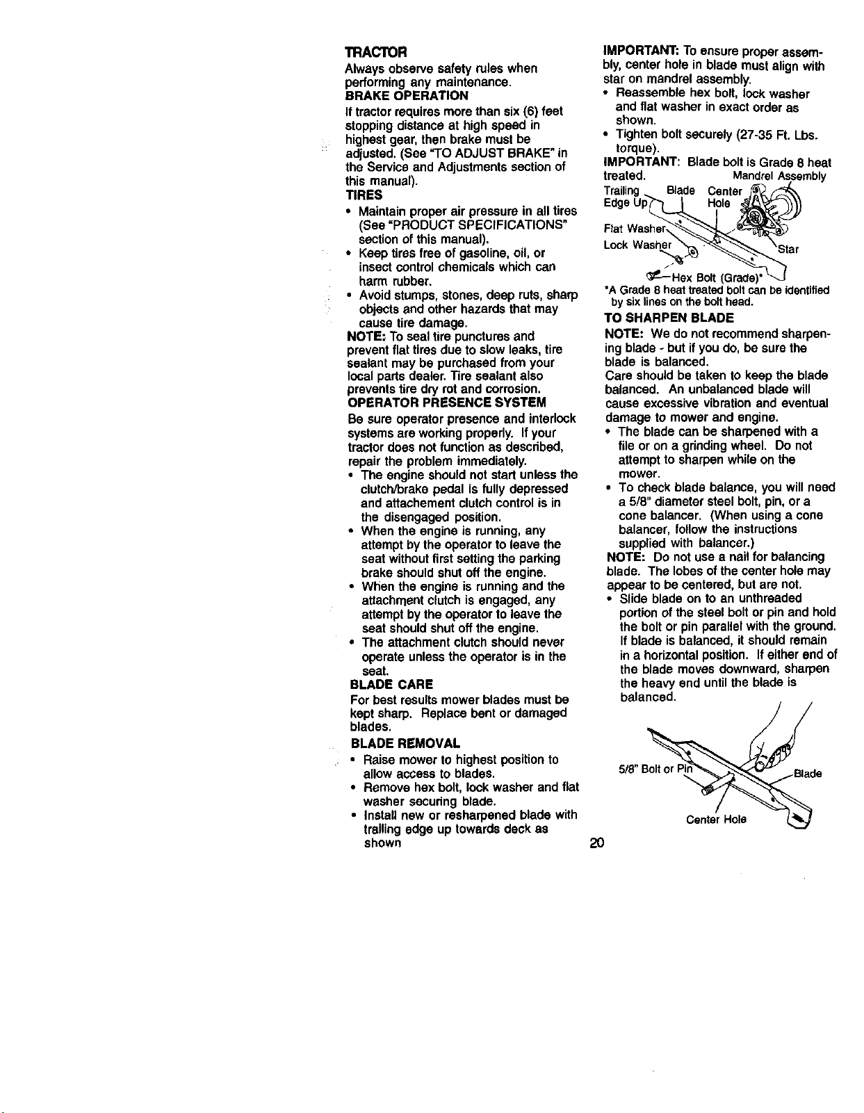
IMPORTANT: To ensure proper assem-
bly, center hole in blade must align with
star on mandrel assembly.
• Reassemble hex bolt, lock washer
and flat washer in exact order as
shown.
• Tighten bolt securely (27-35 R. Lbs.
torque).
IMPORTANT: Blade bolt is Grade 8 heat
treated. MandrelAssembly
Blade Center
Hole
Lock
_P-'--Hex Bolt (Grade)'
*A Grade 8 heattreatedboltcanbe identified
by sixlinesonthe bolthead.
TO SHARPEN BLADE
NOTE: We do not recommend sharpen-
ing blade - but if you do, be sure the
blade is balanced.
Care should be taken to keep the blade
balanced. An unbalanced blade will
cause excessive vibration and eventual
damage to mower and engine.
• The blade can be sharpened with a
file or on a grinding wheel. Do not
attempt to sharpen while on the
mower.
• To check blade balance, you will need
a 5/8" diameter steel bolt, pin, or a
cone balancer. (When using a cone
balancer, follow the instructions
supplied with balancer.)
NOTE: Do not use a nail for balancing
blade. The lobes of the center hole may
appear to be centered, but are not.
• Slide blade on to an unthraaded
portion of the steel bolt or pin and hold
the bolt or pin parallel with the ground.
If blade is balanced, it should remain
in a horizontal position. If either end of
the blade moves downward, sharpen
the heavy end until the blade is
balanced.
5/8"B_d e
Center Hole
2O
BATI'ERY
Your tractor has a battery charging
system which is sufficient for normal use.
However, periodic charging of the battery
with an automotive charger will extend
its life.
• Keep battery and terminals clean.
• Keep battery bolts tight.
• Keep small vent holes open.
• Recharge at 6-10 amperes for 1 hour.
NOTE: The original equipment battery on
your tractor is maintenance free. Do not
attempt to open or remove caps or
covers. Adding or checking level of
electrolyte is not necessary.
TO CLEAN BATTERY AND TERMINALS
Corrosion and dirt on the battery and
terminals can cause the battery to "leak"
power.
• Remove terminal guard.
• Disconnect BLACK battery cable first
then RED battery cable and remove
battery from tractor.
• Rinse the battery with plain water and
dry.
• Clean terminals and battery cable
ends with wire brush until bright.
• Coat terminals with grease or petro-
leum jelly.
• Reinstall battery (See "REPLACING
BATTERY" in the SERVICE AND
ADJUSTMENTS section of this
manual).
V-BELTS
Check V-belts for deterioration and wear
after 100 hours of operation and replace
if necessary. The belts are not adjustable.
Replace belts if they begin to slip from
wear.
TRANSAXLE COOLING
The transmission fan and cooling fins
should be kept clean to assure proper
cooling.
Do not attempt to clean fan or transmis-
sion while engine is running or while the
transmission is hot. To prevent possible
damage to seals, do not use high
pressure water or steam to clean
transaxle.
• Inspect cooling fan to be sure fan
blades are intact and clean.
• Inspect cooling fins for dirt, grass
clippings and other materials. To
prevent damage to seals, do not use
compressed air or high pressure
sprayer to clean cooling fins.
TRANSAXLE PUMP FLUID
The transaxle was sealed at the factory
and fluid maintenance is not required for
the life of the transaxle. Should the
transaxle ever leak or require servicing,
contact your nearest authorized service
center/department.
ENGINE
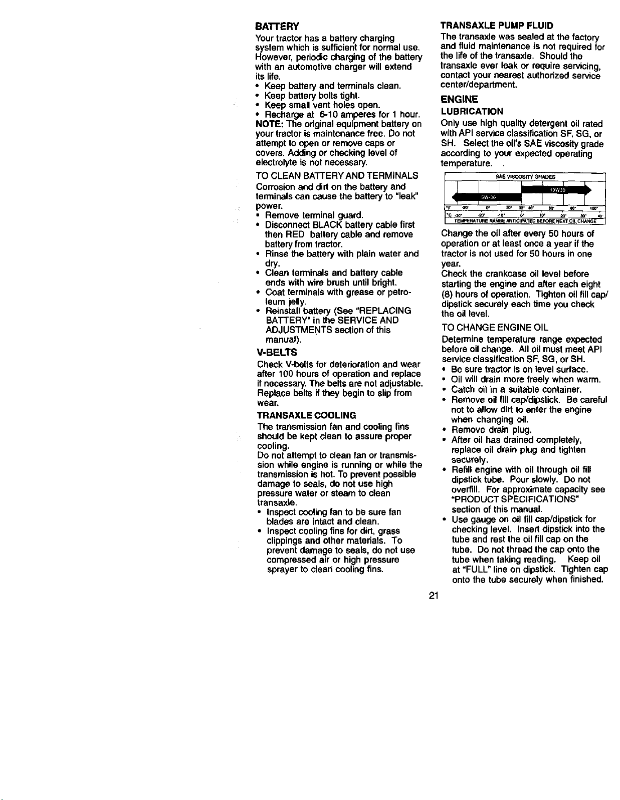
LUBRICATION
Only use high quality detergent oil rated
with API service classification SF, SG, or
SH. Select the oil's SAE viscosity grade
according to your expected operating
temperature.
SAE VISCOSI'W GRADES
Change the oil after every 50 hours of
operation or at least once a year ifthe
tractor is not used for 50 hours in one
year.
Check the crankcase oil level before
starting the engine and after each eight
(8) hours of operation. Tighten oil fill cap/
dipstick securely each time you check
the oil level.
TO CHANGE ENGINE OIL
Determine temperature range expected
before oil change. All oil must meet API
service classification SF, SG, or SH.
• Be sure tractor is on level surface.
• Oil will drain more freely when warm.
• Catch oil in a suitable container.
• Remove oil fill cap/dipstick. Be careful
not to allow dirt to enter the engine
when changing oil.
• Remove drain plug.
• After oil has drained completely,
replace oil drain plug and tighten
securely.
• Refill engine with oil through oil fill
dipstick tube. Pour slowly. Do not
overfill. For approximate capacity see
"PRODUCT SPECIFICATIONS"
section of this manual.
• Use gauge on oil fillcap/dipstick for
checking level. Insert dipstick into the
tube and rest the oil fill cap on the
tube. Do not thread the cap onto the
tube when taking reading. Keep oil
at "FULL" line on dipstick. Tighten cap
onto the tube securely when finished.
21
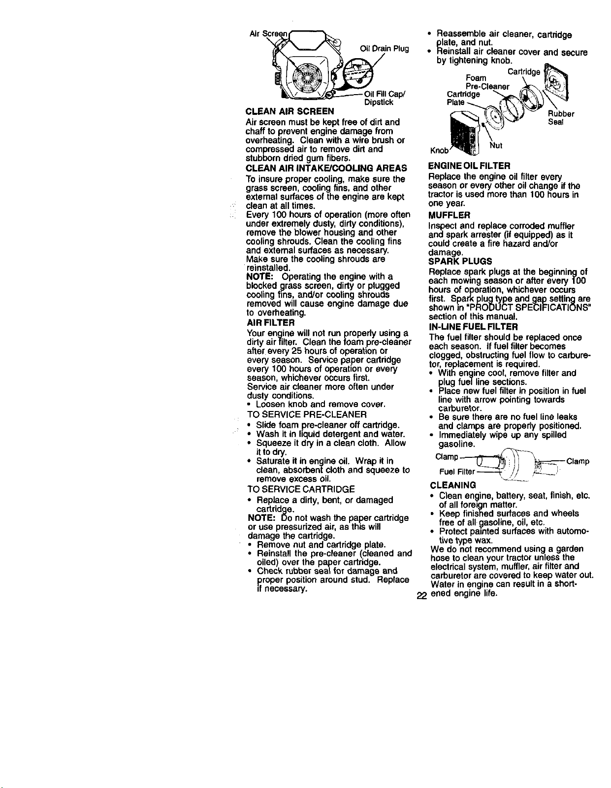
Air S__in Plug
_Oil FillCap/
Dipstick
CLEAN AIR SCREEN
Air screen must be kept free of dirt and
chaff to prevent engine damage from
overheating. Clean with a wire brush or
compressed air to remove dirt and
stubborn dried gum fibers.
CLEAN AIR INTAKE/COOLING AREAS
To insure proper cooling, make sure the
grass screen, cooling fins, and other
external surfaces of the engine are kept
clean at airtimes.
_: Every 100 hours of operation (more often
under extremely dusty, dirty conditions),
remove the blower housing and other
cooling shrouds. Clean the cooling fins
and external surfaces as necessary.
Make sure the cooling shrouds are
_reinstalled.
NOTE: Operating the engine with a
blocked grass screen, dirty or p_uggod
cooling fins, and/or cooling shrouds
removed will cause engine damage due
to overheating.
AIR FILTER
Your engine will not run properly using a
dirty airfilter. Clean the foam pre-cleaner
after every 25 hours of operation or
every season. Service paper cartridge
every 100 hours of operation or every
season, whichever occurs first.
Service air cleaner more often under
dusty conditions.
• Loosen knob and remove cover.
TO SERVICE PRE-CLEANER
Slide foam pre-cleaner off cartridge.
Wash it in hquid detergent and water.
Squeeze it dry in a clean cloth. Allow
it to dry.
• Saturate it in engine oil. Wrap it in
clean, absorbent cloth and squeeze to
remove excess oil.
TO SERVICE CARTRIDGE
• Replace a dirty, bent, or damaged
cartridge.
NOTE: Do not wash the paper cartridge
or use pressurized air, as this will
damage the cartridge.
• Remove nut and cartridge plate.
• Reinstall the pre-cleaner (cleaned and
oiled) over the paper cartridge.
• Check rubber seal for damage and
p.roperposition around stud. Replace
_fnecessary.
• Reassemble air cleaner, cartddge
plate, and nut.
• Reinstall air cleaner cover and sscur
by tightening knob.
Cartridge
Foam
Cadddge
Rubber
Seal
Nut
ENGINE OIL FILTER
Replace the engine oil filter every
season or every other oil change if the
tractor is used more than 100 hours in
one year,
MUFFLER
Inspect and replace corroded muffler
and spark arrester (if equipped) as it
could create a fire hazard and/or
damage,
SPARK PLUGS
Replace spark plugs at the beginning Q
each mowing season or after every 10(
hours of operation, whichever occurs
first. Spark plugtype and gap setting a_
shown in "PRODUCT SPECIFICATION',
section of this manual.
IN-LINE FUEL FILTER
The fuel filter should be replaced once
each season. If fuel filter becomes
clogged obstructing fuel flow to cerbur
tor, replacement is required.
• With engine cool, remove filter and
plug fuel line sections.
• Place new fuel filter in position in fue
line with arrow pointing towards
carburetor.
• Be sure there are no fuel line leaks
and clamps are properly positioned.
• Immediately wipe up any spilled
gasoline.
Foe,F"tor V2__
CLEANING
i lean engine, battery, seat, finish, e
of all foreign matter.
Keep finished surfaces and wheels
free of all gasoline, oil, etc.
Protect pemted surfaces with autom_
tire type wax.
We do not recommend using a garden
hose to clean your tractor unless the
electrical system, muffler, air filter and
carburetor are covered to keep water o
Water in engine can result in a short-
22 ened engine life.
_CAUTION: Before performing any service or adjustments:
• Depress clutch/brake pedal fully and set parking brake.
• Place motion control lever in neutral (N) position.
• Place attachment clutch in "DISENGAGED" position.
• Turn ignition key "OFF" and remove key.
• Make sure the blades and all moving parts have completely stopped.
• Disconnect spark plug wire from spark plug and place wire where it cannot
come in contact with plug.
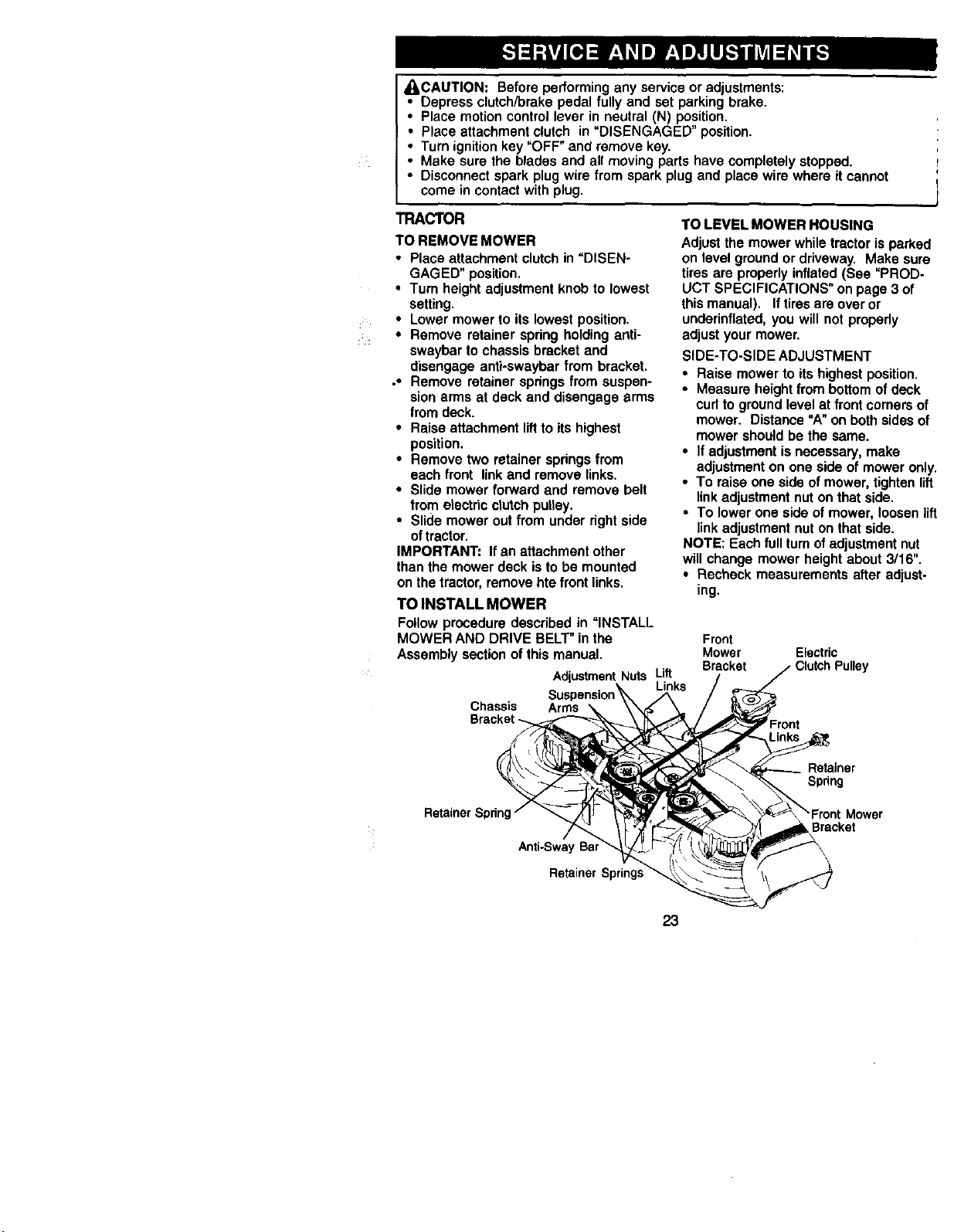
TRACTOR
TO REMOVE MOWER
• Place attachment clutch in "DISEN-
GAGED" position.
• Turn height adjustment knob to lowest
setting.
• Lower mower to its lowest position.
• Remove retainer spring holding anti-
swaybar to chassis bracket and
disengage anti-swaybar from bracket.
,* Remove retainer springs from suspen-
sion arms at deck and disengage arms
from deck.
• Raise attachment lift to its highest
position.
• Remove two retainer springs from
each front link and remove links.
• Slide mower forward and remove belt
from etectric crutchputtey.
• Slide mower out from under right side
oftractor.
IMPORTANT: If an attachment other
than the mower deck is to be mounted
on the tractor, remove hie front links.
TO INSTALL MOWER
Follow procedure described in "INSTALL
MOWER AND DRIVE BELT" in the
Assembly section of this manual.
AdiustmentNuts Lift
Links
Chassis Arms
Bracket _.
TO LEVEL MOWER HOUSING
Adjust the mower while tractor is parked
on level ground or driveway. Make sure
tires are properly inflated (See =PROD-
UCT SPECIFICATIONS" on page 3 of
this manual). If tires are over or
underinflated, you will not properly
adjust your mower.
SIDE-TO-SIDE ADJUSTMENT
• Raise mower to its highest position.
• Measure height from bottom of deck
curl to ground level at front corners of
mower. Distance "A" on both sides of
mower should be the same.
• If adjustment is necessary, make
adjustment on one side of mower only.
• To raise one side of mower, tighten lift
linkadjustment nut on that side.
• To lower one side of mower, loosen lift
link adjustment nut on that side.
NOTE: Each full turn of adjustment nut
will change mower height about 3/16".
• Recheck measurements after adjust-
ing.
Front
Mower Electric
Bracket
RetainerSpring/
Anti-SwayBa=
Retainer Spring_
Retainer
Spring
Mower
23
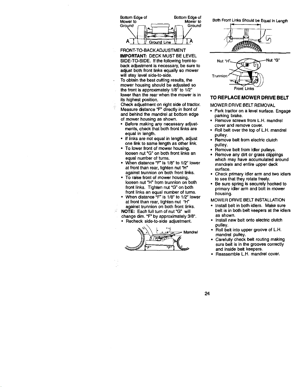
BottomEdgeof BottomEdgeof
Mower to Mowerto
Ground _ [_ _ Ground
FRONT-TO-BACK ADJUSTMENT
IMPORTANT: DECK MUST BE LEVEL
SIDE-TO-SIDE, If the following front-to-
back adjustment is necessary, be sure to
adjust both front links equally so mower
will stay level side-to-side.
To obtain the best cutting results, the
mower housing should be adjusted so
the front is approximately 1/8" to 1/2"
lower than the rear when the mower is in
its highest position.
Check adjustment on right side of tractor.
Measure distance "F" directly in front of
and behind the mandrel at bottom edge
of mower housing as shown.
• Before making any necessary adjust-
ments, check that both front links are
equal in length.
• If links are not equal in length, adjust
one link to same length as other link.
• To lower front of mower housing,
loosen nut "G" on both front links an
equal number of turns.
• When distance "F" is 1/8" to 1/2" lower
at front than rear, tighten nut "H"
against trunnion on both front links.
• To raise front of mower housing,
loosen nut "H" from trunnion on both
front links. Tighten nut "G" on bath
front links an equal number of turns.
• When distance "F" is 1/8" to 1/2" lower
at front than roar, tighten nut "H"
against trunnion on both front links.
NOTE: Each full turn of nut "G" will
change dim. "F" by approximately 3/8".
• Recheck side-to-side adjustment.
=_o " o o°° Mandrel
BothFrontLinksShouldbe EqualinLength
Nut "H__S" Nut "G"
Trunnion "__
Front Links
TO REPLACE MOWER DRIVE BELT
MOWER DRIVE BELT REMOVAL
• Park tractor on a level surface. Engage
parking brake.
• Remove screws from L.H. mandrel
cover and remove cover.
• Roll belt over the top of L.H. mandrel
pulley.
• Remove belt from electric clutch
pulley.
• Remove belt from idler pulleys.
• Remove any dirt or grass clippings
which may have accumulated around
mandrels and entire upper deck
surface.
• Check pdmary idler arm and two idlers
to see that they rotate freely.
• Be sure spring is securely hooked to
primary idler arm and bolt in mower
housing.
MOWER DRIVE BELT INSTALLATION
• Install belt in both idlers. Make sure
belt is in both belt keepers at the idlers
as shown.
• Install new belt onto electric clutch
pulley.
• Roll belt into upper groove of L.H.
mandrel pulley.
• Carefully check belt routing making
sure belt is in the grooves correctly
and inside belt keepers.
• Reassemble L.H. mandrel cover.
24
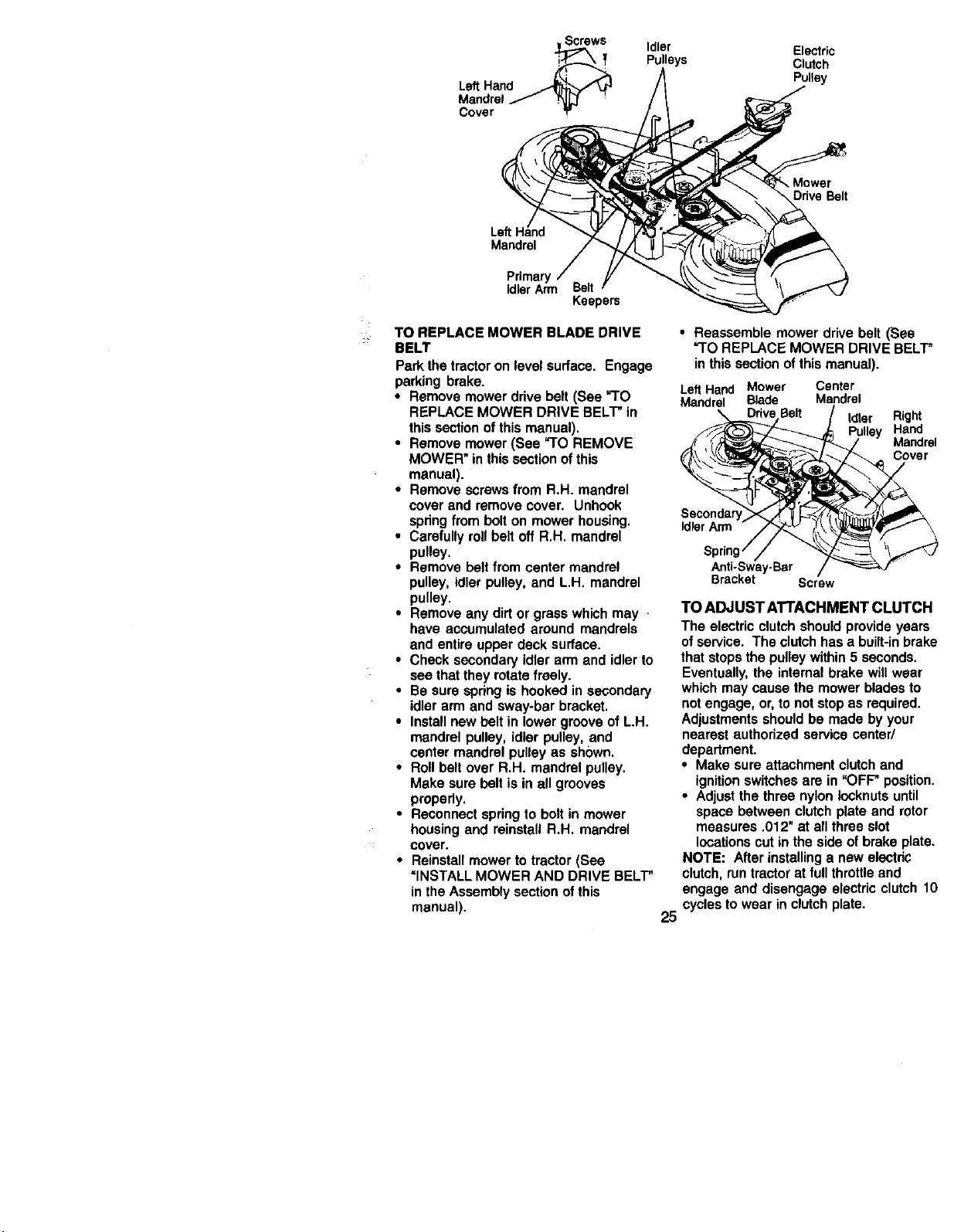
Screws Idler Electric
Pulleys Clutch
Pulley
LeftHand
Cover
Left
Mandrel
Pdmaw
IdlerArm
Keepem
TO REPLACE MOWER BLADE DRIVE
BELT
Park the tractor on level surface. Engage
parking brake,
• Remove mower drive belt (See "TO
REPLACE MOWER DRIVE BELT" in
this section of this manual),
• Remove mower (See "TO REMOVE
MOWER" in this section ofthis
manual).
• Remove screws from R.H. mandrel
cover and remove cover. Unhook
spring from bolt on mower housing,
• Carefully roll belt off R.H. mandrel
pulley.
• Remove belt from center mandrel
pulley, idler pulley, and L,H. mandrel
pulley,
• Remove any dirt or grass which may
have accumulated around mandrels
and entire upper deck surface.
• Check secondary idler arm and idler to
see that they rotate freely.
• Be sure spring is hooked in secondary
idler arm and sway-bar bracket,
• Install new belt in lower groove of L.H.
mandrel pulley, idler pulley, and
center mandrel pulley as shown.
• Roll belt over R.H. mandrel pulley.
Make sure belt is in all grooves
properly.
• Reconnect spring to bolt in mower
housing and reinstall R.H. mandrel
cover.
• Reinstall mower to tractor (See
"INSTALL MOWER AND DRIVE BELT"
in the Assembly section of this
manual).
Ddve Belt
• Reassemble mower drive belt (See
=TO REPLACE MOWER DRIVE BELT"
in this section of this manual).
LeftHand Mower Center
Mandrel Blade Mandrel
Idler Right
Hand
Mandrel
Cover
Idler Arm
Anti-Sway-Bar
Bracket Screw
TO ADJUST A'I'rACHMENT CLUTCH
The electric clutch should provide years
of service. The clutch has a built-in brake
that stops the pulley within 5 seconds.
Eventually, the internal brake will wear
which may cause the mower blades to
not engage, or, to not stop as required.
Adjustments should be made by your
nearest authorized service center/
department.
• Make sure attachment clutch and
ignition switches are in "OFF" position.
• Adjust the three nylon Iocknuts until
space between clutch plate and rotor
measures .012" at all three slot
locations cut in the side of brake plate.
NOTE: After installing a new electdc
clutch, run tractor at full throttle and
engage and disengage electric clutch 10
25 cycles to wear in clutch plate.
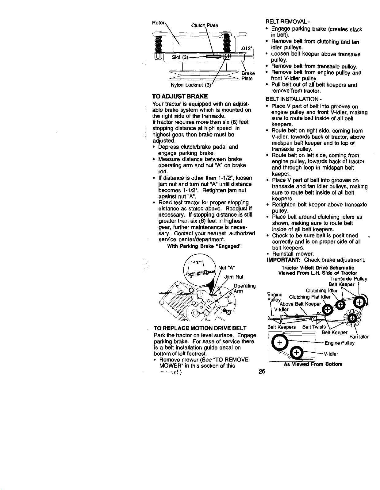
Rotor Clutch Plate
Slot
<
Nylon Locknut (31
TO ADJUST BRAKE
Yourtractorisequippedwithan adjust-
able brakesystemwhichis mountedon
therightsideofthetransaxle.
Iftractorrequiresmorethansix(6) feet
stoppingdistanceat highspeed in
highestgear,thenbrake mustbe
adjusted.
• Depressclutch/brakepedaland
engage parkingbrake.
• Measuredistancebetween brake
operatingarm and nut=A"on brake
rod.
• If distanceisotherthan 1-1/2",loosen
jam nutand turnnut=A"untildistance
becomes1-1/2". Retightenjam nut
againstnut"A".
• Roadtest tractorfor properstopping
distanceas statedabove. Readjustif
necessary, if stoppingdistanceis still
greaterthan six(6) feet in highest
gear,further maintenanceis neces-
sary. Contactyournearest authorized
service center/department.
With Parking Brake "Engaged"
,_ Nut =A"
__OrPme rating
TO REPLACE MOTION DRIVE BELT
Park the tractor on level surface. Engage
parking brake. For ease of service there
is a belt installation guide decal on
bottom of left footrest.
• Remove mower (See "TO REMOVE
MOWER" in this section of this
BELTREMOVAL-
• Engageparkingbrake(createsslack
inbelt).
• Removebeltfrom clutchingandfan
idler pulleys.
• Loosenpelt keeper above transaxle
pulley.
• Removebelt from transaxlepulley.
• Removebelt from enginepulleyand
front V-idler pulley.
• Pullbeltoutofall belt keepersand
removefrom tractor.
BELT INSTALLATION -
• Place V part of pelt intogrooves on
engine pulley and front V-idler, making
sure to route belt inside of all belt
keepers.
• Route belt on right side, coming from
V-idler, towards back of tractor, above
midspan belt keeper and to top of
transaxle pulley.
• Route belt on left side, coming from
engine pulley, towards back of tractor
and through loop in midspan belt
keeper.
• Place V part of belt into grooves on
transaxle and fan idler pulleys, making
sure to route belt inside of all belt
keepers.
• Retighten belt keeper above transaxle
pulley.
• Place belt around clutching idlers as
shown, making sure to route belt
inside of all belt keepers.
• Check to be sure belt is positioned
correctly and is on proper side of all
belt keepers.
• Reinstall mower.
IMPORTANT: Check brake adjustment.
Tractor V-Belt Drive Schematic
Viewed From L,H. Side of Tractor
Transaxle Pulley
V-Idler
26
Belt Keepers Belt Twists
I Belt Keeper
Fa idler
_ Engine Pulley
_111_i_ v'ldler
AS Viewed From Bottom
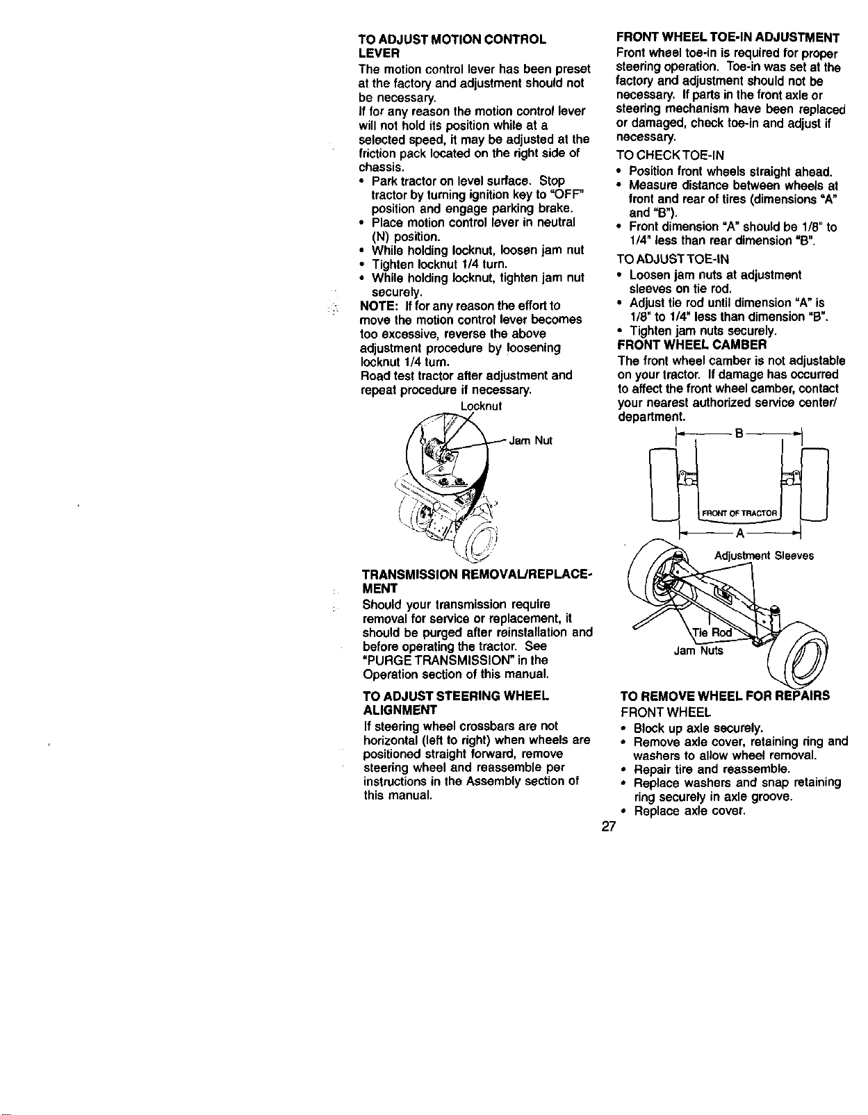
TO ADJUST MOTION CONTROL
LEVER
The motion control lever has boon preset
at the factory and adjustment should not
be necessary.
If for any reason the motion control lever
will not hold its position while at a
selected speed, it may be adjusted at the
friction pack located on the right side of
chassis.
• Park tractor on level surface. Stop
tractor by turning ignition key to "OFF"
position and engage parking brake.
• Place motion control lever in neutral
(N) position.
• While holding Iocknut, loosen jam nut
• Tighten Iocknut 1/4 turn.
• While holding Iocknut, tighten jam nut
securely.
NOTE: If for any reason the effort to
move the motion control lever becomes
too excessive, reverse the above
adjustment procedure by loosening
lecknut 1/4 turn.
Road test tractor after adjustment and
repeat procedure if necessary.
Locknut
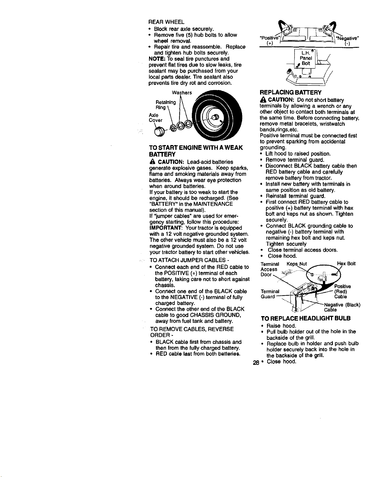
FRONT WHEELTOE-IN ADJUSTMENT
Frontwheeltoe-inis requiredfor proper
steedngoperation.Toe-inwas setat the
factory and adjustmentshouldnotbe
necessary.Ifpartsinthefront axleor
steeringmechanismhave been replaced
or damaged,checktoe-inand adjustif
necessary.
TOCHECKTOE-IN
• Positionfrontwheelsstraightahead,
• Measuredistancebetweenwheelsat
frontand rearoftires(dimensions=A"
and "B").
• Frontdimension"A"shouldbe 1/8"to
1/4"lessthan rear dimension"B".
TO ADJUST TOE-IN
• Loosen jam nuts at adjustment
sleeves on tie rod,
• Adjust tie rod until dimension "A"is
1/8" to 1/4" less than dimension =B".
• Tighten jam nuts securely,
FRONT WHEEL CAMBER
The front wheel camber is not adjustable
on your tractor. If damage has occurred
to affect the front wheel camber, contact
your nearest authorized service center/
department.
TRANSMISSION REMOVAL/REPLACE-
MENT
Should your transmission require
removal for service or replacement, it
should be purged after reinstallation and
before operating the tractor. See
"PURGE TRANSMISSION" in the
Operation section of this manual.
TO ADJUST STEERING WHEEL
ALIGNMENT
If steering wheel crossbars are not
horizontal (left to dght) when wheels are
positioned straight forward, remove
steering wheel and reassemble per
instructions in the Assembly section of
this manual.
Jam Nuts
27
TO REMOVE WHEEL FOR REPAIRS
FRONT WHEEL
• Block up axle securely.
• Remove axle cover, retaining dng and
washers to allow wheel removal.
• Repair tire and reassemble.
• Replace washers and snap retaining
ring securely in axle groove.
• Replace axle cover.
REAR WHEEL
• Blockrear axle securely.
• Removefive (5) hubboltsto allow
wheel removal,
• Repairtire and reassemble. Replace
and tightenhubboltssecurely.
NOTE: Tosealtirepuncturesand
preventflat tiresdue toslow leaks,tire
sealantmay be purchasedfrom your
localpartsdealer.Tiresealantalso
preventstire dryrot andcorrosion.
Washers
osto,nin0
Axle \ I \ IIIll ((_'_ I|!
TO START ENGINE WITH A WEAK
BATFERY
A, CAUTION: Lead-acid batteries
generate explosive gases. Keep sparks,
flame and smoking materials away from
batteries. Always wear eye protection
when around batteries.
If your battery is too weak to start the
engine, it should be recharged. (See
"BATTERY" in the MAINTENANCE
section of this manual).
If "jumper cables" are used for emer-
gency starting, follow this procedure:
IMPORTANT: Your tractor is equipped
with a 12 volt negative grounded system.
The other vehicle must also be a 12 volt
negative grounded system. Do not use
your tractor battery to start other vehicles.
TO ATTACH JUMPER CABLES -
• Connect each end of the RED cable to
the POSITIVE (+) terminal of each
battery, taking care not to short against
chassis.
• Connect one end of the BLACK cable
to the NEGATIVE (-) terminal offully
charged battery.
• Connect the other end of the BLACK
cable to good CHASSIS GROUND,
away from fuel tank and battery.
TO REMOVE CABLES, REVERSE
ORDER -
• BLACK cable first from chassis and
then from the fully charged battery.
• RED cable last from both batteries.
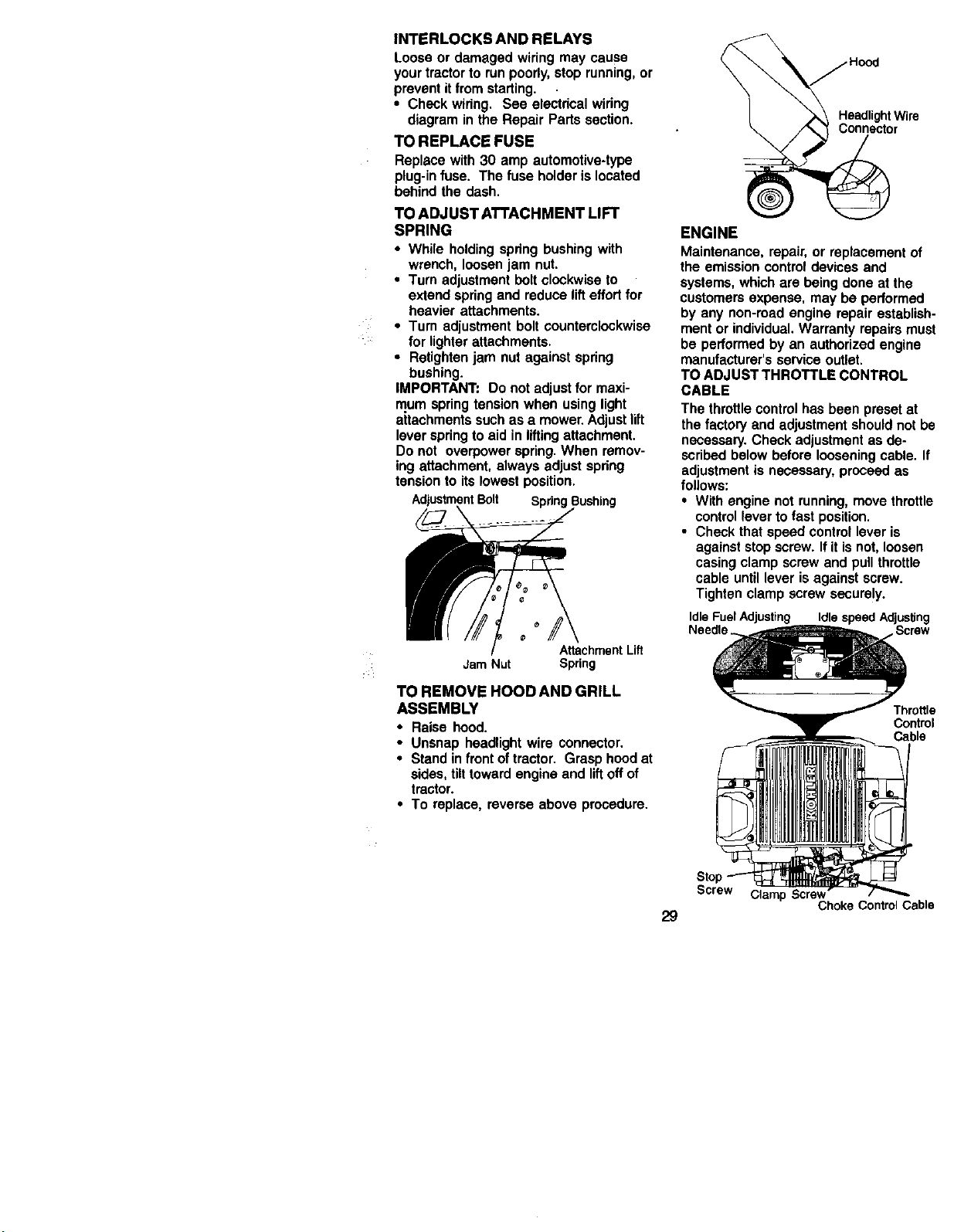
REPLACING BATI'ERY
/I, CAUTION: Do not short battery
terminals by allowing a wrench or any
other object to contact both terminals at
the same time, Before connecting battery,
remove metal bracelets, wristwatch
bands,rings,etc.
Positive terminal must be connected first
to prevent sparking from accidental
grounding.
• Lift hood to raised position.
• Remove terminal guard.
• Disconnect BLACK battery cable then
RED battery cable and carefully
remove battery from tractor.
• Install new battery with terminals in
same position as old battery.
• Reinstall terminal guard.
• First connect RED battery cable to
positive (+) battery terminal with hex
bolt and keps nut as shown. Tighten
securely.
• Connect BLACK grounding cable to
negative (-) battery terminal with
remaining hex bolt and keps nut.
Tighten securely
• Close terminal access doom.
• Close hood.
Terminal Keps Nut Hex Bolt
Access ._:,._
Door '°_ ....
siUve
Terminal (__ (Red)
Guard _ Cable
_J Z _Negative (BlaGk)
_,,-J Cable
TO REPLACE HEADLIGHT BULB
• Raise hood.
• Pull bulb holder out of the hole in the
backside of the grill.
• Replace bulb in holder and push bulb
holder securely back into the hole in
the backside of the grill.
28 • Close hood.
INTERLOCKS AND RELAYS
Loose or damagedwiringmay cause
yourtractorto runpoorly,stoprunning,or
preventitfromstarting.
• Checkwiring. See electdcalwiring
diagramin the Repair Partssection.
TO REPLACE FUSE
Replacewith30 amp automotive-type
plug-infuse. The fuse holderislocated
behindthe dash.
TO ADJUST ATTACHMENT LIFT
SPRING
• While holding spring bushing with
wrench, loosen jam nut.
• Turn adjustment bolt clockwise to
extend spring and reduce lifteffort for
heavier attachments.
• Turn adjustment bolt counterclockwise
for lighter attachments.
• Retighten jam nut against spring
bushing.
IMPORTANT: Do not adjust for maxi-
mum spring tension when using light
aitechments such as a mower. Adjust lift
lever spring to aid in lifting attachment.
Do not overpower spring. When remov-
ing attachment, always adjust spring
tension to its lowest position.
AdjustmentBolt Spring
AttachmentLift
Jam Nut Spring
TO REMOVE HOODAND GRILL
ASSEMBLY
• Raise hood.
• Unsnap headlightwire connector.
• Standinfrontoftractor. Grasphoodat
sides,tilttowardengineand liftoffof
tractor.
• To replace,reverseabove procedure.
HeadlightWire
Connector
ENGINE
Maintenance, repair, or replacement of
the emission control devices and
systems, which are being done at the
customers expense, may be performed
by any non-road engine repair establish-
ment or individual, Warranty repairs must
be performed by an authorized engine
manufacturer's service outlet.
TO ADJUST THROTTLE CONTROL
CABLE
The throttle control has been preset at
the factory and adjustment should not be
necessary. Check adjustment as de-
scribed below before loosening cable. If
adjustment is necessary, proceed as
follows:
• With engine not running, move throttle
control lever to fast position.
• Check that speed control lever is
against stop screw. If it is not, loosen
casing clamp screw and pull throttle
cable until lever is against screw.
Tighten clamp screw securely.
Idle Fuel Adjusting Idle speed Adjusting
Needle. Screw
Throttle
Control
Cable
Screw Clamp Screw
ChokeControlCable
29
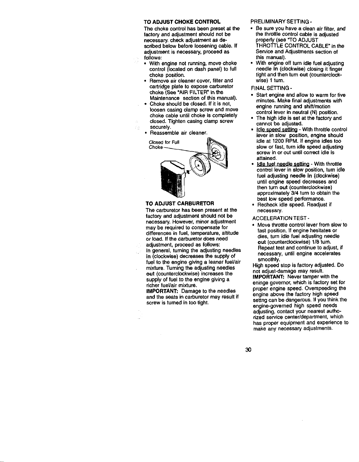
TO ADJUST CHOKE CONTROL
The choke control has been preset at the
factory and adjustment should not be
necessary, chock adjustment as de-
scdbed below before loosening cable. If
adjustment is necessary, proceed as
follows:
• With engine not running, move choke
control (located on dash panel) to full
choke position.
• Remove air cleaner cover, filter and
cartridge plate to expose carburetor
choke (See "A_R FILTER" in the
Maintenance section of this manual).
• Choke should be closed. If it is not,
loosen casing clamp screw and move
choke cable until choke is completely
closed. Tighten casing clamp screw
securely.
• Reassemble air cleaner.
Closed for Full
TO ADJUST CARBURETOR
The carburetor has been present at the
factory and adjustment should not be
necessary. However, minor adjustment
may be required to compensate for
differences in fuel, temperature, altitude
or load, If the carburetor does need
adjustment, proceed as follows:
In general, turning the adjusting needles
in (clockwise) decreases the supply of
fuel to the engine giving a leaner fueVair
mixture. Tuming the adjusting needles
out (counterclockwise) increases the
supply of fuel to the engine giving a
richer fueVair mixture.
IMPORTANT= Damage to the needles
and the seats in carburetor may result if
screw is turned in too tight.
PRELIMINARY SETTING.
• Be sure you have a clean air filter, and
the throttle control cable is adjusted
propedy (see =TO ADJUST
THROTTLE CONTROL CABLE" in the
Service and Adjustments section of
this manual).
• With engine off turn idle fuel adjusting
needle in (clockwise) closing it finger
tight and then turn out (counterclock-
wise) I tum.
FINAL SETTING -
• Start engine and allow to warm for five
minutes. Make final adjustments with
engine running and shift/motion
control lever in neutral (N) position.
• The high idle is set at the factory and
cannot be adjusted.
• Idle speed setting - With throttle control
lever in slow position, engine should
idle at 1200 RPM. If engine idles too
slow or fast, turn idle speed adjusting
screw in or out until correct idle is
attained.
• Idle fuel needle settina - With throttle
control lever in slow position, turn idle
fuel adjusting needle In (clockwise)
until engine speed decreases and
then turn out (counterclockwise)
approximately 3/4 turn to obtain the
best low speed performance.
• Recheck idle speed. Readjust if
necessary.
ACCELERATION TEST -
• Move throttle control lever from slow to
fast position, if engine hesitates or
dies, turn idle fuel adjusting needle
out (counterclockwise) 1/8 turn.
Repeat test and continue to adjust, if
necessary, until engine accelerates
smoothly.
High speed stop is factory adjusted. Do
not adjust-damage may result.
IMPORTANT: Never tamper with the
eninge governor, which is factory set for
proper engine speed. Overspeeding the
engine above the factory high speed
settng can be dangerous, it you think the
engine-governed high speed needs
adjusting, contact your nearest autho-
rized service center/department, which
has proper equipment and experience to
make any necessary adjustments.
30
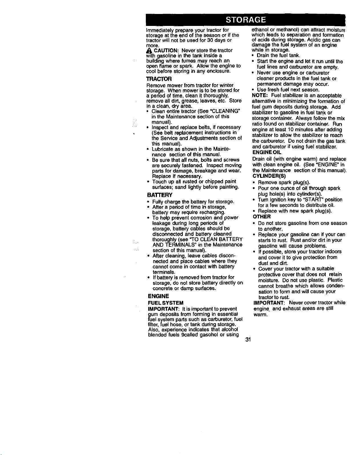
Immediatelyprepareyourtractorfor
storageat theend oftheseasonor ifthe
tractorwillnot beusedfor 30 daysor
more.
CAUTION: Neverstorethetractor
wuthgasolinein thetank insidea
buildingwhere fumes may reach an
openflameor spark. Allowtheengineto
coolbeforestonngin any enclosure.
TRACTOR
Removemowerfrom tractorfor winter
storage. When moweristo bestoredfor
a penodoftime,clean itthoroughly,
removeall dirt,grease, leaves,etc. Store
ina clean,dry area.
• Cleanentiretractor(See =CLEANING
in the Maintenancesectionofthis
manual).
• Inspectand replacebelts,ifnecessary
(See belt replacementinstructionsin
the ServiceandAdjustmentssectionof
this manual).
• Lubricateas showninthe Mainte-
nance sectionof thismanual.
• Be surethatall nuts,boltsand screws
are securelyfastened. Inspectmoving
partsfor damage,breakageand wear.
Replaceif necessary.
• Touch upall rustedor chippedpaint
surfaces;sand lightlybeforepainting.
BA'I-fERY
• Fullychargethe batteryfor storage.
• Aftera periodoftimeinstorage,
batterymay requirerecharging.
• To helppreventcorrosionand power
leakage duringlong periodsof
storage,batterycablesshouldbe
disconnectedand battery cleaned
thoroughly(see '9"0CLEAN BATTERY
AND TERMINALS"in the Maintenance
sectionofthismanual).
• Aftercleaning,leavecables discon-
nected and placecables where they
cannotcomein contactwithbattery
terminals.
• Ifbatteryisremovedfrom tractorfor
storage,do notstorebatterydirectlyon
concreteor damp surfeces.
ENGINE
FUELSYSTEM
IMPORTANT: Itisimportanttoprevent
gum depositsfrom forming inessential
fuel systempartssuchas carburetor,fuel
filter,fuel hose,or tankduringstorage.
Also, experienceindicatesthat alcohol
blendedfuels 9called gasoholor using
ethanolor methanol)canattractmoisture
whichleadsto separationand formation
ofacidsduringstorage.Acidicgascan
damagethefuel systemofan engine
whilein storage.
• Drainthefuel tank.
• Startthe engineand letit rununtilthe
fuel linesand carburetorare empty.
• Never use engineor carburetor
cleanerproductsin thefuel tankor
permanentdamage may occur.
• Use fresh fuel nextseason.
NOTE: Fuelstabilizerisan acceptable
alternativein minimizingtheformation of
fuel gumdepositsduringstorage. Add
stabilizerto gasolinein fuel tankor
storagecontainer.Alwaysfollow the mix
ratiofound on stabilizercontainer. Run
engineat least10 minutesafteradding
stabilizertoallowthestabilizerto reach
thecarburetor.Do notdrainthegastank
and carburetorifusingfuel stabilizer.
ENGINSOIL
Drainoil (withenginewarm)and replace
withcleanengineoil. (See =ENGINE"in
the Maintenance sectionofthismanual).
CYLINDER(S)
• Removesparkplug(s).
• Pourone ounceofoilthroughspark
plug hole(s)intocylinder(s).
• Turn ignitionkeyto "START"position
for a fewsecondsto distributeoil.
• Replacewithnew sparkplug(s).
OTHER
• Do not storegasolinefrom one season
toanother.
• Replaceyourgasolinecan ifyourcan
startstorust. Rustand/ordirtinyour
gasolinewillcause problems.
• Ifpossible,storeyourtractorindoors
and coveritto giveprotectionfrom
dustand dirt.
• Coveryourtractorwitha suitable
protectivecoverthatdoesnot retain
meisture. Do notuseplastic. Plastic
cannotbreathewhichallowsconden-
sationtoform and willcauseyour
tractortorust.
IMPORTANT: Nevercovertractorwhile
engine,and exhaustareas are still
warm.
31
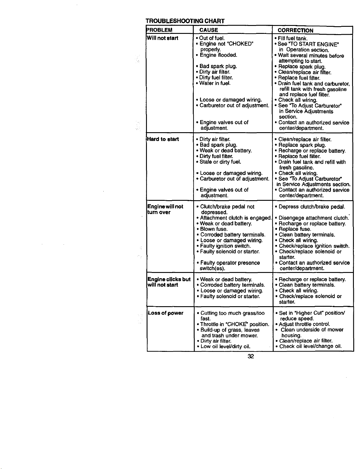
/ :
TROUBLESHOOTING CHART
)ROBLEM CAUSE CORRECTION
Will not start
Hard to start
Enginewill not
turn over
Engine clicks but
will notstart
Loss of power
• Out of fuel.
• Engine not "CHOKED"
properly.
• Engine flooded.
• Badspark plug.
• Dirtyairfilter.
• Dirtyfuelfilter.
• Water infuel.
• Looseor damagedwiring.
• Carburetoroutofadjustment.
• Enginevalvesout of
adjustment.
• Dirty air filter.
• Bad spark plug.
• Weak or dead battery.
• Dirty fuel filter.
• Stale or dirty fuel.
• Looseor damagedwiring.
• Carburetorout ofadjustment.
• Enginevalvesout of
adjustment.
• Clutch/brake pedal not
depressed.
• Attachment clutch is engaged.
• Weak or dead battery.
• Blown fuse.
• Corroded battery terminals.
• Loose or damaged wiring.
• Faulty ignition switch.
• Faulty solenoid or starter.
• Faultyoperatorpresence
switch(es).
•Weak or dead battery.
• Corroded batteryterminals.
• Looseor damagedwiring.
• Faultysolenoidor starter.
• Cutting too much grass/too
fast.
• Throttle in "CHOKE" position.
• Build-up of grass, leaves
and trash under mower.
• Dirty air filter.
• Low oil level/dirty oil.
32
• Fill fuel tank.
• See "TO START ENGINE"
in Operation section.
• Wait several minutes before
attempting to start.
• Replace spark plug.
• Clean/replace air filter.
• Replace fuel filter.
• Drain fuel tank and carburetor,
refilltank with fresh gasoline
and replace fuel filter.
• Check all wiring.
• See "To Adjust Carburetor"
in Service Adjustments
section.
Contact an authorized service
center/department.
• Clean/replace air filter.
• Replace sparkplug.
Recharge or replacebattery.
Replacefuel filter.
Drainfuel tankand refillwith
fresh gasoline.
• Checkall wiring.
• See "ToAdjustCarburetor"
in ServiceAdjustmentssection.
• Contactan authorizedservice
center/department.
• Depress clutch/brake pedal.
• Disengage attachment clutch."
• Recharge or replace battery.
• Replace fuse.
• Clean battery terminals.
• Check all wiring.
• Check/replace ignition switch.
• Check/replace solenoid or
I• starter.
Contact an authorized service
center/department.
• Recharge or replace battery.
• Clean battery terminals.
• Check all wiring.
• Check/replace solenoid or
starter.
• Set in "Higher Cut" position/
reduce speed.
• Adjust throttle control.
• Clean underside of mower
housing.
• Clean/replace air filter.
• Check oil level/change oil.
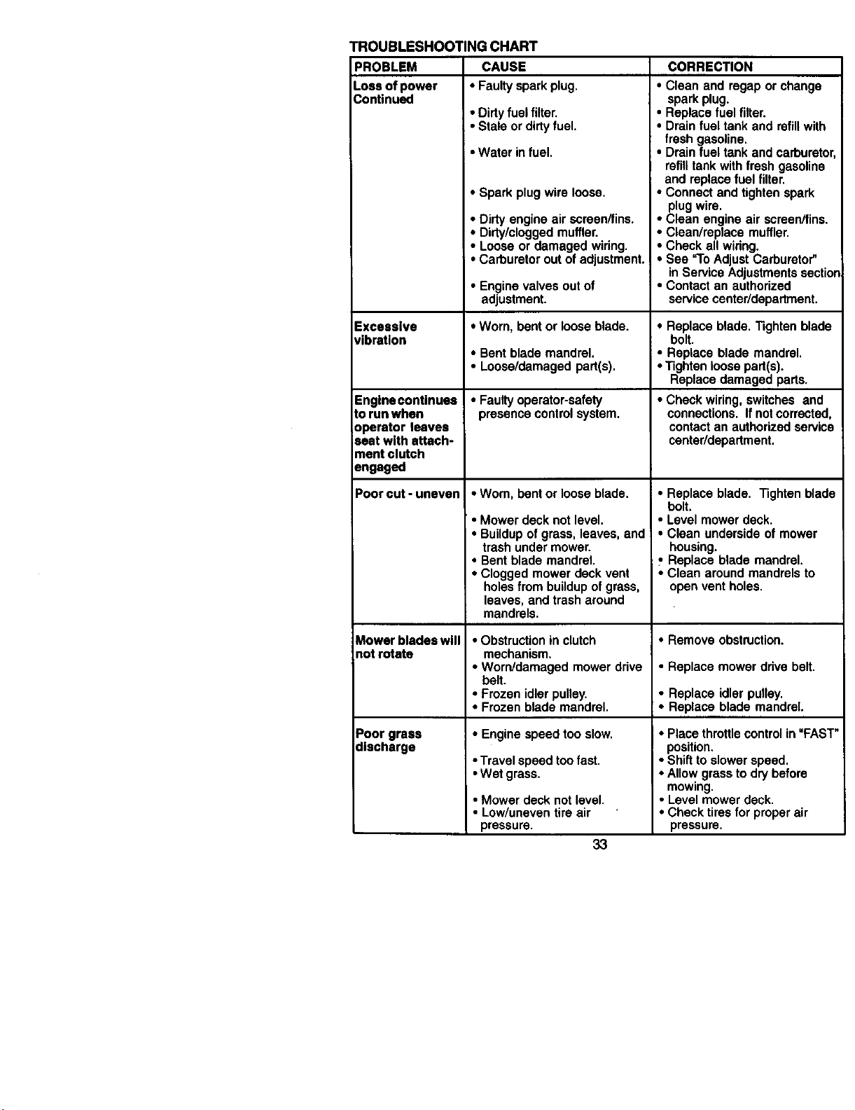
PROBLEM
Lossofpower
nontinued
TROUBLESHOOTING CHART
CAUSE
• Faultysparkplug.
• Dirtyfuelfilter.
• Staleor dirtyfuel.
• Water infuel.
Excessive
vibration
Engine continues
to run when
operator leaves
seat with attach-
ment clutch
engaged
Poor cut - uneven
Mower bladeswill
not rotate
Poor grass
discharge
• Spark plug wire loose.
• Dirtyengineair screen/fins.
• Dirty/cloggedmuffler.
• Looseor damagedwiring.
• Carburetoroutof adjustment.
• Enginevalvesoutof
adjustment.
• Worn,bentor looseblade.
• Bentblademandrel.
• Loose/damagedpart(s).
• Faultyoperator-safety
presencecontrolsystem.
• Worn,bentor looseblade.
• Mowerdecknot level.
• Buildupofgrass,leaves,and
trashundermower.
• Bent blademandrel.
• Cloggedmowerdeckvent
holesfrom buildupofgrass,
leaves,and trasharound
mandrels.
• Obstruction in clutch
mechanism.
• Worn/damaged mower drive
belt.
• Frozen idler pulley.
• Frozen blade mandrel.
• Engine speed too slow.
• Travel speed toofast.
• Wet grass.
• Mower deck not level.
• Low/uneven tire air
pressure.
33
CORRECTION
• Clean and rogapor change
sparkplug.
• Replacefuel filter.
• Drainfuel tankand refillwith
fresh gasoline.
• Drainfuel tankand carburetor,
refilltankwithfresh gasoline
and replacefuelfilter.
• Connectand tightenspark
plugwire.
• Clean engineair screen/fins.
• Clean/replecemuffler.
• Check allwiring.
• See "ToAdjustCarburetor"
in ServiceAdjustmentssection
• Contactan authorized
servicecenter/department.
• Replace blade, Tighten blade
bolt.
• Replace blade mandrel.
• Tighten loose part(s).
Replace damaged parts.
• Check wiring,switches and
connections.Ifnotcorrected,
contactan authorizedservice
center/department.
• Replace blade. Tighten blade
bolt.
• Level mower deck.
• Clean underside of mower
housing.
_,Replace blade mandrel.
• Clean around mandrels to
open vent holes.
• Removeobstruction.
• Replace mower drive belt.
• Replaceidlerpulley.
• Replaceblade mandrel.
• Place throttle control in "FAST"
position,
• Shift to slower speed.
• Allow grass to dry before
mowing.
• Level mower deck.
• Check tires for proper air
pressure.
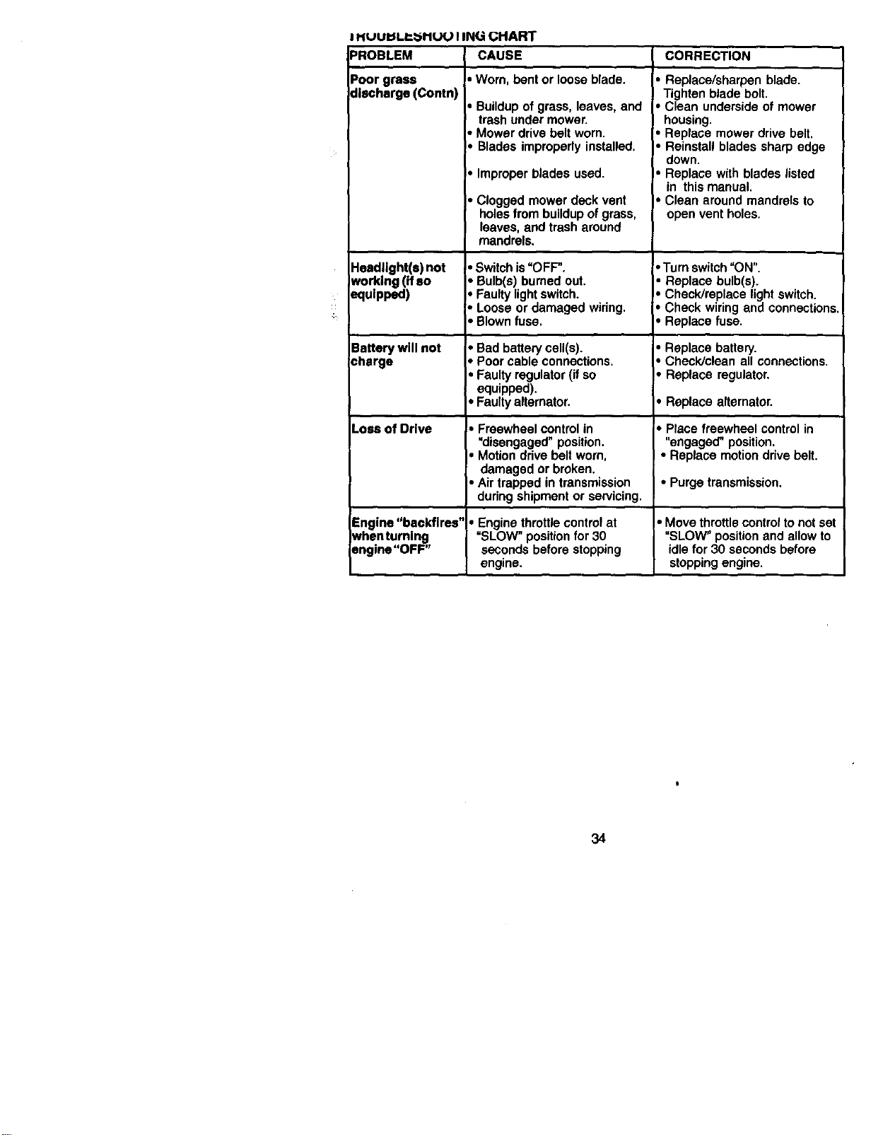
PROBLEM
Poorgrass
discharge(Contn)
IHUUI_I.P'_ItUUIINUGHART
CAUSE
• Worn, bent or loose blade.
Headlight(e)not
working(ifso
equipped)
Battery will not
charge
Loseof Drive
Buildup of grass, leaves, and
trash under mower.
Mower drive belt worn.
Blades impropedy installed,
Improperbladesused.
• Cloggedmowerdeckvent
holesfrombuildupof grass,
leaves,and trasharound
mandrels.
• Switchis"OFF".
• Bulb(s)burnedout.
Faultylightswitch.
Loose or damagedwiring.
• Blownfuse.
• Bad batte_cell(s).
• Poor cable connections,
• Faulty regulator (if so
equipped),
• Faulty alternator.
• Freewheelcontrolin
=disengaged"position.
• Motiondrivebeltworn,
damagedor broken.
• Airtrappedin transmission
duringshipmentor servicing.
CORRECTION
• Replace/sharpen blade.
Tighten blade bolt,
• Clean underside of mower
housing.
• Replace mower drive belt.
• Reinstall blades sharp edge
down.
• Replace with blades listed
in this manual.
• Clean around mandrels to
open vent holes.
• Turn switch "ON".
• Replace bulb(s).
• Check/replace light switch.
• Check wiring and connections,
• Replace fuse.
• Replace battery.
• Check/clean all connections,
• Replace regulator.
• Replacealternator.
• Place freewheel control in
"engaged" position,
• Replace motion drive belt.
• Purge transmission.
Engine "bacldlres" • Engine throttle control at • Move throttle control to not set
Nbenturning "SLOW" position for 30 "SLOW" position and allow to
Dngine"OFF" seconds before stopping idle for 30 seconds before
engine, stopping engine.
34
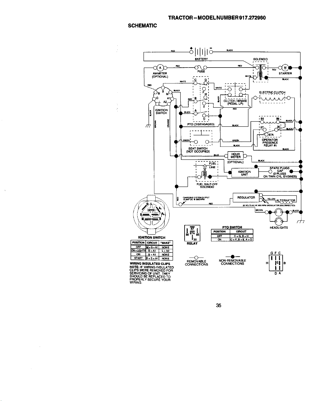
SCHEMATIC
TRACTOR - MODEL NUMBER 917.272960
AED
AMMETER
(OPTIONAL)
I_ITE
)B s
G
GNITIOr
SWITCk
IGNITION SWITCH
POSIA_R_T CIRCUIT "MAKE"
OFF M*G._A1 NONE
ON* B÷A1 L÷A2
ON 8+At NC_NE
S B+S*AI N(_NE
WIRING INSULATED CUPS
NOTE: IF WIRING INSULATED
CLIPS WERE REMOVED FOR
SERVICING OF UNIT. THEY
SHOULD BE REPLACED TO
PROPERLY SECURE YOUR
W_RING
CLUTCH / BRAKE
(PEDAL UP)
RED
i
PTO (DISENGAGED) e_
i
SEAT SWITCH
(NOT OCCUPIED]
L ........
L b
FUEL SHUT.OFF
SOLENOID
RELAY
(OPTIONAL)
A SPARKPLUGS
,aNmON_(2 G_S
UNIT
J ON "P_NIN CYL. ENGINES)
REGULATO_
_ VOLTSACe _ RPMC_O_ATOAO_CC_e4EC1ED)
Pro SWITCH HEADLIGHTS
pOSITION _ CIRCUIT
OFF C+GrB*H
ON *FrB÷ErA+D
REMOVABLE
CONNECTIONS
GFC
- N
NON-REMOVABLE
CONNECTIONS H E
DA
35
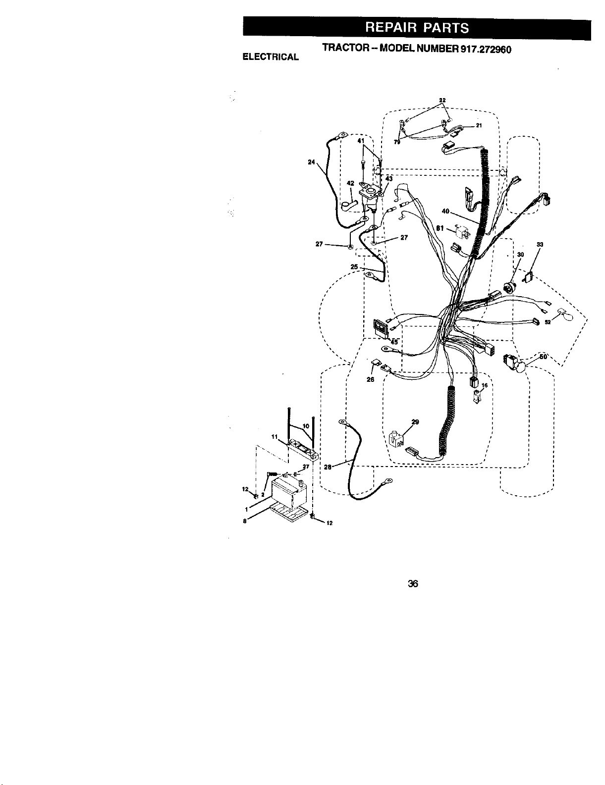
TRACTOR -- MODEL NUMBER 917.272960
ELECTRICAL
24
33
36
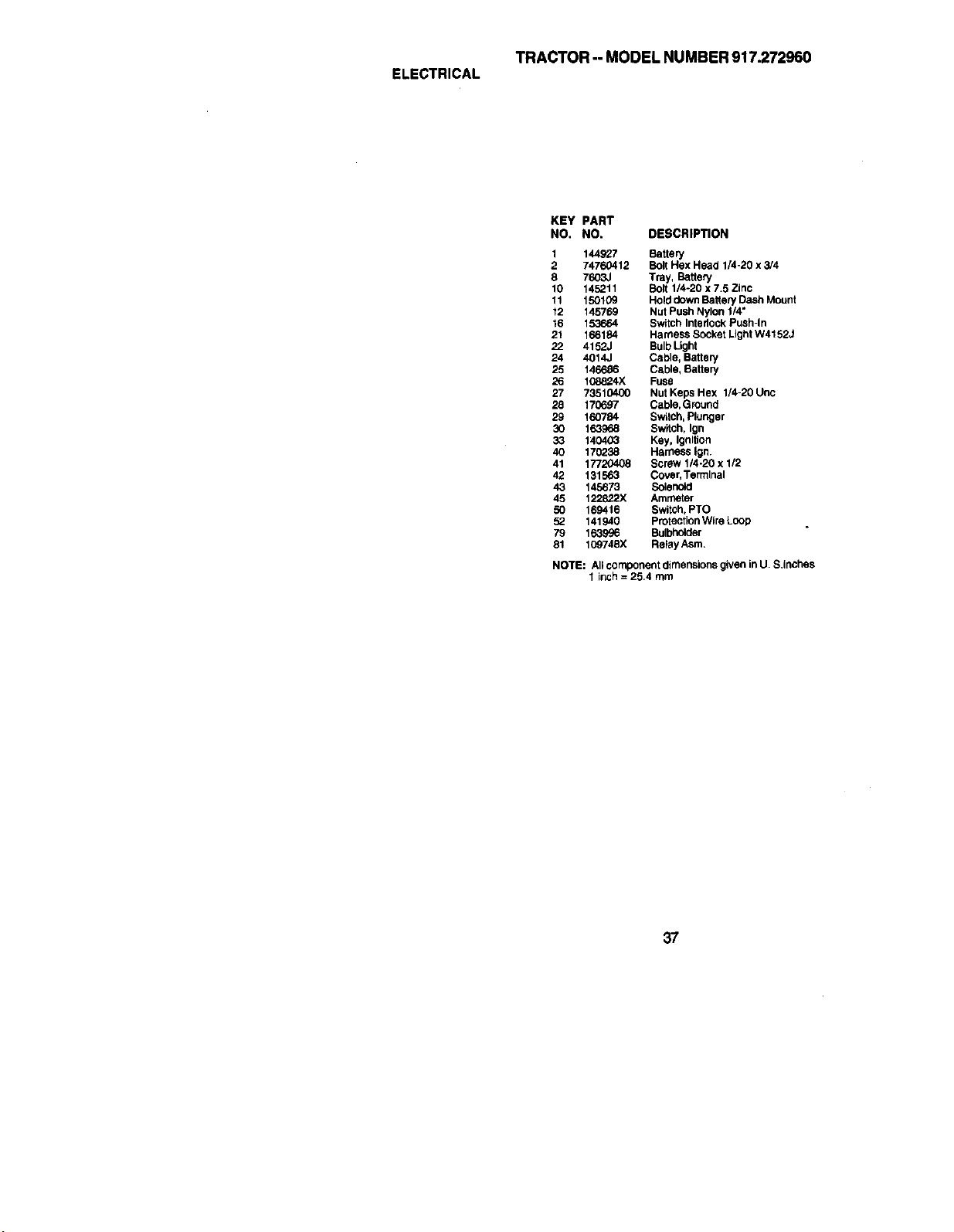
TRACTOR-- MODEL NUMBER 917.272960
ELECTRICAL
KEY PART
NO. NO. DESCRIPTION
1 144927 Battery
2 74760412 Bolt Hex Head 1/420 x 3/4
8 7603J Tray, Battery
10 145211 Bo_t 1/4-20 x 7 5 Zinc
11 150109 Hold down Battery Cash Mount
12 145769 Nut Push Nylon 1/4"
16 153664 Switch Interlock Push-In
21 166184 Harness Socket Light W41523
22 4152J Bulb Light
24 4014J Cable, Battery
25 146686 Cable, Battery
26 108824X Fuse
27 73510400 Nut Keps Hex 1/4-20 Unc
28 170697 Cable,Ground
29 160784 Switch, Plunger
30 163968 Switch, Ign
33 140403 Key, Ignition
40 170238 Harness Ign.
41 177L:_408 Screw 114-20 x I/2
42 131563 Covsr, Termlnal
43 145673 Solenoid
45 122822)( Ammeter
50 169416 Switch, PTO
52 141940 Protection Wire Loop
79 le39_6 Bulbholder
81 109748X Relay Asm
NOTE: All component dimensions given in U. S,inches
1 inch = 25.4 mm
37
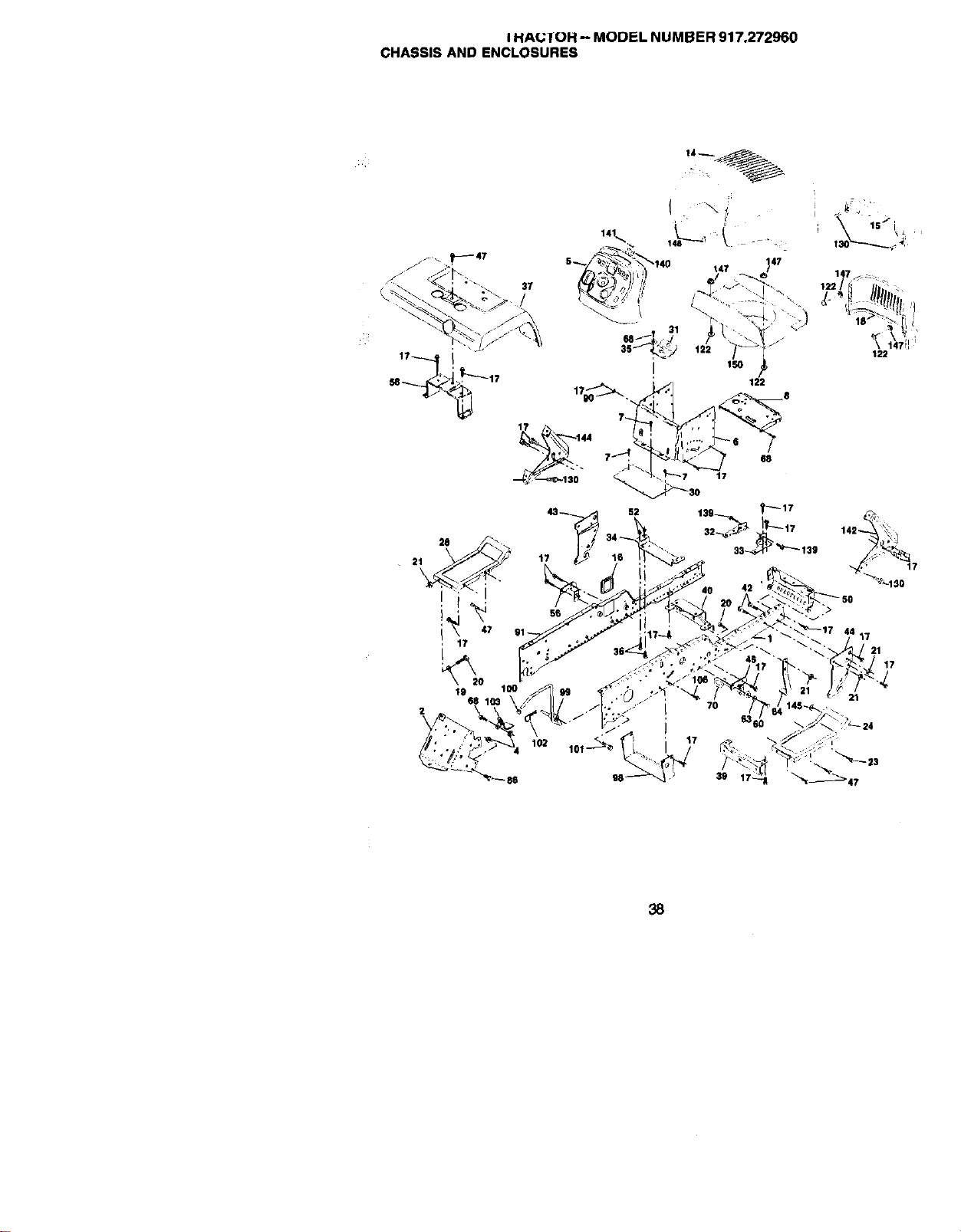
I HA(.;1OR -- MODEL NUMBER 917.272960
CHASSIS AND ENCLOSURES
37
17
/
88
31t
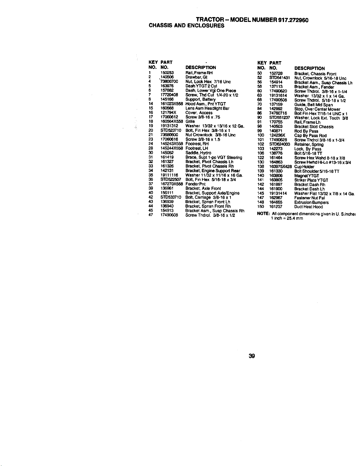
TRACTOR - MODEL NUMBER 917.272960
CHASSIS AND ENCLOSURES
KEY PART
NO. NO,
I 155253
2 14O5O6
4 "738007(30
5 163976
6 157882
7 17720408
8 145166
14 161023X558
15 160r"_
16 121794X
17 17060612
18 160564X558
19 19131312
20 STD523710
21 7368_600
23 17060616
24 145243X558
28 145244X558
30 145(T02
31 161419
52 161327
33 161326
34 142131
35 19111116
36 s'rD522507
37 167270X558
39 136961
40 156111
42 STD552710
43 136939
44 136940
45 154913
47 17490608
• KEY PART
DESCRIPTION NO. NO. DESCRIPTION
RaN, FrameRH 50 152728 Bracket, Chassis Front
Drewbar, Gt 52 STD541431 Nut, Crownlock 5/16-18Unc
Nut, Lock Hex 7/16 Uric 56 154814 Bracket Asm,, Susp Chassis Lh
Dash YTGT 2 Cyl 58 137113 Brecket Asm,, Fender
Dash, Lower Vgt One Piece 60 17490620 Screw Thdrol. 3/8-16 x 1-I/4
Screw, Thd Cut 1/4-20 x 1/2 63 19131614 Washer 13/32 x 1 x 14 Ga.
Suppod, BatteP/ 68 17490508 Screw TIxIrol. 5/16-18 x 1/2
Hood Asm., Pnt YTGT 70 137159 Guide, Belt Mid Span
Lens Asm Headlight Bar 84 142992 Stop, Over Center Mower
Cover, Access 86 74760716 Bo_tFin Hex 7/16-14 UNC x 1
Screw 3/8-16 x .75 90 8TD551237 Washer, Lock Ext. Tooth 3/8
Gr_le 91 170755 Rail, Frame Lh
Washer 13/32 x 13/16 x 12 Ga. 98 140503 Bracket Skid Chassis
Bolt, Fin Hex 3/8-16 x 1 99 140671 Rod By Pass
Nut Crownlook 3/8-16 Uric 100 124236X Cap By Pass Rod
Screw 3/8-16 x 1,5 101 17490628 Screw Thdrol 3/8-16 x 1-3/4
Fontrest, RH 102 STD_4003 Retainer, Spring
Footrest, LH 103 142273 Look, By Pass
Saddle, Hydro 106 138776 Bait 5/16-18 "n"
Brace, Supt 1-pc VGT Steedng 122 161464 Screw Hex Wshd 8-18 x 7/8
Bracket, Pivot Chassis Lh 130 164863 ScrewHwhdHi-Lo#13-16x3/4
Bracket, Pivot Chassis Rh 138 163975X428 CupHolder
Bracket, Engine Support Rear 139 161330 Bolt Shoulder 5/16-18 TT
Washer 11/32 x 11/16 x 16 Ga. 140 163806 MagnetYTGT
Bolt, Fkl Hex 5/16-18 x 3/4 141 163805 Stdker Plate YTGT
Feoder Pnt 142 161897 Bracket Dash Rh
Bracket, Axle Front 144 161900 Bracket Dash Lh
Bracket, Support Axle/Engine 145 19131414 Washer Flat 13/32 x 7/8 x 14 Ga,
Bolt, Carhage 3/8-16 x 1 147 162967 Fastener Nut Pal
Bracket, Spnsn Front Lh 148 164655 Extrusion Bumpers
Bracket, Spcsn Front Rh 150 161237 Duct Heat Hood
Bracke( Asm,, Susp Chassis Rh
Screw ThdroL 3/8-16 x 1/2 NOTE: All component dimensions given in U, S,Incha_
1 inch = 25.4 mm
39
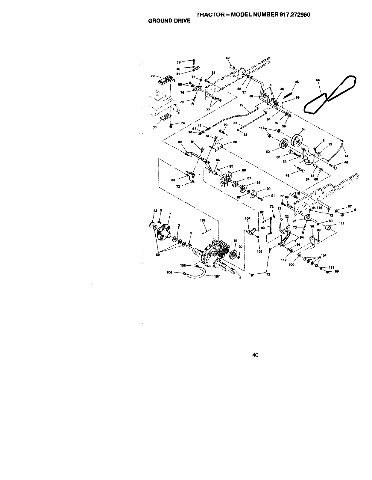
IHACTOR -- MODEL NUMBER 917.272960
GROUND DRIVE
40
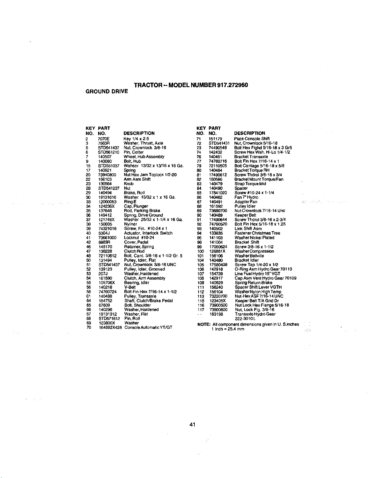
TRACTOR -- MODEL NUMBER 917,272960
GROUND DRIVE
KEY PART KEY PART
NO, NO. DESCRIPTION NO. NO.
2 7070E Key 114 x 2.5 71 151179
3 756.3R Washer, Thrust, Axle 72 $1_541431
5 STD541437 Nut, Crownlock 3/8-16 73 74490548
6 STD561210 Pin, Cotter 74 142432
7 140507 Wheel, Hub Assembly 76 140481
9 140080 Bolt, Hub 77 74760716
15 STD551037 Wahser 13/32. x13/16x16Ga. 79 72110505
17 140921 Spring 80 140484
20 73940800 Nut Hex Jam Toplock 1/2-20 81 17490612
22 156103 Arm Asm Shift 82 150586
23 130564 Knob 83 140479
28 STD541237 Nut 84 140490
29 140494 Brake, Rod 85 17541026
30 19131616 Washer t3/32 x 1 x 16 Ga. 86 140462
33 12000053 RingE 87 140491
34 124236X Cap, Plunger 88 161592
35 137648 Rod. Parking Brake 89 73680700
36 149412 Spring, Drive Ground 90 140489
37 121749X Washer 25/32 x 1-1/4 x 16 Ga. 91 17490644
38 150035 Nyliner 92 74760526
39 74321016 Screw, Fin. #10-24 x 1 9_ 140502
46 5304J Actuator, Interlock Switch 94 133835
41 73661000 Locknut #10-24 96 141103
42 8883R Cover, Pedal 98 141004
46 145170 Retainer, Spring 99 17060624
47 138226 Clutch Rod 100 126881X
48 72110612 Bolt, Can'i. 3/8-16 x 1-1/2 Gr, 5 101 156106
50 131494 Pulley, Idler, Flat 104 140480
51 STD541437 Nut, Crownlock 3/8-16UNC 105 17580408
52 139123 Pulley, fdler, Grooved 106 142918
53 207J Washer, Hardened 167 154739
54 161590 Clutch, Arm Assembly 108 142917
55 105706X Bearing, Idler 109 140929
56 140218 V-Belt 111 156240
58 74760724 Bolt Ftn Hex 7/16-14 x 1-1/2 112 156104
61 140488 Pulley, Transaxle 113 73220700
64 154752 Shaft, ClutchfBrake Pedal 115 123405X
65 67609 Bolt, Shoulder 116 73900500
66 140296 Washer, Hardened 117 73900600
67 19131312 Washer, Flat -- 163198
68 STD571812 Pin, Roll
69 123800X Washer
70 164692X428 Console Automatic YT/GT
DESCRIPTION
Plate Console Shift
Nut, Crownlock 5/16-18
Bolt Hex FIghd 5/16-18 x 3 Gr5
Screw Hex Wsh. HI-Lo 1/4-1/2
Bracket Transaxle
Bolt Fin Hex 7/16-14 x 1
Bctt Carriage 5/16-18 x 5/8
Bracket Torque RH
Screw Thdrct 3/8-16 x 3/4
Bracket Mount Torque/Fan
StrapTorque Mid
Spacer
Screw #10-24 x 1-1/4
Fan 7" Hydro
Adapter Fan
Pulley Idler
Nut Crownfock 7/16-14 Unc
Keepar Belt
Screw Thdrol 3/8-16 x 2-3/4
Bctt Fin Hex 5/16-18 x 1.25
Link Shift Asm
Fastener Christmas Tree
Washer Nickel Plated
Bracket Shift
Screw 3/6-16 x 1-1/2
Washer Compression
Washer Bellville
Bracket Idler
Screw Tap 1/4-20 x 1/2
O-Ring Asm Hydro Gear 70110
Line Fuel Hydro 15" VGT
Cap Asm Vent Hydro Gear 70169
Spring Return Brake
Spacer Shift Lever VGTH
Washer Nylon High Temp
Nut-HexASFT/16-14UNC
Keeper Belt T/A Grid Dr
Nut Lock Hex Flange 5/16-18
Nut, Lock Fig. 3/8-16
Transaxle Hydro Gear
222-3010 L
NOTE: All component dimensions given in U.S.inches i
I inch = 25.4 rnm
41
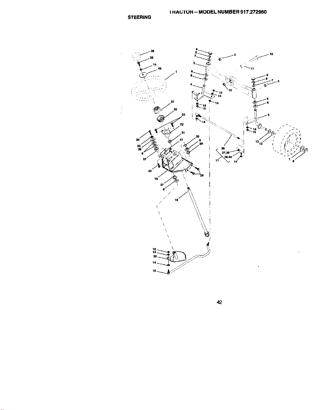
I HAUTOH -- MODEL NUMBER 917.272960
STEERING
9
1 6_
31
37,39 "_!
17 _ 14
42
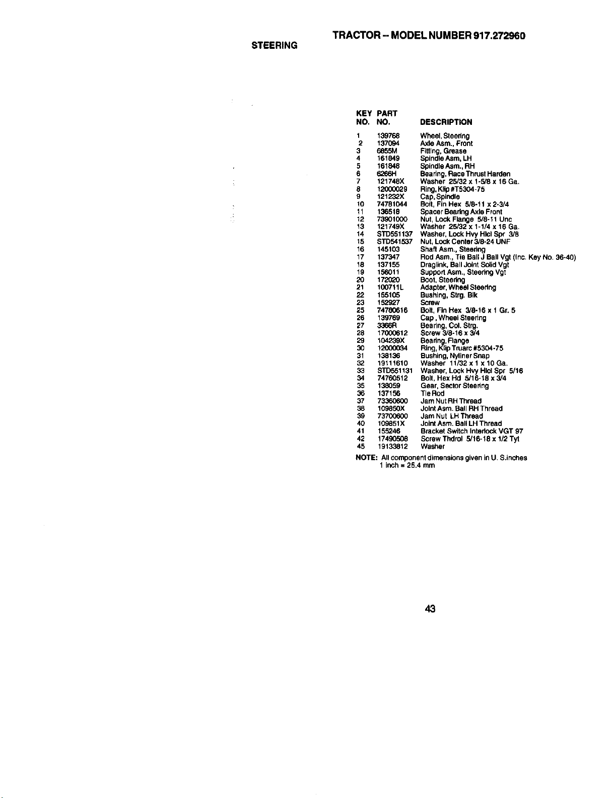
TRACTOR--MODELNUMBER917.272960
STEERING
KEY PART
NO. NO. DESCRIPTION
1 139768
2 137094
3
4 161849
5 161848
6 6266H
7 121748X
8 12000029
9 121232X
10 74781044
11 136519
12 73901000
13 121749X
14 STD551137
15 STD541537
16 145103
17 137347
18 137155
19 156011
20 172020
21 1007tlL
22 155105
23 152927
25 74780616
26 139769
27 3366R
28 17000612
29 104239X
3O 12O0OO34
31 138136
32 19111610
33 STD551131
34 74760512
35 138059
36 137156
37 73360600
38 10983OX
39 73700600
40 109851X
41 155246
42 17490508
45 19133812
NOTE:
Wheel, Steering
Axle Asm., Front
Fitting, Grease
Spindle Asm, LH
Spindle Asm., RH
Bearing, RaceThrust Harden
Washer 25/32 x 1-5/8 x 16 Ga.
Ring, Klip #T5304+75
Cap, Spindle
Bolt, Fin Hex 5/8-11 x 2-3/4
Spacer Beadng Axle Front
Nut, Lock Flange 5/8-11 Uric
Washer 25/32 x 1-1/4 x 16 Ga.
Washer, Lock Hvy Hlcl Sp¢ 3/8
Nut, Lock Center 3/8-24 UNF
Shaft Asrn., Steering
Rod Asm., Tie Ball J Ball Vgt (Inc. Key No. 36-40)
Draglink, Boll Joint S_id Vgt
Suppod Asm., Steering Vgt
Boot, Steering
Adapter, Wheel Steedng
Bushing, Strg. BIk
Screw
Bolt, Fin Hex 3/8-16 x 1 Gr. 5
Cap, Wheel Steenng
Bearing, Col. Strg.
Screw 3/8-16 x 3/4
Beadng, Flange
Ring, Klip Truarc #5304-75
Bushing, Nyliner Snap
Washer 11/32 x 1 x 10 Ga+
Washer, Lock H W Hlcl Spr 5/16
Bolt, Hex Hd 5/16-18 x 3/4
Gear, Sector Steering
Tie Rocl
Jam Nut RH Thread
Joint Asm. Ball RH Thread
Jam Nut LH Thread
Joint Asm. Ball LH Thread
Bracket Switch Interlock VGT 97
Screw Thdrol 5/16-18 x 112Tyt
Washer
AllcomponentdimensionsgiveninU, S.inches
1 inch= 25.4 mm
43
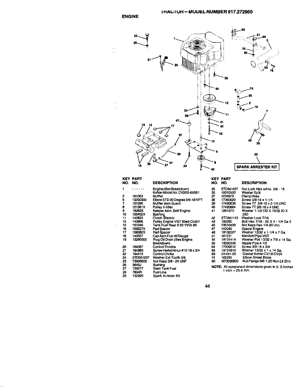
I HAL; I UH -- MUUI:L NUMBER 917.272960
ENGINE
18 te
17 ' _42
37 i _ _ 43
KEY
NO,
1
2
5
7
8
9
10
11
12
15
16
17
18
19
20
21
22
24
25
26
27
28
29
16
PART
NO.
161063
13200300
1513_6
121361X
15(_828
105432X
140923
143996
151346
10g_27X
106082X
140527
132903O0
164067
164863
164415
_1237
73920600
3645J
139277
7834R
13292O
4O
29
\
[ SPARK ARRESTER KIT [
KEY PART
DESCRIPTION NO. NO. DESCRIPTION
Englne(SeeBreakdown) 33 _1437 Nut Lock Hex w/ins. 3/8 - 16
Kohler Model No. CV2OS-65561 35 10010500 Washer Split
Muffler 37 123487X Clarnp Hose
Elbow STD 90 Degree 3/8- t6 N PT 38 17060620 Screw 3/8-15 x 1-1/4
Muffler Asm Guard 39 1749G636 Screw TT 3/8-15 x 2-1/4 UNC
Pulley V-Idler 40 17490664 Screw ]-r 3/8-16 x 4 UNC
Keeper Asm. Belt Engine 41 126197X Washer 1-1/20D X t 5/32 ID X
Bushing .250
Clutch Electric 42 STD551143 Washer Lock 7/16
Pulley Engine VGT Elect Clutch 43 150280 Bolt Hex 7/15 - 25 X 4 - 1/4 Ga 5
Tank Fuel Rear 3.50 Yt/Gt 96 45 73510400 Nut Keps Hex 1/4-25 Unc
Pad Spacer 47 142040 Spacer Engine
Pad Spacer 48 19132007 Washer 13/32 x 1-1/4 x 7 Ga.
CapAsm Fue_W/Gauge 51 161231 Manifold PIpeVGT
Plug OII Drain (See Engine 54 19131414 Washer Flat 13/32 x 7/8 x 14 Ga.
Bneakdown) 55 13280336 Nipple Plpa 4.1/2
Control Throltle 64 17000612 Borew 5/8-16 x 5/4
Borew Hwhd HI-Lo #13-16 x 3/4 65 19131614 Washer 13/32 x 1 x 14 Ga.
ControiCboke 69 24-041-02 Gasket Kohler CV 15-CV25
Washer Ext Tooth 3/8 74 162295 Elbow Street Brass
Nut Keps 3/8 - 24 UNF 80 M7303(_00 Nut Flange M8-1.25 Non-Lk Zink
Bushing
Stem Tank Fue_ NOTE: Allcomponent dimensions given in U+$.inches
1 inch = 25,4 mm
Fuel Line
Spark Arrester Kit
44
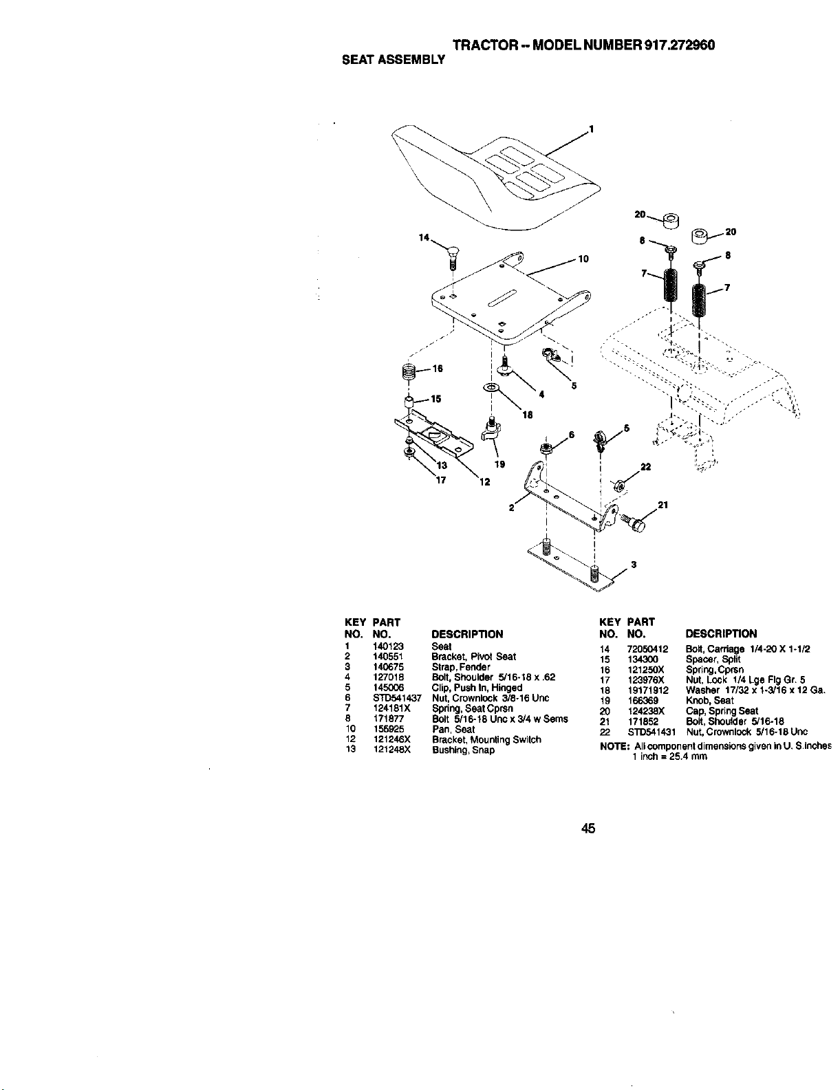
TRACTOR-- MODEL NUMBER 917.272960
SEAT ASSEMBLY
KEY PART
NO. NO.
1 140123
2 140551
3 140675
4 127018
5 145006
6 STD541437
7 124181X
8 171877
10 155925
12 121246X
13 121248X
DESCRIPTION
Seat
Bracket,PivotSeat
Strap,Fender
Bolt, Shoulder 5/16-18 x .62
Clip, PushIn, Hinged
Nut,Crownlock3/8-16Uric
Spring,SeatCprsn
Bolt 5/16-t8 Uncx 3/4 w Sems
Pan,Seat
Bracket,MountingSwitch
Bushing,Snap
KEY
NO.
14
15
16
17
18
19
2O
21
22
PART
NO. DESCRIPTION
72050412 Bolt, Carnage 1/4-20 X 1-1/2
134300 Spacer, Split
121250X Spring,Cprsn
123976X Nut, Lock 1/4 Lge Fig Gr. 5
19171912 Washer 17/32 x t-3/16 x 12 Ga.
166369 Knob, Seat
124238X Cap, Spring Seat
171852 Bolt, Shoulder 5/16-18
STD541431 Nut, Crownlock 5/16-18Unc
NOTE: Allcomponent dimensions given in U. S.Inches
1 inch = 25.4 mm
45
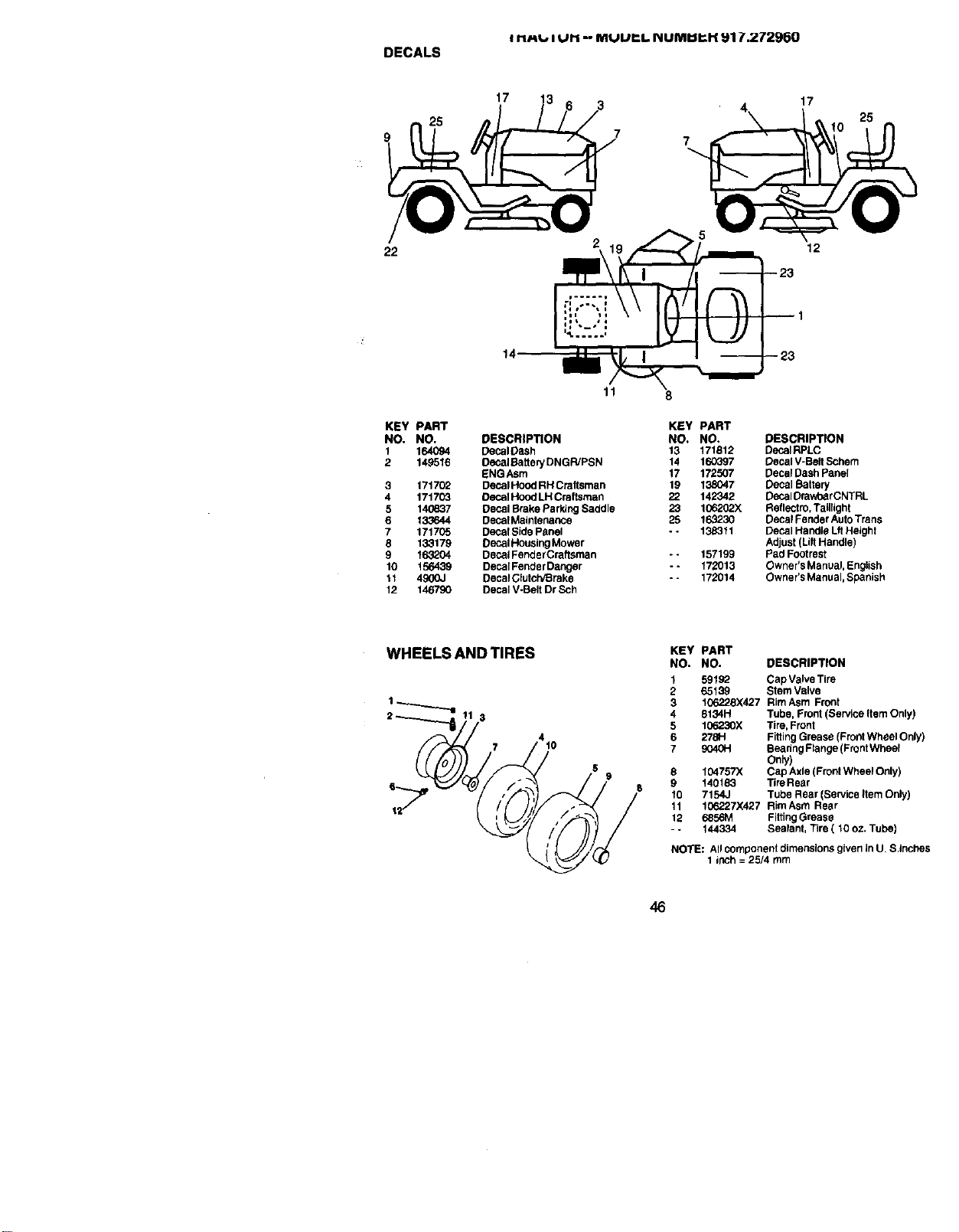
t rt_, iPM -- MUUI:I. I_IUMUI;H _17.272960
DECALS
17
7
17
22
14
11 8
KEY PART
NO, NO, DESCRIPTION
1 164094 DecalDseh
2 149518 DecaJBatterj DNGWPSN
ENGAsm
3 171702 DecalHood RH Craftsman
4 171703 Decal Hood LH Craftsman
5 146837 Decal Brake Parking Saddle
6 13,3644 DecalMalntenance
7 171705 Decal Side Panel
8 133179 Decal Housing Mower
9 163204 Decal FenderCraltsman
10 156439 DecalFender Danger
11 4900J Decal ClutclVBrake
12 146790 Decal V-Belt Dr Sch
1
--'-23
KEY PART
NO. NO. DESCRIPTION
13 171812 DecalRPLC
14 160597 Decal V-Belt Schern
17 172507 Decal Dash Panel
19 138047 Decal Battery
22 142342 Decal Orav/earCNTRL
23 106202X Reflect to, Taillight
25 163230 Decal Fender Auto Trans
- - 138311 Decal Handle Lit Height
Adjust (Lilt Handle)
- - 157199 Pad Footrest
-- 172013 Owner's Manual, English
- - 172014 Owner's Manual, Spanish
WHEELS AND TIRES
4
? t0
8
9
10
11
12
KEY PART
NO. NO. DESCRIPTION
1 59192 CapValveTire
2 65139 StemValve
3 106228)(427 RimAsm Front
4 8134H Tube,Front(ServiceItemOnly)
5 106230X Tire,Front
6 278H FittingGrease (FrontWheel Only)
7 9040H BeadngRange (FrontWbeef
Only)
104757X Cap Axle(FrontWheelOnly)
140183 TireReer
7154J TubeRear(ServiceItemOnly)
106,?.27X427RimAsm Rear
6856M FittingGrease
144334 Sealant,Tire ( 10oz. Tube)
NOTE: All component dimensions given in U. S,inches
1 inch = 25/4 rnrn
46
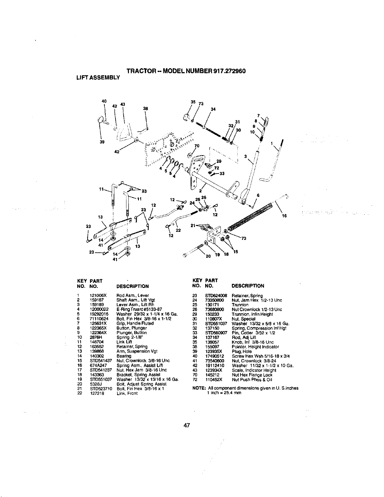
TRACTOR- MODEL NUMBER 917.272960
LIFTASSEMBLY
13
23
13
12
22
12
'20 19 18
6
19
16
KEY
NO.
1
2
3
4
5
6
7
8
9
10
11
12
13
14
15
16
17
18
19
20
21
22
PART
NO.
121C_6X
159187
159189
12000022
19292016
71110624
125631X
122365X
122364X
2876R
146704
163552
139868
140302
STD541437
674A247
STB541237
143363
STD551037
5328J
STB523710
127218
DESCRIPTION
Rod Asm,, Lever
Shaft Asm., Lift Vgt
Lever Asm., Lift Rh
E-RIngTruarc#5133-87
Washer 23/32 x 1-1/4 x 16 Ga,
Boll, Fin Hex 3/8-16 x 1-1/2
Grip, Handle Fluted
Button, Plunger
Plunger, Button
Spring 2-1/8"
Link Lift
Retainer, Spring
Arm, Suspension Vgt
Beadng
Nut, Crownloek 3/8-16 Unc
Spring Asm., Assist Lift
Nut, Hex Jam 3/8-16 Unc
Bracket, Spdng Assist
Washer 13132 x 13/16 x 16 Ga.
Bolt, Adjust Spring Assist
Bolt, Fin Hex 3/8-16 x 1
Link, Front
KEY PART
NO. NO. DESCRIPTION
23
24
25
26
29
3O
31
32
33
34
35
38
39
4O
41
42
43
7O
72
S'rD624O08 Retainer, Spring
73350800 Nut, Jam Hex 1/2-13 Unc
130171 Trunnion
73680800 Nut Crownlock 1/2-13 Unc
150233 Trunnion, Infin Height
110807X Nut, Special
STD551037 Washer 13/32 x 5/8 x 16 Ga.
137150 Spdng, Compression Inf Hgt
s'rD560907 Pin, Cotter 3/32 x 1/2
137167 Rod, Adj Lift
138057 Knob, Inf 3/8-16 Unc
155097 Pointer, Height Indicator
123935X Plug, Hole
17490512 Screw Hex Wsh 5/16-18 x 3/4
73540600 Nut, Crownlock 3/8-24
19112410 Washer 11/32 x 1-1/2 x 10 Ga.
123934X Scale, Indicator Height
145212 Nut Hex Flange Lock
110452X Nut Push Phos & Oil
NOTE: All component dimensions given in U, S.inches
1 inch = 25,4 rnm
47
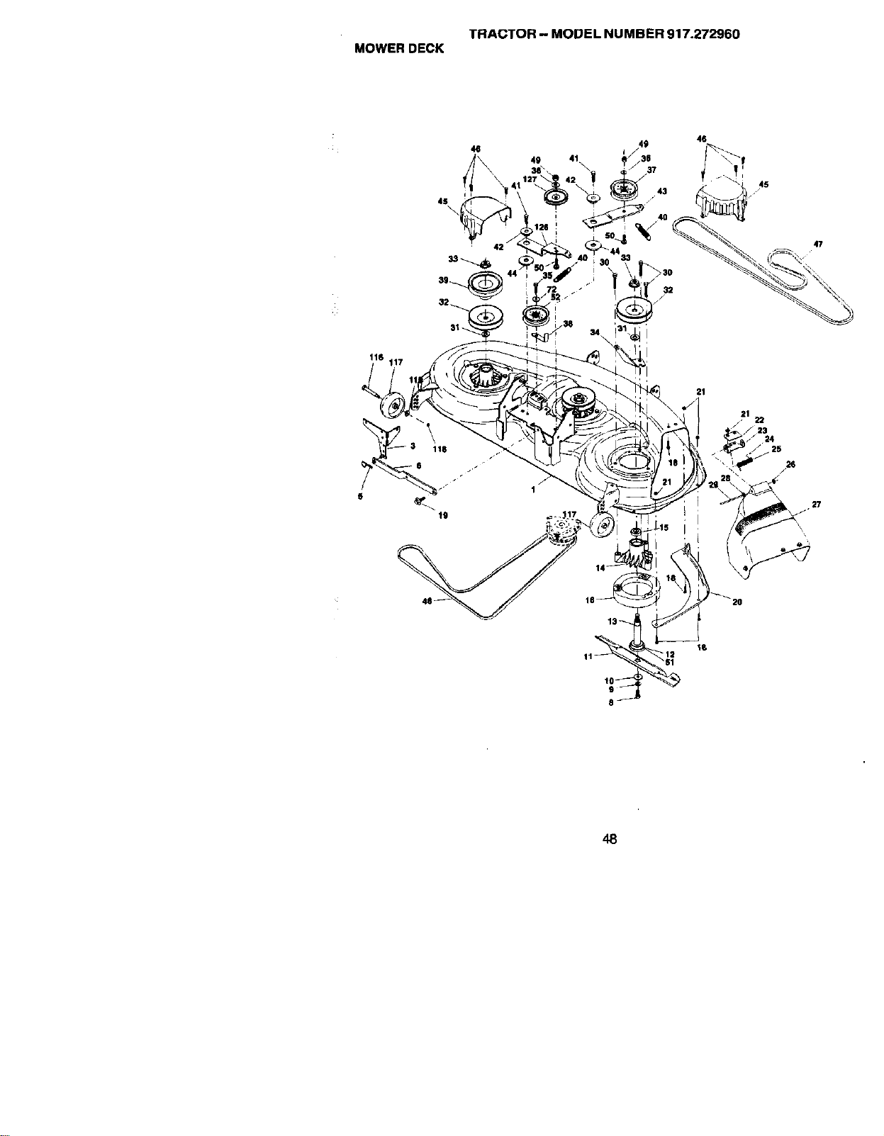
TRACTOR -- MODEL NUMBER 917.272960
MOWER DECK
4S
\
49 41 ,36
46
45
116
47
21
12
"Sl
48
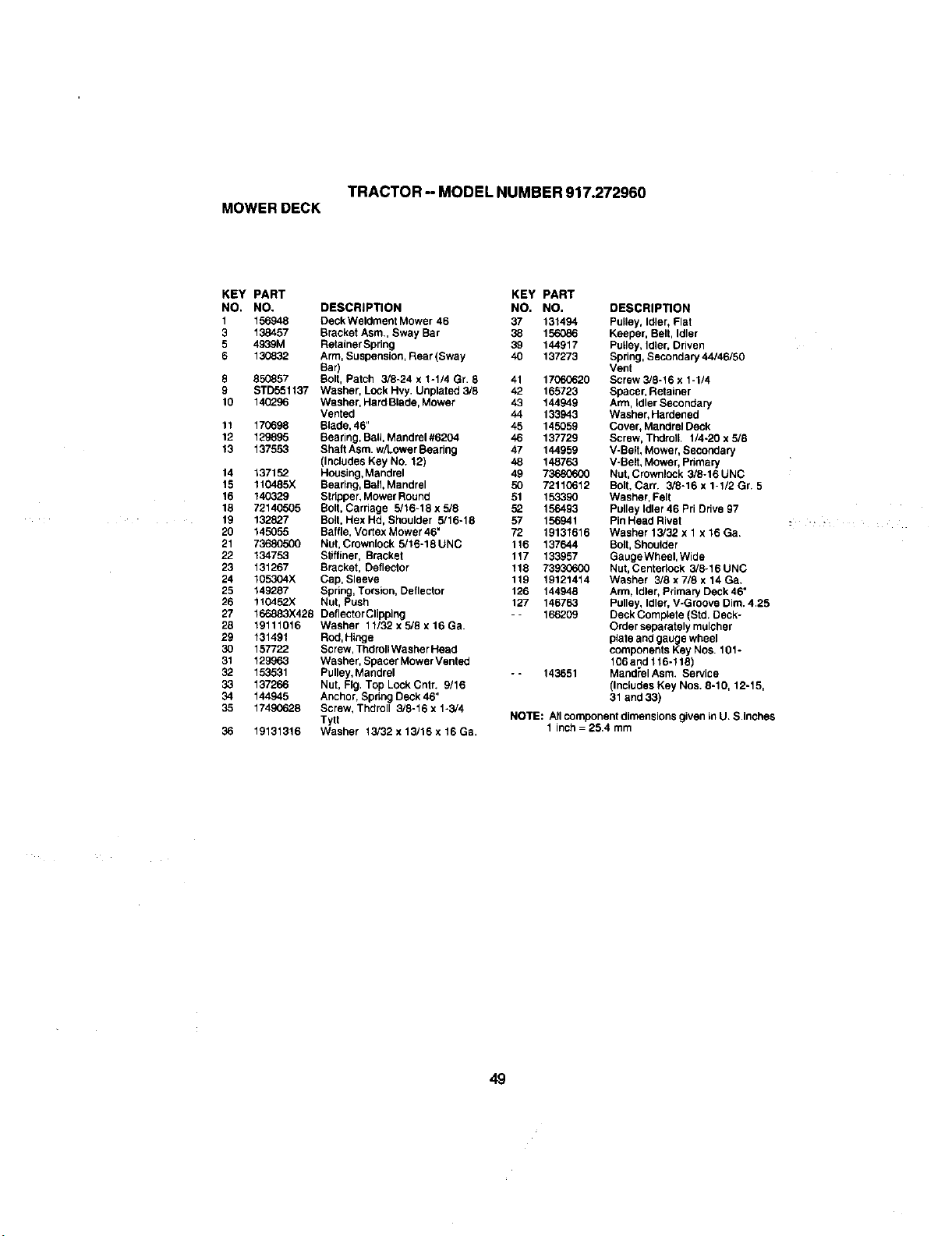
TRACTOR- MODEL NUMBER 917.272960
MOWER DECK
KEY
NO.
1
3
5
6
8
9
10
11
12
13
14
15
16
18
19
2O
21
22
23
24
25
26
27
28
29
30
31
32
33
34
35
36
PART KEY PART
NO. DESCRIPTION NO. NO. DESCRIPTION
156948 DeckWeldment Mower 46 37 131494 Pulley, Idler, Flat
138457 Bracket Asm,, Sway Bar 38 156086 Keeper, Belt, Idler
4939M Retainer Spring 39 144917 Pufley, Idler, Driven
130832 Arm, Suspension, Rear (Sway 40 137273 Spring, Secondary 44/46/50
Bar) Vent
850857 Bolt, Patch 3/8-24 x I-1/4 Gr. 6 41 17060620 Screw 3/8-16 x 1-1/4
STD551137 Washer, Lock Hvy. Unplated 3/8 42 165723 Spacer, Retainer
140296 Washer, Hard Blade, Mower 43 144949 Arm, Idler Secondary
Vented 44 133943 Washer, Hardened
170698 Blade, 46" 45 145059 Cover, Mandrel Deck
129895 Bearing, Ball, Mandrel #6204 46 137729 Screw, ThdrolL 1/4-20 x 5/8
137553 Shaft Asm. w/Lower Bearing 47 144959 V-Belt, Mower, Secondary
(Includes Key No. 12) 48 148763 V-Belt, Mower, Pdmary
137152 Housing, Mandrel 49 73680600 Nut, Crownlock 3/8-16 UNC
110485X Beadng, Ball Mandrel 50 72110612 Bolt. Cart. 3/8-16 x 1-1/2 Gr. 5
140329 Stdpper, Mower Round 51 153390 Washer, Felt
72140505 Bolt, Carhage 5/16-18 x 5/8 52 156493 Pulley Idler 46 Pri Drive 97
132827 Bolt, Hex Hd, Shoulder 5/16-18 57 156941 Pin Head Rivet
145055 Baffle, Vodex Mower 46" 72 19131616 Washer 13/32 x 1 x 16 Ga,
73680500 Nut, Crownlock 5/16-18 UNC 116 137644 Bod, Shoulder
134753 Stiffiner, Bracket 117 133957 GangeWheel, Wide
131267 Bracket, Deflector 118 73930600 Nut, Centerlock 3/8-t6UNC
I05304X Cap. Sleeve 119 19121414 Washer 3/Sx7/Sx14Ga.
149287 Spring, Torsion, Deflector 126 144948 Arm, Idler, Primary Deck 46"
110452X Nut, Push 127 146763 Pulley, Idler, V-Groove Dim. 4.25
166883X428 Deflector Clipping -- 166209 Deck Complete (Std. Deck-
19111016 Washer 11/32 x 5/8 x 16 Ga. Order separately mulcher
131491 Rod, Hinge plate and gauge wheel
157722 Screw, Thdroll Washer Head components Key Nos. 101 -
129963 Washer, Spacer Mower Vented 106and 116-118)
153531 Pulley, Mandrel -- 143651 Mandrel Asm. Service
137266 Nut, Fig. Top Lock Cntr. 9/16 (Includes Key Nos. 8-10, 12-t 5,
144945 Anchor. Spring Deck 46" 31 and 33)
1742O628 Screw, Thdroll 3/8-16 x 1-3/4
Tytt NOTE: Allcomponent dimensions given in U. S.Inches
19131316 Washer 13/32x 13/16x 16Ga. 1 inch=25.4 mm
49
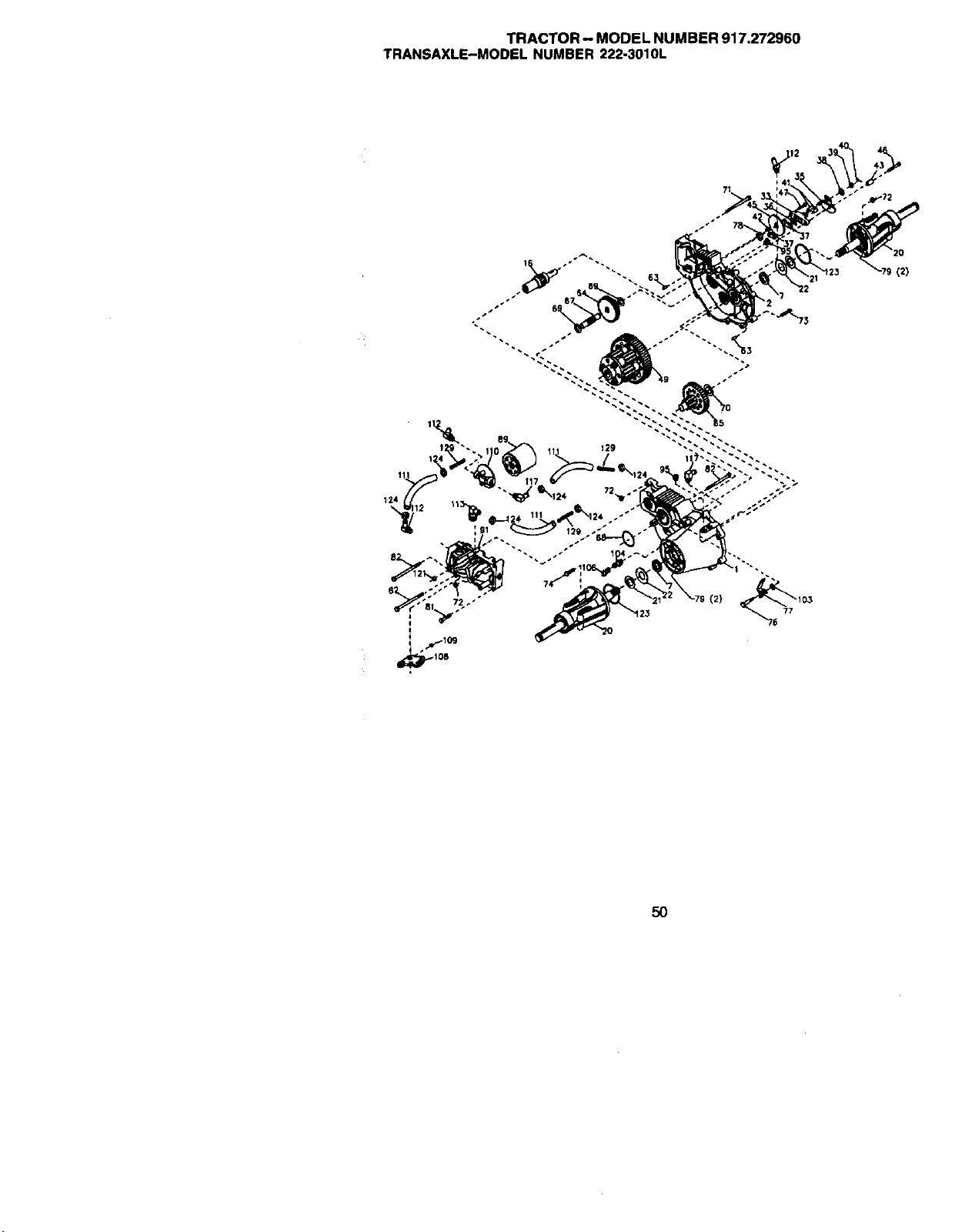
TRACTOR - MODEL NUMBER 917.272960
TRANSAXLE-MODEL NUMBER 222-3010L
(2)
(2)
5O
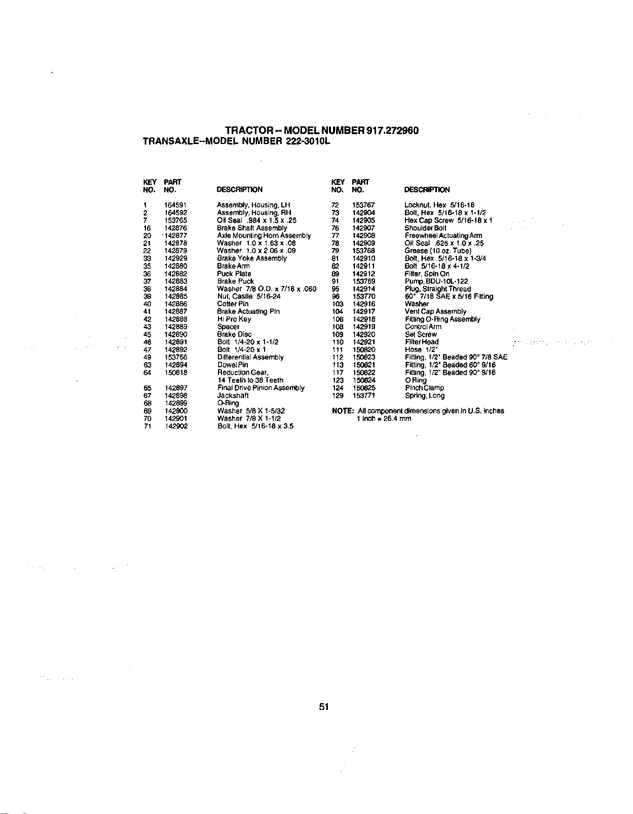
TRACTOR- MODEL NUMBER 917.272960
TRANSAXLE--MODEL NUMBER 222-3010L
K]EY pART _ pART
NO. NO. DESCRIPTION NO. NO, DESCRIPTION
1
2
7
16
2O
21
22
33
35
36
37
38
39
4O
41
42
43
45
46
47
49
63
64
65
67
68
69
70
71
164591 Assembly, Housing, LH 72 153767
164592 Assembly, Housing, RH 73 142SO4
153765 O11Seal ,984 x 1.5 x ,25 74 142905
142876 Brake Shaft Assembly 76 142907
-142877 Axle Mounting Horn Assenlbly 77 142908
142878 Washer 1.0 x 1,63 x .08 78 142909
142879 Washer 1.0 x 2.06 x .09 79 153768
142929 Brake Yoke Assembly 81 142910
142880 BrakeArm 82 142911
142882 Puck Plate 89 142912
142883 Brake Puck 91 153769
142884 Washer 7/80.D. x 7/16 x .060 95 142914
142885 Nut, Castle 5/16-24 96 153770
142886 Cotter Pin 103 142916
142887 Brake Actuating Pin 104 142917
142888 Hi Pro Key 106 142918
142889 Spacer 108 142919
142890 Brake Disc 109 142920
142891 Bolt 1/4-20 x 1-1/2 110 142921
142892 Bolt 1/4-20 x 1 111 150820
153766 Ditterential Assernbly 112 150823
142894 Dowbl Pin 113 150821
150818 Reduction Gear, 117 150822
14 Teethto 38 Teeth 123 150824
142897 Final Drive Pinion Assembly 124 150825
142898 Jackshatt
142899 O-Ring
142900 Washer 5/8 X 1-5/32
142901 Washer 7/8 X 1-1/2
142902 Bolt, Hex 5/16-18 x 3.5
LOCknut,Hex 5/16-18
Bolt, Hex 5/16-18 x 1-1/2
Hex Cap Screw 5/16-18 x t
Shoulder BOlt
Freewheel Actuating Arm
Oil Seal .625 x 1.0 x .25
Grease (10 oz. Tube)
Bolt, Hex 5/16-18 x 1-3/4
_blt 5/16-18 x 4-1/2
Filter, Spin On
Pump, BDU-10L-122
Plug, Straight Thread
60 ° 7/18 SAE x 5/16 Fitting
Washer
Vent Cap Assembly
Fitting O-Ring Assembly
ContrblArm
Set Screw
FiJterHead
Hose 1/2"
Fitting, 1/2' Beaded 90 ° 7/8 SAE
Fitting, 1/2' Beaded 60 ° 9/16
FiBing, 1/2" Beaded 90 ° 9/16
O Ring
Pinch Clamp
129 153771 Spring, Long
NOTE: All component dimensions given in U,S. inches
1 inch = 25.4 mm
51
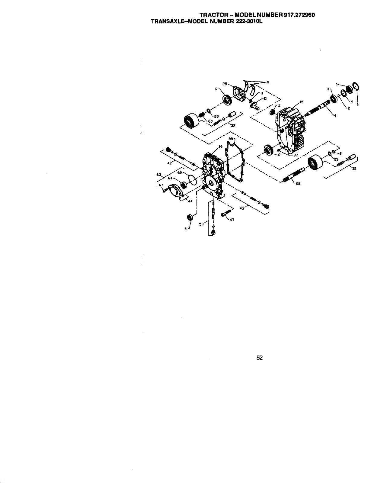
TRACTOR- MODEL NUMBER 917.272960
TRANSAXLE-MODEL NUMBER 222-3010L
52
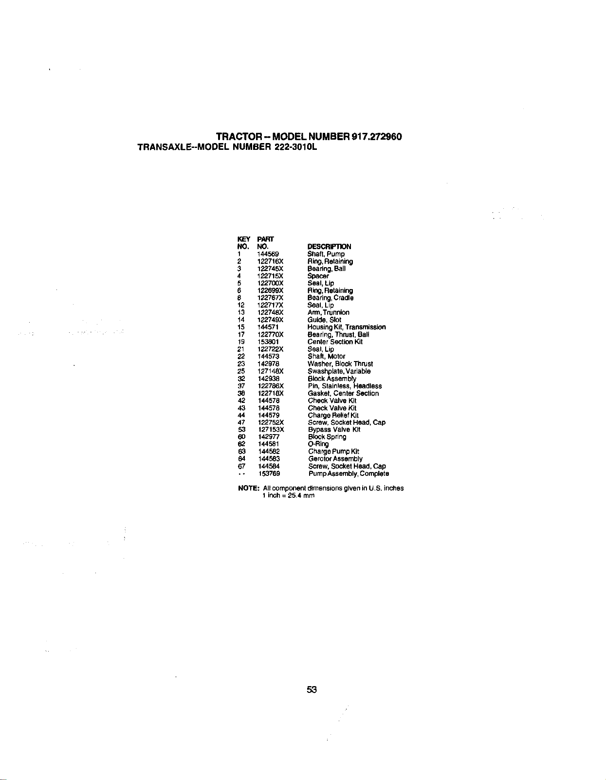
TRACTOR- MODELNUMBER917.272960
TRANSAXLE--MODELNUMBER222-3010L
KEY pART
NO. NO. DESCRIP1X)N
1 144569 Shaft, Pump
2 122716X Ring, Retaining
3 122745)( Bearing, Ball
4 122715)( Spacer
5 122700X Seal, Lip
6 122699X Ring, Retaining
8 122767X Rearing, Cradle
12 122717X Seal, Lip
13 122748X Arm,Trunnion
14 122749X Guide, Slot
15 144571 Housing Kit, Transmission
17 122770X Rearing, Thrust, Rail
19 153801 Center Section Kit
21 122722X Seal, Lip
22 144573 Shaft, Motor
23 142978 Washer, Block Thrust
25 127148)( Swashplate, Variable
32 142938 Block Assembly
37 122786X Pin, Stainless, Headless
38 122718X Gasket, Center Section
42 144578 Check Valve Kit
43 144578 Check Valve Kit
44 144579 Charge Relief Kit
47 122752X Screw, Socket Head, Cap
53 127153X Bypass Valve Kit
60 142977 Block Spdng
62 144581 O-Ring
63 144582 Charge Pump Kit
64 144583 Gerotor Assembly
67 144584 Screw, Socket Head, Cap
- - 153769 Pump Assembly, Complete
NOTE: All component dimensions given in U.S. inches
1 inch = 25.4 mm
53
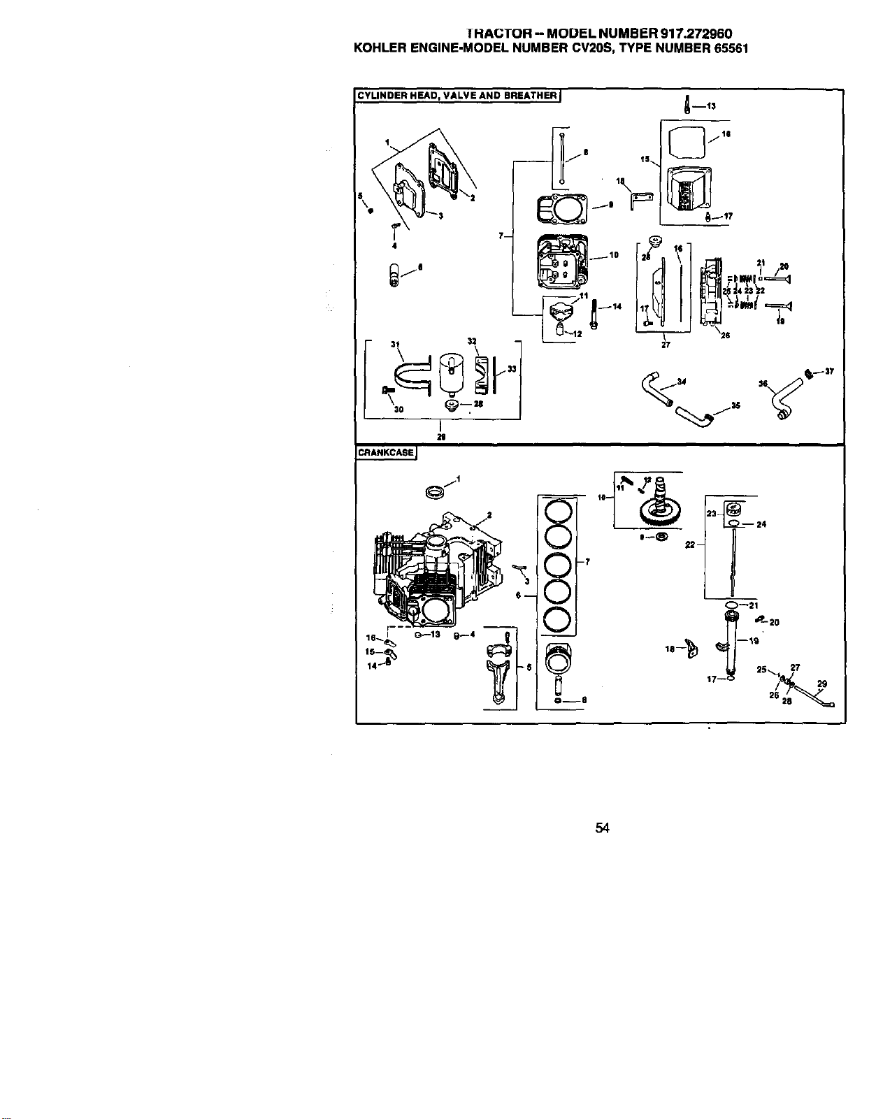
1HACTOR -- MODEL NUMBER 917,272960
KOHLER ENGINE-MODEL NUMBER CV20S, TYPE NUMBER 65561
CYLINDER HEAD, VALVE AND BREATHER I
\
4
7m
i
29
CRANKCAEEJ
54
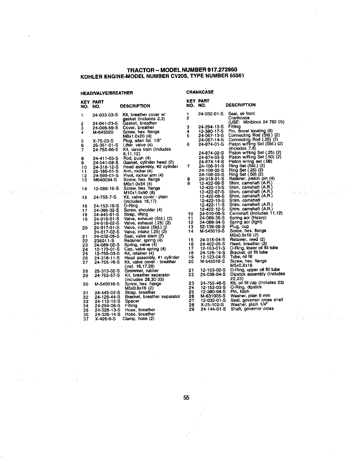
TRACTOR - MODEL NUMBER 917,272960
KOHLER ENGINE-MODEL NUMBER CV20S, TYPE NUMBER 65561
HEADNALVE/BREATHER
CRANKCASE
KEY PART KEY PART
NO. NO. DESCRIPTION NO. NO. DESCRIPTION
1 24-033-03-S Kit, breather cover w/ 1 24-032-01-S
gasket (Includes 2,3) 2
2 24-041-23-S Gasket, breather
3 24-096-59-S Cover, breather 3 24-294-13-S
4 M-645020 Screw, bex. flange 4 12-380-17-S
M6xl.0x20 (4) 5 24-067-13-S
5 X-75-23-S Plug, allen hd. 1/8" 24-067-t4-S
6 25-351-01-S Lifter, valve (4) 6 24-874-01-S
7 24-755-66-S Kit, valve train (Includes
6,11,12) 24-874-02-S
8 24-411-05-S Rod push 4 24-874-03-S
9 24-041-08-S Gasket, cylinder head 2 24-874_14-S
10 24-318-12-S Head assembly, #2 cylinder 7 24-108-01-S
11 25-186-01-S Arm, rocker (4) 24-108-02-S
12 24-599-O1-S Pivot, rocker arm (4) 24-t08-O3-S
13 M640034-S Screw, hex. flange 8 24-018-01-S
M6x1.0x34 (4) 9 12-422-09-S
14 12-086-16-S Screw, hex. flange 12-422-13-S
M10x1.5x00 (8) 12-422-07-S
15 24-755-7-S Kit, valve cover - plain 12-422-08-S
(Includes 16,17) 12-422-10-S
16 24-153_16-S O-Ring 12-422-11-S
17 24-086-32-S Screw, shoulder (4) 12-422-12-S
18 24-445-01-S Strap, lifting 10 24-010-06-S
19 24-O16-01-S Valve, exhaust (Std.) (2) 11 24-089-35-S
24-016-02-S Valve, exhaust (.25) (2) 12 24-089-34-S
20 24-017-01-S Valve, intake Std.) (2 13 52-139-09-S
24-017-02-S Valve, intake (.25) (2) 14 M-545010-S
21 24-032-05-S Seal, valve stem (2)
22 235011-S Retainer, spring (4) 15 24.018-04-S
23 24-089-02-S Spring, valve (4) 16 24-402-05-S
24 12-173-01-S Cap, valve spring 4) 17 12-153-01-S
25 12-755-03-S Kit, retainer (4) 18 24-126-19-S
26 24-318-11-S Head assembly, #1 cylinder 19 12-123-04-S
27 24-755-76-S Kit, valve cover - breather 20 M-545016-S
_lnch 16,17,26)
28 25-313-02-S Grommet, rubber 21 12-153-02-S
29 24-755-57-S Kit, breather separator 22 24-038-04-S
(Includes 28,30-33)
30 M-545016-S Screw, bex. flange 23 24-755-46-S
M5xO.8x16 (2) 24 12-153-03-S
31 24-445-02-S Strap, breather 25 12-380-04-S
32 24-126-44-S Bracket, breather separator 26 M-631005-S
33 24-112-12-S Spacer 27 12-032-01-S
34 24-294-06-S Fitting 28 X-25-102-S
35 24-326-13-S Hose, breather 29 24-144-01-S
36 24-326-14-S Hone, breather
37 X-426-9-S Clamp, hose (2)
Seal, oil front
Crankcase
_USE: Miniblcck 24 782 05)
Fittin
q
Pin, dowel locating (6)
Connecting Rod Std.) (2)
Connecting Rod (.25) (2)
Piston w/Ring Set (Std.) (2)
(Includes 7,8)
Piston wiRing Set (,25) (2)
Piston wiring Set (.50) 2)
Piston wiring set (.(38)
Ring Set (Std.) (2)
Ring Set (.25) (2)
Ring Set (.50) 2
Retainer, piston pin (4)
Shim, camshaft (A.R.)
Shim, camshaft (A.R.)
Shim, camshaft A.R.)
Shim, camshaft A.R.
Shim, camshaft
Shim, camshaft (A.R.
Shim, camshaft A.R.
Camshaft (Includes 11,12)
Spring acr Heavy)
Spring acr (light)
Plug, cup
Screw, hex. flange
M5x0.8xl0 (2)
Retainer, reed (2)
Reed, breather (2)
O-Ring, lower oil fdl tube
Bracket, oil fill tube
Tube, oil fill
Screw, hex. flange
M5xO.8x16
O-Ring, upper oil fill tube
Dipstick assembly (Includes
22,23)
Kit, oil fill cap (Includes 23)
O-Rin_, dipstick
Pin, h_tch
Washer, plain 6 mm
Seal, governor cross shaft
Washer, plain 1/4"
Shaft, governor cross
55
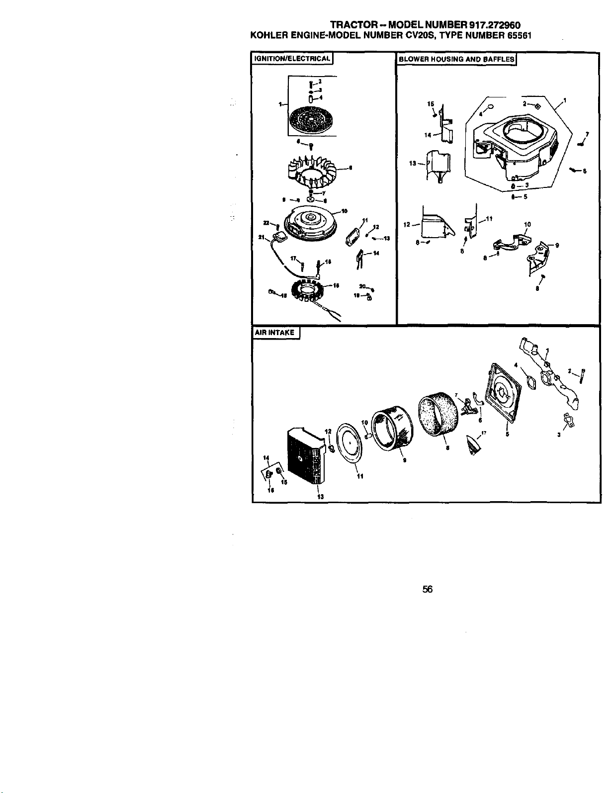
TRACTOR- MODELNUMBER917.272960
KOHLERENGINE-MODELNUMBERCV20S,TYPENUMBER65561
IGNITION/ELECTRICAL I
_'T
=_) _'° /Ij2
AIR INTAKE J
BLOWER HOUSfNG AND BAFFLES I
3
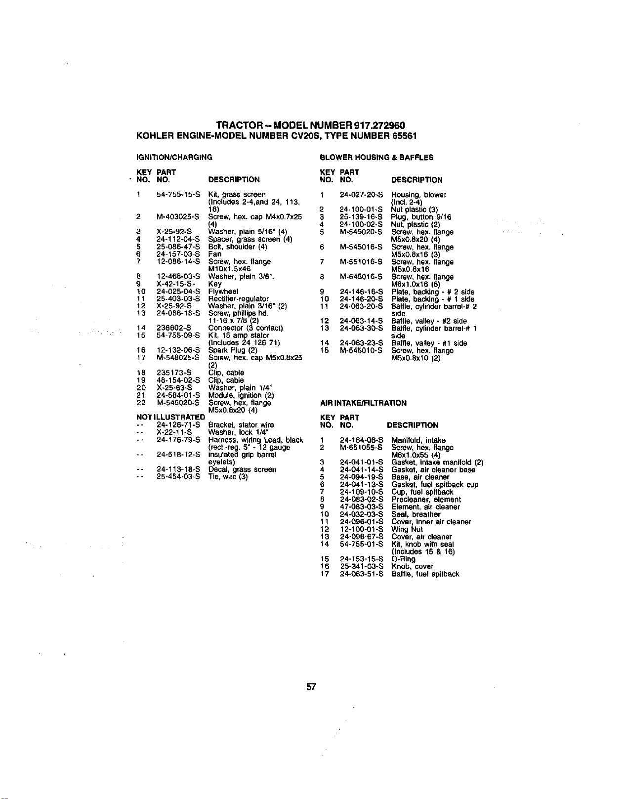
TRACTOR - MODEL NUMBER 917.272960
KOHLER ENGINE-MODEL NUMBER CV20S, TYPE NUMBER 65561
IGNITION/CHARGING BLOWER HOUSING & BAFFLES
KEY PART KEY PART
• NO. NO, DESCRIPTION NO. NO. DESCRIPTION
1 54-755-15-S Kit, grass screen t 24-027-20-S Housing, blower
(Includes 2-4,and 24, 113, (Incl. 2-4)
18) 2 24-100-01-S Nut plastic (3)
2 M-403025-S Screw, hex. cap M4x0.7x25 3 25-139-16-S Plug, button 9/16
_)a 4 24-100-02-S Nut, plastic (2)
3 X-25-92-S sher, plain 5/16" (4) 5 M-545020-S Screw, hex. flange
4 24-112-04-S Spacer, grass screen (4) M5xO,Bx20 (4)
5 25-086-47-S Bolt, shoulder (4) 6 M-545016_S Screw, hex. flange
6 24-157-03-S Fan M5x0,8x16 (3)
7 12-086-14-S Screw, hex. flange 7 M-551016-S Screw, hax. flange
Ml0x1.5x46 M5x0.8x16
8 12-468-03/S Washer, plain 3/8". 8 M-645016-S Screw, hax. flange
g X-42-15-S- Key M6x1.0xt6 6)
10 24-025-04-S Flywheel 9 24-146-16-S Plate, backing - # 2 side
11 25-403-03-S Rectifier-regulator 10 24-146-20-S Plata, backing - # 1 side
24-063-20-S Baffle, cylinderbarrel-# 212 X-25-92-S Washer, plain 3/16" (2) 11
13 24-086-18-S Screw, phillips hd. side
11-16 x 7/5 (2) 12 24-063-14-S Baffle, valley - #2 side
14 236602-S Connector (3 contact) 13 24-063-30-S Baffle, cylinder barrel-# 1
15 54-755-09-S Kit, 15 am_pstator side
(Includes 24 126 71) 14 24-063-23-S Baffle, valley - #1 side
16 12-132-06-S Spark Plug (2) 15 M-545010-S Screw, hex. flange
17 M-548025-S Screw, hex. cap M5x0.8x25 M5x0.Sxl0 (2)
(2)
18 235173-S Clip, cable
19 48-154-02-S Clip, cable
20 X-25-63-S Washer, plain 1/4"
21 24-584-01-S Module, ignition (2)
22 M-545020-S Screw, hex. flange AIR INTAKE/FILTRATION
M5x0.8x20 (4)
NOT ILLUSTRATED
-- 24-126-71-S Bracket, stator wire
-- X-22-11-S Washer, lock 1/4"
-- 24-176-79-S Harness, wiring Lead, black
(rect.-reg. 5" o 12 gauge
-- 24-518-12-S iasulated grip barrel
eyelets)
*- 24-113-18-S Decal, grass screen
-- 25-454-03-S Tie, wire (3)
KEY PART
NO. NO. DESCRIPTION
1 24-164-06-S Manifold, intake
2 M-651055-S Screw, hex. flange
M6x1.0x55 (4)
3 24-041-0t-S Gasket, intake manifold (2)
4 24-041-14-S Gasket, air cleaner base
5 24-094-19-S Base, air cleaner
6 24-041-13-S Gasket, fuel spitback cup
7 24-109-10-S Cup, fuel spgback
8 24-083-02-S Preclaaner, element
9 47-083-03-S Element, air cleaner
10 24-032-03-S Seal, breather
11 24-096-01-S Cover, inner air cleaner
12 12-100-01-B Wing Nut
13 24-096-67-S Cover, air cleaner
14 54-755-01-B Kit, knob with seal
(includes 15 & 16)
15 24-153-15-S O-Ring
16 25-341-03-S Knob, cover
17 24-063-51-S Baffle, fuel spitback
57
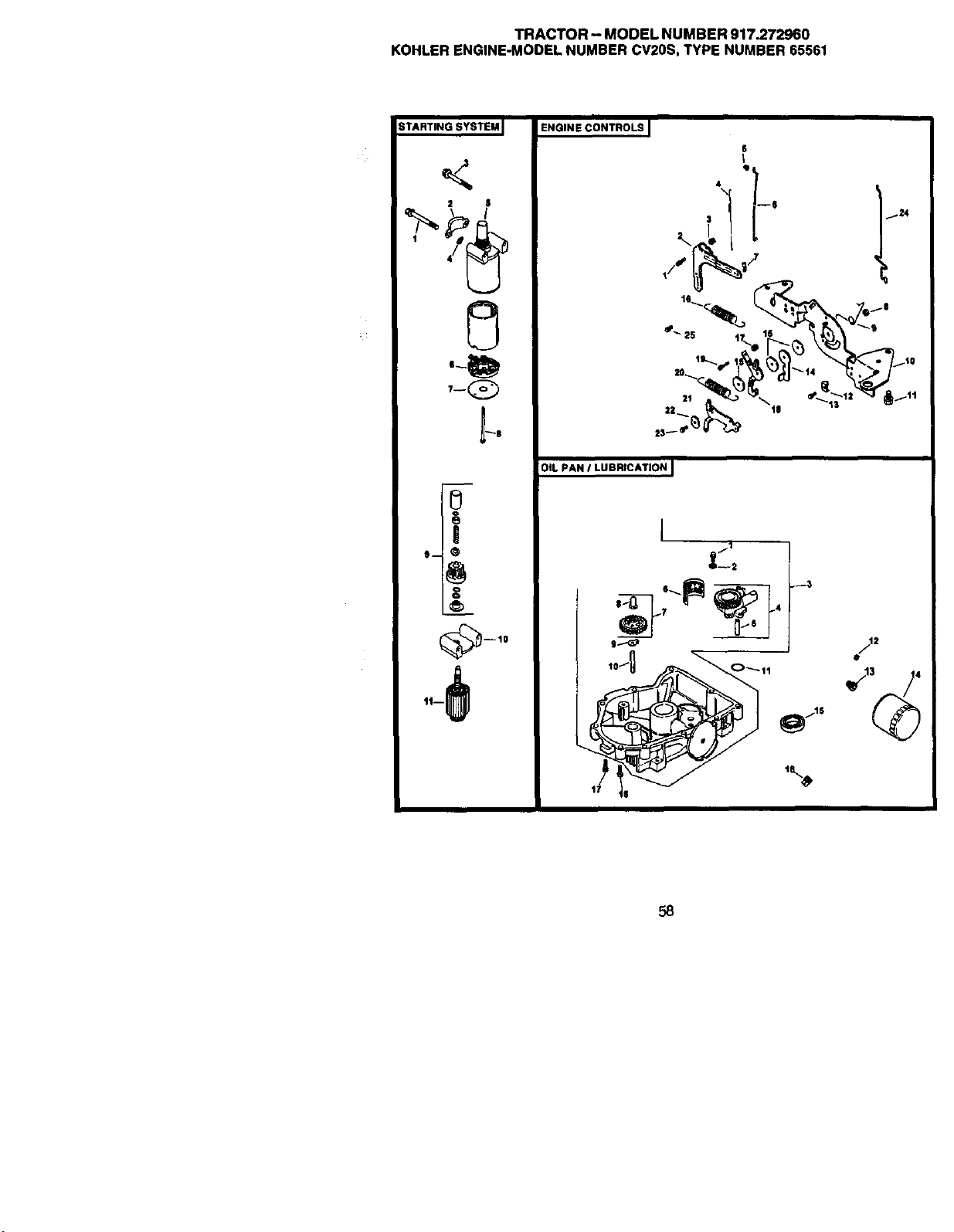
TRACTOR- MODELNUMBER917.272960
KOHLERENGINE-MODELNUMBERCV20S,TYPENUMBER65561
STARTING SYSTEM I
2 S
!
I)-- _)
ENGINE CONTROLS
S
Q
r
4 q
16 • _'$
OIL PAN / LUBRICATION I
J
/1
$..-_ J /2
%
I;' $
58
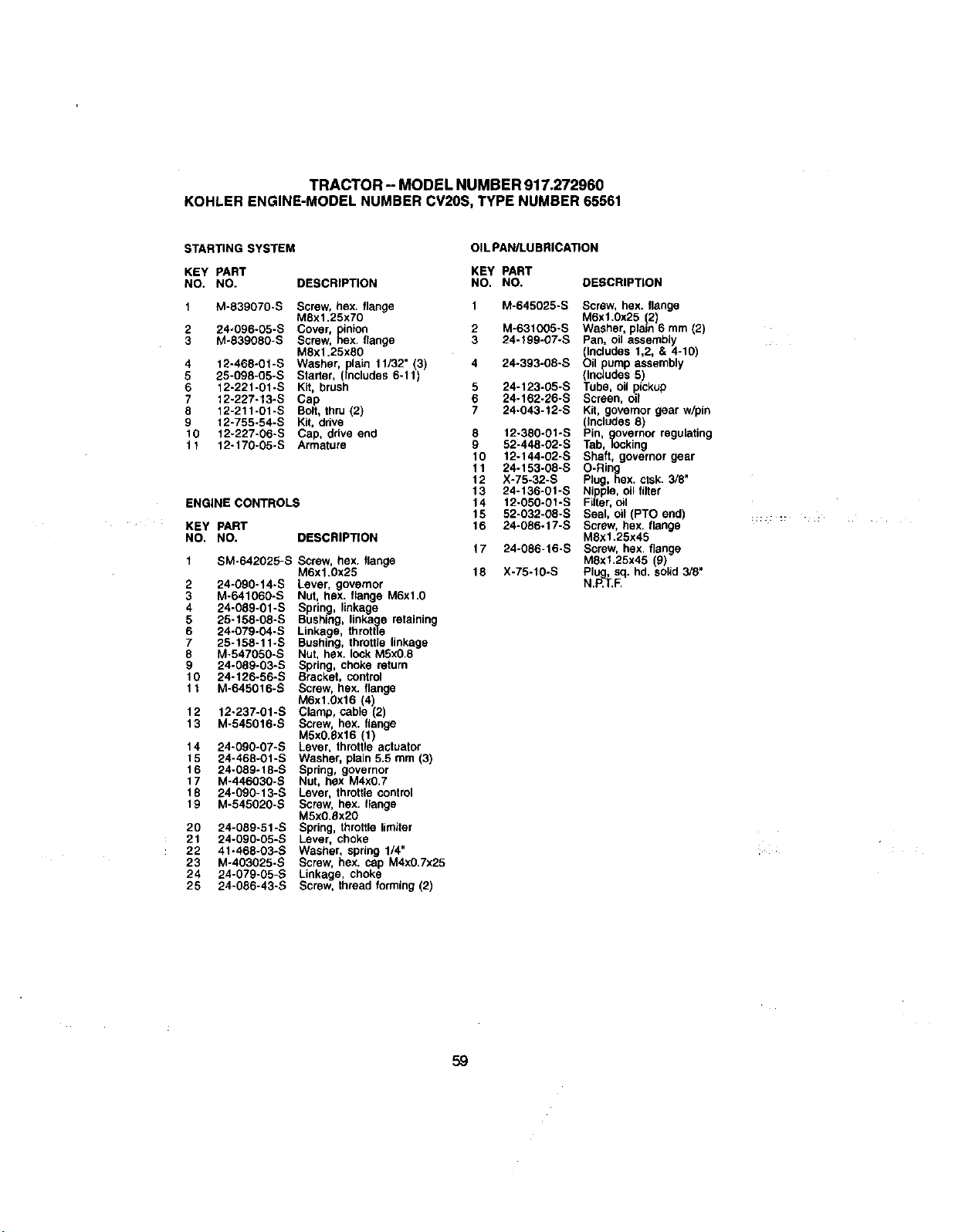
TRACTOR -- MODEL NUMBER 917.272960
KOHLER ENGINE-MODEL NUMBER CV20S, TYPE NUMBER 65561
STARTING SYSTEM
KEY PART
NO. NO.
"_ M-839070-$
2 24-O96-05-S
3 M-839080-S
4 12-468-01-S
5 25-098-05-S
6 12-221-01-S
7 12-227-13-S
8 12-211-01-S
9 12-755-54-S
10 12-227-06-S
11 12-170-05-S
OIL PAN/LUBRICATION
KEY PART
DESCRIPTION NO. NO. DESCRIPTION
ENGINE CONTROLS
KEY pART
NO. NO.
I SM-642025-S
2 24-090-14-S
3 M-641060-S
4 24-089-01-S
5 25-158-08-S
6 24-079-04-S
7 25-158-11-S
8 M-547050-S
24-089-03-S
0 24-126-56-S
11 M-645016-S
12 12-237-01-S
13 M-545016-S
4 24-090-07-S
15 24-468-01-S
16 24-089-18-S
17 M-446030-S
18 24-090-13-S
t 9 M-545020-S
20 24-089-51-S
21 24-090-05-S
22 41-468-03-S
23 M-403025-S
24 24-079-05-_
25 24-086-43-S
Screw, hex. flange
M8x1.25x70
Cover, inion
Screw, _ex. flange
MSxt .25x80
Washer, plain 11/32" (3)
Starter, (includes 6-11)
Kit, brush
Cap
Bolt, tllru (2)
Kit, drive
Cap, drive end
Armature
DESCRIPTION
Screw, hex. flange
M6x1.0x25
Lever, governor
Nut, hex. flange M6xl.0
Spring, linkage
Bushing, linkage retatning
Linkage, throttle
Bushing, throttle linkage
Nut, hex. lock MSx0.8
Spring, choke return
Bracket, control
Screw, hex. flange
M6xl.0x16 (4
Clamp cable 2
Screw, hex. flange
M5x0.Sx16 (1)
Lever, throttle actuator
Washer, plain 5.5 mm (3)
Spring, governor
Nut, hex M4x0.7
Lever thro_ttecontrol
Screw, hex. lange
M5x0.Sx20
Spring, throttle limiter
Lever, choke
Washer, spring 1/4"
Screw, hex. cap M4x0,7x25
Linkage, choke
Screw, thread forming (2)
1 M-645025-S Screw, hex. flange
M6xt .0x25 (2)
2 M-631005-S Washer, plain 6 mm (2)
3 24-199-07-S Pan, oil assembly
(Includes 1,2, & 4-10)
4 24-393-08-S Oil pump assembly
(Includes 5)
5 24-123-05-S Tube, oil pickup
6 24-162-26-S Screen, oil
7 24-043-12-S Kit, governor gear w/pin
(Includes 0)
8 12-380-01-S Pin, go_overnorregulating
9 52-448-02-S Tab, k;c,king
10 12-144-02-S Shaft, governor gear
11 24-153-08-S O-Ring
12 X-75-32.S Plug, hex. ctsk. 3/8"
13 24-136-01-S Nipple, oi_titter
14 12-050-01-S Filter, oil
t 5 52-032-08-S Seal, oil (PTO end) ......
16 24-086.17-S Screw, hex. flange
M8xt.25x45
17 24-086-16-S Screw, hex. flange
MSx1,25x45 (g)
18 X-75-10-S Plug, sq. hd. solid 3/8"
N.P,T.F.
59
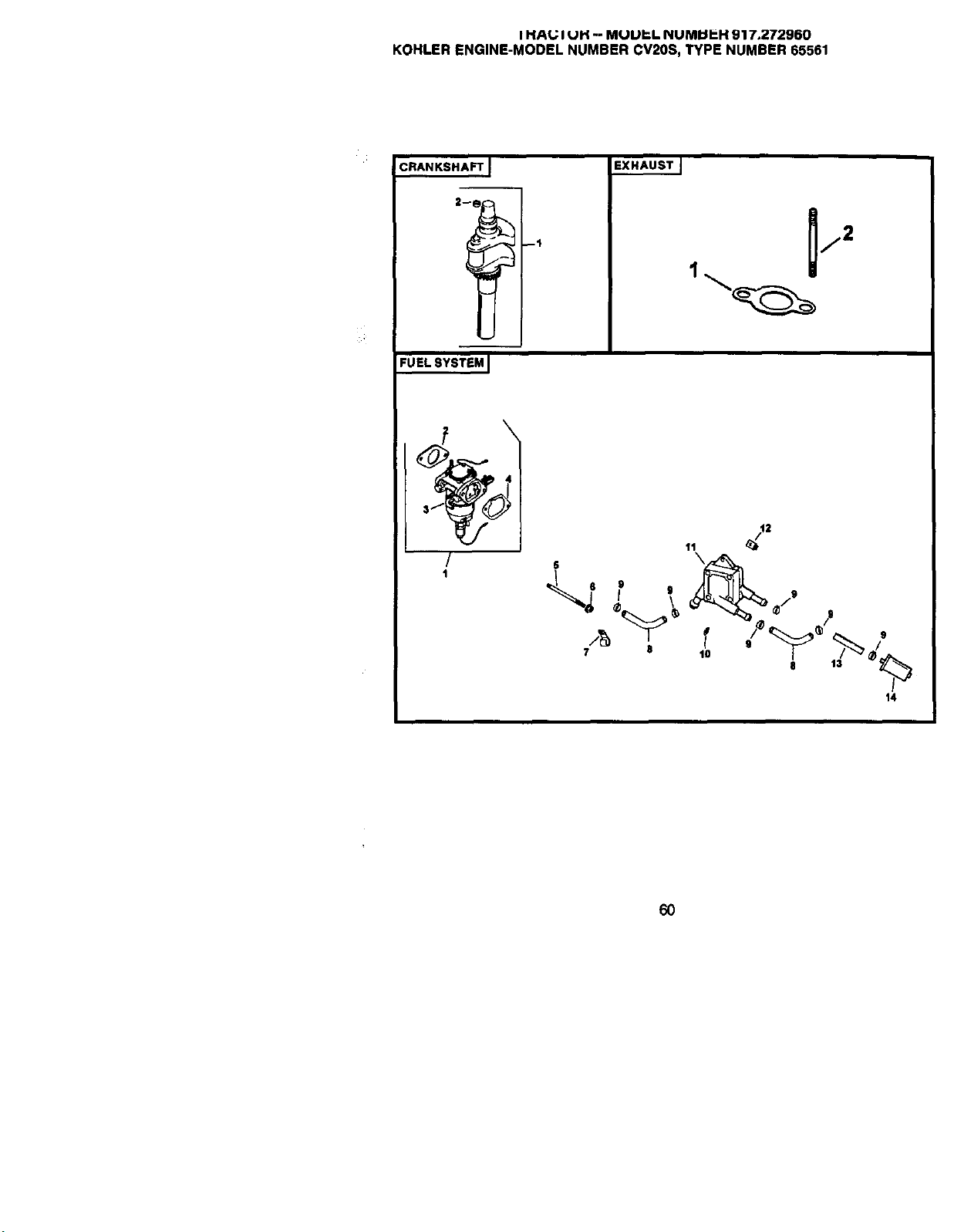
I HAU I UH -- MUUP.L NUMUP-H 917,272960
KOHLER ENGINE-MODEL NUMBER CV20S, TYPE NUMBER 65561
CRANKSHAFT [
EXHAUSTJ
j2
1
FUELSYSTEM I
i
/
1
iv
14
60
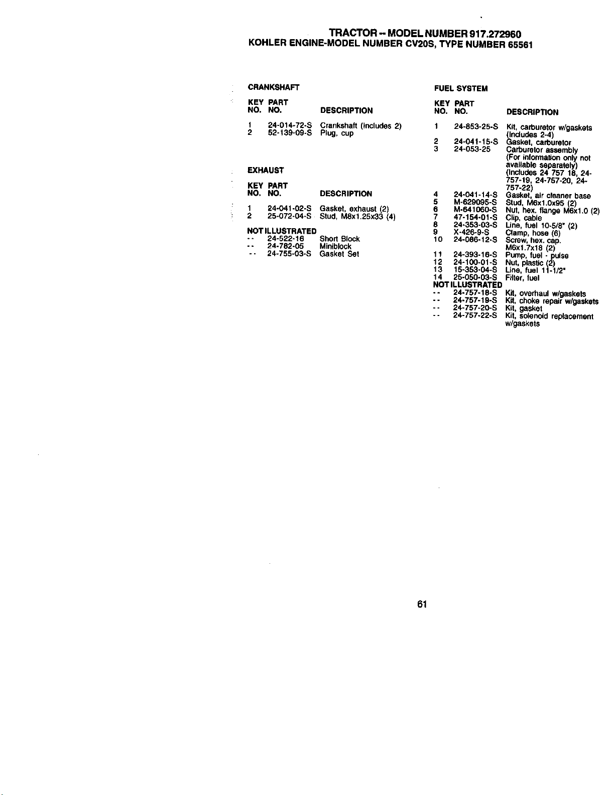
TRACTOR - MODEL NUMBER 917.272960
KOHLER ENGiNE-MODEL NUMBER CV20S, TYPE NUMBER 65561
CRANKSHAFT FUEL SYSTEM
KEY PART KEY PART
NO. NO. DESCRIPTION NO. NO.
1 24-014-72-S Crankshaft (Includes 2) 1 24-853-25-S
2 52-139-09-S Plug, cup
2 24-041-15-S
3 24-053-25
EXHAUST
KEY PART
NO, NO. DESCRIPTION
1 24-041-02-S Gasket exhaust (2)
2 25-072-04-S Stud, M8xl.25x33 (4
NOTILLUSTRATED
.- 24-522-16 Shod Block
-- 24-782-05 Minib$ock
-- 24-755-03-S Gasket Set
4 24-041-t4-S
5 M-629095-S
6 M-641060-S
7 47-154-01-S
8 24-353-03-S
9 X-426-9-S
10 24-086-12-S
11 24-393-16-S
12 24-100-01-S
13 15-353-04-S
14 25-050-03-S
NOTILLUSTRATED
-- 24-757-18-S
-- 24-757-19-S
-- 24-757-20-S
-- 24-757-22-S
DESCRIP'nON
Kit, carburetor w/gask_
_ncludes 2-4)
asket, carburetor
Carburetor assembly
(For _,tormation on$¥r
avaUablo separately)
(Includes 24 757 18, ;
757-19, 24-757-20, 2_
757-22)
Gasket, air cleaner ba
Stud, M6x1,0x95 (2)
Nut, hex. flange M6xt
Clip, cable
Line, fuel 10-5/9" (2)
Clamp, hose (6)
Screw, hex. cap.
M6xl.7x18 (2
Pump, fuel -pulse
Nut, plastic (2)
Line, fuel 1t-1/2 =
Filter, fuel
Kit, overhaul w/gasket:
Kit, choke repair w/ga_
Kit, gasket
Kit, solenoid rep(acem
w/gaskets
61

62
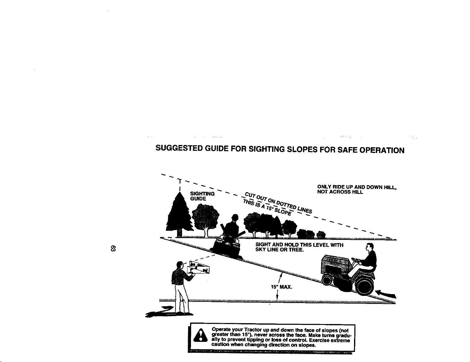
SUGGESTED GUIDE FOR SIGHTING SLOPES FOR SAFE OPERATION
SIGHTING "_
GUIDE
ONLY RIDE UP AND DOWN HILL,
NOT ACROSS HILL
I_ erate your Tractor up and down the face of slopes (not i
greater than 15°) never across the face. Make rums gredu-
I
ally to prevent tipping or loss of control. Exerc se extreme
caution when changing direction on slopes.

Get it fixed, at your home or ours!
For repair of major brand appliances In your own home,,,
no matter who made it, no matter who soldit!
1-800-4-MY-HOME SMAoytir.e.dayor night
(1-800-469-4663)
www.sears.com
To bring in products such as vacuums,
lawn equipment and electronics for repair, call for
the location of your nearest Sears Parts & Repair Center.
1-800-488-1222 Anytime,day ornight
www.sears.com
Forthe replacement parts, accessories and owner's manuals
that you need to do-it-yourself, call Sears PartsDirectSM!
1-800-366-PART 8am- 11p.m.CST,
(1-800-366-7278) 7 days a week
www.sears.com/partsdirect
To purchase or inquire about a Sears Service Agreement:
1-800-827-6655
7 a.rn.- 5 p.m.CST,Mon.- Sat.
Para pedlreervicio de reparact_)na domicilio, Au Canada pourserviceen frar_is:
y paraordenarpiezas con entrega a domicllio: 1-877-LE-FOYER _
1-888-SU-HOGAR s. (1-877-533-6937)
(1-888-784-6427)
SEARS ]
HomeCentral"
O Sears, Roebuck and Co.
® RegisteredTrademark/TM Trademarkof Sears, Roebuckand Co,
® Mama Registrada/ TMMarcade F_briCade Sears, Roebuckand Co.
172013 Rev. 4 06.27.00 RD/RH Printed in the U.S.A.


