
Loading ...
Loading ...
Loading ...
© FISHER & PAYKEL LIMITED 202 PAGE 459000269A PLANNING GUIDE MODULAR COOKTOPS VERSION 1 - AUGUST 202 © FISHER & PAYKEL LIMITED 202 PAGE 459000269A PLANNING GUIDE MODULAR COOKTOPS VERSION 1 - AUGUST 202
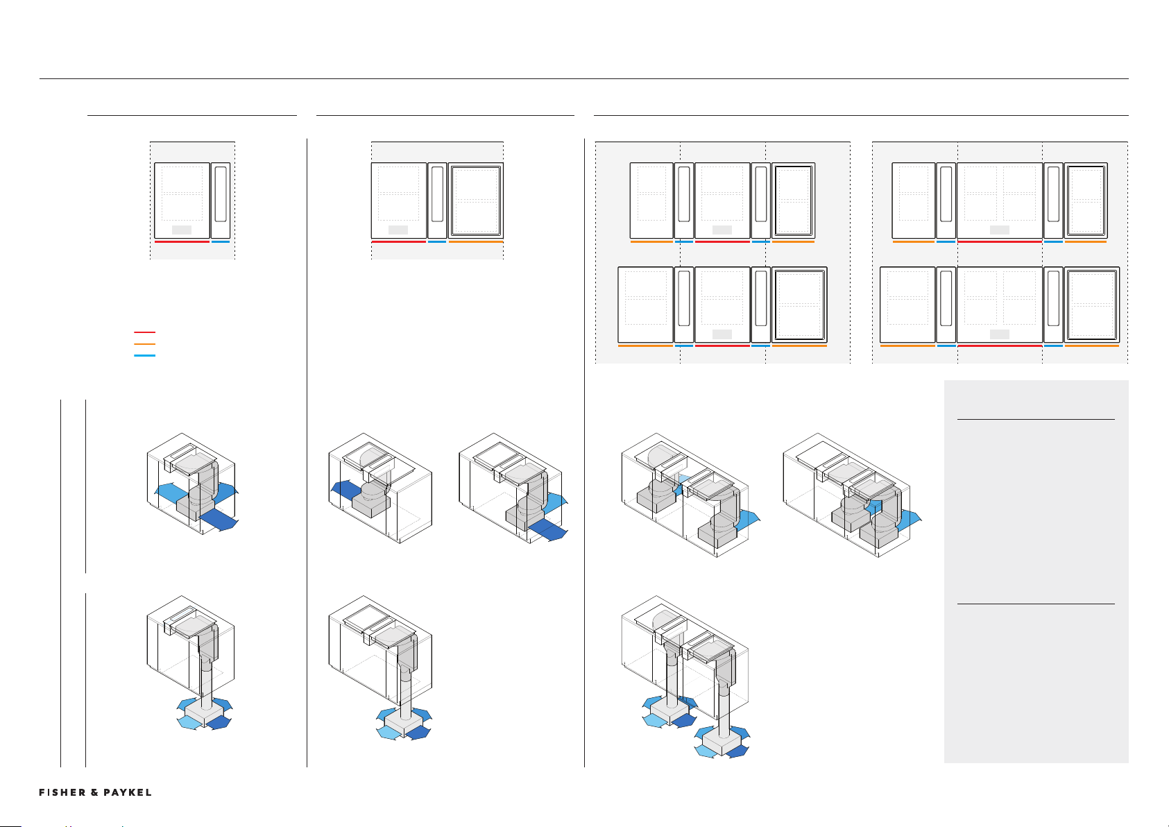
TYPICAL CONFIGURATIONS WITH MODULAR VENTILATION AND DUCTING
LAYOUTS APPLY TO BOTH A 9CM AND 60CM CENTRAL COOKTOP MODULE
9cm
600 600 600600 600 600
900
600
9cm9cm 0cm 9cm 0cm
9cm 9cm 9cm
0cm 60cm 0cm
9cm 60cm 9cm
SINGLE - COMPACT <600 TWO IN A ROW - MID <900 THREE IN A ROW - WIDE >1200
SPACE REQUIREMENTS
These are representational
illustrations of typical
configurations with modular
ventilation and ducting installed
in standardised cabinetry widths
to provide an overview of
cabinetry requirements. Other
configurations are possible.
IMPORTANT
A full assessment should be
undertaken of chosen modular
components within cabinetry
dimensions specific to location,
materials and construction
methods.
BLOWER PLACEMENT
SUB-FLOOR BLOWER BOX ON FLOOR BLOWER BOX
Ducting can also exit to left.
Ducting can also exit to left.
Ducting can also exit to left.
Configurations can not be mirrored. Layout determined due to
asssymetry of blower box.
Layout can be mirrored.
PRIMARY COOKTOP
AUXILIARY COOKTOP
AUXILIARY VENTILATION
Typical Cabinetry Configurations
PLANNING CONSIDERATIONS | MODULAR COOKTOPS
Loading ...
Loading ...
Loading ...