
PLANNING GUIDE
MODULAR COOKTOPS
CI392DTT CI604DTT CIDTT CI905DTT CID CI392D
CITDX CIT392DX1 | CD13D

© FISHER & PAYKEL LIMITED 202 PAGE 29000269A PLANNING GUIDE MODULAR COOKTOPS VERSION 1 - AUGUST 202
CI92DTT CI604DTT CIDTT CI905DTT CID CI92D CITDX CIT92DX1 | CD1DPLANNING GUIDE | MODULAR COOKTOPS
This comprehensive planning guide provides you with the framework and tools to achieve your desired design outcome with Fisher & Paykel appliances. In this guide, you will
find a range of conceptual, detailed, and dimensional product information to bring your ideas to life and create spaces that truly reflect your vision.
CONCEPT DESIGN PAGE DEVELOPED AND DETAILED DESIGN PAGE DEVELOPED AND DETAILED DESIGN PAGE
Specification Guide 3
System Overview 4
Primary Modules 6
Auxiliary Modules 7
Data Sheets 8
Primary Induction Cooktop, 9cm 9
Primary Induction Cooktop, 60cm 10
Primary Induction Cooktop, 76cm 11
Primary Induction Cooktop, 90cm 12
Auxiliary Induction Cooktop, 0cm 1
Auxiliary Teppanyaki Cooktop, 0cm 14
Auxiliary Induction Cooktop, 9cm 15
Auxiliary Teppanyaki Cooktop, 9cm 16
Auxiliary Ventilation Components 17
Mainbox 18
Blowerbox 19
Horizontal Elbow, 90
Vertical Elbow, 90
Duct Adapter, 90
Duct Adapter, 150mm Diameter 2
Connector 24
Straight Ducting 25
Recirculation Kit 26
Product Decisions 28
Pairing Guide 29
Modular System Capabilities 0
Modular Ventilation Capabilites 1
Ventilation Choice 2
Planning Considerations 33
Installation Overview 4
Combined Installation 5
Typical Configurations with Modular Ventilation 6
Typical Configurations with Overhead Ventilation 7
Benchtop Details 8
Cooktop Cooling Ventilation 40
Cabinetry Considerations 41
Modular Ventilation 42
Typical Cabinetry Configurations 45
Electrical Services 46
CONTENTS
CONTENTS

© FISHER & PAYKEL LIMITED 202 PAGE 9000269A PLANNING GUIDE MODULAR COOKTOPS - VERSION 1 - AUGUST 202
SPECIFICATION GUIDE
© FISHER & PAYKEL LIMITED 202 PAGE 49000269A PLANNING GUIDE MODULAR COOKTOPS VERSION 1 - AUGUST 202
SPECIFICATION GUIDE | MODULAR COOKTOPS
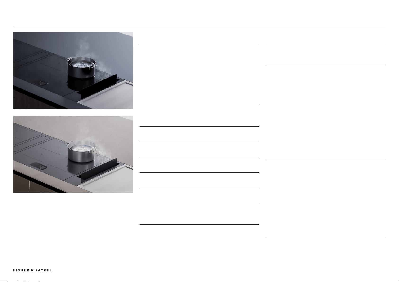
OVERVIEW
Create the ultimate culinary solution with our Series 9 and 11
modular cooktops. Using the dierent induction, teppan and
ventilation modules you can customise the cooking area, at the
scale and format best suited to architectural plan and user
needs. Fusing precise induction technology with innovative
design, these modules are crafted to seamlessly work together
for perfect results
FEATURES
1 Tailor the cooking space by pairing primary induction
cooktop modules with complementary auxiliary cooktops,
downdraft ventilation and teppan modules.
2 Control the complete modular suite from the primary cooktop
using a large intuitive touchscreen.
3 Each module is designed to fit flush or raised with the
countertop for complete design freedom.
4 Choose from a Minimal style sleek black glass or subtle grey
glass finish to suit your kitchen design.
5 SmartHQ™ app connectivity to monitor cook status and
product.
6 Wireless Temperature Sensor precisely monitors and controls
cooking in real time, for complete control.*
7 Poach, Sous Vide and other Cook by Method functions are
available on product, when using the Wireless Temperature
Sensor.
* Selected models only.
PRODUCT OVERVIEW
PRIMARY MODULAR INDUCTION COOKTOPS
With touchscreen
CI392DTTB1 (Black), CI392DTTG1 (Grey)
Primary Modular Induction Cooktop, 39cm, 2 Zones with
SmartZone
CI604DTTB1 (Black), CI604DTTG1 (Grey)
Primary Modular Induction Cooktop, 60cm, 4 Zones with
SmartZone
CI764DTTB1 (Black), CI764DTTG1 (Grey)
Primary Modular Induction Cooktop, 76cm, 4 Zones with
SmartZone
CI905DTTB1 (Black), CI905DTTG1 (Grey)
Primary Modular Induction Cooktop, 90cm, 5 Zones with
SmartZone
AUXILIARY MODULAR COOKTOPS
No touchscreen
CI302DB1 (Black), CI302DG1 (Grey)
Auxiliary Modular Induction Cooktop, 30cm, 2 Zones with
SmartZone
CI392DB1 (Black), CI392DG1 (Grey)
Auxiliary Modular Induction Cooktop, 39cm, 2 Zones with
SmartZone
CIT302DX1
Auxiliary Modular Teppanyaki Cooktop, 30cm, 2 Zones
CIT392DX1
Auxiliary Modular Teppanyaki Cooktop, 39cm, 2 Zones
AUXILIARY MODULAR VENTILATION - No touchscreen
CD13DB1 (Black), CD13DG1 (Grey)
Auxiliary Modular Ventilation, 13cm, Duct Out
System Overview

© FISHER & PAYKEL LIMITED 202 PAGE 59000269A PLANNING GUIDE MODULAR COOKTOPS VERSION 1 - AUGUST 202
PRODUCT OVERVIEW CONTINUED
ACCESSORIES
WTSC1
Wireless Temperature Sensor (1x included per Primary Modular
Induction Cooktop. Also available to purchase separately).
E90H300X70
Horizontal Elbow, 90°, 300x70
DA90D300X70D150
Vertical Elbow, 90°, 300x70
DA90D300X70D150
Duct Adapter, 90°, 300x70, 150mm Diameter
DA300X70D150
Duct Adapter, 300x70, 150mm Diameter
D1C300X70
Duct and Connector, 300x70, 1m
D1300X70
Duct, 300x70, 1m
C300X70
Connector, 300x70
E90H300X70ZN
Horizontal Elbow, 90°, 300x70, Zinc Plated Steel
KRCID834
Recirculation Kit
OAB222X89
Outlet Adaptor, 222x89, Recirculation
SPECIFICATION GUIDE | MODULAR COOKTOPS
© FISHER & PAYKEL LIMITED 202 PAGE 69000269A PLANNING GUIDE MODULAR COOKTOPS VERSION 1 - AUGUST 202 © FISHER & PAYKEL LIMITED 202 PAGE 69000269A PLANNING GUIDE MODULAR COOKTOPS VERSION 1 - AUGUST 202
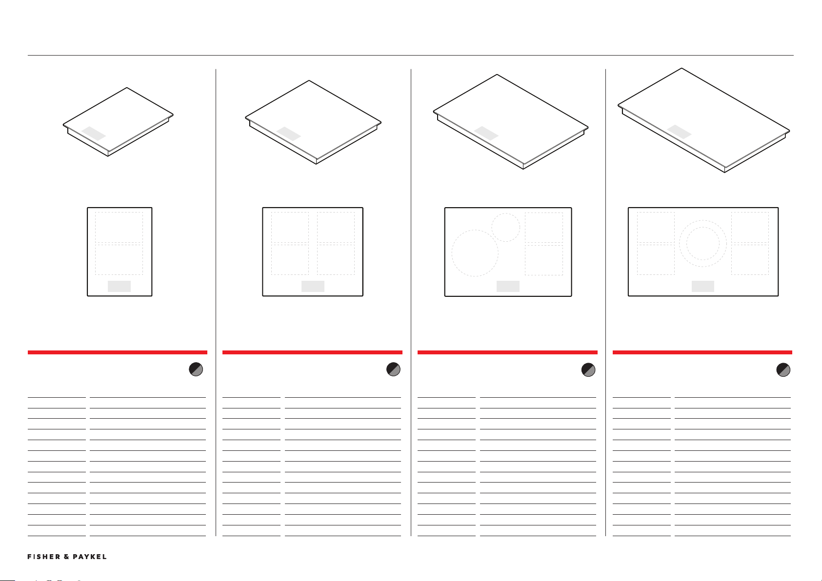
PRIMARY MODULES
PRIMARY MODULAR INDUCTION COOKTOP, 39CM,
2 ZONES WITH SMARTZONE
Model no:
CI92DTTB1 Black
CI92DTTG1 Grey
Dimensions
W x D x H
Product
85 x 50 x 62
Glass
85 x 50 x 6
Cutout, proud
47 x 507
Cutout, flush
47 x 509
Recess, flush
89 x 54 x 6.5
Power Requirements
Supply
220-240V, 50Hz/60Hz
Maximum Power
.7kW
Connection
Power cable, stripped wires, 1N
Weight
12kg
PRIMARY MODULAR INDUCTION COOKTOP, 60CM,
4 ZONES WITH SMARTZONE
Model no:
CI604DTTB1 Black
CI604DTTG1 Grey
Dimensions W x D x H
Product
600 x 50 x 62
Glass 85 x 50 x 6
Cutout, proud 562 x 507
Cutout, flush 562 x 509
Recess, flush 604 x 54 x 6.5
Power Requirements
Supply
220-240V, 50Hz/60Hz
Maximum Power
7.4kW
Connection
Terminal block, 1N or 2N
Weight 12kg
PRIMARY MODULAR INDUCTION COOKTOP, 76CM,
4 ZONES WITH SMARTZONE
Model no:
CI764DTTB1 Black
CI764DTTG1 Grey
Dimensions
W x D x H
Product
760 x 50 x 62
Glass
760 x 50 x 6
Cutout, proud
722 x 507
Cutout, flush
722 x 509
Recess, flush
764 x 54 x 6.5
Power Requirements
Supply
220-240V, 50Hz/60Hz
Maximum Power
7.4kW
Connection
Terminal block, 1N or 2N
Weight
1kg
PRIMARY MODULAR INDUCTION COOKTOP, 90CM,
5 ZONES WITH SMARTZONE
Model no:
CI905DTTB1 Black
CI905DTTG1 Grey
Dimensions
W x D x H
Product
900 x 50 x 62
Glass
900 x 50 x 6
Cutout, proud
862 x 507
Cutout, flush
862 x 509
Recess, flush
904 x 54 x 6.5
Power Requirements
Supply
220-240V, 50Hz/60Hz
Maximum Power
11.1kW
Connection
Terminal block, 1N or N
Weight
19kg
Primary Modules
PRODUCT SPECIFICATIONS | MODULAR COOKTOPS
© FISHER & PAYKEL LIMITED 202 PAGE 79000269A PLANNING GUIDE MODULAR COOKTOPS VERSION 1 - AUGUST 202
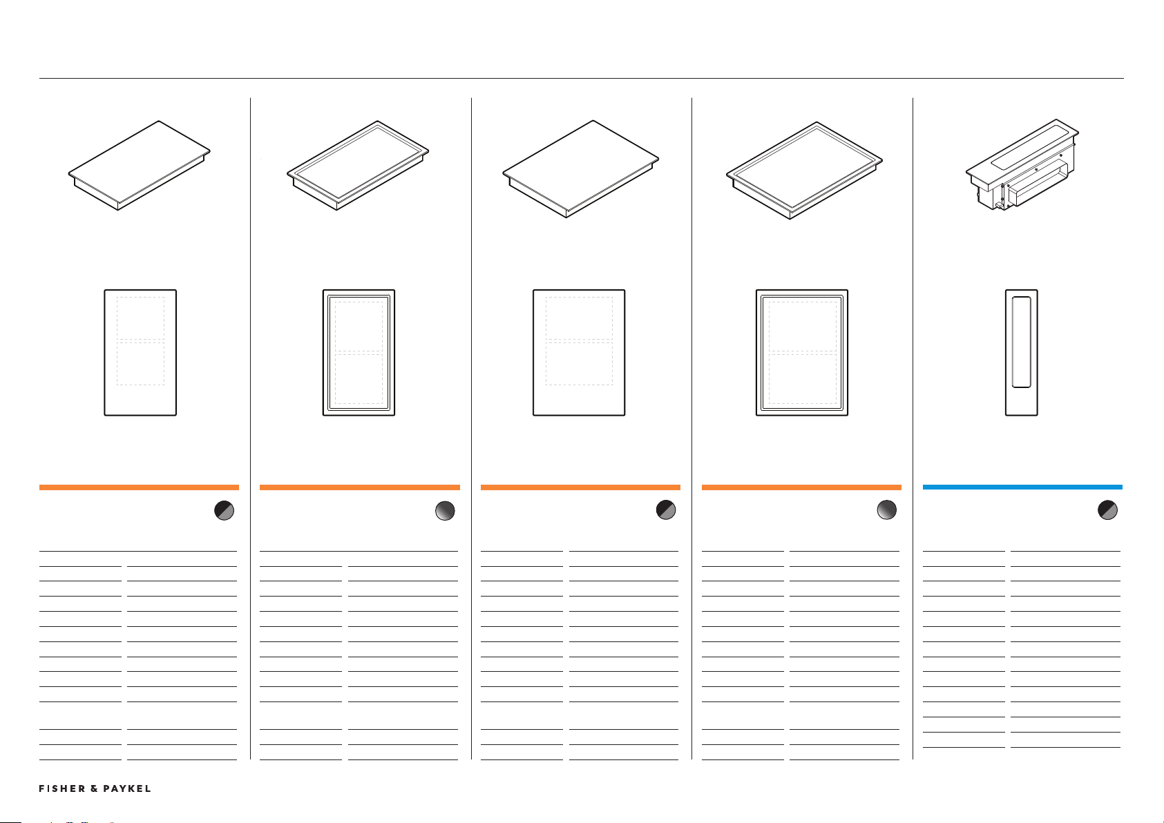
AUXILIARY MODULES
AUXILIARY MODULAR INDUCTION COOKTOP,
30CM, 2 ZONES WITH SMARTZONE
Model no:
CI02DB1 Black
CI02DG1 Grey
Dimensions
W x D x H
Product
00 x 50 x 62
Glass
00 x 50 x 6
Cutout, proud
262 x 507
Cutout, flush
262 x 509
Recess, flush
04 x 54 x 6.5
Power Requirements
Supply
220-240V, 50Hz/60Hz
Maximum Power
.7kW
Connection
Power cable, stripped
wires, 1N
Weight
11kg
AUXILIARY MODULAR INDUCTION COOKTOP,
39CM, 2 ZONES WITH SMARTZONE
Model no:
CI92DB1 Black
CI92DG1 Grey
Product Dimensions
W x D x H
Product
85 x 50 x 62
Glass
85 x 50 x 6
Cutout, proud
47 x 507
Cutout, flush
262 x 509
Recess, flush
04 x 54 x 6.5
Power Requirements
Supply
220-240V, 50Hz/60Hz
Maximum Power
.7kW
Connection
Power cable, stripped
wires, 1N
Weight
12kg
AUXILIARY MODULAR VENTILATION,
13CM
Model no:
CD1DB1 Black
CD1DG1 Grey
Product Dimensions
W x D x H
Product
10 x 50 x 186
Glass
10 x 50 x 6
Cutout, proud*
97 x 507
Cutout, flush*
97 x 509
Recess, flush*
14 x 54 x 6.5
Power Requirements
Supply
220-240V, 50Hz
Maximum Power
167W
Connection
Power cable, plug
Weight
kg
* Must be installed in combined cutout with cooktop
AUXILIARY MODULAR TEPPANYAKI
COOKTOP, 39CM, 2 ZONES
Model no:
CI92DX1
Product Dimensions
W x D x H
Product
85 x 50 x 74
Plate
85 x 50 x 6
Cutout, proud
47 x 507
Cutout, flush
262 x 509
Recess, flush
04 x 54 x 6.5
Power Requirements
Supply
220-240V, 50Hz/60Hz
Maximum Power
2.8kW
Connection
Power cable, stripped
wires, 1N
Weight
12kg
AUXILIARY MODULAR TEPPANYAKI COOKTOP,
30CM, 2 ZONES
Model no:
CIT02DX1
Product Dimensions
W x D x H
Product
00 x 50 x 74
Plate
00 x 50 x 6
Cutout, proud
262 x 507
Cutout, flush
262 x 509
Recess, flush
04 x 54 x 6.5
Power Requirements
Supply
220-240V, 50Hz/60Hz
Maximum Power
2.8kW
Connection
Power cable, stripped
wires, 1N
Weight
11kg
Auxiliary Modules
PRODUCT SPECIFICATIONS | MODULAR COOKTOPS

© FISHER & PAYKEL LIMITED 202 PAGE 89000269A PLANNING GUIDE MODULAR COOKTOPS - VERSION 1 - AUGUST 202
DATA SHEETS
© FISHER & PAYKEL LIMITED 202 PAGE 99000269A PLANNING GUIDE MODULAR COOKTOPS VERSION 1 - AUGUST 202 © FISHER & PAYKEL LIMITED 202 PAGE 99000269A PLANNING GUIDE MODULAR COOKTOPS VERSION 1 - AUGUST 202
INDICATES CABINETRY / PRODUCT DATUM -------------------------
INDICATES CABINETRY CLEARANCES --------------------------------
INDICATES CUTOUT -------------------------------------------------------
IMPORTANT NOTE: Throughout this guide, dimensions may vary by ±2mm (1/16''). Please read
the installation manual for detailed information on installing the product. For full installation
instructions & specifications visit fisherpaykel.com
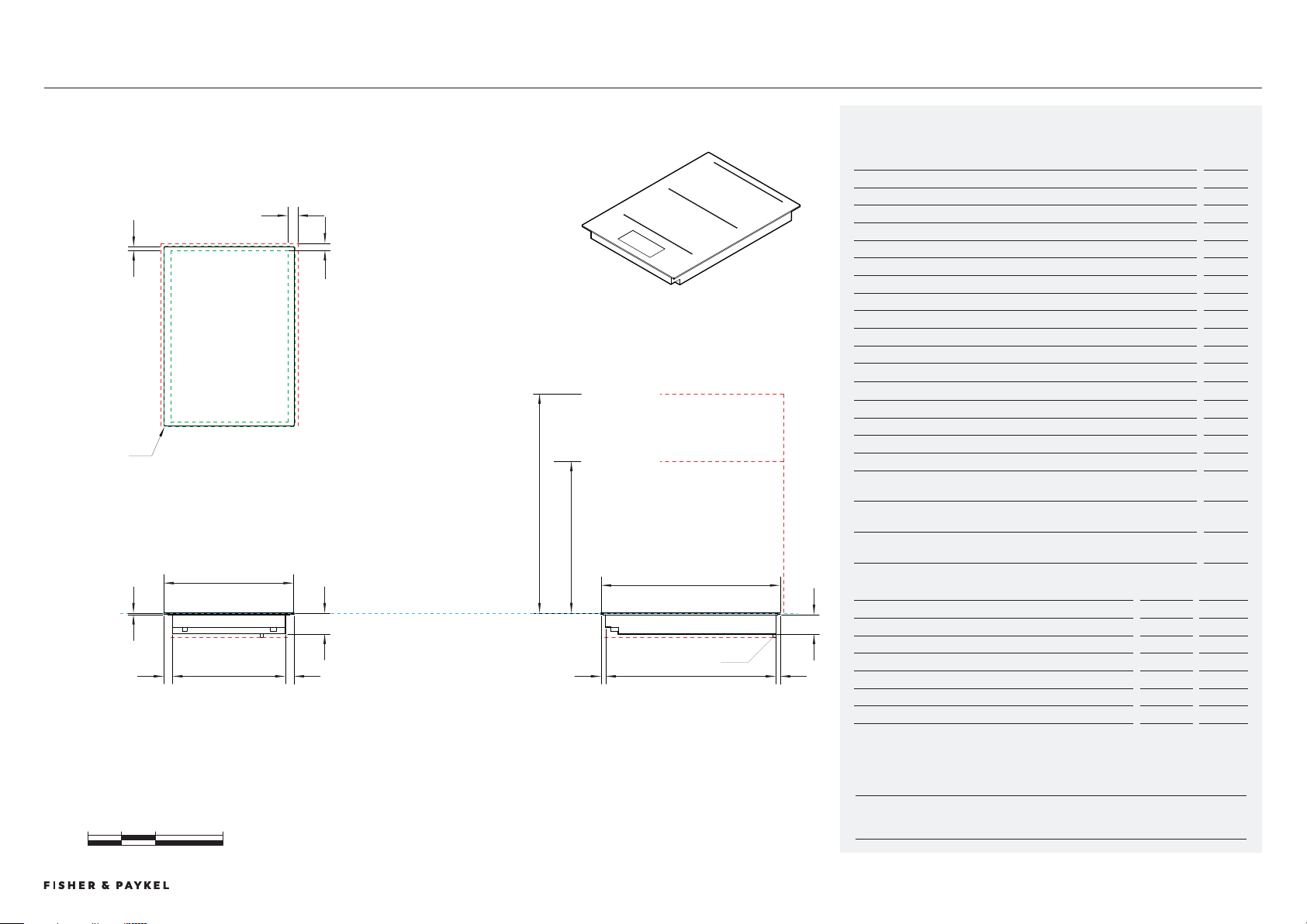
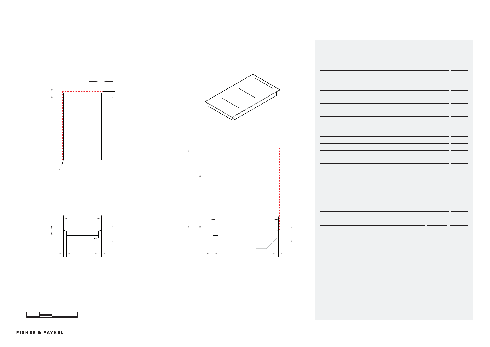
CI92DTTB1, CI92DTTG1
0 100 200 400
millimetres
CLEARANCE: REAR
TOP VIEW
m
l
k
e
CLEARANCE: SIDE
f
j k
h
CLEARANCE: BELOW COOKTOP
CLEARANCE: OVERHEAD CABINET NOT DIRECTLY ABOVE
CLEARANCE: RANGEHOOD
PROFILE VIEW
n
o
c
530
DATUM:
TOP OF COOK SURFACE
A
d
i
i
g
CLEARANCE: BELOW COOKTOP
FRONT VIEW
b
385
POWER OUTLET
Model no:
Primary Modular Induction Cooktop, 39cm, 2 Zones with Smartzone, Black - CI392DTTB1,
Primary Modular Induction Cooktop, 39cm, 2 Zones with Smartzone, Grey - CI392DTTG1
Product Dimensions
mm
a Overall height of cooktop
62
B Overall width of cooktop
85
c Overall depth of cooktop
50
d Height of cooktop glass (includes flange and tape)
6
e Corner radius of glass
2
f Height of chassis
56
G Width of chassis
4
h Depth of chassis
504
i Width from side edges of cooktop to chassis
26
j Depth from front edge of cooktop to chassis
14
k Depth from back edge of cooktop to chassis
1
Product Clearances
mm
l Minimum clearance from side edges of cutout to nearest combustible surface
29
m Minimum clearance from rear edge of cutout to nearest combustible surface
21
n Minimum clearance from glass surface to rangehood
650
o Minimum clearance from glass surface to overhead cabinet not directly above
cooktop
450
Minimum ventilation gap between bottom of benchtop and top of cabinetry
fronts (not shown)
4
Minimum clearance from glass surface to top of any appliances, companion
product or obstruction below cooktop
72
NOTE: The oven installed below the cooktop MUST have a cooling fan. It is important that the induction cooktop
receives adequate air supply. For ventilation requirements please refer to the installation manual.
Cutout Dimensions*
Proud mm
Flush mm
Overall width of cutout
47
47
Overall depth of cutout
507
509
Overall width of recess
-
89
Overall depth of recess
-
54
Overall height of recess
-
6.5
Recess corner radius
-
4
*Note cutout position is centred to the cooktop.
Primary Induction Cooktop, 9cm
DATA SHEETS | MODULAR COOKTOPSDATA SHEETS | MODULAR COOKTOPS
© FISHER & PAYKEL LIMITED 202 PAGE 109000269A PLANNING GUIDE MODULAR COOKTOPS VERSION 1 - AUGUST 202 © FISHER & PAYKEL LIMITED 202 PAGE 109000269A PLANNING GUIDE MODULAR COOKTOPS VERSION 1 - AUGUST 202
INDICATES CABINETRY / PRODUCT DATUM -------------------------
INDICATES CABINETRY CLEARANCES --------------------------------
INDICATES CUTOUT -------------------------------------------------------
IMPORTANT NOTE: Throughout this guide, dimensions may vary by ±2mm (1/16''). Please read
the installation manual for detailed information on installing the product. For full installation
instructions & specifications visit fisherpaykel.com
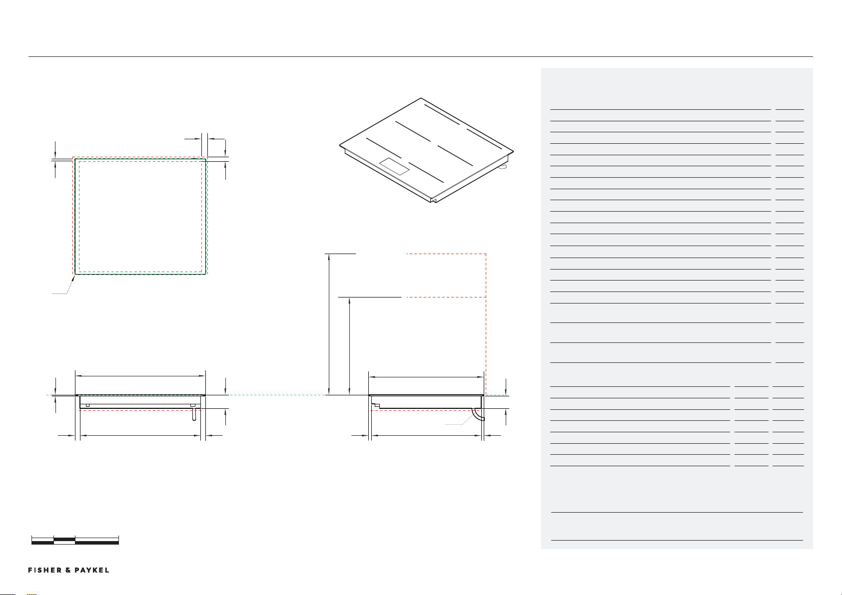
CI604DTTB1, CI604DTTG1
0 100 200 400
millimetres
CLEARANCE: REAR
TOP VIEW
m
l
k
e
CLEARANCE: SIDE
b
600
A
d
i
i
CLEARANCE: BELOW COOKTOP
g
FRONT VIEW
DATUM:
TOP OF COOK SURFACE
f
j k
h
CLEARANCE: BELOW COOKTOP
CLEARANCE: OVERHEAD CABINET NOT DIRECTLY ABOVE
CLEARANCE: RANGEHOOD
PROFILE VIEW
n
o
c
530
POWER OUTLET
Model no:
Primary Modular Induction Cooktop, 60cm, 4 Zones with Smartzone, Black - CI604DTTB1,
Primary Modular Induction Cooktop, 60cm, 4 Zones with Smartzone, Grey - CI604DTTG1
Product Dimensions
mm
a Overall height of cooktop
62
B Overall width of cooktop
600
c Overall depth of cooktop
50
d Height of cooktop glass (includes flange and tape)
6
e Corner radius of glass
2
f Height of chassis
56
G Width of chassis
554
h Depth of chassis
504
i Width from side edges of cooktop to chassis
2
j Depth from front edge of cooktop to chassis
14
k Depth from back edge of cooktop to chassis
1
Product Clearances
mm
l Minimum clearance from side edges of cutout to nearest combustible surface
29
m Minimum clearance from rear edge of cutout to nearest combustible surface
21
n Minimum clearance from glass surface to rangehood
650
o Minimum clearance from glass surface to overhead cabinet not directly above
cooktop
450
Minimum ventilation gap between bottom of benchtop and top of cabinetry
fronts (not shown)
4
Minimum clearance from glass surface to top of any appliances, companion
product or obstruction below cooktop
72
NOTE: The oven installed below the cooktop MUST have a cooling fan. It is important that the induction cooktop
receives adequate air supply. For ventilation requirements please refer to the installation manual.
Cutout Dimensions*
Proud mm
Flush mm
Overall width of cutout
562
562
Overall depth of cutout
507
509
Overall width of recess
-
604
Overall depth of recess
-
54
Overall height of recess
-
6.5
Recess corner radius
-
4
*Note cutout position is centred to the cooktop.
Primary Induction Cooktop, 60cm
DATA SHEETS | MODULAR COOKTOPS
© FISHER & PAYKEL LIMITED 202 PAGE 119000269A PLANNING GUIDE MODULAR COOKTOPS VERSION 1 - AUGUST 202 © FISHER & PAYKEL LIMITED 202 PAGE 119000269A PLANNING GUIDE MODULAR COOKTOPS VERSION 1 - AUGUST 202
INDICATES CABINETRY / PRODUCT DATUM -------------------------
INDICATES CABINETRY CLEARANCES --------------------------------
INDICATES CUTOUT -------------------------------------------------------
IMPORTANT NOTE: Throughout this guide, dimensions may vary by ±2mm (1/16''). Please read
the installation manual for detailed information on installing the product. For full installation
instructions & specifications visit fisherpaykel.com
CI764DTTB1, CI764DTTG1
0 100 200 400
millimetres
A
f
d
i
i
g
j k
h
CLEARANCE: BELOW COOKTOP
CLEARANCE: BELOW COOKTOP
CLEARANCE: OVERHEAD CABINET NOT DIRECTLY ABOVE
CLEARANCE: RANGEHOOD
PROFILE VIEWFRONT VIEW
b
760
n
o
CLEARANCE: REAR
TOP VIEW
CLEARANCE: SIDE
m
l
k
e
DATUM:
TOP OF COOK SURFACE
c
530
POWER OUTLET
Model no:
Primary Modular Induction Cooktop, 76cm, 4 Zones with Smartzone, Black - CI764DTTB1,
Primary Modular Induction Cooktop, 76cm, 4 Zones with Smartzone, Grey - CI764DTTG1
Product Dimensions
mm
a Overall height of cooktop
62
B Overall width of cooktop
760
c Overall depth of cooktop
50
d Height of cooktop glass (includes flange and tape)
6
e Corner radius of glass
2
f Height of chassis
56
G Width of chassis
714
h Depth of chassis
504
i Width from side edges of cooktop to chassis
2
j Depth from front edge of cooktop to chassis
14
k Depth from back edge of cooktop to chassis
1
Product Clearances
mm
l Minimum clearance from side edges of cutout to nearest combustible surface
29
m Minimum clearance from rear edge of cutout to nearest combustible surface
21
n Minimum clearance from glass surface to rangehood
650
o Minimum clearance from glass surface to overhead cabinet not directly above
cooktop
450
Minimum ventilation gap between bottom of benchtop and top of cabinetry
fronts (not shown)
4
Minimum clearance from glass surface to top of any appliances, companion
product or obstruction below cooktop
72
NOTE: The oven installed below the cooktop MUST have a cooling fan. It is important that the induction cooktop
receives adequate air supply. For ventilation requirements please refer to the installation manual.
Cutout Dimensions*
Proud mm
Flush mm
Overall width of cutout
722
722
Overall depth of cutout
507
509
Overall width of recess
-
764
Overall depth of recess
-
54
Overall height of recess
-
6.5
Recess corner radius
-
4
*Note cutout position is centred to the cooktop.
Primary Induction Cooktop, 76cm
DATA SHEETS | MODULAR COOKTOPS
© FISHER & PAYKEL LIMITED 202 PAGE 129000269A PLANNING GUIDE MODULAR COOKTOPS VERSION 1 - AUGUST 202 © FISHER & PAYKEL LIMITED 202 PAGE 129000269A PLANNING GUIDE MODULAR COOKTOPS VERSION 1 - AUGUST 202
INDICATES CABINETRY / PRODUCT DATUM -------------------------
INDICATES CABINETRY CLEARANCES --------------------------------
INDICATES CUTOUT -------------------------------------------------------
IMPORTANT NOTE: Throughout this guide, dimensions may vary by ±2mm (1/16''). Please read
the installation manual for detailed information on installing the product. For full installation
instructions & specifications visit fisherpaykel.com
0 100 200 400
millimetres
CLEARANCE: SIDE
A
f
d
i
i
g
j
k
h
DATUM:
TOP OF COOK SURFACE
CLEARANCE: REAR
CLEARANCE: BELOW COOKTOP
CLEARANCE: BELOW COOKTOP
CLEARANCE: OVERHEAD CABINET NOT DIRECTLY ABOVE
CLEARANCE: RANGEHOOD
TOP VIEW
PROFILE VIEWFRONT VIEW
b
900
n
o
m
l
k
c
530
e
POWER OUTLET
CI905DTTB1, CI905DTTG1
Model no:
Primary Modular Induction Cooktop, 90cm, 5 Zones with Smartzone, Black - CI905DTTB1
Primary Modular Induction Cooktop, 90cm, 5 Zones with Smartzone, Grey - CI905DTTG1
Product Dimensions
mm
a Overall height of cooktop
62
B Overall width of cooktop
900
c Overall depth of cooktop
50
d Height of cooktop glass (includes flange and tape)
6
e Corner radius of glass
2
f Height of chassis
56
G Width of chassis
854
h Depth of chassis
504
i Width from side edges of cooktop to chassis
2
j Depth from front edge of cooktop to chassis
14
k Depth from back edge of cooktop to chassis
1
Product Clearances
mm
l Minimum clearance from side edges of cutout to nearest combustible surface
29
m Minimum clearance from rear edge of cutout to nearest combustible surface
21
n Minimum clearance from glass surface to rangehood
650
o Minimum clearance from glass surface to overhead cabinet not directly above
cooktop
450
Minimum ventilation gap between bottom of benchtop and top of cabinetry
fronts (not shown)
4
Minimum clearance from glass surface to top of any appliances, companion
product or obstruction below cooktop
72
NOTE: The oven installed below the cooktop MUST have a cooling fan. It is important that the induction cooktop
receives adequate air supply. For ventilation requirements please refer to the installation manual.
Cutout Dimensions*
Proud mm
Flush mm
Overall width of cutout
862
862
Overall depth of cutout
507
509
Overall width of recess
-
904
Overall depth of recess
-
54
Overall height of recess
-
6.5
Recess corner radius
-
4
*Note cutout position is centred to the cooktop.
Primary Induction Cooktop, 90cm
DATA SHEETS | MODULAR COOKTOPS
© FISHER & PAYKEL LIMITED 202 PAGE 19000269A PLANNING GUIDE MODULAR COOKTOPS VERSION 1 - AUGUST 202 © FISHER & PAYKEL LIMITED 202 PAGE 19000269A PLANNING GUIDE MODULAR COOKTOPS VERSION 1 - AUGUST 202
INDICATES CABINETRY / PRODUCT DATUM -------------------------
INDICATES CABINETRY CLEARANCES --------------------------------
INDICATES CUTOUT -------------------------------------------------------
IMPORTANT NOTE: Throughout this guide, dimensions may vary by ±2mm (1/16''). Please read
the installation manual for detailed information on installing the product. For full installation
instructions & specifications visit fisherpaykel.com
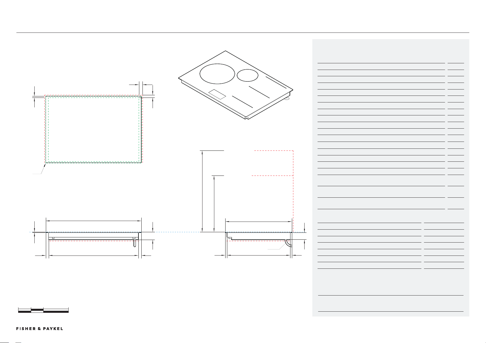
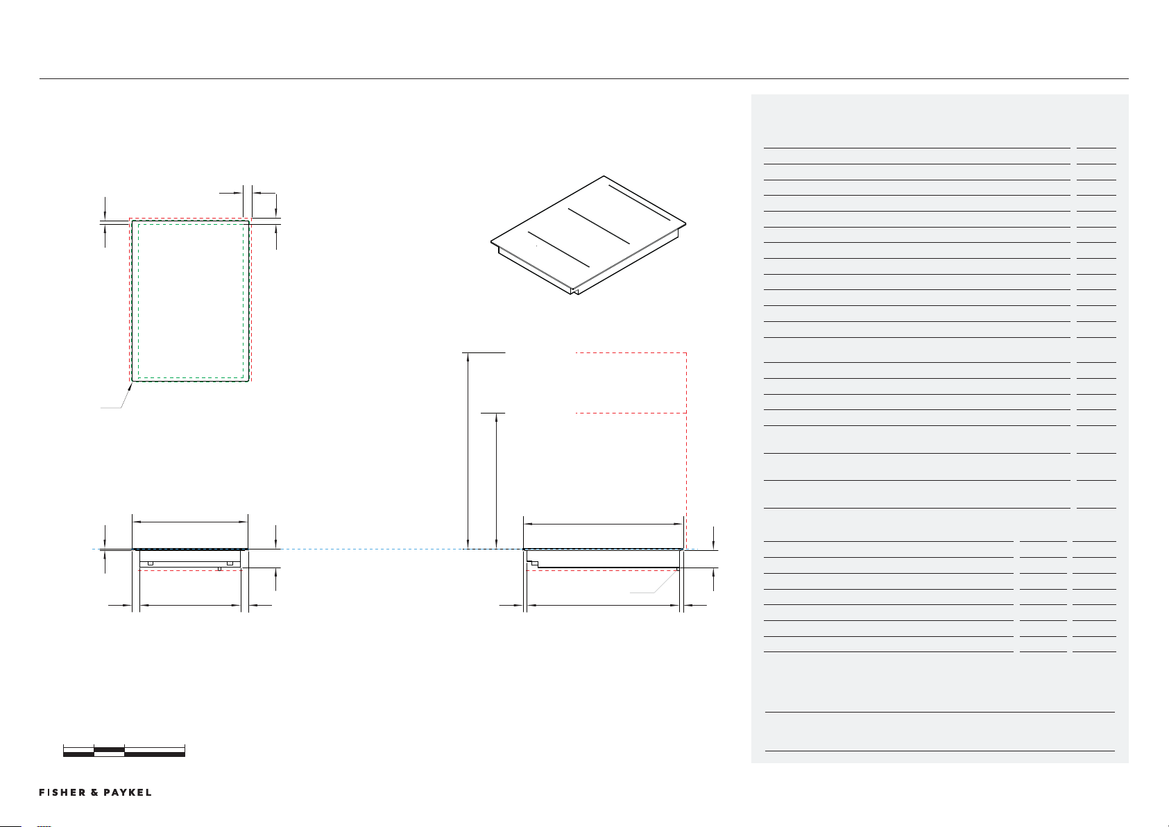
CI02DB1, CI02DG1
0 100 200 400
millimetres
CLEARANCE: REAR
TOP VIEW
CLEARANCE: SIDE
m
l
e
k
A
d
i
i
g
CLEARANCE: BELOW COOKTOP
FRONT VIEW
b
300
f
j k
h
CLEARANCE: BELOW COOKTOP
CLEARANCE: OVERHEAD CABINET NOT DIRECTLY ABOVE
CLEARANCE: RANGEHOOD
PROFILE VIEW
n
o
c
530
DATUM:
TOP OF COOK SURFACE
POWER OUTLET
Model no:
Auxiliary Modular Induction Cooktop, 30cm, 2 Zones with Smartzone, Black - CI302DB1
Auxiliary Modular Induction Cooktop, 30cm, 2 Zones with Smartzone, Grey - CI302DG1
Product Dimensions
mm
a Overall height of cooktop
62
B Overall width of cooktop
00
c Overall depth of cooktop
50
d Height of cooktop glass (includes flange and tape)
6
e Corner radius of glass
2
f Height of chassis
56
G Width of chassis
254
h Depth of chassis
504
i Width from side edges of cooktop to chassis
2
j Depth from front edge of cooktop to chassis
14
k Depth from back edge of cooktop to chassis
1
Product Clearances
mm
l Minimum clearance from side edges of cutout to nearest combustible surface
29
m Minimum clearance from rear edge of cutout to nearest combustible surface
21
n Minimum clearance from glass surface to rangehood
650
o Minimum clearance from glass surface to overhead cabinet not directly above
cooktop
450
Minimum ventilation gap between bottom of benchtop and top of cabinetry
fronts (not shown)
4
Minimum clearance from glass surface to top of any appliances, companion
product or obstruction below cooktop
72
NOTE: The oven installed below the cooktop MUST have a cooling fan. It is important that the induction cooktop
receives adequate air supply. For ventilation requirements please refer to the installation manual.
Cutout Dimensions*
Proud mm
Flush mm
Overall width of cutout
262
262
Overall depth of cutout
507
509
Overall width of recess
-
04
Overall depth of recess
-
54
Overall height of recess
-
6.5
Recess corner radius
-
4
*Note cutout position is centred to the cooktop.
Auxiliary Induction Cooktop, 0cm
DATA SHEETS | MODULAR COOKTOPS
© FISHER & PAYKEL LIMITED 202 PAGE 149000269A PLANNING GUIDE MODULAR COOKTOPS VERSION 1 - AUGUST 202 © FISHER & PAYKEL LIMITED 202 PAGE 149000269A PLANNING GUIDE MODULAR COOKTOPS VERSION 1 - AUGUST 202
INDICATES CABINETRY / PRODUCT DATUM -------------------------
INDICATES CABINETRY CLEARANCES --------------------------------
INDICATES CUTOUT -------------------------------------------------------
IMPORTANT NOTE: Throughout this guide, dimensions may vary by ±2mm (1/16''). Please read
the installation manual for detailed information on installing the product. For full installation
instructions & specifications visit fisherpaykel.com
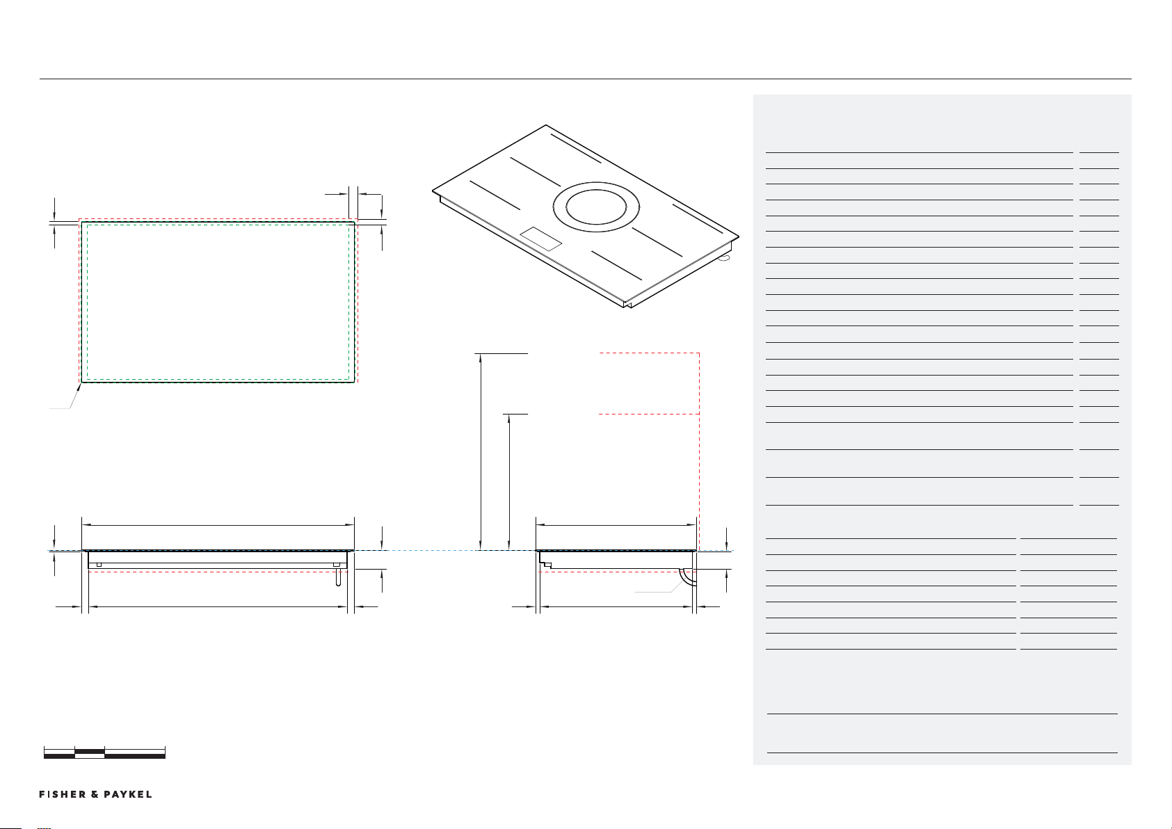
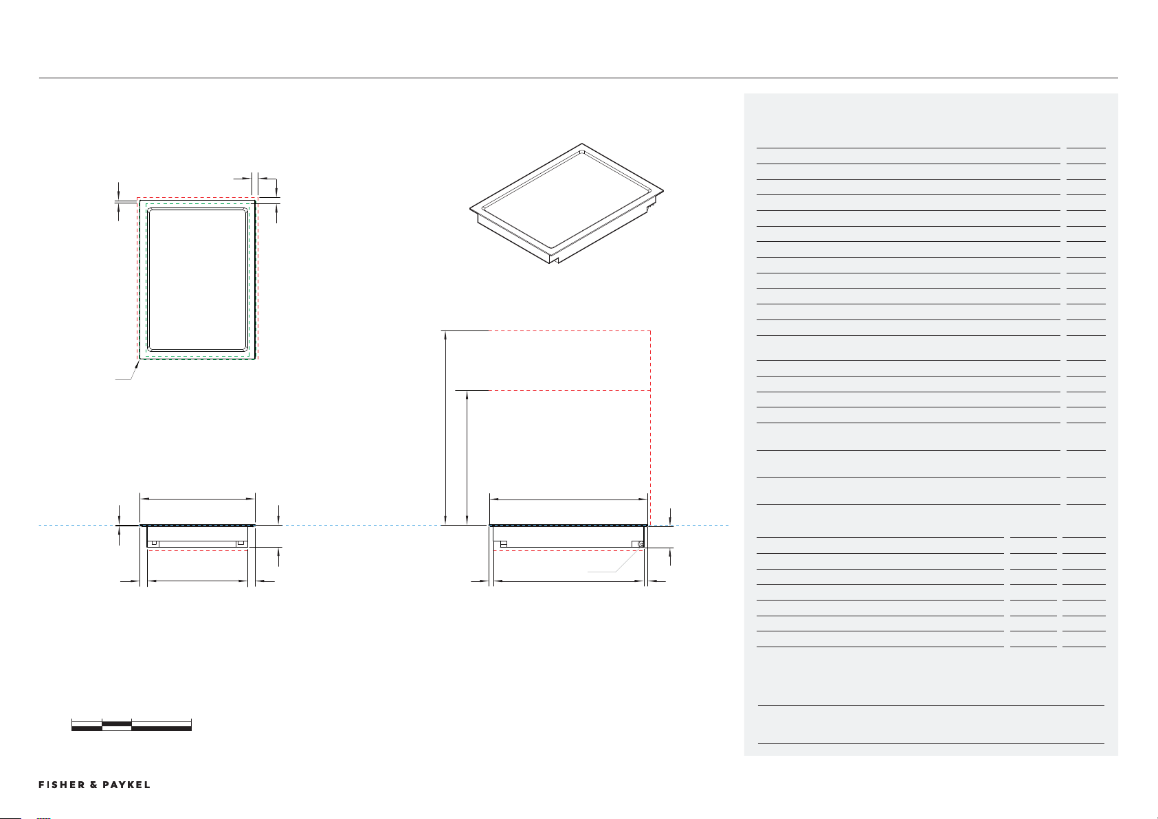
CIT02DX1
0 100 200 400
millimetres
FRONT VIEW
TOP VIEW
f
j k
h
CLEARANCE: BELOW COOKTOP
CLEARANCE: OVERHEAD CABINET NOT DIRECTLY ABOVE
CLEARANCE: RANGEHOOD
PROFILE VIEW
n
o
c
530
DATUM:
TOP OF COOK SURFACE
CLEARANCE: REAR
TOP VIEW
CLEARANCE: SIDE
e
m
l
k
b
300
A
d
i
i
CLEARANCE: BELOW COOKTOP
g
POWER OUTLET
Model no:
Auxiliary Modular Teppanyaki Cooktop 30cm, 2 Zones - CIT302DX1
Product Dimensions
mm
a Overall height of cooktop
74
B Overall width of cooktop
00
c Overall depth of cooktop
50
d Height of cooktop plate (includes flange and tape)
6
e Corner radius of cooktop surface
2
f Height of chassis
68
G Width of chassis
251
h Depth of chassis
504
i Width from side edges of cooktop to chassis
25
j Depth from front edge of cooktop to chassis
14
k Depth from back edge of cooktop to chassis
1
Product Clearances
mm
l Minimum clearance from side edges of cutout to nearest combustible surface
29
m Minimum clearance from rear edge of cutout to nearest combustible surface
21
n Minimum clearance from glass surface to rangehood
650
o Minimum clearance from glass surface to overhead cabinet not directly above
cooktop
450
Minimum ventilation gap between bottom of benchtop and top of cabinetry
fronts (not shown)
4
Minimum clearance from glass surface to top of any appliances, companion
product or obstruction below cooktop
86
NOTE: The oven installed below the cooktop MUST have a cooling fan. It is important that the induction cooktop
receives adequate air supply. For ventilation requirements please refer to the installation manual.
Cutout Dimensions*
Proud mm
Flush mm
Overall width of cutout
262
262
Overall depth of cutout
507
509
Overall width of recess
-
04
Overall depth of recess
-
54
Overall height of recess
-
6.5
Recess corner radius
-
4
*Note cutout position is centred to the cooktop.
Auxiliary Teppanyaki Cooktop, 0cm
DATA SHEETS | MODULAR COOKTOPS
© FISHER & PAYKEL LIMITED 202 PAGE 159000269A PLANNING GUIDE MODULAR COOKTOPS VERSION 1 - AUGUST 202 © FISHER & PAYKEL LIMITED 202 PAGE 159000269A PLANNING GUIDE MODULAR COOKTOPS VERSION 1 - AUGUST 202
INDICATES CABINETRY / PRODUCT DATUM -------------------------
INDICATES CABINETRY CLEARANCES --------------------------------
INDICATES CUTOUT -------------------------------------------------------
IMPORTANT NOTE: Throughout this guide, dimensions may vary by ±2mm (1/16''). Please read
the installation manual for detailed information on installing the product. For full installation
instructions & specifications visit fisherpaykel.com
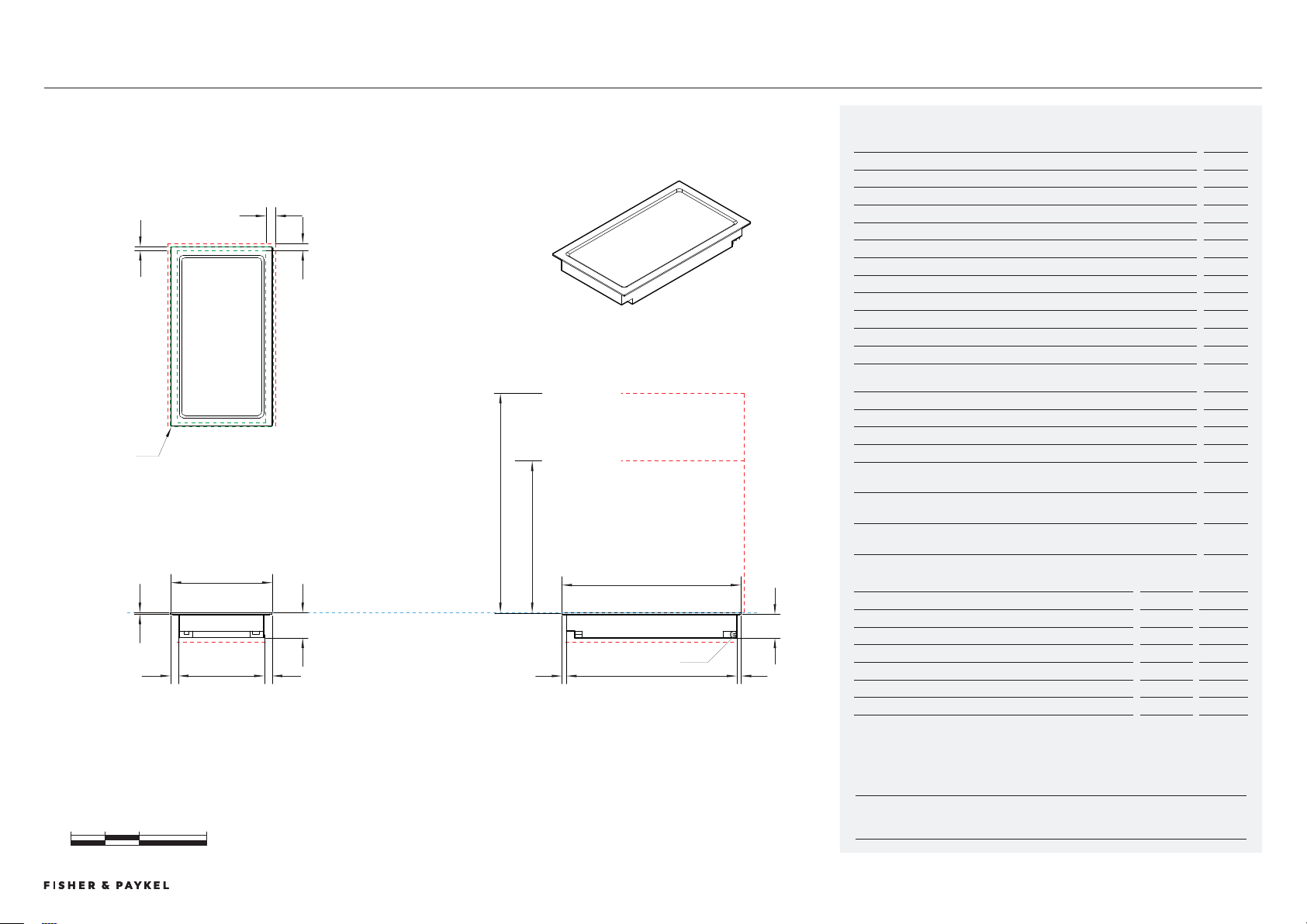
CI92DB1, CI92DG1
0 100 200 400
millimetres
CLEARANCE: REAR
TOP VIEW
m
l
k
e
CLEARANCE: SIDE
f
j k
h
CLEARANCE: BELOW COOKTOP
CLEARANCE: OVERHEAD CABINET NOT DIRECTLY ABOVE
CLEARANCE: RANGEHOOD
PROFILE VIEW
n
o
c
530
DATUM:
TOP OF COOK SURFACE
A
d
i
i
g
CLEARANCE: BELOW COOKTOP
FRONT VIEW
b
385
POWER OUTLET
Model no:
Auxiliary Modular Induction Cooktop, 39cm, 2 Zones with Smartzone, Black - CI392DB1
Auxiliary Modular Induction Cooktop, 39cm, 2 Zones with Smartzone, Grey - CI392DG1
Product Dimensions
mm
a Overall height of cooktop
62
B Overall width of cooktop
85
c Overall depth of cooktop
50
d Height of cooktop glass (includes flange and tape)
6
e Corner radius of glass
2
f Height of chassis
56
G Width of chassis
4
h Depth of chassis
504
i Width from side edges of cooktop to chassis
26
j Depth from front edge of cooktop to chassis
14
k Depth from back edge of cooktop to chassis
1
Product Clearances
mm
l Minimum clearance from side edges of cutout to nearest combustible surface
29
m Minimum clearance from rear edge of cutout to nearestcombustible surface
21
n Minimum clearance from glass surface to rangehood
650
o Minimum clearance from glass surface to overhead cabinet not
directly above cooktop
450
Minimum ventilation gap between bottom of benchtop and top of cabinetry
fronts (not shown)
4
Minimum clearance from glass surface to top of any appliances, companion
product or obstruction below cooktop
72
NOTE: The oven installed below the cooktop MUST have a cooling fan. It is important that the induction cooktop
receives adequate air supply. For ventilation requirements please refer to the installation manual.
Cutout Dimensions*
Proud mm
Flush mm
Overall width of cutout
47
47
Overall depth of cutout
507
509
Overall width of recess
-
89
Overall depth of recess
-
54
Overall height of recess
-
6.5
Recess corner radius
-
4
*Note cutout position is centred to the cooktop.
Auxiliary Induction Cooktop, 9cm
DATA SHEETS | MODULAR COOKTOPS
© FISHER & PAYKEL LIMITED 202 PAGE 169000269A PLANNING GUIDE MODULAR COOKTOPS VERSION 1 - AUGUST 202 © FISHER & PAYKEL LIMITED 202 PAGE 169000269A PLANNING GUIDE MODULAR COOKTOPS VERSION 1 - AUGUST 202
INDICATES CABINETRY / PRODUCT DATUM -------------------------
INDICATES CABINETRY CLEARANCES --------------------------------
INDICATES CUTOUT -------------------------------------------------------
IMPORTANT NOTE: Throughout this guide, dimensions may vary by ±2mm (1/16''). Please read
the installation manual for detailed information on installing the product. For full installation
instructions & specifications visit fisherpaykel.com
CIT92DBX1
Model no:
Auxiliary Modular Teppanyaki Cooktop 39cm, 2 Zones - CIT392DBX1
Product Dimensions
mm
a Overall height of cooktop
74
B Overall width of cooktop
85
c Overall depth of cooktop
50
d Height of cooktop plate (includes flange and tape)
6
e Radius of the corner
2
f Height of chassis
68
G Width of chassis
6
h Depth of chassis
504
i Width from side edges of cooktop to chassis
25
j Depth from front edge of cooktop to chassis
14
k Depth from back edge of cooktop to chassis
1
Product Clearances
mm
l Minimum clearance from side edges of cutout to nearest combustible surface
29
m Minimum clearance from rear edge of cutout to nearest combustible surface
21
n Minimum clearance from glass surface to rangehood
650
o Minimum clearance from glass surface to overhead cabinet not directly above
cooktop
450
Minimum ventilation gap between bottom of benchtop and top of cabinetry
fronts (not shown)
4
Minimum clearance from glass surface to top of any appliances, companion
product or obstruction below cooktop
86
NOTE: The oven installed below the cooktop MUST have a cooling fan. It is important that the teppanyaki
cooktop receives adequate air supply. For ventilation requirements please refer to page
Cutout Dimensions*
Proud mm
Flush mm
Overall width of cutout
46
46
Overall depth of cutout
507
509
Overall width of recess
-
89
Overall depth of recess
-
54
Overall height of recess
-
6.5
Recess corner radius
-
4
*Note cutout position is centred to the cooktop.
0 100 200 400
millimetres
CLEARANCE: REAR
CLEARANCE: SIDE
CLEARANCE: OVERHEAD CABINET NOT DIRECTLY ABOVE
CLEARANCE: RANGEHOOD
CLEARANCE: BELOW COOKTOP
CLEARANCE: BELOW COOKTOP
DATUM:
TOP OF COOK SURFACE
TOP VIEW
FRONT VIEW PROFILE VIEW
e
m
l
k
i
d
b
385
g
A
i
n o
j
c
530
f
h
k
POWER OUTLET
Auxiliary Teppanyaki Cooktop, 9cm
DATA SHEETS | MODULAR COOKTOPS
© FISHER & PAYKEL LIMITED 202 PAGE 179000269A PLANNING GUIDE MODULAR COOKTOPS VERSION 1 - AUGUST 202 © FISHER & PAYKEL LIMITED 202 PAGE 179000269A PLANNING GUIDE MODULAR COOKTOPS VERSION 1 - AUGUST 202
0 100 200 400
millimetres
FRONT VIEW
PROFILE VIEW
b
A
d
g
f
j
k
530
c
h
TOP VIEW
e
k
DATUM:
TOP OF COOK SURFACE
130
17.5
36
??
124
279
m
l
I
N
0 100 200 400
millimetres
0 100 200 400
millimetres
0 100 200 400
millimetres
0 100 200 400
millimetres
0 100 200 400
millimetres
0 100 200 400
millimetres
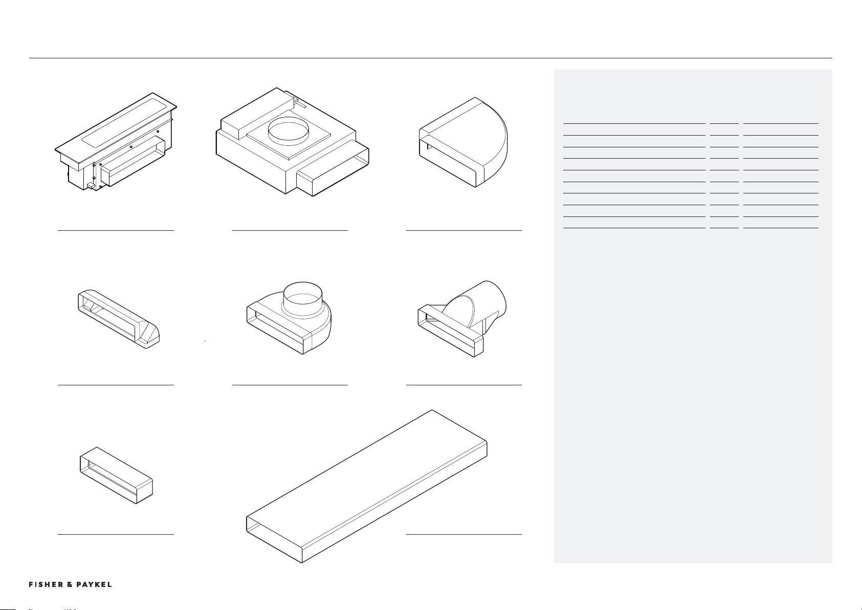
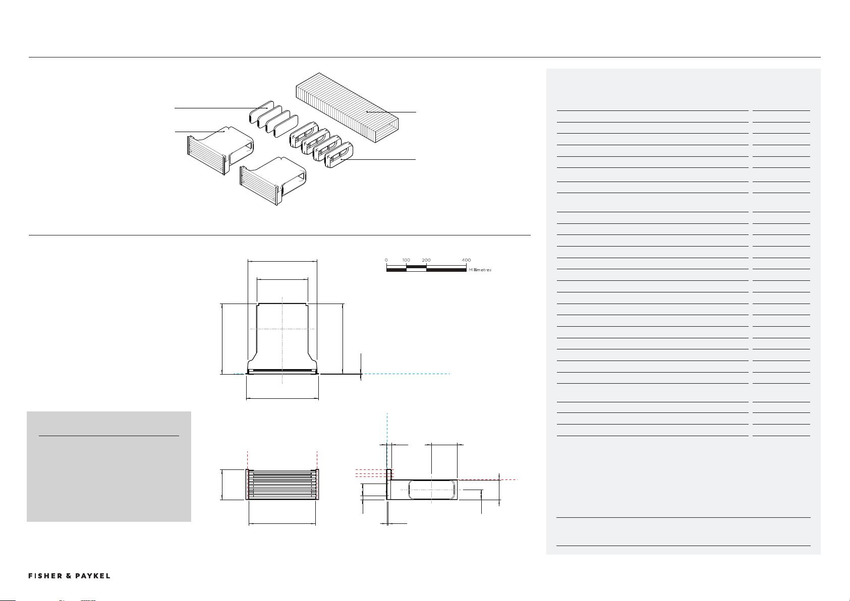
MAINBOX BLOWERBOX HORIZONTAL ELBOW, 90
Auxiliary Ventilation Components
Model no:
Auxiliary Modular Ventilation, 13cm, Black - DD13DB1
Auxiliary Modular Ventilation, 13cm, Grey - DD13DG1
Component Description Supplied
Optional Accessory
Mainbox
x1
Blowerbox
x1
Horizontal Elbow, 90°, 00x70*
x1
E90H300X70
Vertical Elbow, 90°, 00x70*
x2
DA90D300X70D150
Duct Adapter, 90°, 00x70, 150mm Diameter*
x1
DA90D300X70D150
Duct Adapter, 00x70, 150mm Diameter*
x1
DA300X70D150
Connector, 00x70*
x1
C300X70
Duct, 00x70, 1m*
x1
D1C300X70
* Component also available as an optional accessory
DATA SHEETS | MODULAR COOKTOPS CD1DB1, CD1BG1
VERTICAL ELBOW, 90 DUCT ADAPTER, 90 DUCT ADAPTER, 90
CONNECTOR DUCT
© FISHER & PAYKEL LIMITED 202 PAGE 189000269A PLANNING GUIDE MODULAR COOKTOPS VERSION 1 - AUGUST 202 © FISHER & PAYKEL LIMITED 202 PAGE 189000269A PLANNING GUIDE MODULAR COOKTOPS VERSION 1 - AUGUST 202
INDICATES CABINETRY / PRODUCT DATUM -------------------------
INDICATES CABINETRY CLEARANCES --------------------------------
INDICATES CUTOUT -------------------------------------------------------
IMPORTANT NOTE: Throughout this guide, dimensions may vary by ±2mm (1/16''). Please read
the installation manual for detailed information on installing the product. For full installation
instructions & specifications visit fisherpaykel.com
CD1DB1, CD1BG1
0 100 200 400
millimetres
FRONT VIEW
PROFILE VIEW
b
A
d
g
f
j
k
530
c
h
TOP VIEW
e
k
DATUM:
TOP OF COOK SURFACE
130
17.5
36
??
124
279
m
l
I
N
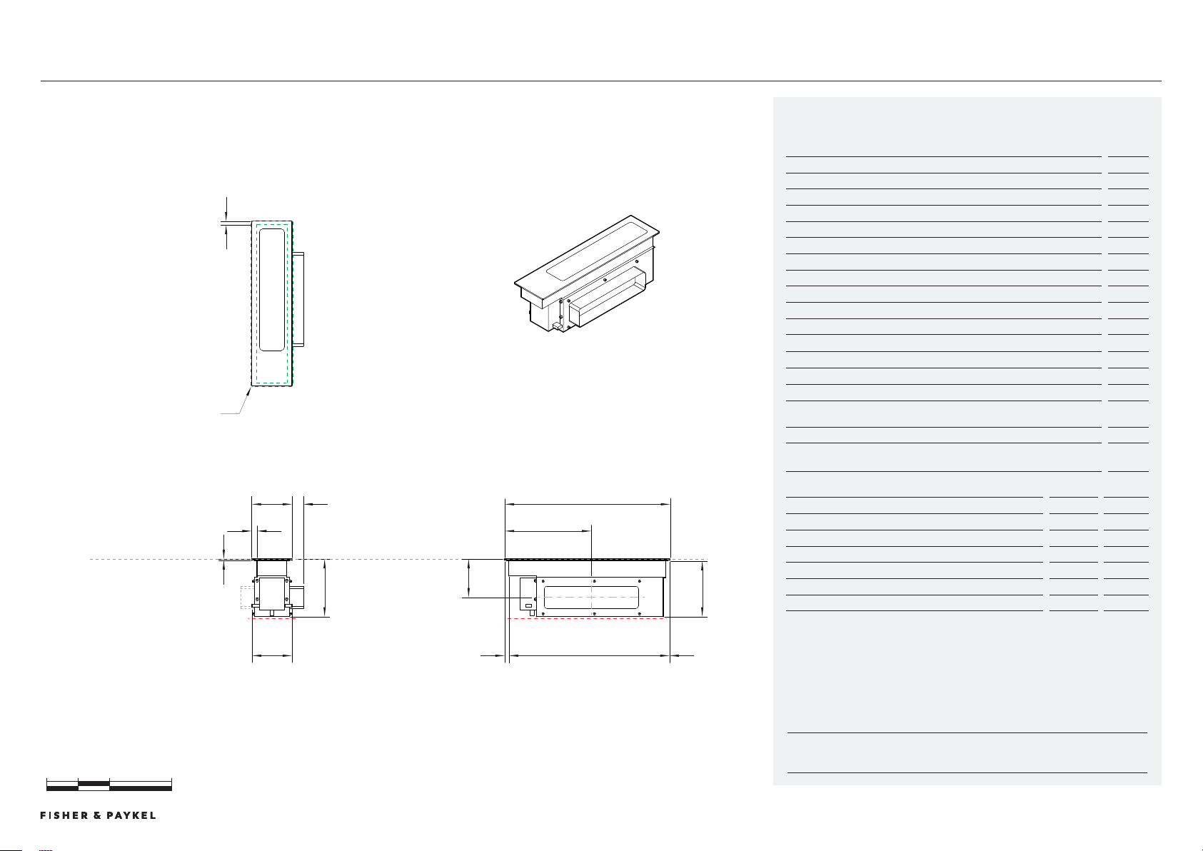
Model no:
Auxiliary Modular Ventilation, 13cm, Black - DD13DB1
Auxiliary Modular Ventilation, 13cm, Grey - DD13DG1
Product Dimensions
mm
a Overall height of downdraft mainbox
186
B Overall width of downdraft mainbox
10
c Overall depth of downdraft mainbox
50
d Height of glass (includes flange and tape)
6
e Corner radius of glass
2
f Height of chassis
180
G Width of lower chassis (includes communcation ports)
126
h Depth of chassis
504
i Width from sides of glass to neck of chassis
18
j Depth from front edge of downdraft to chassis
14
k Depth from back edge of downdraft to chassis
1
l Height from top of glass to centre of outlet
124
m Depth from front edge of downdraft centre of outlet
279
n Width from edge of glass to outside of outlet
6
Product Clearances
mm
Minimum clearance from top surface to top of any appliances, companion
product or obstruction below downdraft
200
Cutout Dimensions*
Proud mm
Flush mm
Overall width of cutout
96
96
Overall depth of cutout
507
509
Overall width of recess
-
14
Overall depth of recess
-
54
Overall height of recess
-
6.5
Recess corner radius
-
4
*Note cutout position is centred to the cooktop.
Mainbox
DATA SHEETS | MODULAR COOKTOPS
© FISHER & PAYKEL LIMITED 202 PAGE 199000269A PLANNING GUIDE MODULAR COOKTOPS VERSION 1 - AUGUST 202 © FISHER & PAYKEL LIMITED 202 PAGE 199000269A PLANNING GUIDE MODULAR COOKTOPS VERSION 1 - AUGUST 202
INDICATES CABINETRY / PRODUCT DATUM -------------------------
INDICATES CABINETRY CLEARANCES --------------------------------
INDICATES CUTOUT -------------------------------------------------------
IMPORTANT NOTE: Throughout this guide, dimensions may vary by ±2mm (1/16''). Please read
the installation manual for detailed information on installing the product. For full installation
instructions & specifications visit fisherpaykel.com
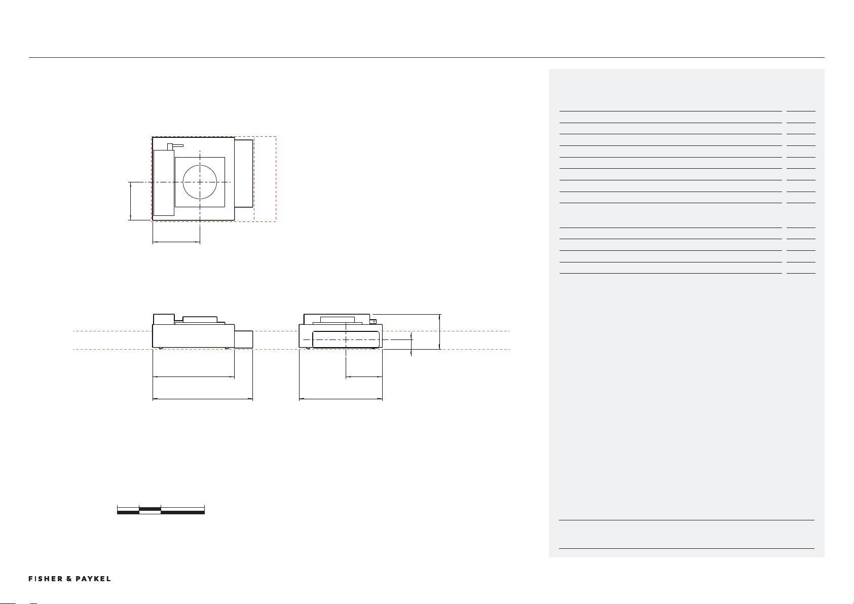
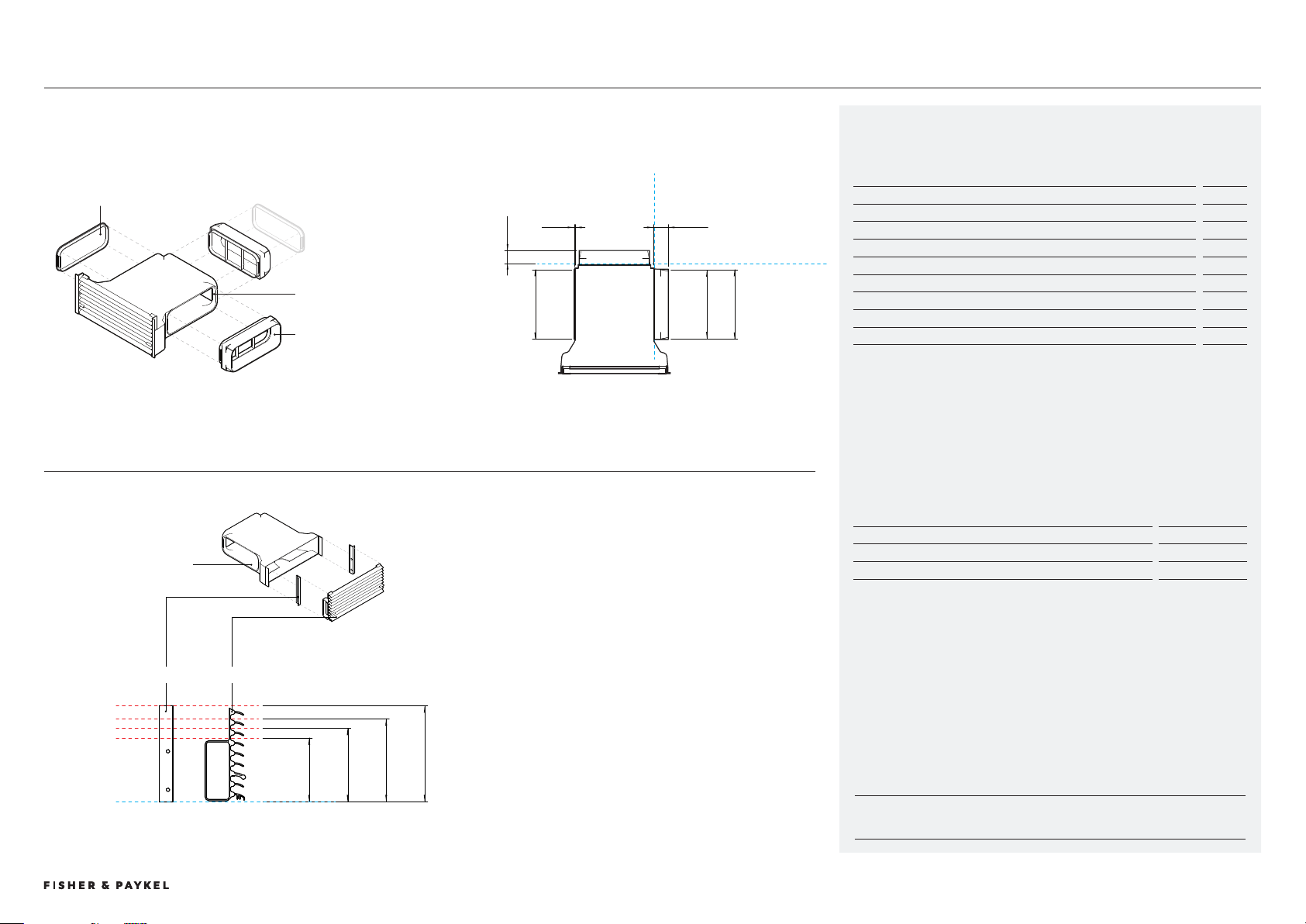
Blowerbox
CD1DB1, CD1BG1DATA SHEETS | MODULAR COOKTOPS
Model no:
Auxiliary Modular Ventilation, 13cm, Black - DD13DB1
Auxiliary Modular Ventilation, 13cm, Grey - DD13DG1
Product Dimensions
mm
a Overall height of downdraft blowerbox
155
B Overall width of downdraft blowerbox (including outlet connector)
458
c Overall depth of downdraft blowerbox
79
d Width from corner to centre of inlet
217
e Depth from corner to centre of inlet
175
f Width from outside of chassis to centre of outlet
166
G Height from base of product to centre of outlet
40
Cutout Dimensions*
mm
Recommended width of cutout **
570
Minimum width of cutout ***
470
Depth of cutout
90
*Blowerbox can be rotated to achieve desired outlet direction, cutout dimensions must be
similarly rotated.
** Recommended width allows greater access to outlet for connecting ducting during
installation.
*** Clearance only for blowerbox, does not provide allowances for connecting to ducting
within kickstrip
a
b c
d
379.0
165.8
458.0
216.5
174.5
374.5
40.4
155
0 100 200 400
millimetres
g
h
e
f
© FISHER & PAYKEL LIMITED 202 PAGE 209000269A PLANNING GUIDE MODULAR COOKTOPS VERSION 1 - AUGUST 202 © FISHER & PAYKEL LIMITED 202 PAGE 209000269A PLANNING GUIDE MODULAR COOKTOPS VERSION 1 - AUGUST 202
INDICATES CABINETRY / PRODUCT DATUM -------------------------
INDICATES CABINETRY CLEARANCES --------------------------------
INDICATES CUTOUT -------------------------------------------------------
IMPORTANT NOTE: Throughout this guide, dimensions may vary by ±2mm (1/16''). Please read
the installation manual for detailed information on installing the product. For full installation
instructions & specifications visit fisherpaykel.com
0 100 200 400
millimetres
a
e
g
d
f
h
f
b
352
352
c
DATUM : DUCT INTERFACE
DATUM : DUCT INTERFACE
PROFILE VIEWFRONT VIEW
PLAN VIEW
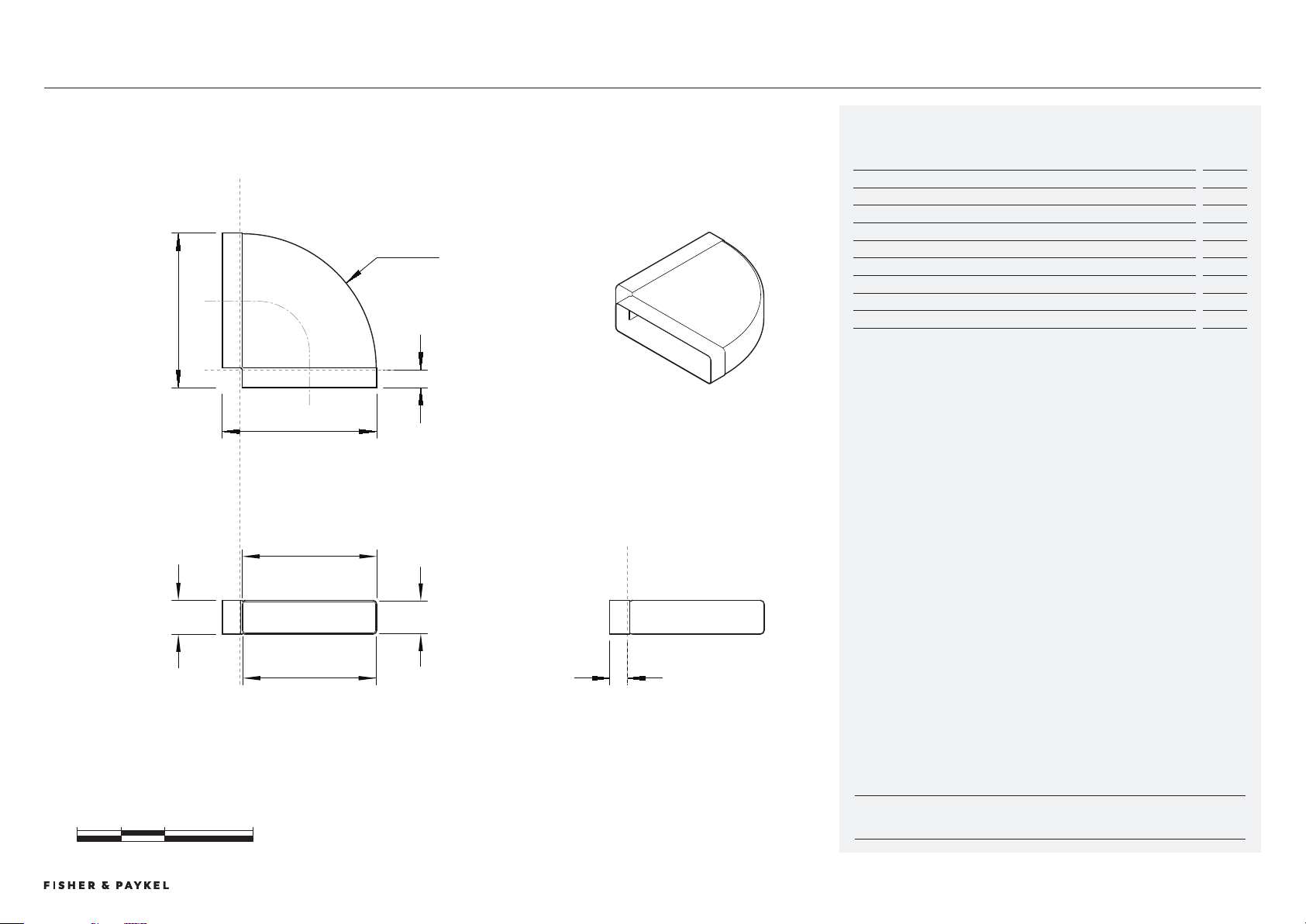
Optional Part no:
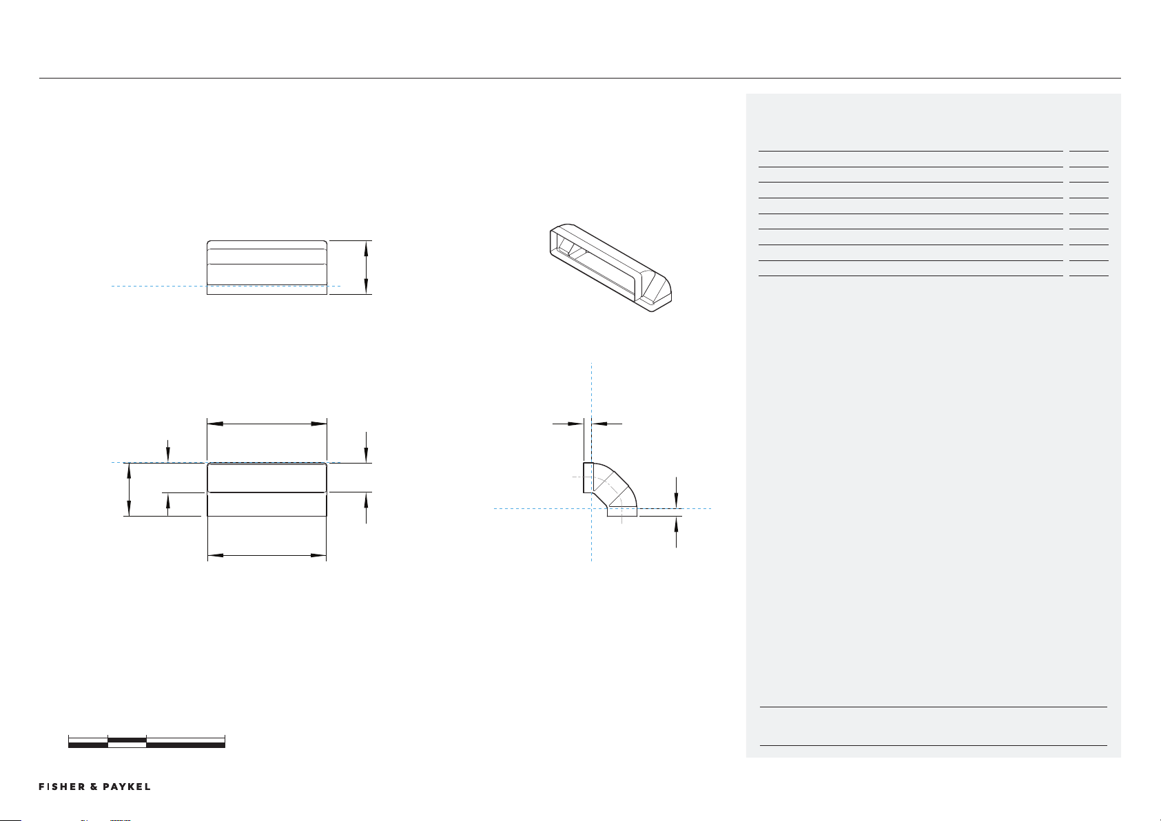
Horizontal Elbow, 90°- E90H300X70
Product Dimensions
mm
a Overall height of duct
77
B Overall width of duct
52
c Overall length of duct
52
d Internal height of female duct end
74
e Internal width of female duct end
04
f Internal shoulder depth of female duct end
40
G External width of female duct end
07
h Centre Radius of bend
05
Horizontal Elbow, 90
E90H00X70DATA SHEETS | MODULAR COOKTOPS
© FISHER & PAYKEL LIMITED 202 PAGE 219000269A PLANNING GUIDE MODULAR COOKTOPS VERSION 1 - AUGUST 202 © FISHER & PAYKEL LIMITED 202 PAGE 219000269A PLANNING GUIDE MODULAR COOKTOPS VERSION 1 - AUGUST 202
INDICATES CABINETRY / PRODUCT DATUM -------------------------
INDICATES CABINETRY CLEARANCES --------------------------------
INDICATES CUTOUT -------------------------------------------------------
IMPORTANT NOTE: Throughout this guide, dimensions may vary by ±2mm (1/16''). Please read
the installation manual for detailed information on installing the product. For full installation
instructions & specifications visit fisherpaykel.com
0 100 200 400
millimetres
c
dg
e
f
f
PROFILE VIEW
FRONT VIEW
PLAN VIEW
DATUM : DUCT INTERFACE
DATUM : DUCT INTERFACE
DATUM : DUCT INTERFACE
a
137
b
307
137
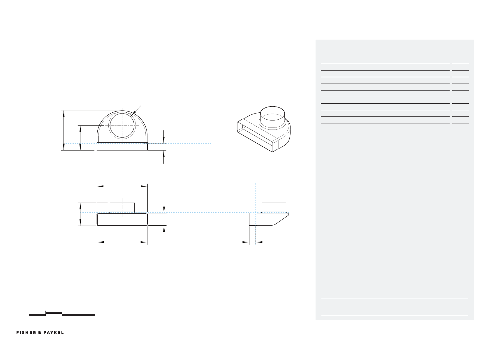
Optional Part no:
Vertical Elbow, 90° - E90V300X70
Product Dimensions
mm
a Overall height of ducting
17
B Overall width of ducting
07
c Overall depth of ducting
17
d Internal height of female duct end
74
e Internal width of female duct end
04
f Internal shoulder depth of female duct end
20
G External height of female duct end
74
Vertical Elbow, 90
E90V00X70DATA SHEETS | MODULAR COOKTOPS
© FISHER & PAYKEL LIMITED 202 PAGE 229000269A PLANNING GUIDE MODULAR COOKTOPS VERSION 1 - AUGUST 202 © FISHER & PAYKEL LIMITED 202 PAGE 229000269A PLANNING GUIDE MODULAR COOKTOPS VERSION 1 - AUGUST 202
INDICATES CABINETRY / PRODUCT DATUM -------------------------
INDICATES CABINETRY CLEARANCES --------------------------------
INDICATES CUTOUT -------------------------------------------------------
IMPORTANT NOTE: Throughout this guide, dimensions may vary by ±2mm (1/16''). Please read
the installation manual for detailed information on installing the product. For full installation
instructions & specifications visit fisherpaykel.com
0 100 200 400
millimetres
h
d
g
e
f
f
PROFILE VIEW
FRONT VIEW
PLAN VIEW
DATUM : DUCT INTERFACE
DATUM : DUCT INTERFACE
DATUM : DUCT INTERFACE
a
139
c
240
b
307
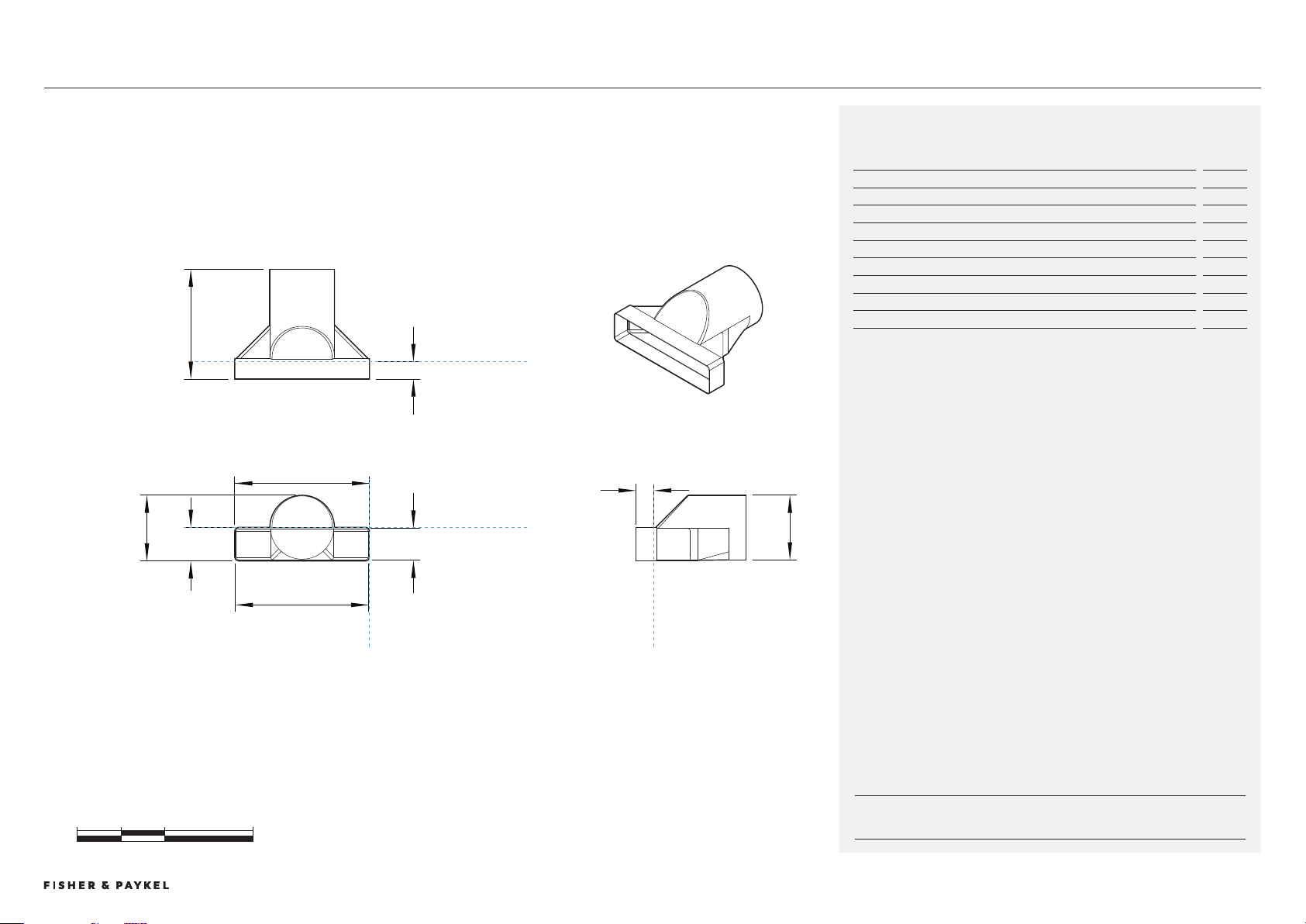
Optional Part no:
Duct Adapter, 150mm Diameter, 90° - DA300X70D150-90D
Product Dimensions
mm
a Overall height of adapter
19
B Overall width of adapter
07
c Overall length of adapter
240
d Internal height of female duct end
74
e Internal width of female duct end
04
f Internal depth of rectangular female duct end
40
G Internal diameter of round female duct end
147
h Height from bottom of adapter to centre of outlets
150
Duct Adapter, 90
DA00X70D150-90DDATA SHEETS | MODULAR COOKTOPS
© FISHER & PAYKEL LIMITED 202 PAGE 29000269A PLANNING GUIDE MODULAR COOKTOPS VERSION 1 - AUGUST 202 © FISHER & PAYKEL LIMITED 202 PAGE 29000269A PLANNING GUIDE MODULAR COOKTOPS VERSION 1 - AUGUST 202
INDICATES CABINETRY / PRODUCT DATUM -------------------------
INDICATES CABINETRY CLEARANCES --------------------------------
INDICATES CUTOUT -------------------------------------------------------
IMPORTANT NOTE: Throughout this guide, dimensions may vary by ±2mm (1/16''). Please read
the installation manual for detailed information on installing the product. For full installation
instructions & specifications visit fisherpaykel.com
0 100 200 400
millimetres
d
h
g
e
f
f
PROFILE VIEW
FRONT VIEW
PLAN VIEW
DATUM : DUCT INTERFACE
DATUM : DUCT INTERFACE
DATUM : DUCT INTERFACE DATUM : DUCT INTERFACE
a
150
b
307
c
250
Optional Part no:
Duct Adapter, 150mm Diameter - DA300X70D150
Product Dimensions
mm
a Overall height of adapter
150
B Overall width of adapter
07
c Overall length of adapter
250
d Internal height of rectangular female duct end
74
e Internal width of rectangular female duct end
04
f Internal depth of rectangular female duct end
40
G External height of rectangular female duct end
77
h External diameter of round duct female duct end
147
Duct Adapter, 150mm Diameter
DA00X70D150DATA SHEETS | MODULAR COOKTOPS
© FISHER & PAYKEL LIMITED 202 PAGE 249000269A PLANNING GUIDE MODULAR COOKTOPS VERSION 1 - AUGUST 202 © FISHER & PAYKEL LIMITED 202 PAGE 249000269A PLANNING GUIDE MODULAR COOKTOPS VERSION 1 - AUGUST 202
INDICATES CABINETRY / PRODUCT DATUM -------------------------
INDICATES CABINETRY CLEARANCES --------------------------------
INDICATES CUTOUT -------------------------------------------------------
IMPORTANT NOTE: Throughout this guide, dimensions may vary by ±2mm (1/16''). Please read
the installation manual for detailed information on installing the product. For full installation
instructions & specifications visit fisherpaykel.com
0 100 200 400
millimetres
c
d
g
e
f
PROFILE VIEW
FRONT VIEW
PLAN VIEW
DATUM : DUCT INTERFACE
DATUM : DUCT INTERFACE
DATUM : DUCT INTERFACE DATUM : DUCT INTERFACE
a
77
b
307
77
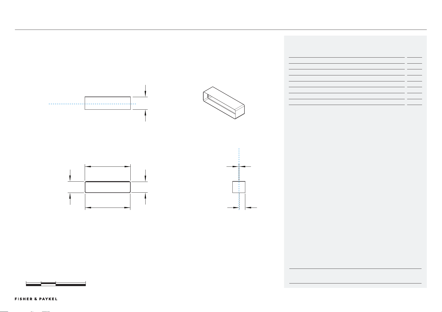
Optional Part no:
Connector - C300X70
Product Dimensions
mm
a Overall height of connector
77
B Overall width of connector
07
c Overall depth of connector
85
d Internal height of connector
74
e Internal width of connector
04
f Internal depth to shoulder
40
G Thickness of internal shoulder divider
5
Connector
C00X70DATA SHEETS | MODULAR COOKTOPS
© FISHER & PAYKEL LIMITED 202 PAGE 259000269A PLANNING GUIDE MODULAR COOKTOPS VERSION 1 - AUGUST 202 © FISHER & PAYKEL LIMITED 202 PAGE 259000269A PLANNING GUIDE MODULAR COOKTOPS VERSION 1 - AUGUST 202
INDICATES CABINETRY / PRODUCT DATUM -------------------------
INDICATES CABINETRY CLEARANCES --------------------------------
INDICATES CUTOUT -------------------------------------------------------
IMPORTANT NOTE: Throughout this guide, dimensions may vary by ±2mm (1/16''). Please read
the installation manual for detailed information on installing the product. For full installation
instructions & specifications visit fisherpaykel.com
0 100 200 400
millimetres
a
d
c
FRONT VIEW
PLAN VIEW
1000
73
b
303
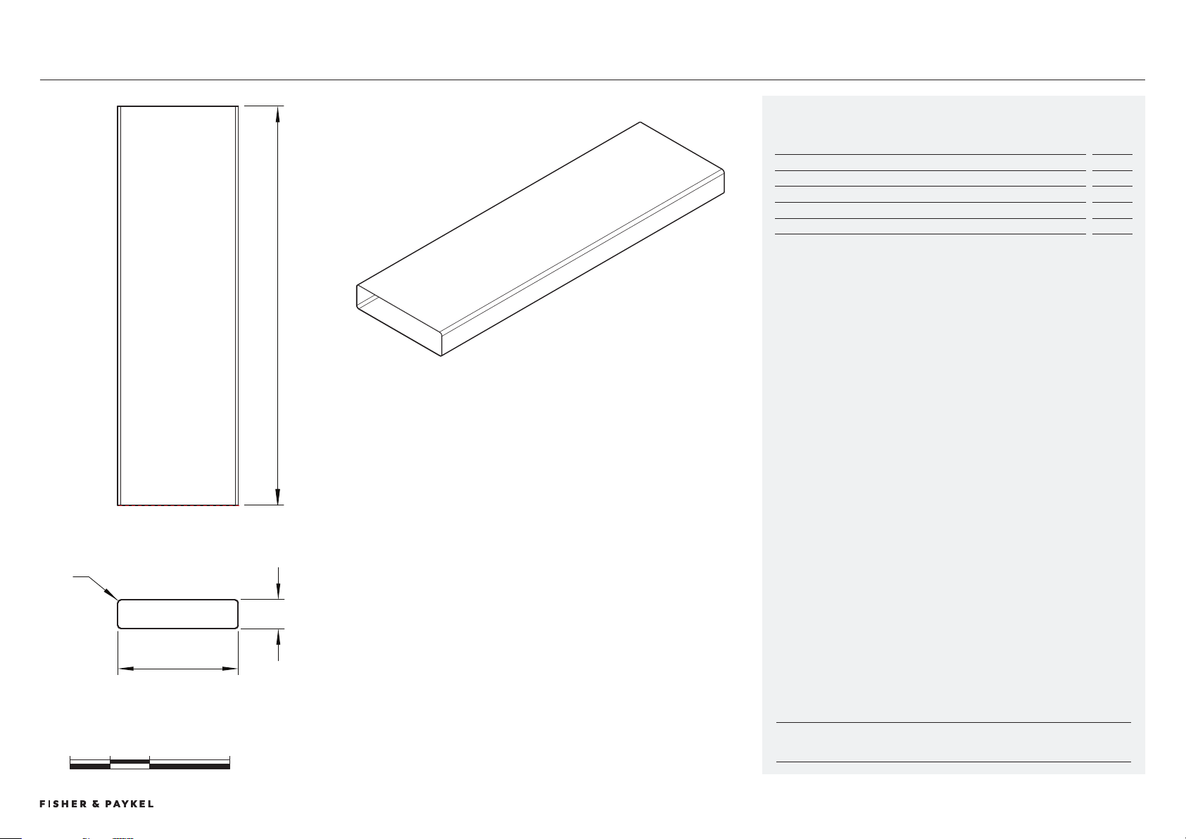
Optional Part no:
Duct, 1m - D1300X70
Product Dimensions
mm
a Overall height of ducting
7
B Overall width of ducting
0
c Overall length of ducting
1000
d Corner radius of ducting
9
Straight Ducting
D100X70DATA SHEETS | MODULAR COOKTOPS
© FISHER & PAYKEL LIMITED 202 PAGE 269000269A PLANNING GUIDE MODULAR COOKTOPS VERSION 1 - AUGUST 202 © FISHER & PAYKEL LIMITED 202 PAGE 269000269A PLANNING GUIDE MODULAR COOKTOPS VERSION 1 - AUGUST 202
INDICATES CABINETRY / PRODUCT DATUM -------------------------
INDICATES CABINETRY CLEARANCES --------------------------------
INDICATES CUTOUT -------------------------------------------------------
IMPORTANT NOTE: Throughout this guide, dimensions may vary by ±2mm (1/16''). Please read
the installation manual for detailed information on installing the product. For full installation
instructions & specifications visit fisherpaykel.com
Recirculation Kit
KRCID84DATA SHEETS | MODULAR COOKTOPS
Optional Accessory Model no:
Recirculation Kit - KRCID84
Component Description
Quanitity
Filter Box Assembly
x2
Duct Adapter
x4
Cap
x4
m Flexible Ducting
x1
Product Dimensions
mm
a Overall height of filter box assembly (louvres can be trimmed to
suit kickstrip)
150/10/115/100
B Overall width of filter box assembly
62
c Overall depth of filter box assembly
54
D Height of filter box
98
e Width of filter box at front
46
f Width of filter box at rear
256
G Depth of filter box (excludes bracket)
51
h Depth of bracket flange
1
i Depth of bracket and louvres
26
j Height from bottom of filter box to centre of outlets
49
k Depth from rear of filter box to centre of side outlets
128
l Height from bottom of bracket to lower hole centre
19
m Height between hole centres
60
n Depth from rear of bracket flange to hole centre
7
o Hole diameter
4
p Width of louvres
2
Kickstrip Dimensions
mm
Height of kickstrip (louvres trimmed to suit)
150/10/115/100
Overall width of cutout
47
FRONT VIEW
PLAN VIEW
PROFILE VIEW
G
k
f
D
i
e
C
A
B
h
jl
m
p
n
DATUM : FRONT OF KICKSTRIP
DATUM : FRONT OF KICKSTRIP
CLEARANCE : KICKSTRIP CUTOUT
CLEARANCE : MINIMUM KICK HEIGHT
CLEARANCE :
OPTIONAL KICK HEIGHTS
EXPLODED ISOMETRIC VIEW
DUCT ADAPTER
FLEXIBLE DUCTING
CAP
FILTERBOX ASSEMBLY
IMPORTANT NOTE
If specifying Recirculation Kit KRCID834
you will also require the Blower Outlet
Adaptor OAB222X89
© FISHER & PAYKEL LIMITED 202 PAGE 279000269A PLANNING GUIDE MODULAR COOKTOPS VERSION 1 - AUGUST 202 © FISHER & PAYKEL LIMITED 202 PAGE 279000269A PLANNING GUIDE MODULAR COOKTOPS VERSION 1 - AUGUST 202
INDICATES CABINETRY / PRODUCT DATUM -------------------------
INDICATES CABINETRY CLEARANCES --------------------------------
INDICATES CUTOUT -------------------------------------------------------
IMPORTANT NOTE: Throughout this guide, dimensions may vary by ±2mm (1/16''). Please read
the installation manual for detailed information on installing the product. For full installation
instructions & specifications visit fisherpaykel.com
qu
sv t
CAP (x2)
FILTER BOX ASSEMBLY (x1)
DUCT ADAPTER (x2)
Adapter can be connected to
Flexible Ducting 227 x 94
or
Straight Ducting 222 x 89
PLAN VIEW
EXPLODED ISOMETRIC VIEW
FILTER BOX ASSEMBLY WITH DUCT ADAPTER AND CAPS - x2 SETS SUPPLIED
Position of caps and adapters can be interchanged to suit ducting layout
r
DATUM : DUCT INTERFACE
DATUM : DUCT INTERFACE
Optional Accessory Model no:
Recirculation Kit - KRCID84
Product Dimensions
mm
q Distance from edge of duct adapter to edge of filter box
46
r Internal depth of female end of duct adapter
4
s Overall length of duct adapter
227
t Internal length of female end of duct adapter
22
Overall height of duct adapter (not shown)
94
Internal height of female end of duct adapter (not shown)
90
u Thickness of cap from edge of filter box
2
v Length of cap
226
Height of cap (not shown)
9
Kickstrip Dimensions
mm
Height of kickstrip (louvres trimmed to suit)
150/10/115/100
Overall width of cutout
47
KRCID84DATA SHEETS | MODULAR COOKTOPS
BRACKET LOUVRES
EXPLODED PROFILE VIEW
BRACKET + LOUVRES
DATUM : FLOOR
EXPLODED ISO VIEW
FILTER BOX, BRACKETS
+ LOUVRES
FILTER BOX
DATUM : OPTIONAL
KICK HEIGHTS
h
100
j
115
l
10
n
150

© FISHER & PAYKEL LIMITED 202 PAGE 289000269A PLANNING GUIDE MODULAR COOKTOPS - VERSION 1 - AUGUST 202
PRODUCT DECISIONS
© FISHER & PAYKEL LIMITED 202 PAGE 299000269A PLANNING GUIDE MODULAR COOKTOPS VERSION 1 - AUGUST 202
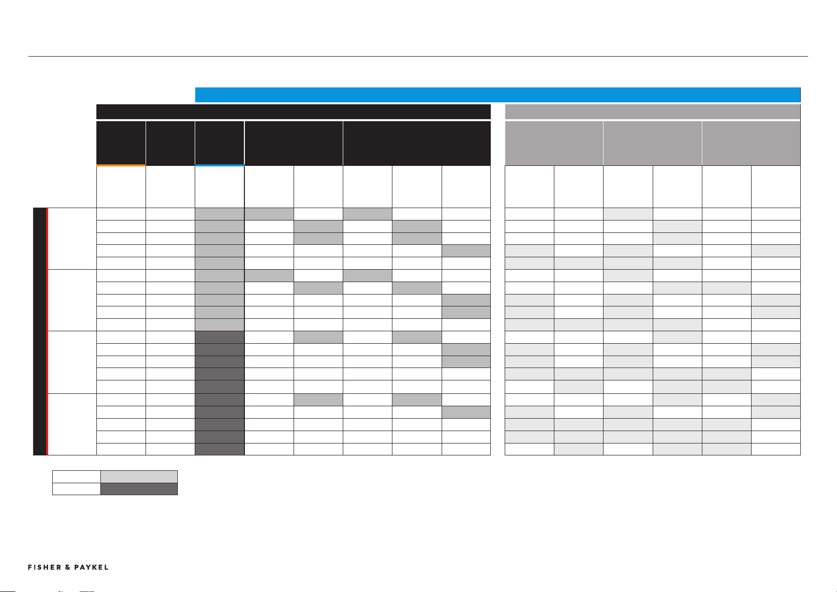
PAIRING GUIDE
Available
not suitable downdraft not sufficient
#
Can not combine downdraft with rangehood units
* not possible connect 2 overhead ventilation units with a primary cooktop
+ 2 different rangehood widths need to be combined
** One rangehood could be connected, the second would have to be manually operated.
VENTILATION CHOICE - DOWNDRAFT OR INSERT RANGEHOOD OR WALL RANGEHOOD
#
CONNECTED * NOT CONNECTED
AUXILIARY
COOKTOP
0-2
COMBINED
COOKTOP
WIDTH
AUXILIARY
DOWNDRAFT
VENTILATION
1-2
INSERT RANGEHOOD
x1
WALL RANGEHOOD
x1
INSERT RANGEHOOD**
glass
INSERT RANGEHOOD
shallow
stainless
INSERT RANGEHOOD
deep
stainless
MODELS
CI02D
CIT02DX1
CI92D
CI92DX1
DOWNDRAFT
CD1D
Recirculation
option
60cm
HP60IDCHX4
HP60IDCHEX4
90cm
HP90IDCHX4
HP90IDCHEX4
60cm
HC60DCXB4
90cm
HC90DCXB4
HC90DCBB4
HC90DCEBB4
HC90DCEXB4
120cm
HC120DCXB4
60cm
HP60IDCHX4
HP60IDCHEX4
90cm
HP90IDCHX4
HP90IDCHEX4
60cm
HPB6028-1
90cm
HPB9028-1
90cm
HPB9048-2
120cm
HPB12048-2
PRIMARY COOKTOP x1
9 CM x0 9cm 1 1 1 1
CI92DTT x1 0cm 69cm 1 1 1 1
x1 9cm 78cm 1 1 1 1
x2 0cm 99cm 2 1 2 2 1
x2 9cm 127cm 2 1 1 1 1
60 CM x0 60cm 2 1 1 1
CI604DTT x1 0cm 90cm 2 1 1 1 1
x1 9cm 99cm 2 1 2 2 1
x2 0cm 120cm 2 1 2 2 1
x2 9cm 18cm 2 1 1 1 1
76 cm x0 76cm - 1 1 1
CI764DTT x1 0cm 106cm - 1 2 2 1
x1 9cm 115cm - 1 2 2 1
x2 0cm 16cm - 1 1 1 1 2
x2 9cm 154cm - 2 2 2
90 cm x0 90cm - 1 1 1 1
CI905DTT x1 0cm 120cm - 1 2 2 1
x1 9cm 129cm - 1 1 1 1 2
x2 0cm 150cm - 1 1 1 1 2
x2 9cm 168cm - 2 2 2
+
+
+
+
+
+
+
+
+
+
Pairing Guide
PRODUCT DECISIONS | MODULAR COOKTOPS
© FISHER & PAYKEL LIMITED 202 PAGE 09000269A PLANNING GUIDE MODULAR COOKTOPS VERSION 1 - AUGUST 202
MODULAR SYSTEM CAPABILITIES
PRIMARY COOKTOP
Touchscreen user interface.
Controls complete modular suite.
Available in 39cm, 60cm, 76cm and 90cm widths.
AUXILIARY COOKTOP
No user interface.
Must be paired with a primary cooktop.
Controlled by the primary cooktop.
Available in 30cm and 39cm widths.
AUXILIARY VENTILATION
Downdraft has no user interface and must be paired
with and controlled by the primary cooktop.
Overhead can be controlled by the primary cooktop.
+
_
+
_
CONNECTED EXPERIENCE
INDUCTION INDUCTION
TEPPANYAKI DOWNDRAFT
OVERHEAD
MIX AND MATCH EITHER OR
ESSENTIAL
1x MAXIMUM
RECOMMENDED
OVERHEAD 1x
DOWNDRAFT 1-2x
OPTIONAL
0-2x
Modular System Capabilities
PRODUCT DECISIONS | MODULAR COOKTOPS
© FISHER & PAYKEL LIMITED 202 PAGE 19000269A PLANNING GUIDE MODULAR COOKTOPS VERSION 1 - AUGUST 202
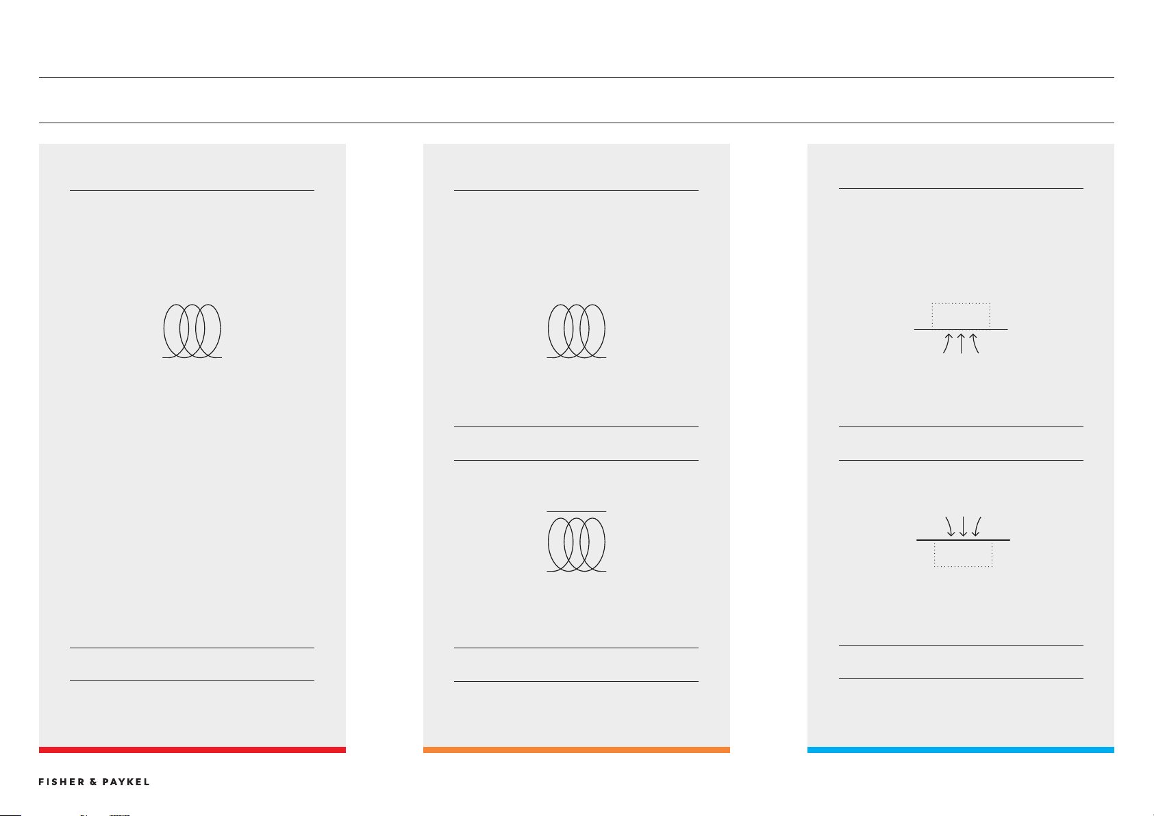
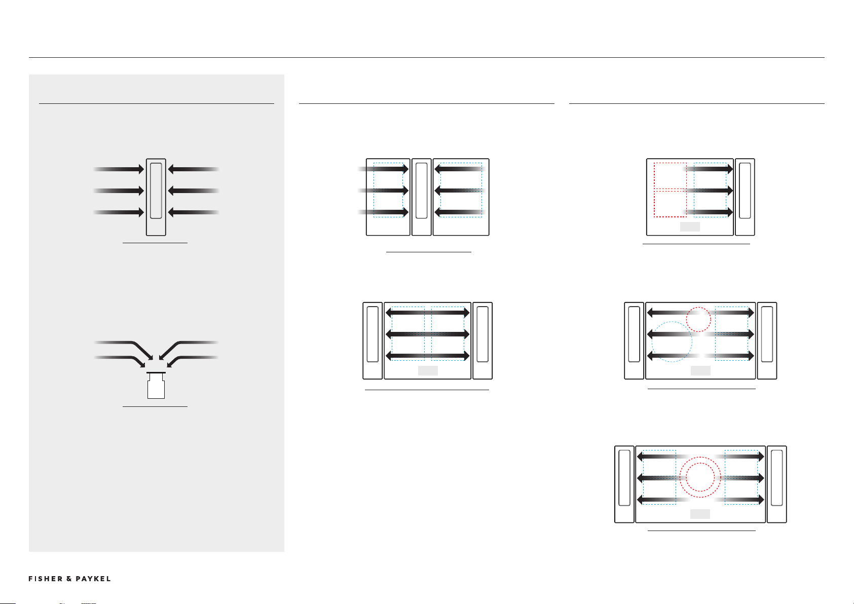
DOWNDRAFT VENTILATION
The modular ventilation unit is a downdraft ventilation system that
efficiently extracts air across and downwards.
The modular ventilation unit provides efficient ventilation to adjacent
cookzones. Consideration of cookzone layout is critical for optimum
pairing of ventilation type and quantity along with cook module size.
IMPORTANT: Where modular ventilation is unable to provide efficient
venting it is recommended that overhead extraction is chosen.
WARNING: The Modular Ventilation unit can not be used alongside a
gas cooktop.
MODULAR VENTILATION CAPABILITIES
SUFFICIENT VENTILATION
ADJACENT COOKZONES EFFECTIVELY VENTED
INSUFFICIENT VENTILATION
NON-ADJACENT COOKZONES ARE NOT SUFFICIENTLY VENTED
00 + 90 MODULES
600 MODULE WITH 2x DOWNDRAFT
600 MODULE WITH 1x DOWNDRAFT
760 MODULE WITH 2x DOWNDRAFT
900 MODULE WITH 2x DOWNDRAFT
TOP VIEW
FRONT VIEW
Modular Ventilation Capabilites
PRODUCT DECISIONS | MODULAR COOKTOPS
© FISHER & PAYKEL LIMITED 202 PAGE 29000269A PLANNING GUIDE MODULAR COOKTOPS VERSION 1 - AUGUST 202
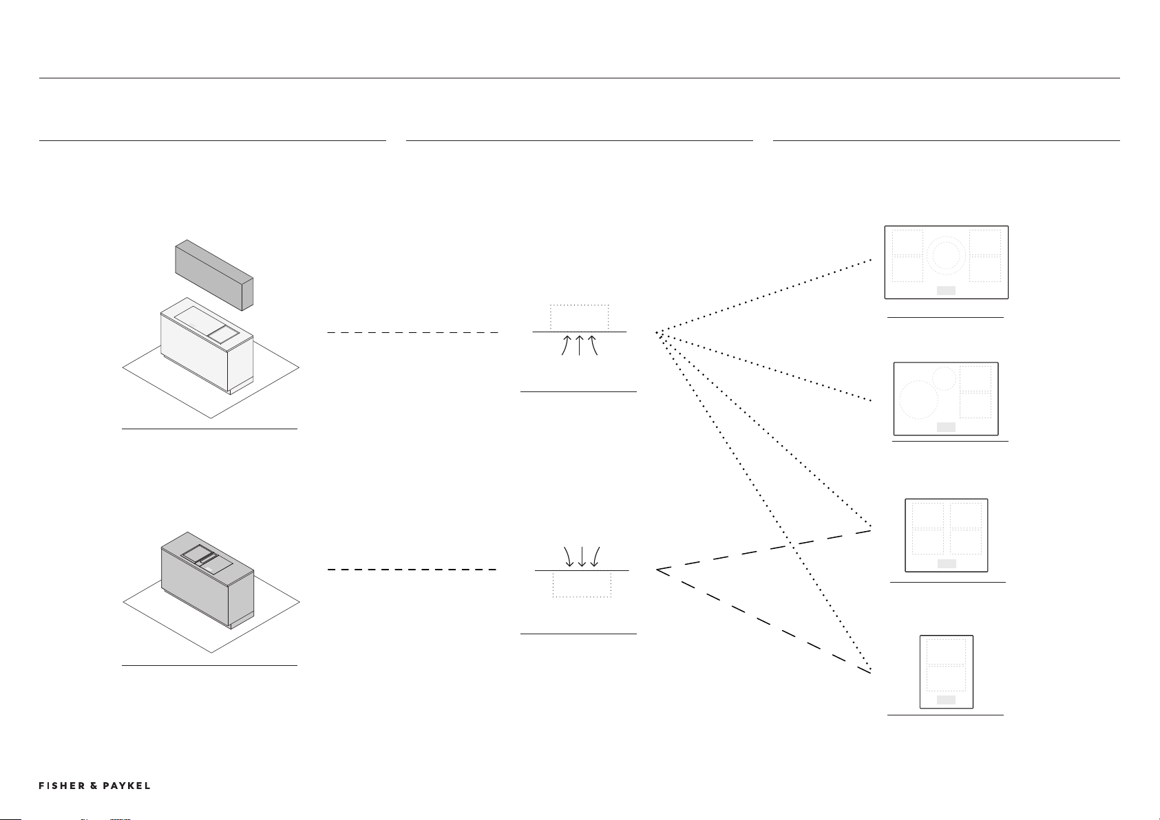
VENTILATION CHOICE
VENTILATION TYPE PRIMARY COOKTOP
PAIRED FOR OPTIMUM VENTILATION
CHOICE DETERMINED BY VENTILATION CAPABILITIES
VISUAL POSITION
VENTILATION POSITION
90CM PRIMARY
76CM PRIMARY
60CM PRIMARY
2x Downdraft
9CM PRIMARY
1x Downdraft
DOWNDRAFT
OVERHEAD
VISUAL ELEMENT ABOVE COOKSURFACES
NO VISUAL ELEMENT ABOVE COOKSURFACES
Ventilation Choice
PRODUCT DECISIONS | MODULAR COOKTOPS

© FISHER & PAYKEL LIMITED 202 PAGE 9000269A PLANNING GUIDE MODULAR COOKTOPS - VERSION 1 - AUGUST 202
PLANNING CONSIDERATIONS
© FISHER & PAYKEL LIMITED 202 PAGE 49000269A PLANNING GUIDE MODULAR COOKTOPS VERSION 1 - AUGUST 202 © FISHER & PAYKEL LIMITED 202 PAGE 49000269A PLANNING GUIDE MODULAR COOKTOPS VERSION 1 - AUGUST 202
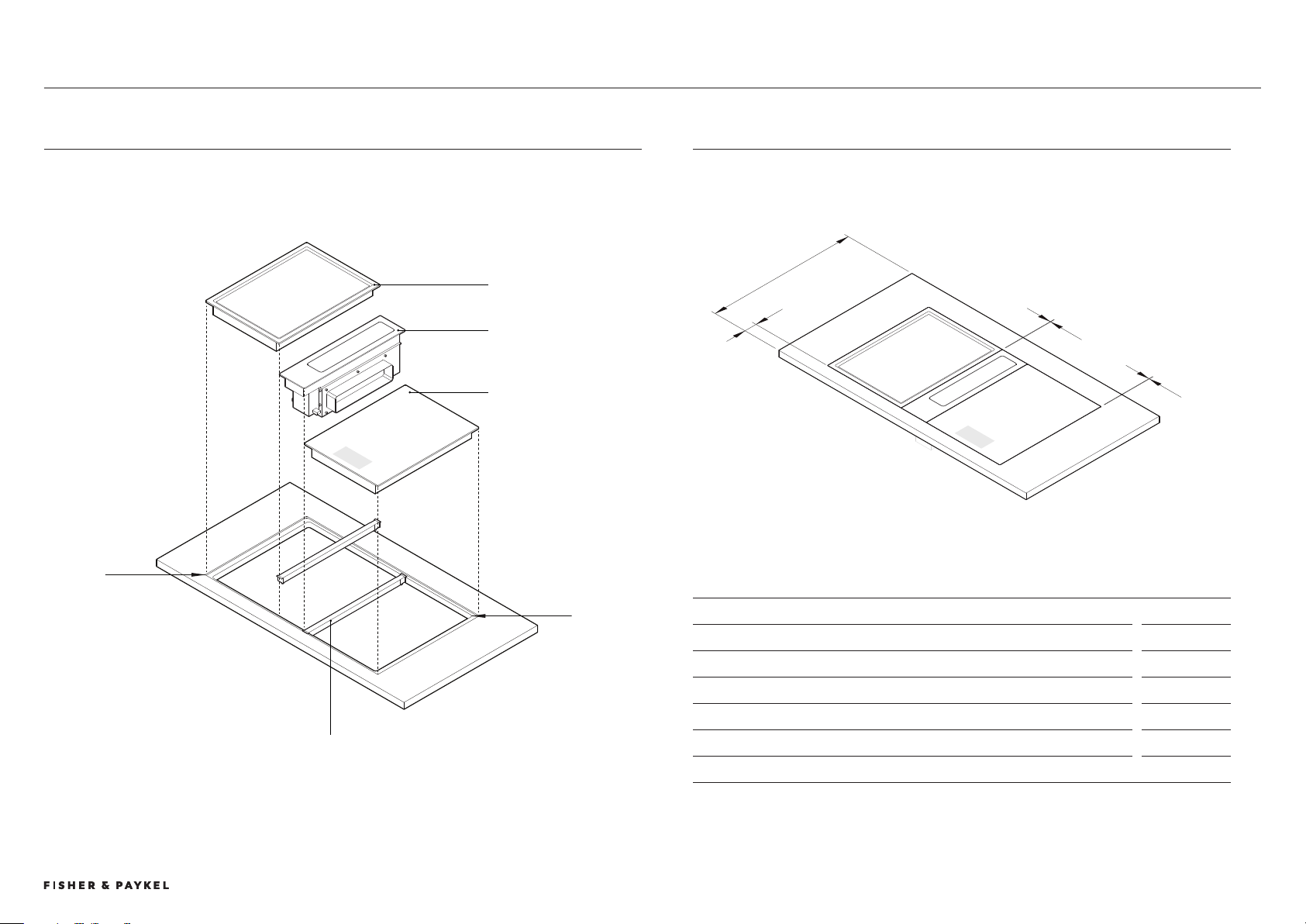
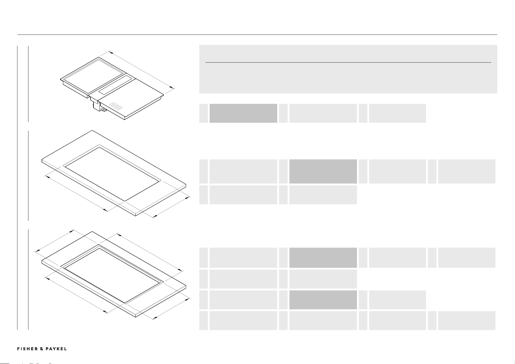
INSTALLATION DIMENSIONS
PRODUCT DIMENSIONS
mm
A Nominal bench depth* min 700
B Nominal distance from front of bench to front of cooktop 60
C Distance between modules 2
D Distance between edge of module and edge of recess 2
E Corner radii of cutout max 10
F Corner radii of recess 4
* Based on nominal distance 'B', where cabinetry constructed from 19mm panels and ducting routes to rear of
cabinet. Can be reduced to 600, see page 20 for details.
INSTALLATION OVERVIEW
INSTALLATION OVERVIEW
a
b
c
d
E
f
JOINER BAR
Required between
modules, supplied.
PRIMARY COOKTOP
AUXILIARY VENTILATION
AUXILIARY COOKTOP
Installation Overview
PLANNING CONSIDERATIONS | MODULAR COOKTOPS
© FISHER & PAYKEL LIMITED 202 PAGE 59000269A PLANNING GUIDE MODULAR COOKTOPS VERSION 1 - AUGUST 202
COMBINED INSTALLATION OVERVIEW
A
e
d
c
b
F
b
A
OVERALL WIDTH OF MODULES = COMBINED PRODUCT WIDTHS
add module widths
+ GAPS BETWEEN MODULES
2mm x (number of modules -1)
b
WIDTH OF CUTOUT
FLUSH AND PROUD
= OVERALL WIDTH OF MODULES - LEFT OVERHANG
19mm Induction / Teppanyaki OR
17mm Downdraft
- RIGHT OVERHANG
19mm Induction / Teppanyaki OR
17mm Downdraft
c
DEPTH OF CUTOUT
PROUD
= 507MM
b
WIDTH OF CUTOUT
FLUSH AND PROUD
= OVERALL WIDTH OF MODULES - LEFT OVERHANG
19mm Induction / Teppanyaki OR
17mm Downdraft
- RIGHT OVERHANG
19mm Induction / Teppanyaki OR
17mm Downdraft
d
DEPTH OF CUTOUT
FLUSH
= 509mm
e
WIDTH OF RECESS
FLUSH
= OVERALL WIDTH OF MODULES + 4mm
2mm each side
f
DEPTH OF RECESS
FLUSH
= 54mm = 50mm
product depth
+ 4mm
2mm top and bottom
COMBINED BENCHTOP EQUATIONS
Pairings of modular products have been designed to fit in a singular benchtop cutout. When grouping modules it is essential to calculate their
combined cutout requirements. The following equations can be used to guide calculations.
For dimensions of common configurations please refer to subsequent pages.
FLUSH PROUD MODULES
Combined Installation
PLANNING CONSIDERATIONS | MODULAR COOKTOPS
© FISHER & PAYKEL LIMITED 202 PAGE 69000269A PLANNING GUIDE MODULAR COOKTOPS VERSION 1 - AUGUST 202 © FISHER & PAYKEL LIMITED 202 PAGE 69000269A PLANNING GUIDE MODULAR COOKTOPS VERSION 1 - AUGUST 202
TYPICAL CONFIGURATIONS WITH MODULAR VENTILATION
5 TRIPLE WITH MODULAR VENTILATION
Dimensions
W x D x H
Combined Module Size
1468 x 50 x 180
Recess, flush 1472 x 54 x 6.5
Cutout, flush 140 x 509
Cutout, proud 140 x 507
1 SINGLE WITH MODULAR VENTILATION
Dimensions
W x D x H
Combined Module Size
517 x 50 x 180
Recess, flush
521 x 54 x 6.5
Cutout, flush*
479 x 509
Cutout, proud*
479 x 507
*Cutout width not central to overall width of modules. Offset
specific to placement of downdraft unit to the left or right. Side
overhangs differ for downdraft and cooktop - downdraft 17mm,
cooktops 19mm. Refer 'Benchtop Installation Details' for more
information.
9cm
4 TRIPLE WITH MODULAR VENTILATION
Dimensions
W x D x H
Combined Module Size
142 x 50 x 180
Recess, flush
1427 x 54 x 6.5
Cutout, flush
185 x 509
Cutout, proud
185 x 507
3 TRIPLE WITH MODULAR VENTILATION
Dimensions
W x D x H
Combined Module Size
125 x 50 x 180
Recess, flush
1257 x 54 x 6.5
Cutout, flush
1215 x 509
Cutout, proud
1215 x 507
3
4
5
600
2 DOUBLE WITH MODULAR VENTILATION
Dimensions
W x D x H
Combined Module Size
904 x 50 x 180
Recess, flush
908 x 54 x 6.5
Cutout, flush*
862 x 509
Cutout, proud*
862 x 507
*Glass overhang at sides adjusted to fit 900mm cabinet. Dimensions
specific to 900 cabinet constructed from 19mm panels. 866W
cutout recommended if cabinetry construction allows.
6 TRIPLE WITH MODULAR VENTILATION
Dimensions
W x D x H
Combined Module Size
168 x 50 x 180
Recess, flush 1642 x 54 x 6.5
Cutout, flush 1600 x 509
Cutout, proud 1600 x 507
1 2
6
600 600600 600 600
900
600
9cm9cm 0cm 9cm 0cm
9cm 9cm 9cm
0cm 60cm 0cm
9cm 60cm 9cm
SINGLE - COMPACT <600
TWO IN A ROW - MID 900
THREE IN A ROW - WIDE >1200
THREE IN A ROW - EXTRA WIDE >1450
IMPORTANT NOTE
Other configurations are possible.
Cutout widths may not be possible in certain benchtop materials. Please refer to benchtop
suppliers recommendations for material parameters and fabrication recommendations.
PRIMARY COOKTOP
AUXILIARY COOKTOP
AUXILIARY VENTILATION
Typical Configurations with Modular Ventilation
PLANNING CONSIDERATIONS | MODULAR COOKTOPS

© FISHER & PAYKEL LIMITED 202 PAGE 79000269A PLANNING GUIDE MODULAR COOKTOPS VERSION 1 - AUGUST 202
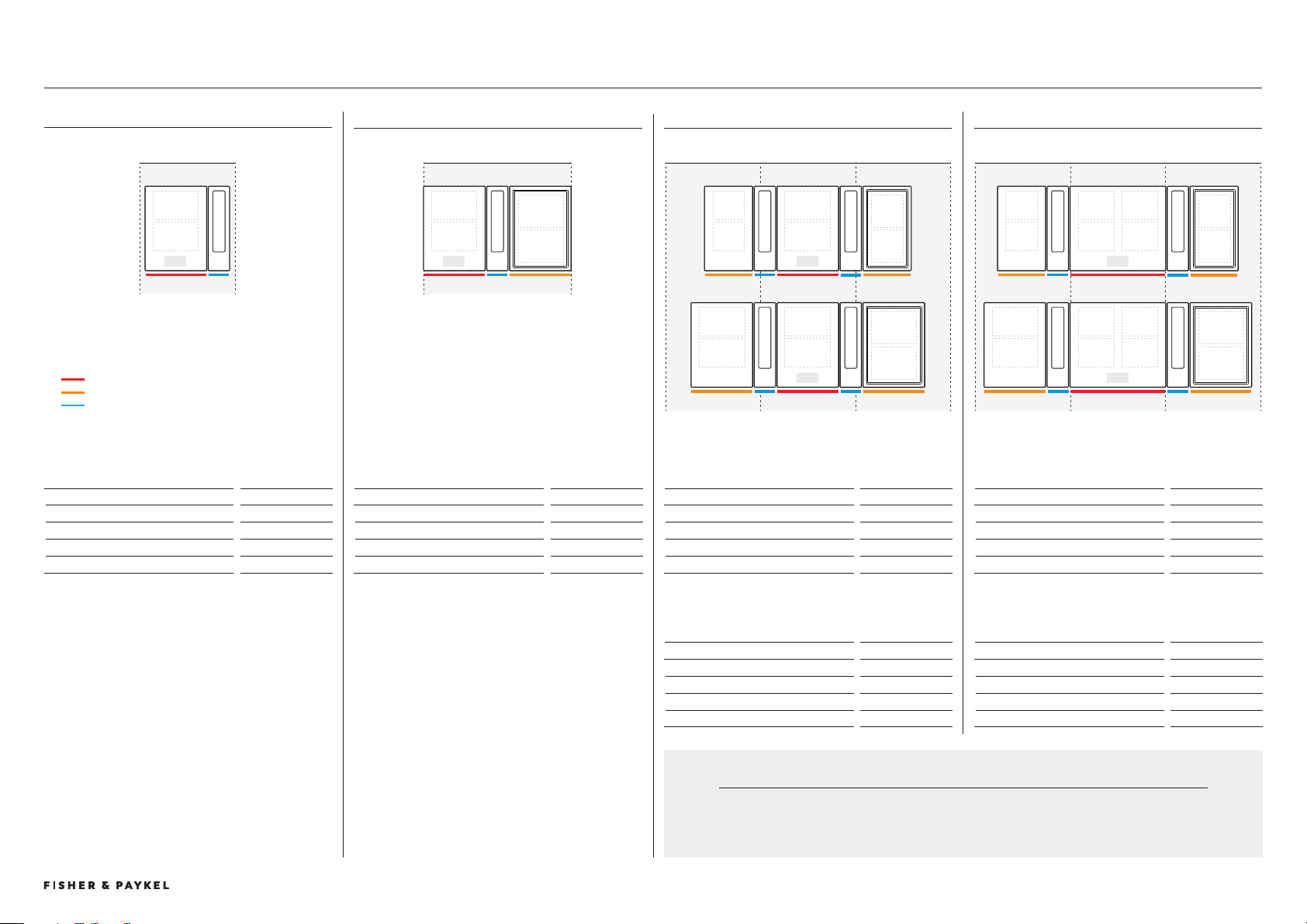
TYPICAL CONFIGURATIONS WITH OVERHEAD VENTILATION
1 SINGLE WITH MODULAR VENTILATION
Dimensions
W x D x H
Combined Module Size
772 x 50 x 58
Recess, flush
776 x 54 x 6.5
Cutout, flush
74 x 509
Cutout, proud
74 x 507
2 SINGLE WITH MODULAR VENTILATION
Dimensions
W x D x H
Combined Module Size
902 x 50 x 58
Recess, flush
906 x 54 x 6.5
Cutout, flush *
862 x 509
Cutout, proud *
862 x 507
*Glass overhang at sides adjusted to fit 900mm
cabinet. Dimensions specific to 900 cabinet.
864W cutout ideal
5 SINGLE WITH MODULAR VENTILATION
Dimensions
W x D x H
Combined Module Size
1147 x 50 x 58
Recess, flush
1151 x 54 x 6.5
Cutout, flush
1109 x 509
Cutout, proud
1109 x 507
3 SINGLE WITH MODULAR VENTILATION
Dimensions
W x D x H
Combined Module Size
67 x 50 x 58
Recess, flush 641 x 54 x 6.5
Cutout, flush 599 x 509
Cutout, proud 599 x 507
4 SINGLE WITH MODULAR VENTILATION
Dimensions
W x D x H
Combined Module Size
1062 x 50 x 58
Recess, flush
1066 x 54 x 6.5
Cutout, flush 1024 x 509
Cutout, proud 1024 x 507
6 SINGLE WITH MODULAR VENTILATION
Dimensions
W x D x H
Combined Module Size
1202 x 50 x 58
Recess, flush
1206 x 54 x 6.5
Cutout, flush
1168 x 509
Cutout, proud
1168 x 507
7 SINGLE WITH MODULAR VENTILATION
Dimensions
W x D x H
Combined Module Size
1204 x 50 x 58
Recess, flush
1208 x 54 x 6.5
Cutout, flush
1170 x 509
Cutout, proud
1170 x 507
9 SINGLE WITH MODULAR VENTILATION
Dimensions
W x D x H
Combined Module Size
164 x 50 x 58
Recess, flush
168 x 54 x 6.5
Cutout, flush
126 x 509
Cutout, proud
126 x 507
8 SINGLE WITH MODULAR VENTILATION
Dimensions
W x D x H
Combined Module Size
1287 x 50 x 58
Recess, flush
1291 x 54 x 6.5
Cutout, flush
125 x 509
Cutout, proud
125 x 507
"1 SINGLE WITH MODULAR VENTILATION
Dimensions
W x D x H
Combined Module Size
1504 x 50 x 58
Recess, flush
1508 x 54 x 6.5
Cutout, flush
1466 x 509
Cutout, proud
1466 x 507
"0 SINGLE WITH MODULAR VENTILATION
Dimensions
W x D x H
Combined Module Size
174 x 50 x 58
Recess, flush
178 x 54 x 6.5
Cutout, flush
16 x 509
Cutout, proud
16 x 507
600 600
900 600 600
760 760
760 760
6
7
8
1 3
94
5
2
"0
"1
60cm 9cm9cm 9cm
60cm 0cm 76cm 0cm
76cm 9cm
60cm 0cm 0cm
90cm 0cm
76cm 0cm
90cm
0cm
9cm 60cm 9cm 9cm
0cm 0cm
90cm
MID <900 WIDE <1200
EXTRA WIDE >1200
IMPORTANT NOTE
Other configurations are possible.
Cutout widths may not be possible in certain benchtop materials. Please refer to benchtop
suppliers recommendations for material parameters and fabrication recommendations.
PRIMARY COOKTOP
AUXILIARY COOKTOP
Typical Configurations with Overhead Ventilation
PLANNING CONSIDERATIONS | MODULAR COOKTOPS
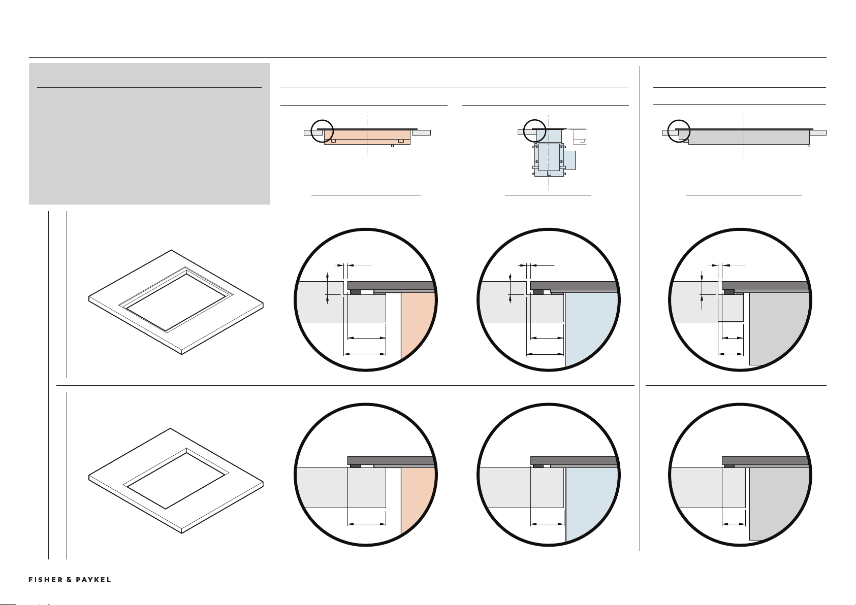
© FISHER & PAYKEL LIMITED 202 PAGE 89000269A PLANNING GUIDE MODULAR COOKTOPS VERSION 1 - AUGUST 202
17mm
19mm
BENCHTOP INSTALLATION DETAILS
2mm
6.5mm
17mm
19mm
2mm
6.5mm
19mm
21mm
10.5mm
12.5mm
2mm
6.5mm
11.5mm
FRONT VIEW PROFILE VIEW FRONT VIEW
SIDE OVERHANGS
INDUCTION + TEPPANYAKI MODULES DOWNDRAFT MODULE
FRONT + REAR OVERHANG
ALL MODULES
BENCH DETAIL
PROUD FLUSH
BENCHTOP INSTALLATION
A flush or proud finish between the top surface of the modules
and benchtop is achievable.
Some overhang details are common left to right or front to back,
however there are small dimensional changes between proud and
flush, cooking modules and ventilation module.
Care needs to be taken during planning and fabrication to ensure
successful installation of modules
Benchtop Details
PLANNING CONSIDERATIONS | MODULAR COOKTOPS
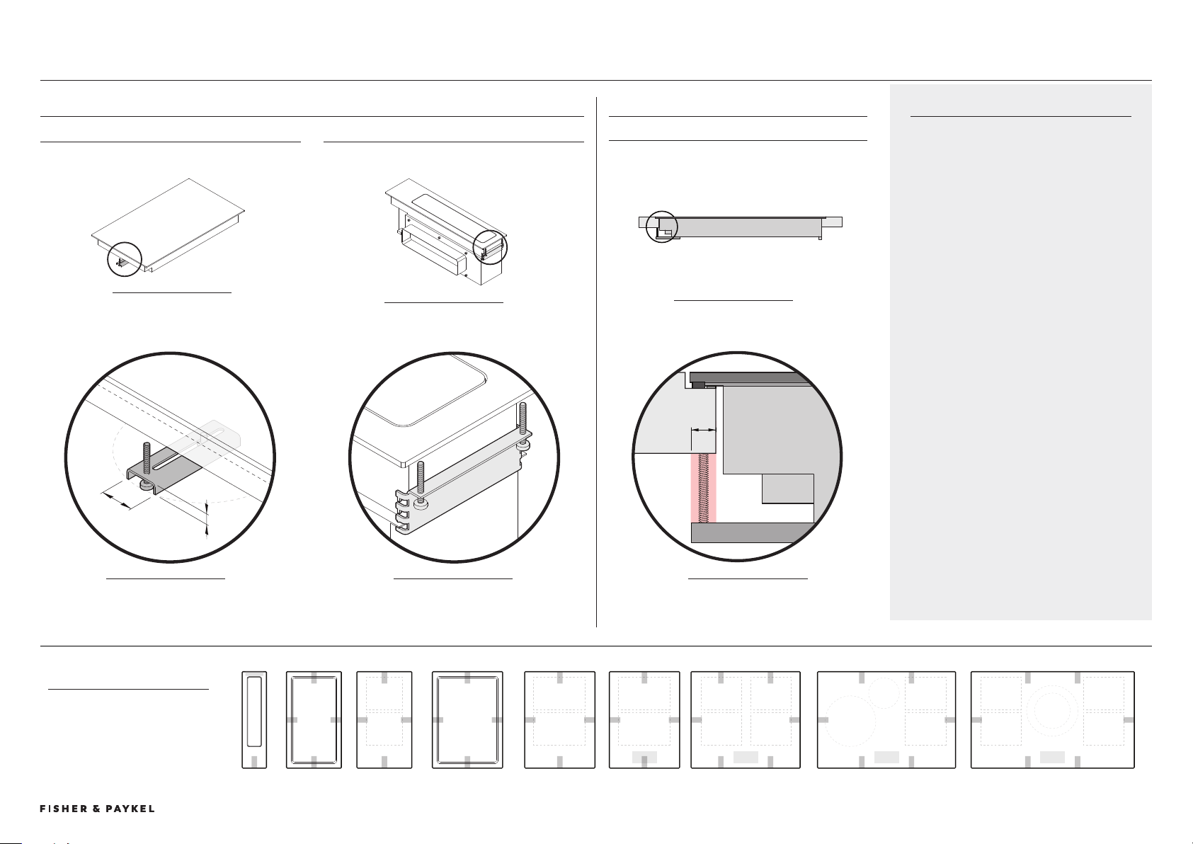
© FISHER & PAYKEL LIMITED 202 PAGE 99000269A PLANNING GUIDE MODULAR COOKTOPS VERSION 1 - AUGUST 202 © FISHER & PAYKEL LIMITED 202 PAGE 99000269A PLANNING GUIDE MODULAR COOKTOPS VERSION 1 - AUGUST 202
CLAMPS
Clamps are suplied with modules to secure
their postition to benchtop. There are two
types, common and rear downdraft.
It is recommended to have 10mm clearance
from edge of cutout for clamp engagement..
Clamps are attached to chassis at fixed hole
locations. A minimum of 2 clamps are required
per module, it is recommended they are
positioned on opposite sides of each module
eg. left and right or front and rear.
For more details please refer to Install Guide.
CLAMP FIXING LOCATIONS
PLAN VIEW
Minimum of 2 clamps per
module. For specific locations
please refer to data sheets.
DETAIL A
Can be rotated and
moved horizontally
ISO FRONT VIEW
ISO REAR VIEW
SIDE VIEW
CLEARANCE REQUIREMENTS
ALL MODULES
BRACKET TYPES
COMMON BRACKET REAR DOWNDRAFT BRACKET
Applies to all bracket locations, exluding rear downdraft
10mm
25mm
10mm
9cm 60cm0cm 76cm 90cm9cm 9cm0cm
DETAIL B
Bracket can be be
repositioned vertically
A
B
C
DETAIL C
Minimum clearance
common to all brackets
left/right amd font/rear
PLANNING CONSIDERATIONS | MODULAR COOKTOPS CLAMPING LOCATIONS
© FISHER & PAYKEL LIMITED 202 PAGE 409000269A PLANNING GUIDE MODULAR COOKTOPS VERSION 1 - AUGUST 202
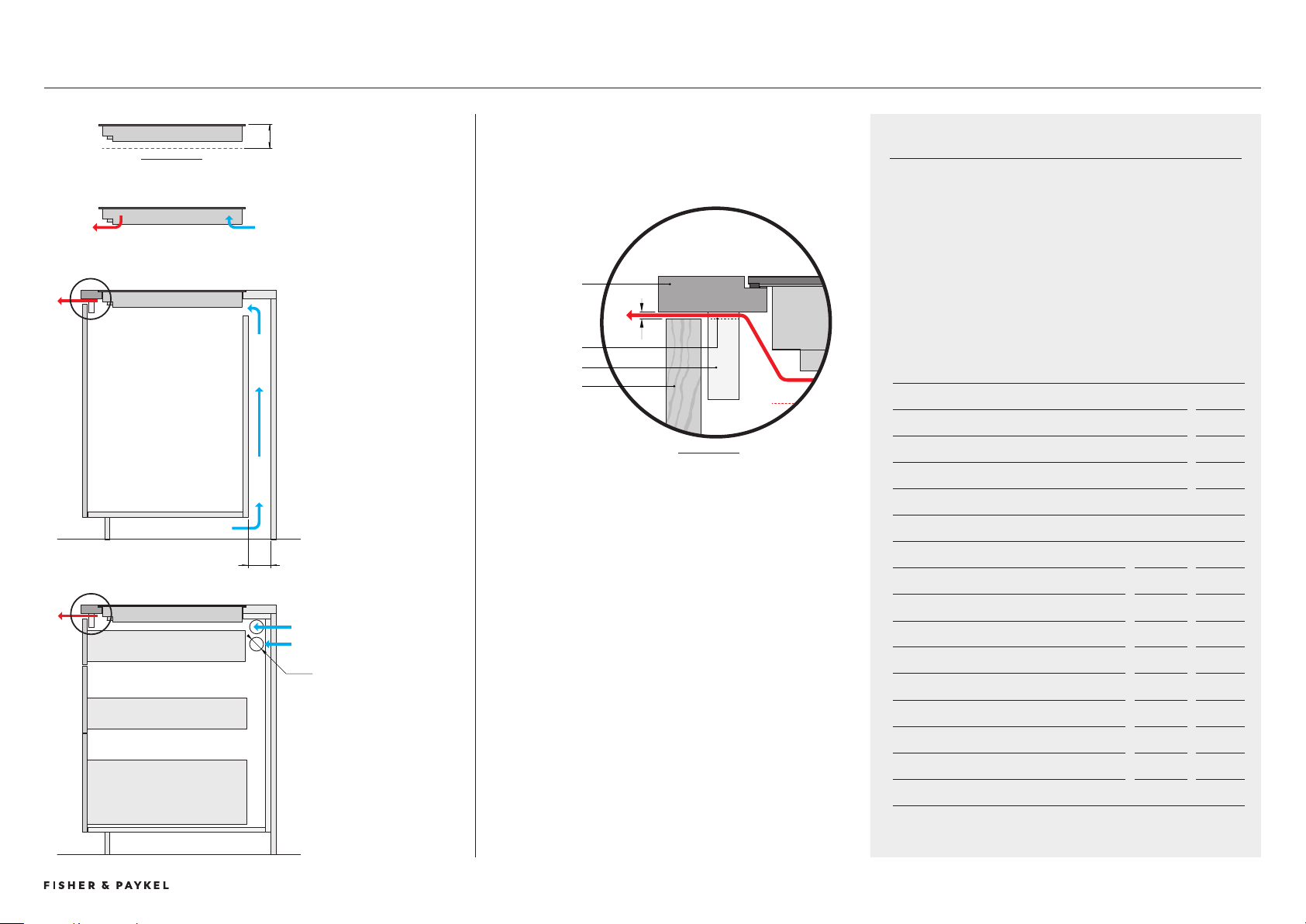
COOKTOP VENTILATION REQUIREMENTS
50mm
VENTILATION OVERVIEW
The cook modules require ventilation to allow cooling of the
electronic components within the chassis. Cooling fans are located
on the base of the product drawing cool air into the rear of the
product while hot air exits from vents at the front.
Provisions need to be made in cabinetry to allow fresh air to enter
and hot air to exit to ensure product ventilation and optimum
product performance.
When multiple products are installed their individual ventilation
requirements must also be added.
CLEARANCE REQUIREMENTS mm
a Clearance below chassis from top of cook surface
- Induction 72
- Teppanyaki 86
VENTILATION REQUIREMENTS
INTAKE at rear mm cm
B via service channel, min depth
20 -
c through adjacent cabinets, per side wall*
2x Ø50 40cm
OUTLET at front* w x h cm
D 4mm gap along width of chassis
30cm 255 x 4 10
39cm 40 x 4 14
60cm 555 x 4 22
76cm 715 x 4 0
90cm 855 x 4 4
* vents with equivlent sized area possible. Must be positioned in front of
product.
VENTILATION OUTLET
Hot air from cook modules must be able to exit at front of cabinets, th
most direct route is recommended. Small cutouts into support rail at front
of cabinet. The detail below shows one ventilation solution, other routes
are possible but must meet dimensional guidelings in table.
VENTILATION REQUIREMENTS
Air intake at rear, outlet at front
CLEARANCE REQUIREMENTS
Modules require clearance
below chassis to ensure air flow.
A
FRONT REAR
SERVICE CHANNEL INTAKE
service channel at back of
cabinetry, where fresh air is
drawn up from kick cavity.
If cavity is tightly sealed
ventilation holes in kick panel
are required.
ADJACENT CABINET INTAKE
2x Ø50 holes are required
in each side wall through to
adjacent cabinets. Total of 4x
holes required.
BENCHTOP
RAIL
FRONT PANEL
AIR VENT
b
c
D
SIDE VIEW
DETAIL 1
SIDE VIEW
1
1
Cooktop Cooling Ventilation
PLANNING CONSIDERATIONS | MODULAR COOKTOPS
© FISHER & PAYKEL LIMITED 202 PAGE 419000269A PLANNING GUIDE MODULAR COOKTOPS VERSION 1 - AUGUST 202
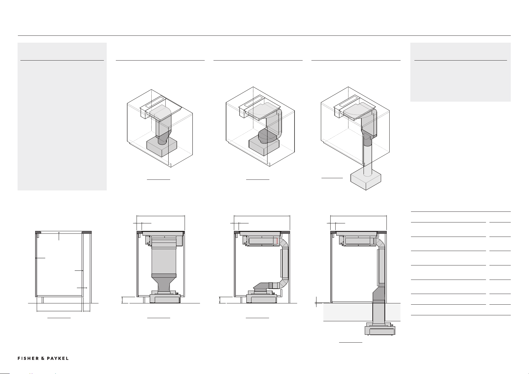
MINIMUM BENCH DEPTH ON FLOOR BLOWER SUB FLOOR BLOWER
ON FLOOR BLOWER,
STRAIGHT ADAPTER
90 DEGREE ADAPTER STRAIGHT ADAPTER
CABINETRY DIMENSIONS
mm
A Bench depth with ducting
routed within cabinet*
min 600
B Bench depth with ducting
routed through service channel*
min 700
C Nominal distance from front of
bench to front of cooktop
60
D Kick height when ducting
routed through kick cavity
min 80
E Kick height when blower
positioned in sub floor.
min 0
F Internal depth of cabinet 560
G Depth of service cavity min 80
* Cabinetry constructed from 19mm panels.
MODULAR VENTILATION CABINETRY CONSIDERATIONS
CRITICAL NOTE
It is essential to work with CAD downloads
of modular ventilation components to
design a ducting layout best suited to
specific cabinetry requirements.
b
b
C
C
f G
D
E
FRONT PANEL
CARCASS REAR
PANEL
SERVICE CHANNEL
BENCHTOP WITH
CUTOUT
FLOOR
SUB FLOOR
EG. BASEMENT
d
a
c
CABINETRY OVERVIEW
These are representational illustrations
of cabinetry and minimal ducting to
provide minimum cabinetry guidelines.
Benchtop depths are driven by ducting
requirements within cabinetry.
Other ducting layouts are possible.
Benchtop and cabinetry dimensions
should be adapted to suit requirements
specific to location, materials and
construction methods. Cabinetry may
need to be adapted with features such
as cutouts, false panels, shelf and
drawer modifications.
ISO VIEW
SIDE VIEW
SIDE VIEW
SIDE VIEW
SIDE VIEW
ISO VIEW
ISO VIEW
Cabinetry Considerations
PLANNING CONSIDERATIONS | MODULAR COOKTOPS
© FISHER & PAYKEL LIMITED 202 PAGE 429000269A PLANNING GUIDE MODULAR COOKTOPS VERSION 1 - AUGUST 202
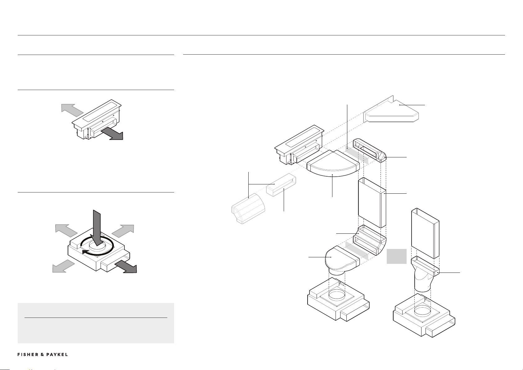
MODULAR VENTILATION COMPONENTS
Downdraft can vent to the left or right.
Blower box can be
rotated 60
MODULAR VENTILATION
KEY COMPONENTS
MODULAR VENTILATION SYSTEM
OVERVIEW WITH DUCTING COMPONENTS
Note: Indicative layout, other configurations are possible.
90 DEGREE VERTICAL ELBOW
STRAIGHT DUCTING
Cut to length
STRAIGHT ADAPTER
JOINER
ALTERNATE
ATTACHMENTS TO
DOWNDRAFT MAINBOX
ADDITIONAL
STRAIGHT
DUCTING
90 DEGREE
HORIZONTAL
ELBOW
90 DEGREE ADAPTER
OUTLET
90 DEGREE VERTICAL ELBOW
DOWNDRAFT MAINBOX
BLOWER BOX
INTAKE
IMPORTANT
Blower box inlet and outlet are offset, component is not symmetrical.
CARE TO BE TAKEN WHEN PLANNING
ADAPTER
CHOICE
METAL 90 DEGREE HORIZONTAL ELBOW
Optional accessory. Must be used over
pyrolytic oven.
Modular Ventilation
PLANNING CONSIDERATIONS | MODULAR COOKTOPS
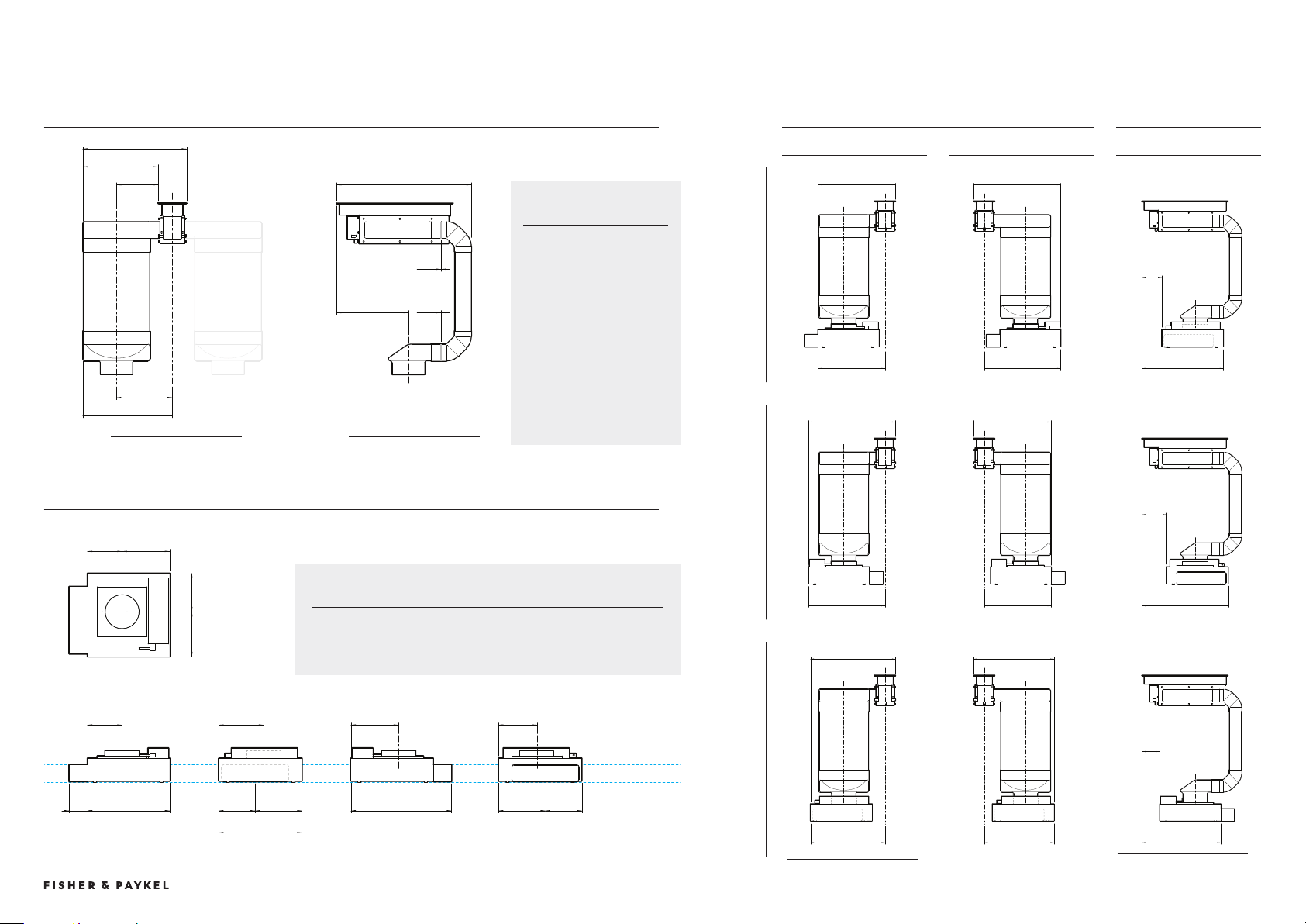
© FISHER & PAYKEL LIMITED 202 PAGE 49000269A PLANNING GUIDE MODULAR COOKTOPS VERSION 1 - AUGUST 202
MAIN BOX WITH DUCTING
TYPICAL DUCTING + DOWNDRAFT DIMENSIONS
WIDTH DIMENSIONS DEPTH DIMENSIONS
DUCT LEFT DUCT RIGHT DUCT REAR
BLOWER VENT DIRECTION
VENT REAR VENT RIGHT VENT LEFT
FRONT VIEW SIDE VIEW
Ducting dimensions
common left and
right
408
254
0min
27
617
0min
189
4
47
158
217
175
205
158
75
84
205
219
166
217
175
80
459
21
166
SIDE VIEW
FRONT VIEW
FRONT VIEW
478
41
56
471
12
502
56
471
478
41
15
52
524
459
494
429
111
485
FRONT VIEW
SIDE VIEW
REAR VIEW
SIDE VIEW
TOP VIEW
IMPORTANT NOTE
Extra attention is required during planning of blower placement in
relation to cabinetry due to asymmetry of intake and outlet.
BLOWER BOX
INTAKE AND OUTLET POSITIONS
CONSIDERATIONS
The ducting configuration
shown is a basic layout.
Dimensions stated are to
provide a starting point
for product placement and
space requirements.
Other configurations are
possible where additional
ducting can be added to
the system.
DATUM: FLOOR
DATUM: 80MM
minimum kick height
PLANNING CONSIDERATIONS | MODULAR COOKTOPS
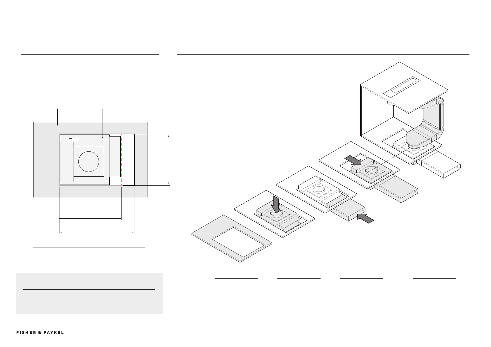
© FISHER & PAYKEL LIMITED 202 PAGE 449000269A PLANNING GUIDE MODULAR COOKTOPS VERSION 1 - AUGUST 202
BLOWER BOX CABINETRY
470 MINIMUM
570 RECOMMENDED
90 MINIMUM
ISOMETRIC VIEW
PLAN VIEW
CABINETRY FLOOR PANEL BLOWER BOX
BLOWER BOX CUTOUT
The Blower Box requires a minimum cutout of 390mm x 470mm in base
of cabinetry so it can be positioned on the floor.
For ease of installation and connection to outlet ducting it is
recommended that the cutout is increased to 390mm x 570mm.
IMPORTANT
The position of the cutout may not be central to floor panel,
pre planning is required.
BLOWER BOX INSTALLATION OVERVIEW
1
Cut hole in bottom
of cabinetry panel
2
Lower blower box
onto floor.
3
Oversized hole
allows access to
connect ducting
4
Blower repostitioned
to achieve alignment
with ducting.
PLANNING CONSIDERATIONS | MODULAR COOKTOPS
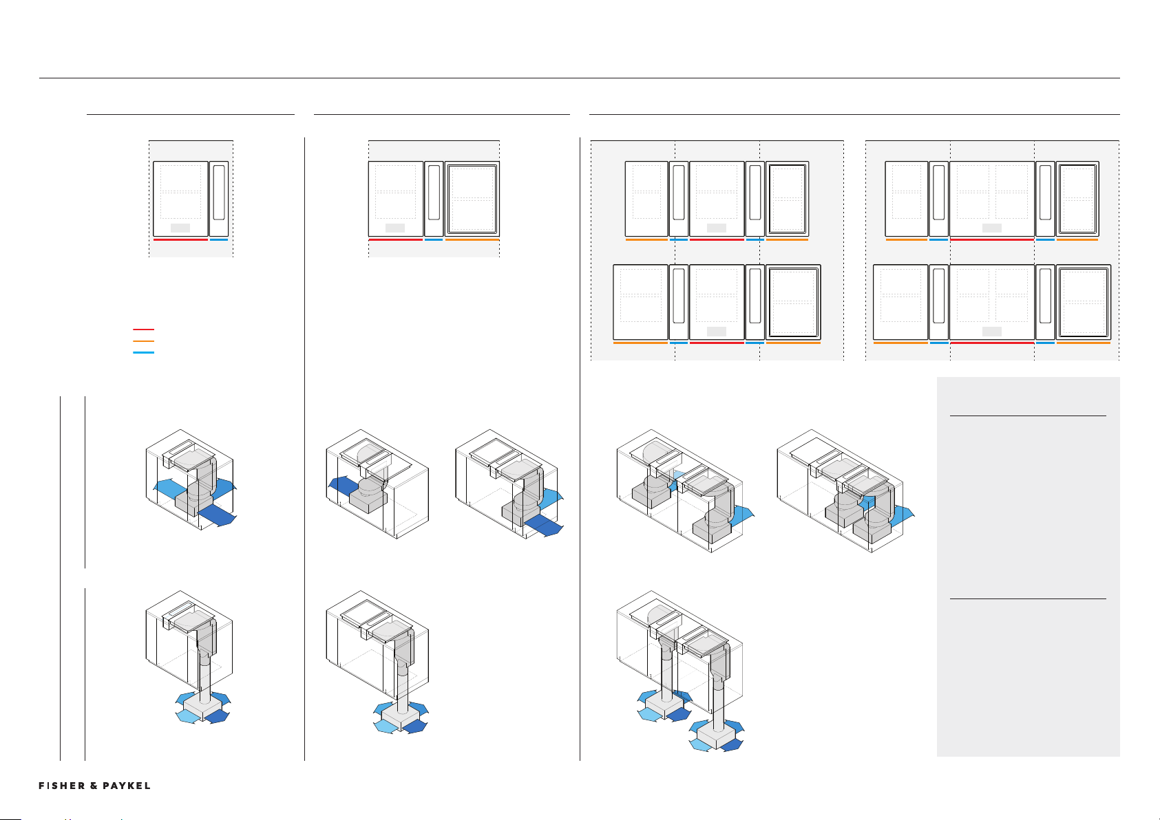
© FISHER & PAYKEL LIMITED 202 PAGE 459000269A PLANNING GUIDE MODULAR COOKTOPS VERSION 1 - AUGUST 202 © FISHER & PAYKEL LIMITED 202 PAGE 459000269A PLANNING GUIDE MODULAR COOKTOPS VERSION 1 - AUGUST 202
TYPICAL CONFIGURATIONS WITH MODULAR VENTILATION AND DUCTING
LAYOUTS APPLY TO BOTH A 9CM AND 60CM CENTRAL COOKTOP MODULE
9cm
600 600 600600 600 600
900
600
9cm9cm 0cm 9cm 0cm
9cm 9cm 9cm
0cm 60cm 0cm
9cm 60cm 9cm
SINGLE - COMPACT <600 TWO IN A ROW - MID <900 THREE IN A ROW - WIDE >1200
SPACE REQUIREMENTS
These are representational
illustrations of typical
configurations with modular
ventilation and ducting installed
in standardised cabinetry widths
to provide an overview of
cabinetry requirements. Other
configurations are possible.
IMPORTANT
A full assessment should be
undertaken of chosen modular
components within cabinetry
dimensions specific to location,
materials and construction
methods.
BLOWER PLACEMENT
SUB-FLOOR BLOWER BOX ON FLOOR BLOWER BOX
Ducting can also exit to left.
Ducting can also exit to left.
Ducting can also exit to left.
Configurations can not be mirrored. Layout determined due to
asssymetry of blower box.
Layout can be mirrored.
PRIMARY COOKTOP
AUXILIARY COOKTOP
AUXILIARY VENTILATION
Typical Cabinetry Configurations
PLANNING CONSIDERATIONS | MODULAR COOKTOPS
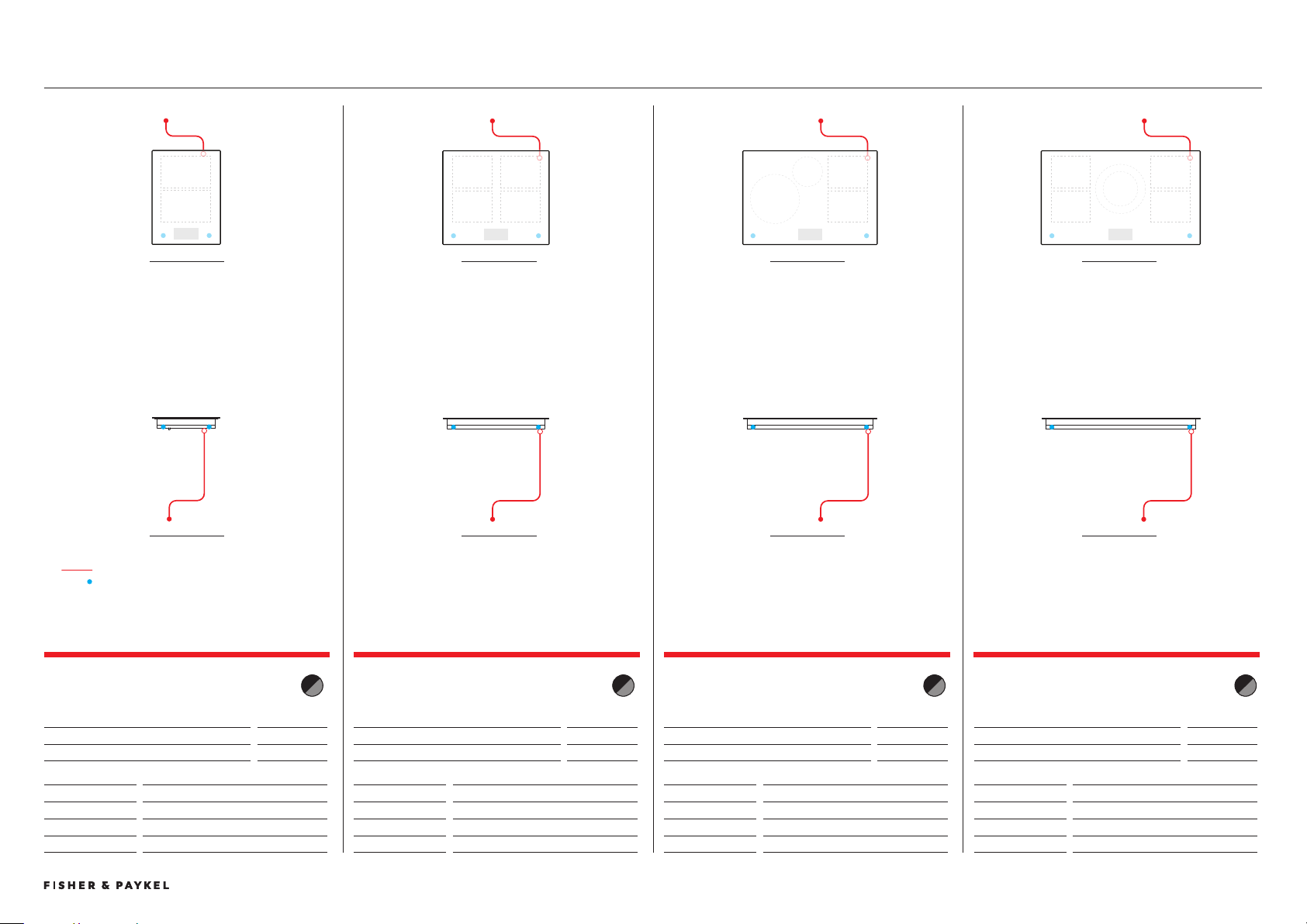
© FISHER & PAYKEL LIMITED 202 PAGE 469000269A PLANNING GUIDE MODULAR COOKTOPS VERSION 1 - AUGUST 202 © FISHER & PAYKEL LIMITED 202 PAGE 469000269A PLANNING GUIDE MODULAR COOKTOPS VERSION 1 - AUGUST 202
SERVICES
PRIMARY MODULAR INDUCTION COOKTOP, 39CM,
2 ZONES WITH SMARTZONE
Model no:
CI92DTTB1 Black
CI92DTTG1 Grey
Dimensions
mm
Power Cable
1700
Power Requirements
Supply
220-240V, 50Hz/60Hz
Maximum Power
.7kW
Connection
Power cable, stripped wires, 1N
PRIMARY MODULAR INDUCTION COOKTOP, 60CM,
4 ZONES WITH SMARTZONE
Model no:
CI92DTTB1 Black
CI92DTTG1 Grey
Dimensions
mm
Power Cable not supplied
Power Requirements
Supply
220-240V, 50Hz/60Hz
Maximum Power
7.4kW
Connection
Terminal block, 1N or 2N
PRIMARY MODULAR INDUCTION COOKTOP, 76CM,
4 ZONES WITH SMARTZONE
Model no:
CI92DTTB1 Black
CI92DTTG1 Grey
Dimensions
mm
Power Cable
not supplied
Power Requirements
Supply
220-240V, 50Hz/60Hz
Maximum Power
7.4kW
Connection
Terminal block, 1N or 2N
PRIMARY MODULAR INDUCTION COOKTOP, 90CM,
5 ZONES WITH SMARTZONE
Model no:
CI92DTTB1 Black
CI92DTTG1 Grey
Dimensions
mm
Power Cable
not supplied
Power Requirements
Supply
220-240V, 50Hz/60Hz
Maximum Power
11.1kW
Connection
Terminal block, 1N or N
FRONT VIEW
TOP VIEW
FRONT VIEW
TOP VIEW
FRONT VIEW
TOP VIEW
FRONT VIEW
TOP VIEW
POWER CABLE
COMMUNICATION PORT
Electrical Services
PLANNING CONSIDERATIONS | MODULAR COOKTOPS
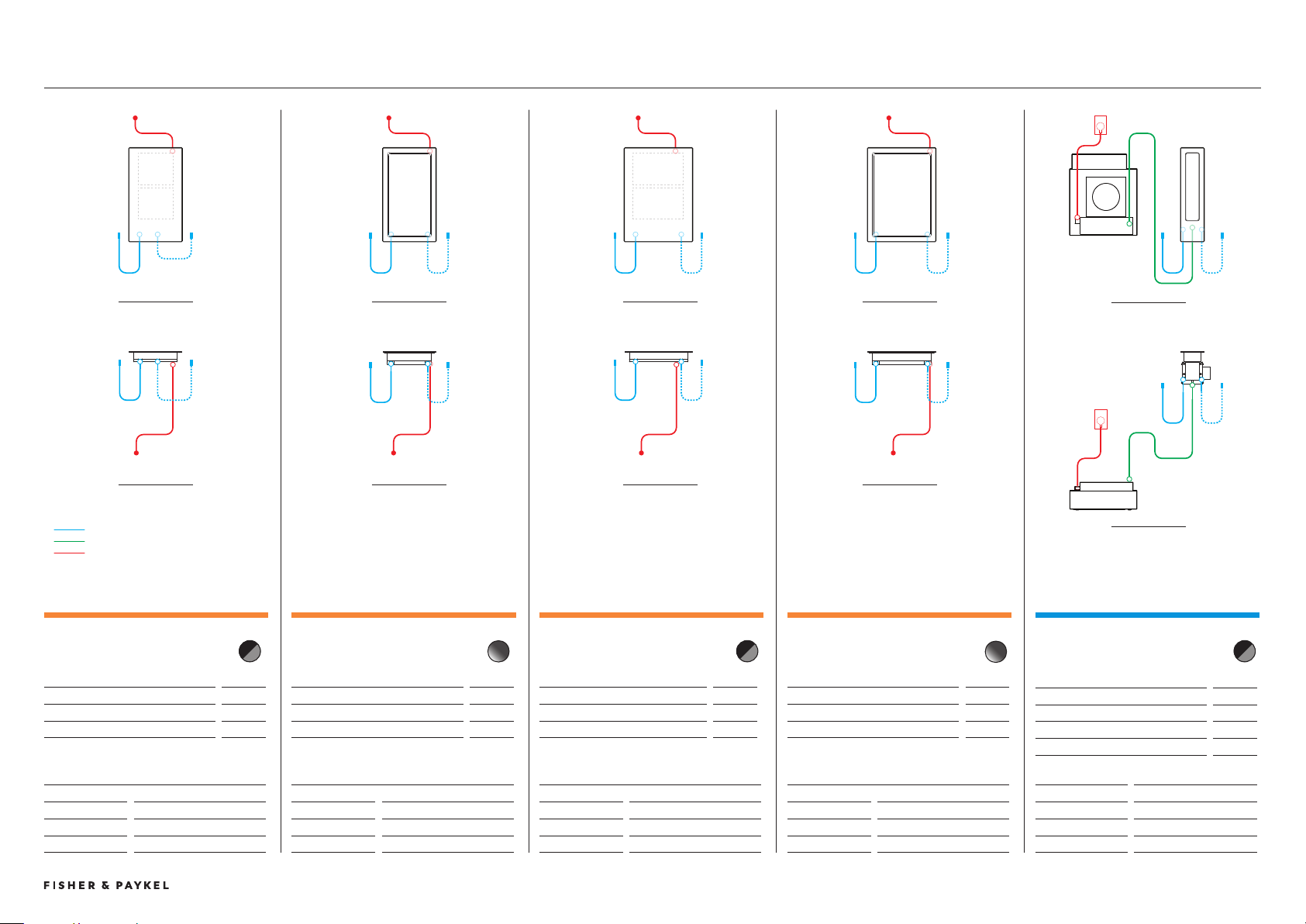
© FISHER & PAYKEL LIMITED 202 PAGE 479000269A PLANNING GUIDE MODULAR COOKTOPS VERSION 1 - AUGUST 202
SERVICES
AUXILIARY MODULAR TEPPANYAKI COOKTOP,
30CM, 2 ZONES
Model no:
CIT02DX1
Dimensions
mm
External Communication Harness*
500
Power Cable*
1700
* x1 supplied with each auxiliary unit
Power Requirements
Supply
220-240V, 50Hz/60Hz
Maximum Power
2.8kW
Connection
Power cable, stripped wires, 1N
AUXILIARY MODULAR INDUCTION COOKTOP,
30CM, 2 ZONES WITH SMARTZONE
Model no:
CI02DB1 Black
CI02DG1 Grey
Dimensions
mm
External Communication Harness*
500
Power Cable*
1700
* x1 supplied with each auxiliary unit
Power Requirements
Supply
220-240V, 50Hz/60Hz
Maximum Power
.7kW
Connection
Power cable, stripped wires, 1N
AUXILIARY MODULAR TEPPANYAKI COOKTOP,
39CM, 2 ZONES
Model no:
CI92DX1
Dimensions
mm
External Communication Harness*
500
Power Cable*
1700
* x1 supplied with each auxiliary unit
Power Requirements
Supply
220-240V, 50Hz/60Hz
Maximum Power
2.8kW
Connection
Power cable, stripped wires, 1N
AUXILIARY MODULAR INDUCTION COOKTOP,
39CM, 2 ZONES WITH SMARTZONE
Model no:
CI92DB1 Black
CI92DG1 Grey
Dimensions
mm
External Communication Harness*
500
Power Cable*
1700
* x1 supplied with each auxiliary unit
Power Requirements
Supply
220-240V, 50Hz/60Hz
Maximum Power
.7kW
Connection
Power cable, stripped wires, 1N
AUXILIARY MODULAR VENTILATION, 13CM
Model no:
CD1DB1 Black
CD1DG1 Grey
Dimensions
mm
External Communication Harness*
500
Central Communication Harness*
1700
Power Cable
000
* x1 supplied with each auxiliary unit
Power Requirements
Supply
220-240V, 50Hz
Maximum Power
167W
Connection
Power cable, plug
FRONT VIEW
TOP VIEW
FRONT VIEW
TOP VIEW
FRONT VIEW
TOP VIEW
FRONT VIEW
TOP VIEW
FRONT VIEW
TOP VIEW
EXTERNAL COMMUNICATION HARNESS
CENTRAL COMMUNICATION HARNESS
POWER CABLE
PLANNING CONSIDERATIONS | MODULAR COOKTOPS
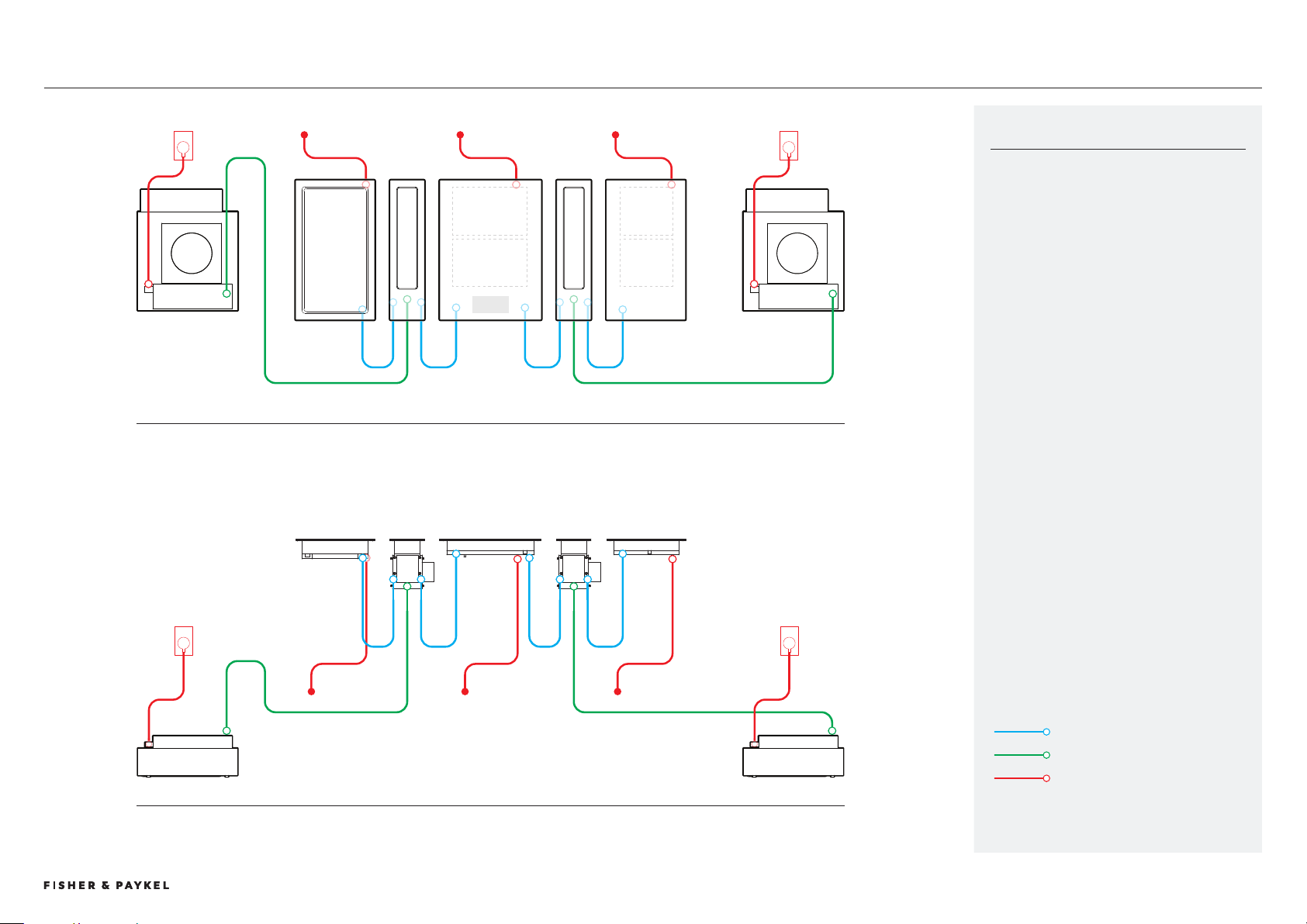
© FISHER & PAYKEL LIMITED 202 PAGE 489000269A PLANNING GUIDE MODULAR COOKTOPS VERSION 1 - AUGUST 202 © FISHER & PAYKEL LIMITED 202 PAGE 489000269A PLANNING GUIDE MODULAR COOKTOPS VERSION 1 - AUGUST 202
MODULAR CONNECTIONS
FRONT VIEW
TOP VIEW
EXTERNAL COMMUNICATION HARNESS
CENTRAL COMMUNICATION HARNESS
POWER CABLE
SUPPLIED HARNESS
External communication harnesses connect
auxiliary modules to the primary module. These
connections must be do the product directly
adjacent in a 'daisy chain' configuration (refer
diagram).
1x External communication harness is supplied
with each auxiliary module (induction,
teppanyaki and downdraft ventilation).
1x Central communication harness is supplied
with auxiliary modular ventilation to connect
downdraft unit with blower box.
PLANNING CONSIDERATIONS | MODULAR COOKTOPS