
Loading ...
Loading ...
Loading ...
© FISHER & PAYKEL LIMITED 202 PAGE 59000269A PLANNING GUIDE MODULAR COOKTOPS VERSION 1 - AUGUST 202
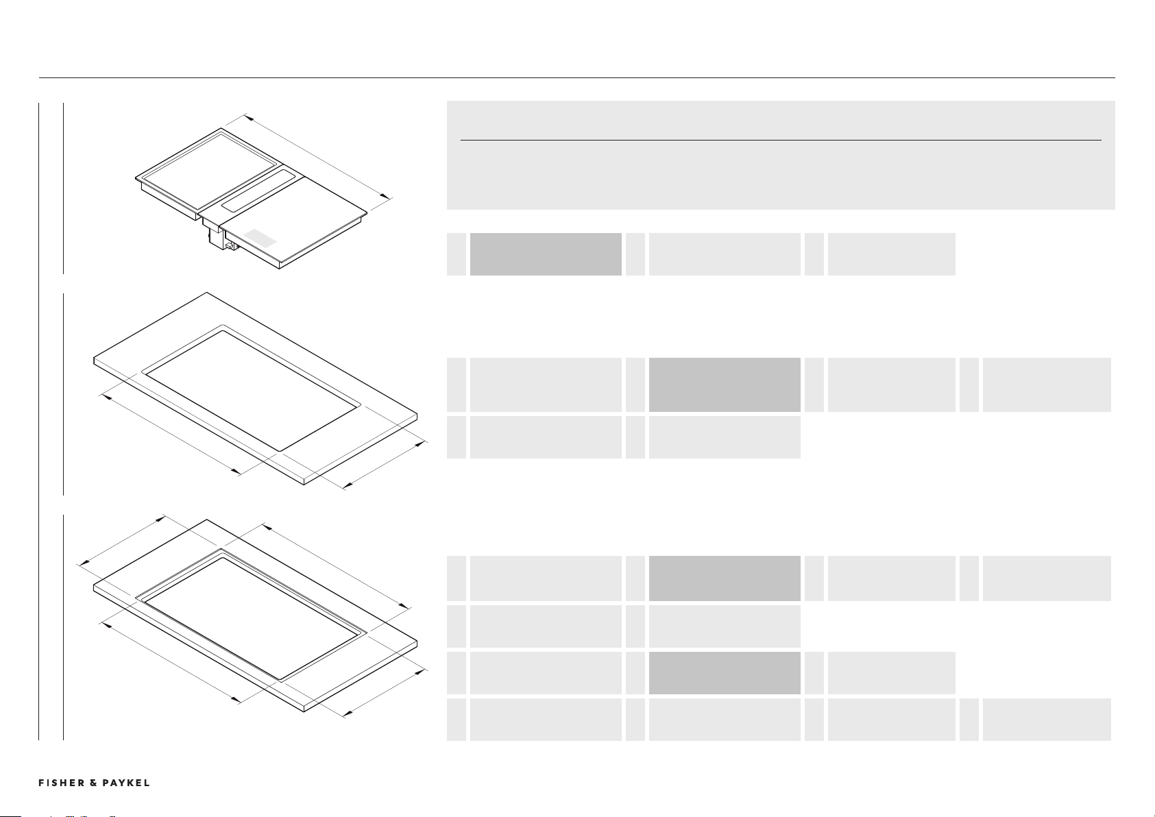
COMBINED INSTALLATION OVERVIEW
A
e
d
c
b
F
b
A
OVERALL WIDTH OF MODULES = COMBINED PRODUCT WIDTHS
add module widths
+ GAPS BETWEEN MODULES
2mm x (number of modules -1)
b
WIDTH OF CUTOUT
FLUSH AND PROUD
= OVERALL WIDTH OF MODULES - LEFT OVERHANG
19mm Induction / Teppanyaki OR
17mm Downdraft
- RIGHT OVERHANG
19mm Induction / Teppanyaki OR
17mm Downdraft
c
DEPTH OF CUTOUT
PROUD
= 507MM
b
WIDTH OF CUTOUT
FLUSH AND PROUD
= OVERALL WIDTH OF MODULES - LEFT OVERHANG
19mm Induction / Teppanyaki OR
17mm Downdraft
- RIGHT OVERHANG
19mm Induction / Teppanyaki OR
17mm Downdraft
d
DEPTH OF CUTOUT
FLUSH
= 509mm
e
WIDTH OF RECESS
FLUSH
= OVERALL WIDTH OF MODULES + 4mm
2mm each side
f
DEPTH OF RECESS
FLUSH
= 54mm = 50mm
product depth
+ 4mm
2mm top and bottom
COMBINED BENCHTOP EQUATIONS
Pairings of modular products have been designed to fit in a singular benchtop cutout. When grouping modules it is essential to calculate their
combined cutout requirements. The following equations can be used to guide calculations.
For dimensions of common configurations please refer to subsequent pages.
FLUSH PROUD MODULES
Combined Installation
PLANNING CONSIDERATIONS | MODULAR COOKTOPS
Loading ...
Loading ...
Loading ...