USSC 1
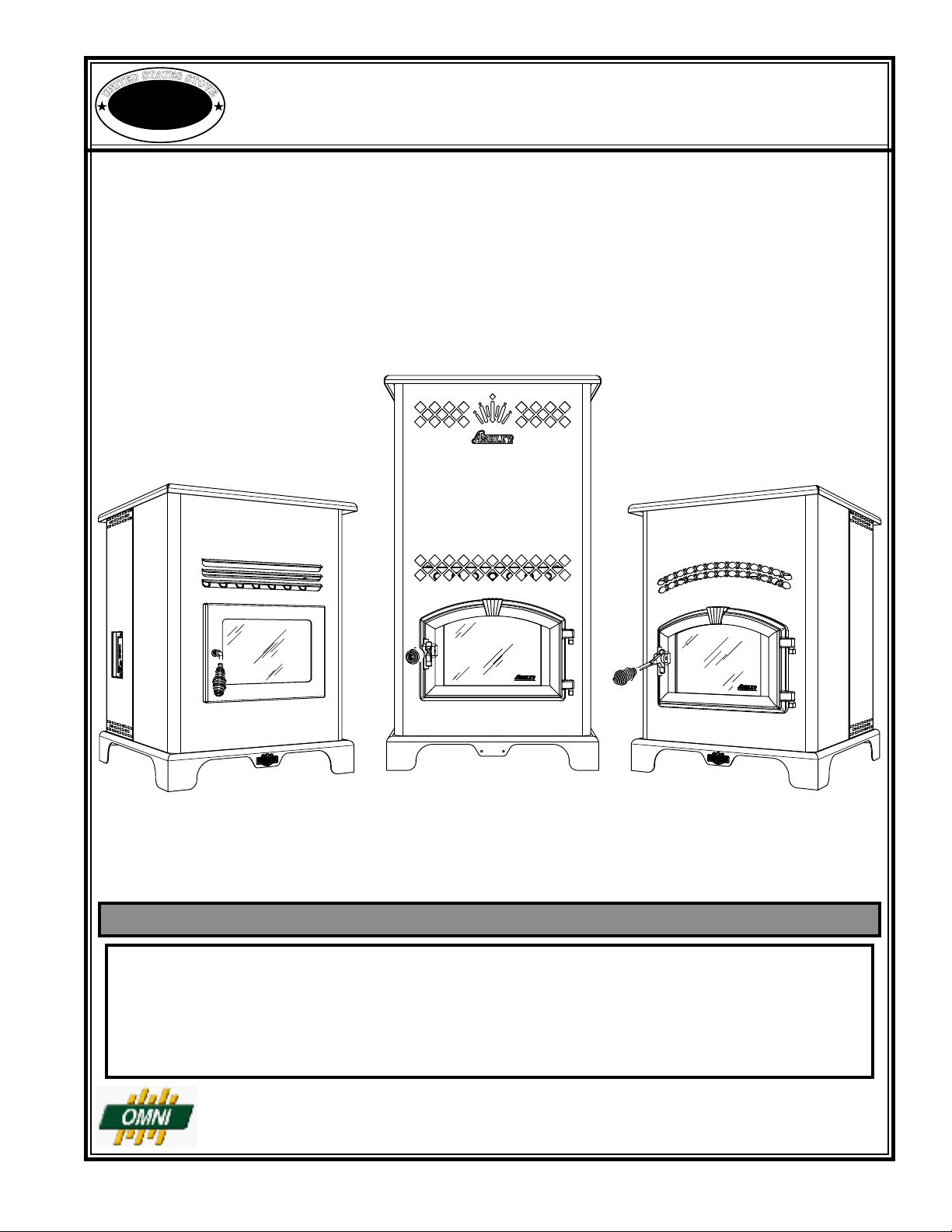
King/Ashley Pellet Stove
Please read this entire manual before installation and use of this appliance. Failure to follow
these instructions could result in property damage, bodily injury, or even death.
Contact your local building or re ofcials about restrictions and installation inspection
requirements in your area.
Save these instructions.
Owner’s Manual
UNITED STATES STOVE COMPANY • 227 INDUSTRIAL PARK ROAD • SOUTH PITTSBURG, TENNESSEE 37380 • WWW.USSTOVE.COM
FOR TECHNICAL ASSISTANCE: PHONE: (800) 750-2723 FAX: (423) 837-2109
Part No.: 851641
UNITED STATES STOVE COMPANY
“Keeping North America Warm Since 1869”
models 5500/5500M/5500XL
C
S
S
U
C
O
M
P
A
N
Y
U
N
I
T
E
D
S
T
A
T
E
S
S
T
O
V
E
5500M
5500XL
5500
E

2 USSC
TABLE OF CONTENTS .............................................................................................. 2
SAFETY PRECAUTIONS ........................................................................................... 3
SPECIFICATIONS ....................................................................................................... 4
HeatingSpecications .....................................................................................4
Dimensions ......................................................................................................4
ElectricalSpecications ...................................................................................4
FuelConsiderations .........................................................................................4
SafetyandEPACompliance ............................................................................ 4
INSTALLATION .......................................................................................................... 5
InstallationOptions ..........................................................................................5
FloorProtection ............................................................................................... 5
Clearances ......................................................................................................6
VentingRequirements ..................................................................................... 7
MaximumVentingDistance ............................................................................. 7
PelletVentType ...............................................................................................7
PelletVentInstallation ..................................................................................... 7
PelletVentTermination ....................................................................................7
VentTerminationClearances ...........................................................................8
ThroughtheWallInstallation ........................................................................... 9
ThroughtheRoof/CeilingInstallation............................................................... 9
OutsideAirSupply ......................................................................................... 10
SpecialMobileHomeRequirements ............................................................. 10
UNDERSTANDING YOUR STOVE ........................................................................... 11
CONTROL PANEL OVERVIEW ................................................................................ 12
OPERATION ........................................................................................................13-15
UnitPreparation .............................................................................................13
PerformingInitialTest ....................................................................................13
Performinga“DryRun” ..................................................................................13
Start-UpProcedure ........................................................................................14
ShutDownProcedure ....................................................................................14
DailyOperation ..............................................................................................15
SafetyandConvenienceFeatures ................................................................ 15
MAINTENANCE ...................................................................................................15-16
ExhaustSystem .............................................................................................15
InteriorChambers ..........................................................................................16
AshDisposal ..................................................................................................16
CheckandCleantheHopper ........................................................................ 16
MainDoorGaskets ........................................................................................16
BlowerMotors ................................................................................................16
PaintedSurfaces ........................................................................................... 16
Glass ..............................................................................................................16
Fall Start-Up ...................................................................................................16
SpringShutDown ..........................................................................................16
YearlyServicing .............................................................................................16
TROUBLE SHOOTING ............................................................................................. 17
ERROR CODES & DISPLAY INDICATORS ............................................................. 18
REPAIR PARTS DIAGRAM/LIST ........................................................................19-21
WIRING DIAGRAM ................................................................................................... 22
Table of Contents

USSC 3
Safety Precautions
IMPORTANT:Readthisentiremanualbeforeinstalling
and operating this product. Failure to do so may
resultinpropertydamage,bodilyinjury,orevendeath.
Properinstallationofthisstoveiscrucialforsafeand
efcientoperation.
Install vent at clearances specified by the vent
manufacturer.
Donotconnectthepelletventtoaventservingany
otherapplianceorstove.
Do not install a ue damper in the exhaust venting
systemofthisunit.
Useofoutsideairisnotrequiredforthisunit.
Contact your local building officials to obtain a
permitandinformationonanyadditionalinstallation
restrictionsorinspectionrequirementsinyourarea.
Do not throw this manual away. This manual has
important operating and maintenance instructions
thatyouwillneedatalatertime.Alwaysfollowthe
instructionsinthismanual.
ThisDSSOLDQFHLVGHVLJQHGIRUWKHXVHRISHOOHWL]HGIXHO
WKDWmeet or exceed the standard set by the Pellet)XHO
Institute(PFI). The use of other fuels will voidZDUUDQW\
Never use gasoline, gasoline-type lantern fuel,
kerosene, charcoal lighter uid, or similar liquids to
startor’freshenup’areinthisstove.Keepallsuch
liquidswellawayfromthestovewhileitisinuse.
Aworkingsmokedetectormustbeinstalledinthesame
roomasthisproduct.
Donotunplugthestoveifyoususpectamalfunction.
TurntheON/OFFSWITCHto”OFF’andcontactyour
dealer.
Yourstoverequiresperiodicmaintenanceandcleaning
(see”MAINTENANCE”).Failuretomaintainyourstove
mayleadtoimproperand/orunsafeoperation.
Disconnect the power cord before performing any
maintenance!NOTE:TurningtheON/OFFSwitchto
”OFF”doesnotdisconnectallpowertotheelectrical
componentsofthestove.
Nevertrytorepairorreplaceanypartofthestoveun-
lessinstructionsfordoingsoaregiveninthismanual.
Allotherworkshouldbedonebyatrainedtechnician.
Do not operate your stove with the viewing door
open. The auger will not feed pellets under these
circumstancesandasafetyconcernmayarisefrom
sparksorfumesenteringtheroom.
A
llow
the stove to cool before performing any
maintenance or cleaning. Ashes must be disposed
inametalcontainerwithatightttinglid.Theclosed
container of ashes should be placed on a non-
combustiblesurfaceorontheground,wellawayfrom
allcombustiblematerials,pendingnaldisposal.
Theexhaustsystemshouldbecheckedmonthlyduring
theburningseasonforanybuild-upofsootorcreosote.
Donottouchthehotsurfacesofthestove.Educateall
childrenonthedangersofahigh-temperaturestove.
Youngchildrenshouldbesupervisedwhentheyare
inthesameroomasthestove.
Thehopperandstovetopwillbehotduringoperation;
therefore,youshouldalwaysusesometypeofhand
protectionwhenrefuelingyourstove.
Apowersurgeprotectorisrequired.Thisunitmust
be plugged into a 110 - 120V, 60 Hz grounded
electricaloutlet.Donotuseanadapterplugorsever
the grounding plug. Do not route the electrical cord
underneath, in front of, or over the heater. Do not
routethecordinfoottrafcareasorpinchthecord
underfurniture.
Theheaterwillnotoperateduringapoweroutage.Ifa
poweroutagedoesoccur,checktheheaterforsmoke
spillageandopenawindowifanysmokespillsinto
theroom.
The feed door must be closed and sealed during
operation.
Never block free airow through the open vents of
theunit.
Keepforeignobjectsoutofthehopper.
Themovingpartsofthisstovearepropelledbyhigh
torqueelectricmotors.Keepallbodypartsawayfrom
theaugerwhilethestoveispluggedintoanelectrical
outlet.Thesemovingpartsmaybegintomoveatany
timewhilethestoveispluggedin.
Donotplaceclothingorotherammableitemsonor
nearthisstove.
When installed in a mobile home, the stove must
begroundeddirectlytothesteelchassisandbolted
to the oor. WARNING—THIS UNIT MUST NOT
BE INSTALLED IN THE BEDROOM (per HUD
requirements). CAUTION—THE STRUCTURAL
INTEGRITYOFTHEMOBILEHOMEFLOOR,WALL,
ANDCEILING/ROOFMUSTBEMAINTAINED.
Thisapplianceisnotintendedforcommercialuse.
*Thisapplianceisafreestandingheater.Itisnotintendedtobeattachedtoanytypeofducting.Itisnotafurnace.

4 USSC
Specications
HeatOutput
1
48,000BTU/hr.
Heating Capacity
2
800-2,000sq.ft.
Fuel Burn Rate
3
2.0-6.0lbs./hr.
BurnTime(lowestsetting) 5500/5500M-60hrs. 5500XL -160hrs.
HopperCapacity 5500/5500M-150lbs. 5500XL-320lbs.
5500/5500M 5500XL
Height
34in. 471/4in.
Width
26 in. 26 in.
Depth
25 in. 25 in.
Weight 250lbs. 275lbs.
1
BTUoutputwillvarydependingonthequalityoffuel.UsePFIlistedfuelsforthebestresults.
2
Heatingcapacitywillvarydependingonoorplanlayoutofyourhome,degreeofinsulation,andtheoutsidetemperature.
3
Pelletsizemayeffecttheactualrateoffuelfeedandburntimes.Fuelfeedratesmayvarybyasmuchas20%.UsePFIlistedfuelforbestresults.
Electrical Rating
110-120volts,60HZ,3.0Amps
Watts(operational)
175(approx.)
Watts(igniterrunning)
425(approx.)
FUEL CONSIDERATIONS
Your King/Ashley stove is designed to burn premium hardwoodpellets that comply withAssociationof Pellet Fuel
Industriesstandards.(Minimumof40lbsdensitypercubicft,1/4”to5/16”diameter,lengthnogreaterthan1.5”,notless
than8,200BTU/lb,moistureunder8%byweight,ashunder1%byweight,andsaltunder300partspermillion).Pellets
thataresoft,containexcessiveamountsofloosesawdust,havebeen,orarewet,willresultinreducedperformance.
SAFETY AND EPA COMPLIANCE
YourKing/Ashley stove hasbeensafetytestedandlistedtoASTME1509,(UM)84-HUDbyOMNI-TestLaboratories,
Inc.Portland,Oregon,USA.ItisalsocertiedandtestedtoEPAPhaseIIrequirements.
USSC 5
INSTALLATION OPTIONS
King/Ashley
A—supportedbypedestal/legsandplacedonanon-combustibleoorsurfaceincompliancewith
clearancerequirementsforafreestandingstoveinstallation.
An—supportedbypedestal/legsandplacedonanon-combustibleoorsurfaceincompliancewithclearance
requirementsforanalcoveinstallation.
YourKing/Ashley stovemaybeinstalledtocodeineitheraor(seeSPECIALMOBILE
HOMEREQUIREMENTS).
ItisrecommendedthatonlyaauthorizedtechnicianinstallyourKing/Ashley stove,preferablyanNFIcertiedspecialist.
Installation
IMPROPER INSTALLATION: Themanufacturerwillnotbeheldresponsiblefordamagecausedbythemalfunc-
tionofastoveduetoimproperventingorinstallation.Call(800)750-2723and/orconsultaprofessionalinstaller
ifyouhaveanyquestions.
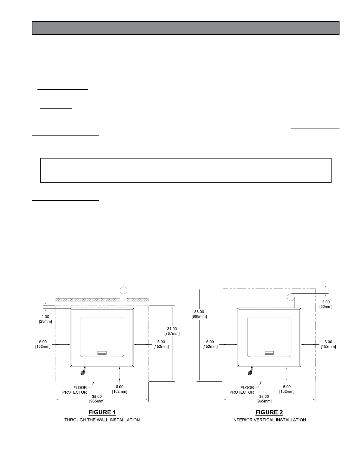
FLOOR PROTECTION
Thisunitmustbeinstalledonanon-combustibleoorsurface.Ifaoorpadisused,itshouldbeULlistedorequal.
Theoorpadornon-combustiblesurfaceshouldbelargeenoughtoextendaminimumof6-inchesinfront,6-incheson
eachside,and1-inchbehindthestove(seeFIGURE1).
Floorprotectionmustextendunderand2-inchestoeachsideofthechimneyteeforaninteriorverticalinstallation(see
FIGURE2).
YourKing/Ashley stovewillneedaminimum31”x38”oorprotector.
AFloorProtectorof1inchthickisrecommendedforthisinstallation.
6 USSC
Installation
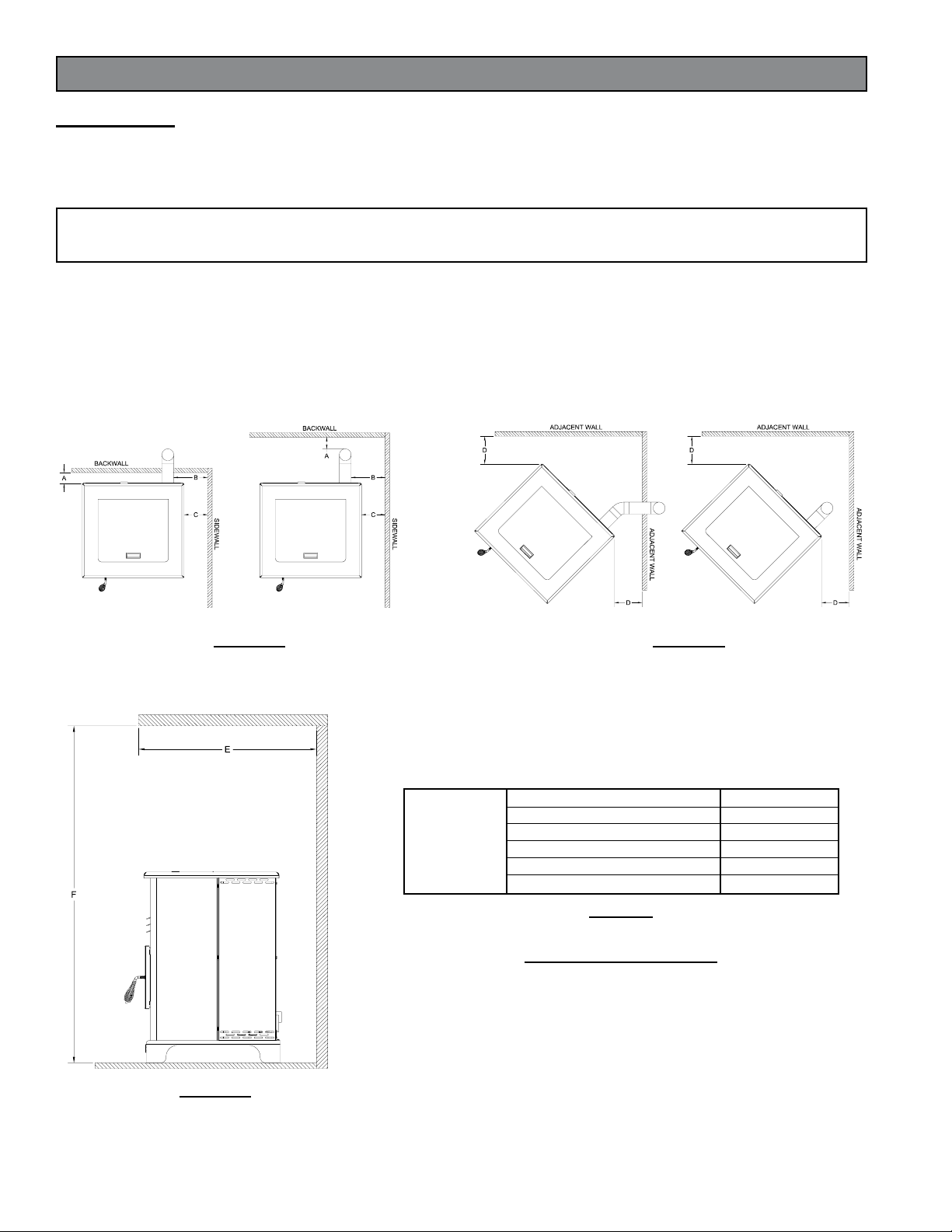
CLEARANCES
YourKing/Ashleystovehasbeentestedandlistedforinstallationinresidential,mobilehome,andalcoveapplications
inaccordancewiththeclearancesgiveninFIGURES3-5andTABLE1.
NOTE: Distance “C” on the left-hand side of your King/Ashley stove may need to be greater than the mini-
mum required clearance for suitable access to the control panel.
FIGURE 3
SIDEWALLCLEARANCES
PARALLELINSTALATION
FIGURE 4
SIDEWALLCLEARANCES
CORNERINSTALATION
FIGURE 5
ALCOVECLEARANCES
PARALLEL A-Backwalltounit 2.00/50mm
B-Sidewalltoue 13.00/330mm
C-Sidewalltotopedgeofunit 8.00/203mm
CORNER D-Adjacentwalltounit 8.00/203mm
ALCOVE E-Alcovedepth 36.00-914mm
(5500(M)only) F-Alcoveheight 60.00-1520mm
TABLE 1
CLEARANCES
ALCOVE INSTALLATION
THIS INSTALLATION IS NOT APPLICABLE
FOR MODEL 5500XL.
USSC 7
Installation
VENTING REQUIREMENTS
Thefollowinginstallationguidelinesmustbefollowedtoensureconformitywithboththesafetylistingofthisstoveand
tolocalbuildingcodes.
Thisunitisequippedwithanegativedraftsystemthatpullsairthroughtheburnpotand
pushestheexhaustoutofthedwelling.Ifthisunitisconnectedtoauesystemotherthanthewayexplained
inthismanual,itwillnotfunctionproperly.
MAXIMUM VENTING DISTANCE
InstallationMUSTincludeatleast3-feetofverticalpipeoutsidethehome.Thiswillcreatesomenaturaldrafttoreducethe
possibilityofsmokeorodorduringapplianceshutdownandkeepexhaustfromcausinganuisanceorhazardbyexposing
peopleorshrubstohightemperatures.Themaximumrecommendverticalventingheightis12-feetfor3-inchtype“PL”
vent.TotallengthofhorizontalventMUSTNOTexceed4-feet.Thiscouldcausebackpressure.Usenomorethan180
degreesofelbows(two90-degreeelbows,ortwo45-degreeandone90-degreeelbow,etc.)tomaintainadequatedraft.
PELLET VENT TYPE
AULlisted3-inchor4-inchtype“PL”pelletventexhaustsystemmustbeusedforinstallationandattachedtothepipe
connectorprovidedonthebackofthestove(usea3-inchto4-inchadapterfor4-inchpipe).Connectionatbackof
stovemustbesealedusingHi-TempRTV.Use4-inchventiftheventheightisover12-feetoriftheinstallationisover
2,500feetabovesealevel.
WerecommendtheuseofSimpsonDura-Vent
®
orMetal-Fab
®
pipe(ifyouuseotherpipe,consultyourlocalbuilding
codesand/orbuildinginspectors).DonotuseType-BGasVentpipeorgalvanizedpipewiththisunit.Thepelletvent
pipeisdesignedtodisassembleforcleaningandshouldbecheckedseveraltimesduringtheburningseason.Pellet
ventpipeisnotfurnishedwiththeunitandmustbepurchasedseparately.
PELLET VENT INSTALLATION
Theinstallationmustincludeaclean-outteetoenablecollectionofyashandtopermitperiodiccleaningoftheexhaust
system.90-degreeelbowsaccumulateyashandsoottherebyreducingexhaustowandperformanceofthestove.
Eachelboworteereducesdraftpotentialby30%to50%.
Alljointsintheventsystemmustbefastenedbyatleast3screws,andalljointsmustbesealedwithHi-TempRTV
siliconesealanttobeairtight.Theareawheretheventpipepenetratestotheexteriorofthehomemustbesealedwith
siliconeorothermeanstomaintainthevaporbarrierbetweentheexteriorandtheinteriorofthehome.
Ventsurfacescangethotenoughtocauseburnsiftouchedbychildren.Noncombustibleshieldingorguardsmaybe
required.
PELLET VENT TERMINATION
Donotterminatetheventinanenclosedorsemi-enclosedarea,suchas;carport,garage,attic,crawlspace,undera
sundeckorporch,narrowwalkway,oranyotherlocationthatcanbuildupaconcentrationoffumes.
Theterminationmustexhaustabovetheoutsideairinletelevation.
Theterminationmustnotbelocatedwhereitwillbecomepluggedbysnoworothermaterials.
Donotterminatetheventingintoanexistingchimney.
8 USSC
Installation
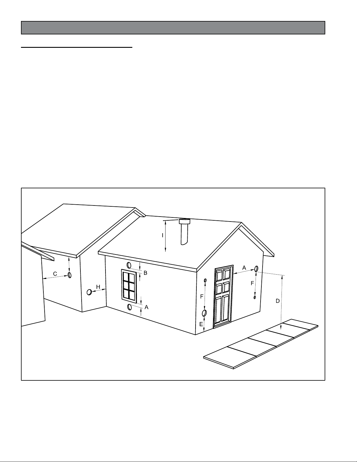
VENT TERMINATION CLEARANCES:
A) Minimum4-footclearancebeloworbesideanydoororwindowthatopens.
B) Minimum1-footclearanceaboveanydoororwindowthatopens.
C) Minimum3-footclearancefromanyadjacentbuilding.
D) Minimum7-footclearancefromanygradewhenadjacenttopublicwalkways.
E) Minimum2-footclearanceaboveanygrass,plants,orothercombustiblematerials.
F) Minimum3-footclearancefromanforcedairintakeofanyappliance.
G)Minimum2-footclearancebelowevesoroverhang.
H) Minimum1-footclearancehorizontallyfromcombustiblewall.
I) Mustbeaminimumof36-inchesabovetheroofand24-inchesabovethehighestpointortheroofwithin10-feet.
G
USSC 9
Installation
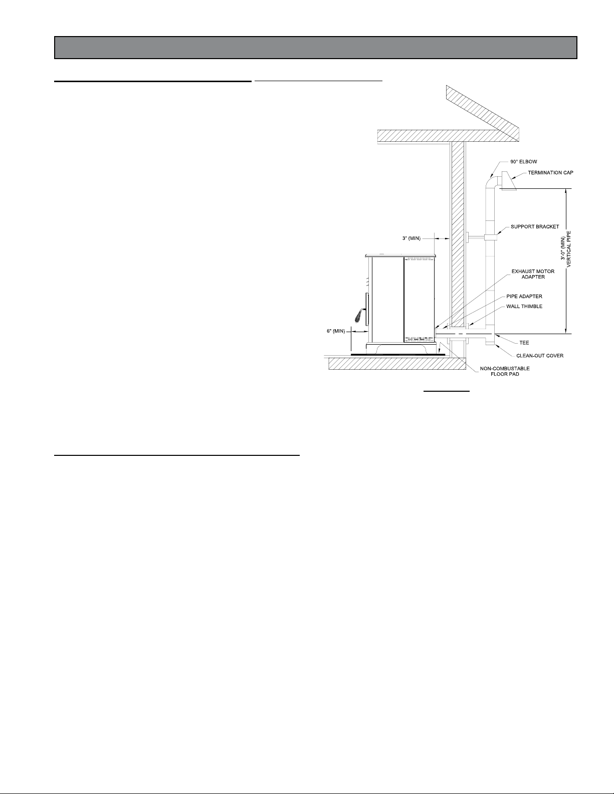
THROUGH THE WALL INSTALLATION (RECOMMENDEDINSTALLATION)
Toventtheunitthroughthewall,connectthepipeadapter
totheexhaustmotoradapter.Iftheexhaustadapterisat
least18-inchesabovegroundlevel,astraightsectionof
pelletventpipecanbeusedthroughthewall.
YourKing/Ashleydealershouldbeabletoprovideyou
withakitthatwillhandlemostofthisinstallation,whichwill
includeawallthimblethatwillallowtheproperclearance
throughacombustiblewall.Onceoutsidethestructure,a
3-inchclearanceshouldbemaintainedfromtheoutside
wallandacleanoutteeshouldbeplacedonthepipewith
a90-degreeturnaway from the house.At this point,a
3-foot(minimum)sectionofpipeshouldbeaddedwitha
horizontalcap,whichwouldcompletetheinstallation(see
FIGURE7).
A support bracket should be placed just below the
terminationcaporoneevery4-feettomakethesystem
morestable.Ifyouliveinanareathathasheavysnowfall,
itisrecommendedthattheinstallationbetallerthan3-feet
to get above the snowdrift line. This same installation
canbeusedifyourstoveisbelowgroundlevelbysimply
addingtheclean-outsectionandverticalpipeinsideuntil
groundlevelisreached.Withthisinstallationyouhaveto
beawareofthesnowdriftline,deadgrass,andleaves.We
recommenda3-footminimumverticalriseontheinsideor
outsideofthehouse.
The“throughthewall”installationistheleastexpensiveandsimplestinstallation.Neverterminatetheendventundera
deck,inanalcove,underawindow,orbetweentwowindows.WerecommendSimpsonDura-Vent
®
orMetal-Fab
®
kits.
THROUGH THE ROOF/CEILING INSTALLATION
Whenventingthestovethroughtheceiling,thepipeisconnectedthesameasthroughthewall,excepttheclean-out
teeisalwaysontheinsideofthehouse,anda3-inchadapterisaddedbeforetheclean-outtee.
Youmustusetheproperceilingsupportangesandroofashing(suppliedbythepipemanufacturer;followthepipe
manufacturer’sdirections).Itisimportanttonotethatifyourverticalrunofpipeismorethan15-feet,thepelletventpipe
sizeshouldbeincreasedto4-inchesindiameter.
Donotexceedmorethan4-feetofpipeonahorizontalrunanduseasfewelbowsaspossible.Ifanoffsetisrequired,
itisbettertoinstall45-degreeelbowsratherthan90-degreeelbows.
FIGURE 7
TYPICALTHROUGHTHEWALLINSTALLATION
10 USSC
Installation
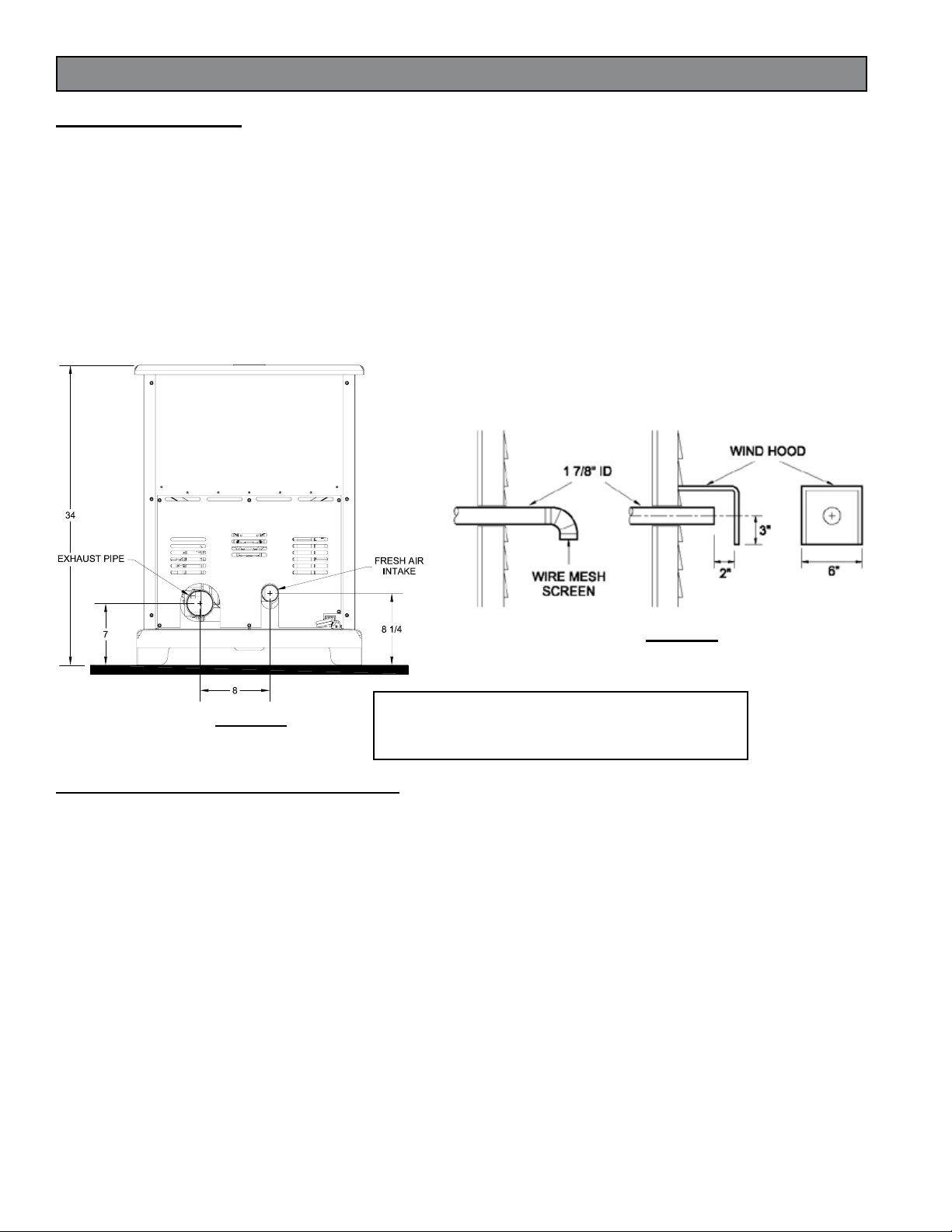
OUTSIDE AIR SUPPLY (optional)
Dependingonyourlocationandhomeconstruction,outsideairmaybenecessaryforoptimalperformance.
Metalpipe(solidorexible)mustbeusedfortheoutsideairinstallation.PVCpipeisNOTapprovedandshouldNEVER
beused.
Awindshieldovertheterminationoftheoutsideairpipeora90-degreeelboworbendawayfromtheprevailingwinds
MUSTbeusedwhenanoutsideairpipeisinstalledthroughthesideofabuilding.TheoutsideairterminationMUST
beatleast1-footawayfromtheexhaustsystemtermination.
TheoutsideairpipeonyourKing/Ashley stoveis17/8”OD.Theoutsideairconnectingpipemustbeatleast17/8”ID.
TheoutsideairconnectionusedMUSTNOTrestricttheamountofairavailabletoyourstove.Theoutsideairconnecting
pipemustbeasshortandfreeofbendsaspossible,anditmusttover,notinside,theoutsideairconnectiontothestove.
NOTE: Dimensions from the oor to your stoves
inlet/exhaust pipes are approximate and may vary
dependingonyourinstallation.
FIGURE 9
TYPICALFRESHAIRTERMINATION
FIGURE 8
EXHAUST/INLETLOCATIONS
SPECIAL MOBILE HOME REQUIREMENTS
MUST BE MAINTAINED.
In addition to the previously detailed installation requirements, mobile home installations must meet the following
requirements:
Thestovemustbepermanentlyattachedtotheoor.
Thestovemustbeelectricallygroundedtothesteelchassisofthemobilehomewith8GAcopperwireusinga
serratedorstarwashertopenetratepaintorprotectivecoatingtoensuregrounding.
Ventmustbe3or4-inch“PL”Ventandmustextendaminimumor36-inchesabovetherooineofthemobilehome
andmustbeinstalledusingaUL/ULClistedceilingrestopandraincap.
Whenmovingyourmobilehome,allexteriorventingmustberemovedwhilethemobilehomeisbeingrelocated.
Afterrelocation,allventingmustbereinstalledandsecurelyfastened.
OutsideAirismandatoryformobilehomeinstallation.Seeyourdealerforpurchasing.
Checkwithyourlocalbuildingofcialsasothercodesmayapply.
•
•
•
•
•
•
USSC 11
How your stove works
YourKing/Ashley stoveutilizesainclinedaugerfuelfeedsystemthatisoperatedbyamicroprocessorcontrolleddigital
circuitboard.Thedigitalcircuitboardallowstheinclinedaugerfuelfeedsystemtoruninatimer-based,non-continuous
cycle;thiscyclingallowstheaugertorunforapredeterminedperiodofseconds.Theaugerpushespelletsupachute
locatedatthefront/bottomofthehopperwhichinturnfallsthroughanotherchuteintotheburnpot.Yourstoveisequipped
withanautomaticignitionsystemthatshouldignitethefuelwithin5-10minutesfrompressingtheONbutton.Aspellets
entertheburnpotandignite,outsideairisdrawnacrossthefuelandheatedduringthecombustionprocesswhichis
thenpulledthroughtheheatexchangerbytheexhaustmotorordraftfan.Asthestoveheatsup,roomairiscirculated
aroundtheheatexchangerbymeansofaroomairblower,distributingwarmairintotheroom.
Theamountofheatproducedbythestoveisproportionaltotherateofthefuelthatisburned,andthisrateiscontrolled
bythe“HEATRANGE”setting.Inordertomaintaincombustionofthefuelatadesiredrate,theairprovidedtotheburn
chamberbytheexhaustordraftfanmustbemaintainprecisely.Toolittleairwillresultinaamethatisnon-energetic
orlazy.Ifthefuelcontinuestoowwithtoolittleairforlongenough,theburnpotwillllwithtoomuchfuelandthere
willsmotherout.Tomuchairwillresultinaamethatisoveractiveoraggressive.Theameinthissituationistypically
veryblueatthebottomandresemblesablowtorch.Ifthissituationcontinues,thefuelintheburnpotwillbeconsumed
andtherewillgoout.
Matchingtheamountofairrequiredforpropercombustiontothefuelrateistheprimaryobjectiveineffectivelyburning
pelletsofvariousbrandsandqualitiesinyourstove.Theairtofuelratiocanbeadjustedtoallowalmostanyfuelquality
toburneffectivelybyfollowingtheproceduresdetailedintheremainderofthismanual.
Becauseaforceddraftpressureisrequiredforthecombustionprocessinsideyourstove,itisextremelyimportantthat
theexhaustsystembeproperlyinstalledandmaintained.And,thatwhenoperatingyourstove,youmakesurethatthe
viewingdoorisproperlysealed.
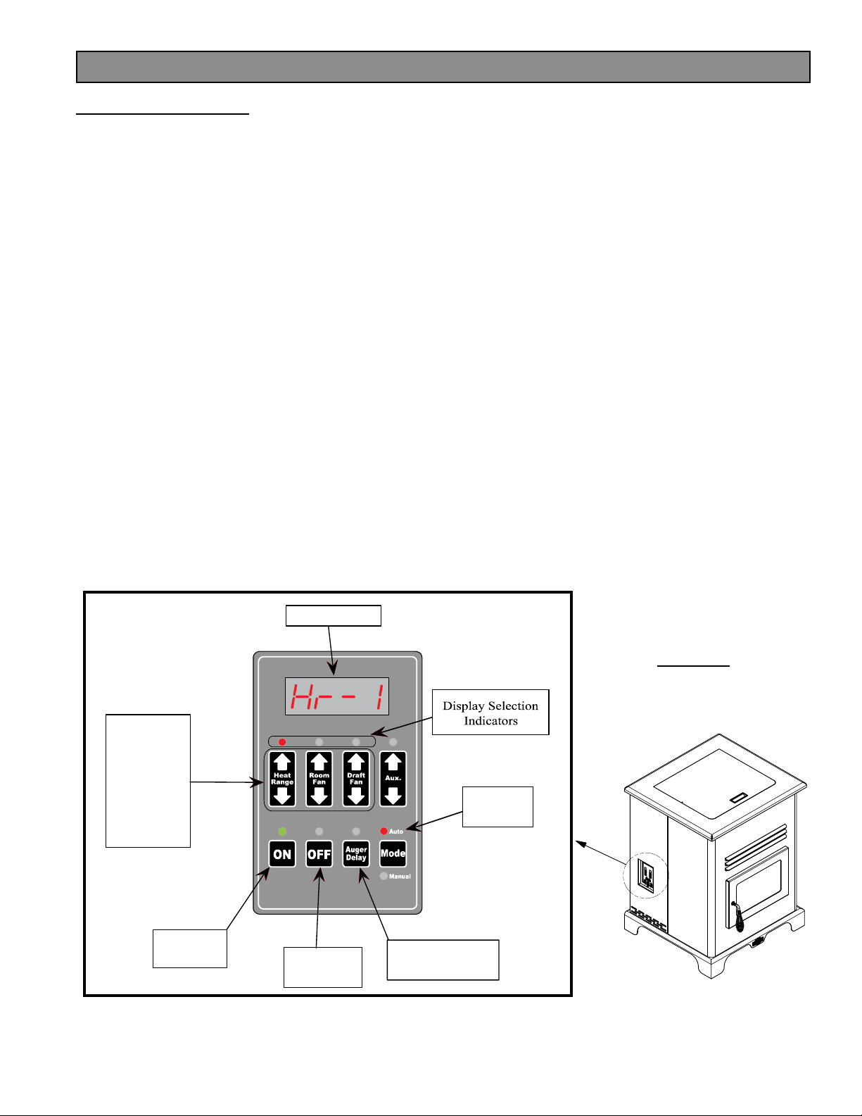
Understanding your stove
4 Digit Display
Up / Down
Buttons :
Heat Range
Room Fan
Draft Fan
Auto Mode
Indicator
Auger Delay
Indicator & Button
Off Indicator
& Button
On Indicator
& Button
FIGURE 10
DIGITALCONTROLPANEL

12 USSC
Control Panel Overview
ON/OFF
Pressingthe“ON”buttononthecontrolpanelwillbeginthestart-upsequencefortheheater.Fuelwillbeginto
feedthroughtheaugerfeedsystemafter3minutes.Pressingandholdingthe“ON”buttonwillrotatetheauger
continuouslyuntilbuttonisreleased,whichfeedsadditionalfuel.
Pressingthe“OFF”buttononthecontrolpanelwillcausetheheatertoenteritsshut-downsequence.Thefuel
feedsystemwillstoppullingfuelfromthehopperand,oncetheregoesoutandtheheatercoolsdown,thefans
willstoprunning.
HEAT RANGE
Pressingthe“HeatRange”arrows,upordown,willadjusttheamountoffuelbeingdeliveredtotheburnpot.
DRAFT FAN
Thedraftfan(exhaust)willcomeonassoonasthe“ON”buttonispressed.Thefanwillautomaticallyadjustits
speedinaccordance
totheheatrangesetting.However,thisspeedcanbemanually
operatedbypressingthe
“DraftFan”arrowsupordown.“DraftFan”whenpressed,thedisplaywillshow“Df-A”,whichisautomatic.Press
thearrowsagaintoadjustfanspeed.Whentheheaterisinthemanualmode,theoptionalthermostatwillnot
properlycontroltheunit.WhenadjustingtheDraftFansetting,tryonly1settingaboveorbelowtheheatsetting.It
isbettertoleavethestoveintheautomaticmode.
ROOM FAN
Theroomfanwillcomeononcetheunithasreachedoperatingtemperature.Bypressingthe“RoomFan”buttons,
thedisplaywillshow“Rf-A”whichisautomaticor“Rf-1”through“Rf-9”formanualsettings.Inautomode,theroom
fan’sspeedwillautomaticallybeadjustedinaccordancewiththeheatrangesetting.Bypressingthe“RoomFan”
uparrow,youcanadjustthefanspeedsettingupto“Rf-9”.Theroomfanmustoperateatalevelgreaterthanor
equaltotheheatrangesetting.
AUX-USEDTORETURNTHESTOVETOTHEFACTORYSETTINGS
Toreturnthestovetoit’soriginalfactorysettings,pressandholdtheAUXUPandAUXDOWNbuttonssimultaneously
for3seconds.
AUGER DELAY
The“AugerDelay”buttoncanbeusedtopauserotationoftheAugerforapprox.1minute.Thiscanbecancelledby
pressingthe“ON”button.The“AugerDelay”isnormallyusedonlyduringthestartupcycletoslowthefueldelivery
downduringtheinitialignition.
MODE
The“Mode”buttonisusedtoswitchbetweenmanualandautomaticmode.Wheninautomode,thefansandauger
willoperateatpresetintervalsunlesschangedmanuallyusingthebuttonsmentionedabove.Wheninmanualmode,
thedraftfan(exhaust)willoperateatfullspeed(100%).
Duringnormaloperation,theunitisconstantlymonitoredforproblems.Intheeventofanerrorcondition,theunit
willstopandanerrorwillbedisplayed.Seethelistoferrorcodesfoundattheendofthismanual.
TurningtheheaterON/OFF,aswellasadjustmentsforthefuelfeedrateandroomfanspeedareperformedbypressing
theappropriatebutton(s)onthecontrolpanelwhichislocatedonthelowerleft-handsideofyourheater.
Thisunitcanbechangedbetweenanautomaticoperationoramanualoperation.Thecontrollercomesdefaultinthe
automaticmode.

USSC 13
UNIT PREPARATION
Aftercarefullyunpackingandreadingtheinstructionsforinstallingyourstove,youwillneedtoperformthefollowingsteps:
Attachtheincludedspringhandletothedoorhandlebyscrewingitoninarespectivelocation.
Attachtheelectricalcordtothebackofthestoverst;thenplugitintoa110-voltoutlet(anoutletsurgeprotectoris
highlyrecommended).
PERFROMING AN INTIAL TEST
Thistestisusedatthefactorywherethestovesareassembledtotestthefunctionalityofthecontrolandthestove
beforetheunitisshipped.Toperformthistest,pressandholdtheOFFandAUGERDELAYbuttonssimultaneouslyfor
3seconds.Toadvancethroughthetest,pressanykeyunlessotherwisenotedintheteststep.
ExhaustFanOutputTest–Thedisplaywillshow“drft”.Theexhaustfanisturnedonfullthenreducedtoaleveljust
abovethetypicalminimumpressureswitchsetting.TheONLEDindicateswhetherthepressuresensorisdetected.
Ifthepressureswitchisnotdetected,thefanrampstofullonfortwosecondsthenreturnstothepreviouslyestablished
levelifthepressureswitchcloses.IftheDraftFanFuseisnotblownandthefusedetectioncircuitisfunctioning,
theDraftFanLEDwillbelitandtheotherthreetoprowLEDswillbeoff.
RoomFanOutputTest-Thedisplaywillshow“rfan”.Theroomfanisturnedonfull.IftheRoomFanFuseisnot
blownandthefusedetectioncircuitisfunctioning,theRoomFanLEDwillbelitandtheotherthreetoprowLEDs
willbeoff.
IgnitorOutputTest-Thedisplaywillshow“ignt”.Theignitormotoristurnedonfull.IftheIgnitor(AUX)Fuseisnot
blownandthefusedetectioncircuitisfunctioning,theAuxLEDwillbelitandtheotherthreetoprowLEDswillbeoff.
AugerOutputTest-Thedisplaywillshow“augr”.Theaugermotoristurnedonfull.IftheAugerFuseisnotblown
andthefusedetectioncircuitisfunctioning,theHeatRangeLEDwillbelitandtheotherthreetoprowLEDswillbeoff.
HopperSwitchTest–Thedisplaywillshow“hppr”.The“ON”LEDislit.Ifthehopperswitchisopen(lidisopen),
the“HEATRANGE”LEDwillturnon.Ifthelidisclosed,the“HEATRANGE”LEDwillbeoff.
ThermostatInputTest–Thedisplaywillshow“stat”.Ifthethermostatinputisclosed,theONLEDwillturnon,
otherwiseitwillbeoff.
FluegasThermistorTest–ThedisplaywillshowtheuegastemperatureindegreesF.
ACFrequencyTest-DisplaysthemeasuredACFrequencyinhertzfollowedbytheletter‘H’.
WatchdogReset–Thewatchdogtimeristestedtoensurethattheboardcanbereset.Themessage“BYE”is
displayeduntilthewatchdogresetstheboard.
Operation
1.)
2.)
3.)
4.)
5.)
6.)
7.)
8.)
9.)
PERFORMING A “DRY RUN”
Performa“dryrun”onyourstovepriortomakingtheexhaust/inletconnectionsandstartingyourstoveforthersttime.
CheckthatthereisNOfuelorANYforeignmaterialinthehopperorburn-pot.
Checkthattheviewingdoorandhopperlidissecurelyclosed.
Pressthe“ON”buttononthecontrolpanel.VerifythattheONLEDislit(blinking)andthedisplayshowsHR-1.Also
theLEDabovetheHEATRANGEandtheAUTOMODEindicatorshouldbelit.IfanyotherLED’sarelitorashing,
consultthe“DisplayIndicators”inthismanual.
Youshouldheartheexhaust(draft)fanrunningimmediatelyandtheaugershouldbeginturningcontinuouslyfor1
minute.
Theautofuelignitor(locatedinsidethebackwalloftheburnpot)shouldbegintoglowred/orangeafter3minutes.
TheRoomFanwillnotoperateatthistimesincetheunitmustreachafactorypresettemperature.
DONOTopentheviewingdoor,thewillgetveryhotduringthistest.Thestovewillautomatically
shutdownafterapproximately23minutes.
1.)
2.)
3.)
4.)
5.)
6.)

14 USSC
SHUT DOWN PROCEDURE
Pressthe“OFF” buttononthecontrolpadtoputthestoveinshutdownmode.Atthistime,theredlightabovethepad
willilluminate.Oncethisisdone,theaugerwillstopfeedingpellets,butthedistributionblowerandexhaustblowerwill
continuetooperate.Whentheinternaltemperatureoftheunitdropsbelowthefactorypresettemperature,thedistribution
blowerandexhaustblowerwillceasetooperate.Theredlightwillthenshutoffandtheunitwillbecompletelyshutdown.
Thehottertheunitisduringitsoperation,thelongeritwilltakeforthestovetocompletetheshutdowncycle.Ifthe
stovestaysonformorethan2hoursafterpressingthe“OFF” buttonandyouaresurethatthereisout,thestovecan
beunpluggedfromtheoutlet.Afterapproximately10seconds,theunitcanbere-connectedtothepowersourceand
thecontrolboardwillbereset.
Operation
START-UP PROCEDURE
Verifythatthehopperiscleanandfreeofforeignmatter.
Verifythatalloftherequiredexhaust/inletconnectionshavebeenmadeinaccordancewiththismanualandthat
thestoveispluggedintoanoutlet(anoutletsurgeprotectorishighlyrecommended).
Fillthehopperwithwoodpellets;donotallowanypartofthebagoranyotherforeignmaterialintothehopper,as
thismayjamtheauger.
Ensurethatallpelletmatterisclearedfromthehopperseatingsurface.
Closethehopperlid.
Makesurethattheviewingdoorissecurelyclosed(thesafetypressureswitchwillnotallowthestovetofeedfuel
ifthereisnodraftpressureinsidethestove).
Pressthe“ON” buttononthecontrolpadandsetthe“HEAT SETTING” toyourdesiredsetting.
Thestovewillbegintofeedfuelandthewillignitethefuelinapproximately5minutes.
Onceaconsistentamehasbeenestablished,youcanadjustthe“HEATRANGE”and“BLOWERSPEED”onthecon-
trolpadtoyourdesiredsettings.(Note:Thedistributionblowerwillnotfunctionuntiltheheatexchangerinthestove
reachesthefactorypresettemperature).
1.)
2.)
3.)
4.)
5.)
6.)
7.)
8.)
Adjustthe“HEAT RANGE” and“BLOWER SPEED” toa“3” settingandallowthestove
tooperateinthismannerforapproximatelythree(3)hours(ormoreifnecessary),allowingthestoveto
“cureout”asthepaintandoilsfromthemanufacturingprocessburnoff.Werecommendthatyouopen
doorsandwindowsinyourhomeduringthisprocess.Adjustsettingtodesiredsetting.

USSC 15
Maintenance
Operation
DAILY OPERATION
Thisunitshouldbelledwhenthehopperleveldropsbelow3-inches.
Intheeventofa,thestoveWILLNOTfunction.Itisveryimportantthatunitbeventedproperly(with
outsideair),asthenaturaldraftisneededtoclearthesmokefromthestoveduringapoweroutage.Iftheunitwas“ON”
whenthepoweroutageoccurred,oneofthefollowingwilltakeplace:
Ifthestoveisstillwarm,itwillresumefeedingfuelandcontinuetooperatenormally.Iftherehasgoneout,you
willhavetopressthe“OFF” buttonandthenthe“ON” buttonagaintobeginanewstart-upsequence.
Ifthestovehascooled-off,itwillresettoits“OFF” condition.Atthispoint,youmaypressthe“ON” buttonandthe
unitwillbeginanewstart-upsequence.
NOTE:Theunitwillalsoshutdownintheeventofanexhaustblowerfailure;ifthisisthecase,theunitwillnotre-start
andyoumustcontactCustomerServiceat(800)750-2723.
SAFETY AND CONVENIENCE FEATURES
YourKing/Ashley incorporatesathathelpsensurethateverythingisinproperworkingorder
beforefeedingfueltotheburnpot.Becausethestoveworksusinganinduceddraftpressure,thestovewillnotcontinue
tooperateiftheviewingdoorisleftopen;oriftheexhaustblowerfailsortheexhaustsystemisblocked.
Thewillpreventyourstovefromoperatingatabnormallyhightemperatures.Shouldthestove
temperaturebegintoapproachthefactorypre-setlimit,thetemperaturelimitcontrolwillautomaticallyslowdownthe
augerfeedrateuntilthetemperaturereturnstoanormalcondition.Eventhoughtheheaterwilloperateonsetting“5”
(HI),werecommendtooperateyourheateronthissettingforonlyashortperiodoftime.(1houretc.)
YourKing/Ashley stovealsoincludesanasastandardfeature.Theuseofotherrestartermaterials
(woodchips,startergel,etc.)isnotnecessary.Bysimplypressingthe“ON”buttononthedigitalcontrolpanel,your
stovewillbegintofeedfuelandautomaticallystartwithin5minutes.
1.)
2.)
EXHAUST SYSTEM
Thebyproductsofcombustioncontainsmallparticlesofyash.Flyashwillcollectintheexhaustventingsystemand
restricttheowofuegases.Incompletecombustion,suchasduringstartup,shutdown,orincorrectoperationofthe
stovewillleadtosootformationwhichwillcollectintheexhaustsystem.Therefore,itisimportantthattheexhaust
systembeduringtheburningseason.
Checkthecleanoutteesperiodicallytodeterminetherequiredcleaningschedule.3or4-inchchimneybrushesare
availableforchimneycleaning.Iftheexhaustsystemoroutsideairpipeshavescreensonthem,frequentlycleanthe
screen.Apluggedscreenwillshutoffcombustionairandcausearetodieorburnpoorly.

16 USSC
INTERIOR CHAMBERS
Periodicallyremoveandcleantheburnpotandtheareainsidetheburnpothousing.Inparticularitisadvisabletoclean
outtheholesintheburnpottoremoveanybuildupthatmaypreventairfrommovingthroughtheburnpotfreely.Remove
thetwo(2)platesoneachsideoftheburnpothousingandcleanoutthatrearchamber.
Ifavacuumisusedtocleanyourstove,wesuggestusingavacuumdesignedforashremoval.Someregularvacuum
cleaner(i.e.shopvacs)mayleakashintotheroom.
ASH DISPOSAL
Ashesshouldbeplacedinametalcontainerwithatightttinglid.Theclosedcontainerofashesshouldbeplacedon
anoncombustibleoororontheground,wellawayfromallcombustiblematerials,pendingnaldisposal.Iftheashes
aredisposedofbyburialinsoilorotherwiselocallydispersed,theyshouldberetainedintheclosedcontaineruntilall
cindershavebeenthoroughlycooled.
Checkthehopperperiodicallytodetermineifthereisanysawdustorpelletsthatarestickingtothehoppersurface.
Cleanasneeded.
Inspectthemaindoorandglasswindowgasketsperiodically.Themaindoormayneedtoberemovedtohavefrayed,
broken,orcompactedgasketsreplacedbyyourAuthorized“King/Ashley”Dealer.Theglassgaskethasagapatthe
bottomfortheairwash.
BLOWER MOTORS
Cleantheairholesonthemotorsofboththeexhaustanddistributionblowersannually.Removetheexhaustblower
fromtheexhaustductandcleanouttheinternalfanbladesaspartofyourfallstart-up.
PAINTED SURFACES
Paintedsurfacesmaybewipeddownwithadampcloth.Ifscratchesappear,oryouwishtorenewyourpaint,contact
yourAuthorized“King/Ashley”Dealertoobtainacanofsuitablehigh-temperaturepaint.
GLASS
Werecommendusingahighqualityglasscleaner.Shouldabuildupofcreosoteorcarbonaccumulate,youmaywish
touse000steelwoolandwatertocleantheglass.Intheeventyouneedtoreplacetheglass,onlyhightemperature
ceramicglassofthecorrectsizeandthicknessmaybeused.ContactyourAuthorized“King/Ashley”Dealertoobtain
thisglass.
FALL START UP
Priortostartingtherstreoftheheatingseason,checktheoutsideareaaroundtheexhaustandairintakesystems
forobstructions.Cleanandremoveanyyashfromtheexhaustventingsystem.Cleananyscreensontheexhaust
systemandontheoutsideairintakepipe.Turnallofthecontrolsonandmakesurethattheyareworkingproperly.This
isalsoagoodtimetogivetheentirestoveagoodcleaningthroughout.
SPRING SHUTDOWN
Afterthelastburninthespring,removeanyremainingpelletsfromthehopperandtheaugerfeedsystem.Scoopout
thepelletsandthenruntheaugeruntilthehopperisemptyandpelletsstopowing(thiscanbedonebypressingthe
“ON” buttonwiththeviewingdooropen).Vacuumoutthehopper.Thoroughlycleantheburnpot,andrebox.Itmay
bedesirabletospraytheinsideofthecleanedhopperwithanaerosolsiliconesprayifyourstoveisinahighhumidity
area.Theexhaustsystemshouldbethoroughlycleaned.
YEARLY SERVICING
AyearlyservicingandcleaningbyyourAuthorized“”Dealerisrecommended.Afeemaybechargedfor
thisservice.
Maintenance
USSC 17
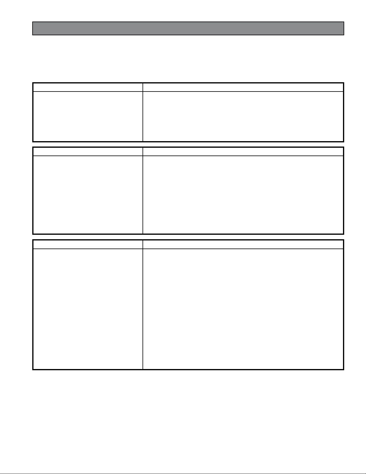
Trouble Shooting
PROBLEM CAUSE:Torichair/fuelmixture
Orange, lazy flame_excessive fuel
build-upintheburnpot
Cleanouttheburnpotandburnpothousing
Makesurethattheviewingdoorisclosedandsealedproperly.Ifnot,
adjustdoorcatchand/orreplacedoorgaskets.
Checkthatalloutsideconnectionsareclearofanyobstructions.
Checktheexhaustsystem;cleanasneeded.
PROBLEM CAUSE:Burnpotburnsoutoffuel
Firegoesoutorstoveshutsdown. Hopperisempty,rellthehopper.
Lossofdraftpressure.Makesurethattheviewingdoorisclosedand
sealed properly. If not,adjust door catch and/or replace door gaskets.
Checkthatalloutsideconnectionsareclearofanyobstructions.Check
theexhaustsystem;cleanasneeded.
Checkthatthepressureswitchconnectiontothereboxisfreeofashor
clearofobstructions.
Augersystemisjammedorthereisa“bridging”ofthefuelinthehopper,
preventingfuelfromowingintotheaugerfeedsystem.
PROBLEM CAUSE:Auto-StartIgniterfailstoignitethefuelintheburnpot.
Stove does not start are whenthe
“ON”buttonispushed
Turnthestove“OFF”.Cleartheunburntfuelfromtheburnpotandtry
again.
Checkthepelletquality.Replaceifmoist,wet,ordirty.
Lossofdraftpressure.Makesurethattheviewingdoorisclosedand
sealed properly. If not,adjust door catch and/or replace door gaskets.
Checkthatalloutsideconnectionsareclearofanyobstructions.Check
theexhaustsystem;cleanasneeded.
Checkthat the auto-startigniteris not blockedwithash or soot.(The
igniterislocatedbehindtheburnpotonthebackwalloftherebox.)
Checkthatthepressureswitchconnectiontothereboxisfreeofashor
clearofobstructions.
Theauto-startignitergets“redhot”duringstart-up.Ifyoucannotvisibly
seethe igniter glowingduring start-up, thenthe igniter may need to be
replacedorthereisaproblemwiththeelectricalcontrolsystem.
18 USSC
Error
Code
Err1
Err2
Err3
Err4
Err5
Err6
Err7
Err8
Error
Descrption
Thehighlimittemperaturesensor
hastripped.
Stoveranoutoffuelduringnormal
operation.
The stove was unable to reach the
RoomFanOntemperaturewithinthe
startuptime.
Thepowerfailedwhilethestovewas
hot, and when power was restored,
therewasout.
TheAugeroutputfusehasblown.
TheIgnitoroutputfusehasblown.
The Draft Fan (Exhaust Fan) output
fusehasblown.
TheRoomFanoutputfusehasblown.
Possible
Causes
• Inadequateventilation.
• Roomfanfailure.
• ExhaustBlockage.
• ElectricalOpenintheovertemperatureswitchorwiring.
• HopperEmpty.
• Augeroutputfailureorjam.
• Flameoffuelqualitycausedretoburntooslowlyorgoout.
• ElectricalOpeninlowtemperatureswitchorwiring.
• FlameorFuelqualitycausedtheretoburntooslowlyorgo
out.
• AugeroutputfailureorjamHopperemptyonstartup.
• ElectricalOpeninlowtemperatureswitchorwiring.
• Powerloss
• Augermotorjammedorbad.
• Ignitorshortedoutorbad.
• DraftFanmotorjammedorbad.
• Roomfanmotorjammedorbad.
Severalsituationsoreventsareindicatedinnormaloperationbyblinkingdisplayindicatorsorsegmentsinthedisplay:
Thismeansthatthestoveisinthe“StartUp”statewaitingforeithera3minutetimeouttobegin
burningorforthestovetoreachthewarmtemperaturewhichevercomesrst.
Thisindicatesthatthestoveisinthe“Shutdown”statewaitingfortheOFFbutton,orfora15
minuteperiodafterthestovewasturnedoff,orforthestovetocooldown,orforthedoortobeclosed.
Thisindicatesthatthestoveisinthenormalrunmodeandisrampingfrom
thecurrentheatrangesettingtothetargetheatrangesetting.Oncetherampiscomplete,thedashwillstopashing.
Forrampingfromheatrange1to5,thedefaulttimeis12minutes(witha90secondramptime).
Thisindicatesthatthestoveisinnormaloperationandisrunningintheautomatic
mode.However,eithertheDraftFanorAuxiliarysettingismanuallycongured.
Thisindicatesthatthestoveisinnormaloperationandthatthevacuumsensor
detectsalossofpressureeitherbecausethedoorisopenorbecausethereisanegativepressureintheroomwith
respecttotheexhaust.
Thisindicatesthattheignitorisonduringthelightingstage.
Thisindicatesthatthestoveisin
normaloperationandthatanovertemperatureconditionexistscausingthefueltostop.
Thisindicatesthatthestoveisinacut
backconditioninanattempttopreventanovertemperatureshutdown.
Toreturnthecontroltoitsoriginalfactorydefaultsettings,pressandholdtheAUXUPandAUXDOWNbuttonstogether
forthreeseconds.
Error Codes and Display Indicators
USSC 19
13
5
11
10
1
10
12
10
6
12
7
8
2
4
3
9
9
9
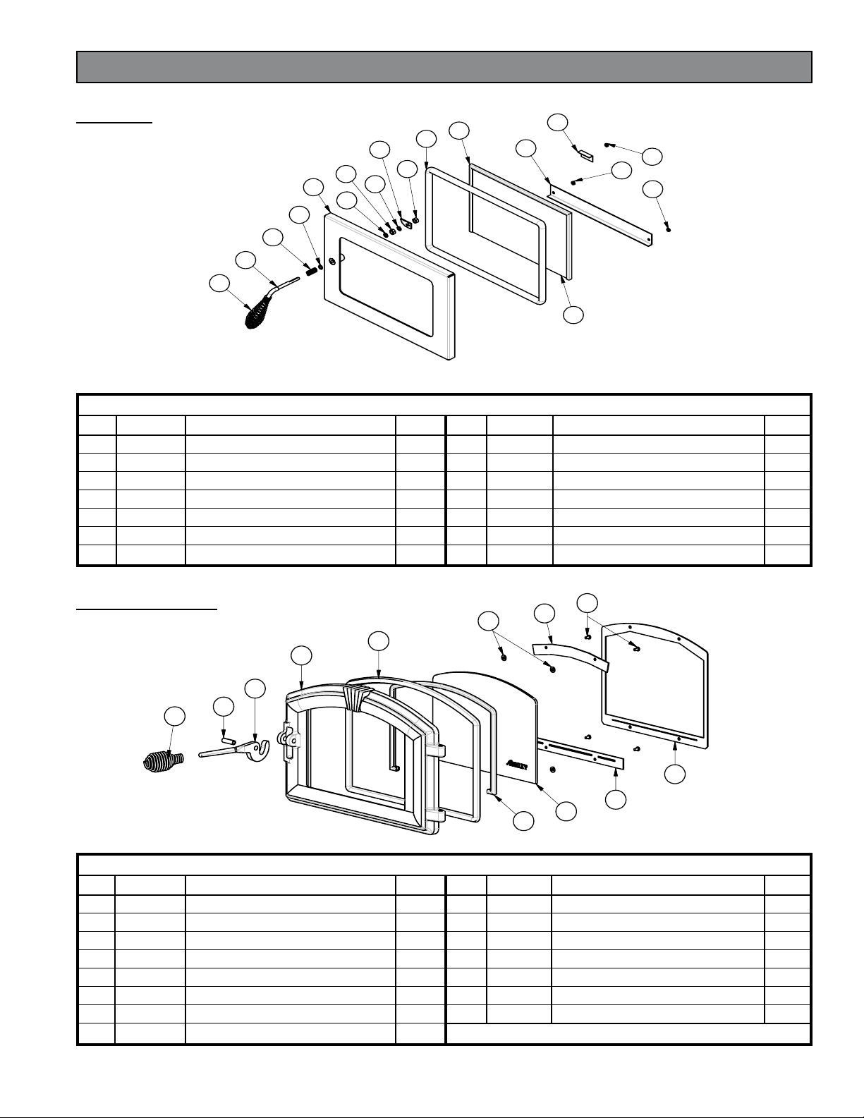
Parts Diagram/List models 5500, 5500M & 5500XL
11
3
2
1
5
6
4
7
9
8
10
12
1 25490 DoorWeldment 1
2 891166 CeramicGlass 1
3 891188 GlassRetainer,Top 1
4 891186 GlassRetainer,Bottom 1
5 25517 Handle,Door 1
6 891168 Latch,Door 1
7 88082 3/4”RopeGasket 4.3ft
PARTSLIST
8 88087 GlassGasket 3.75ft
9 83297 8-32HexNut 3
10 83547 Washer 3
11 83903 Spring 1
12 83546 5/16x18HexJambNut 2
13 891167 SpringHandle 1
1 25507 FeedDoor 1
2 25492 Handle,Door 1
3 83506 3/8x11/4RollPin 1
4 891067 DoorGlassw/AshleyLogo 1
5 88066 5/8”RopeGasket 4.5ft
6 88087 GlassGasket(1x13/16) 3.5ft
7 25520 BottomGlassRetainer 1
8 25521 TopGlassRetainer 1
PARTSLIST
9 83278 Washer 4
10 83202 MachineScrew 4
11 89574 SpringHandle 1
12 25393 Retainer,Glass
(AlternateFor7&8) 1
N/S 25080MB DoorLatch 1
N/S 83508 5/16-18x1-3/4Bolt 1
N/S 83338 5/16-18Lock-Nut 1
N/S-NotShown
20 USSC
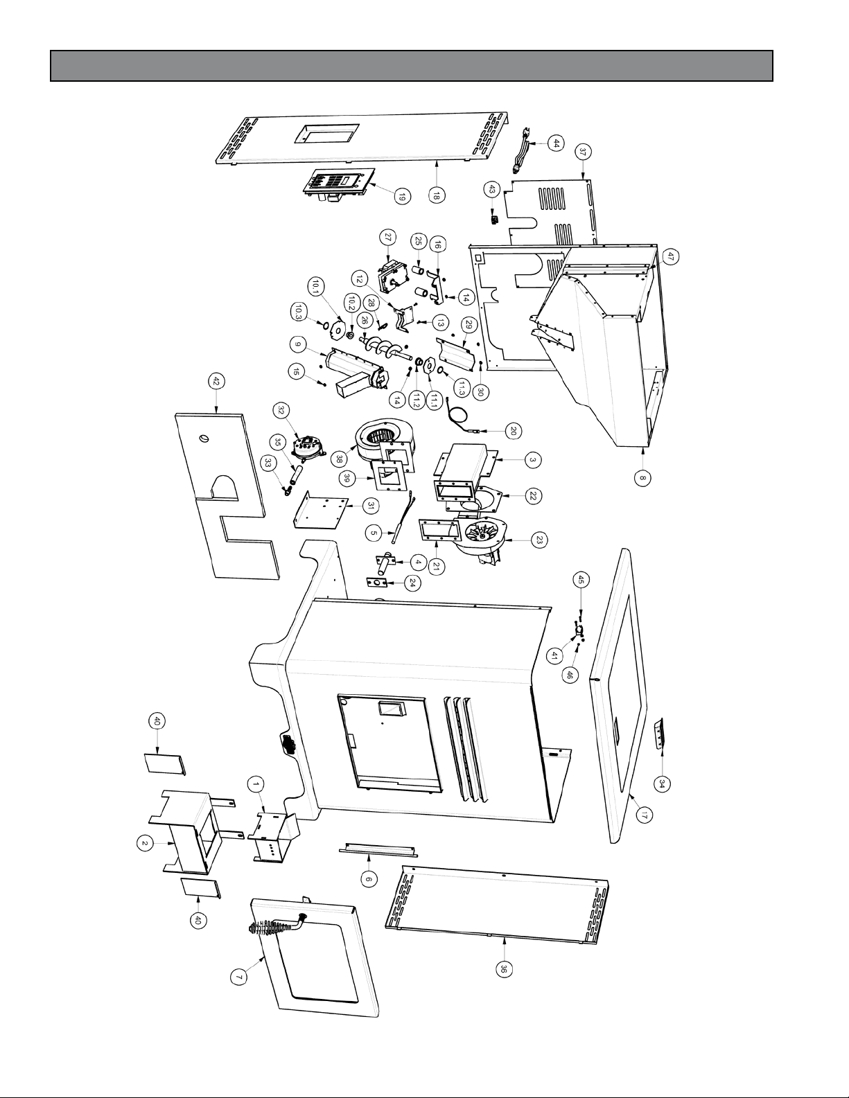
Parts Diagram model 5500, 5500M and 5500XL
Note: All repair parts (other than Cabinet Sides, Hopper Assy., and Door Assy.) are same for models 5500, 5500M and 5500XL.
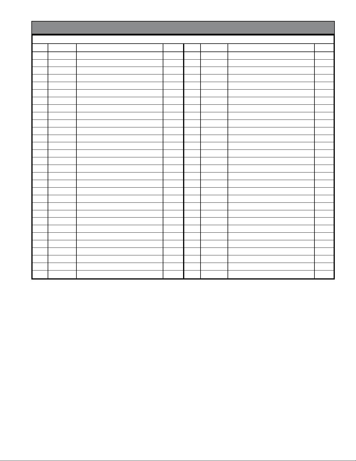
USSC 21
Parts List model 5500/5500M/5500XL
1 86624 BurnpotAssembly 1
2 86625 HousingAssy,Burnpot 1
3 86628 Weldment,ExhaustDuct 1
4 86633 Weldment,IgniterTube 1
5 80481 IgniterCartridge 1
6 25506 Weldment,DoorHinge 1
7 69512 DoorAssembly 1
8 69518 HopperAssembly(5500) 1
- 69522 HopperAssembly(5500XL) 1
9 891164 WeldmentAugerHousing 1
10 69513 Assy.,BushingRetainerBottom 1
10.1 891190 Plate,BottomBushing 1
10.2 891132 Bushing 1
10.3 83534 Retaining Ring 1
11 69514 Assy.,BushingRetainerTop 1
11.1 891189 Plate,TopBushing 1
11.2 891132 Bushing 1
11.3 83534 Retaining Ring 1
12 891161 Weld.,Bot.PlateRetainer 1
13 83543 6-32x3/8MachineScrew 2
14 83356 10-32HexNut 4
15 83299 6-32HexNut 2
16 891195 Bracket,DriveMotor 1
17 25498 Weldment,TopLid 1
18 25511 Weld,LeftSideCabinet(5500) 1
- 25515 Weld,LeftSideCabinet(5500XL) 1
19 80558 CircuitBoardAssembly 1
20 80480 Thermistor 1
21 88117 Gasket,ExhaustDuct 1
22 88100 Gasket,ExhaustBlower 1
PARTSLIST
23 80473 Blower,Exhaust 1
24 88118 Gasket,IgniterFlange 1
25 891169 Hose,Heater 1.5in
26 891141 Auger 1
27 80488 DriveMotor 1
28 83529 Hairpin 1
29 891180 Cover,Auger 1
30 83297 8-32HexNut 4
31 891187 Bracket,PressureSwitch/PCB 1
32 80549 PressureSwitch 1
33 89586 Nipple 1
34 891148 Handle,Plastic 1
35 891121 SiliconeTube 3in.
36 25512 Side,RightCabinet(5500) 1
- 25516 Side,RightCabinet(5500XL) 1
37 25510 Panel,Access 1
38 80472 Blower,Distribution 1
39 88106 Gasket,DistributionBlower 1
40 25513 Cleanout,Ash 2
41 80491 Microswitch 1
42 88119 Insulation,Blanket 2
43 80462 Receptacle,3Prong 1
44 80461 PowerSupplyCord 1
45 83516 #4-40MachineScrew 2
46 83542 #4-40NylonLockNut 2
47 89390A RubberGrommet 1
N/S 80548 WiringHarness 1
22 USSC
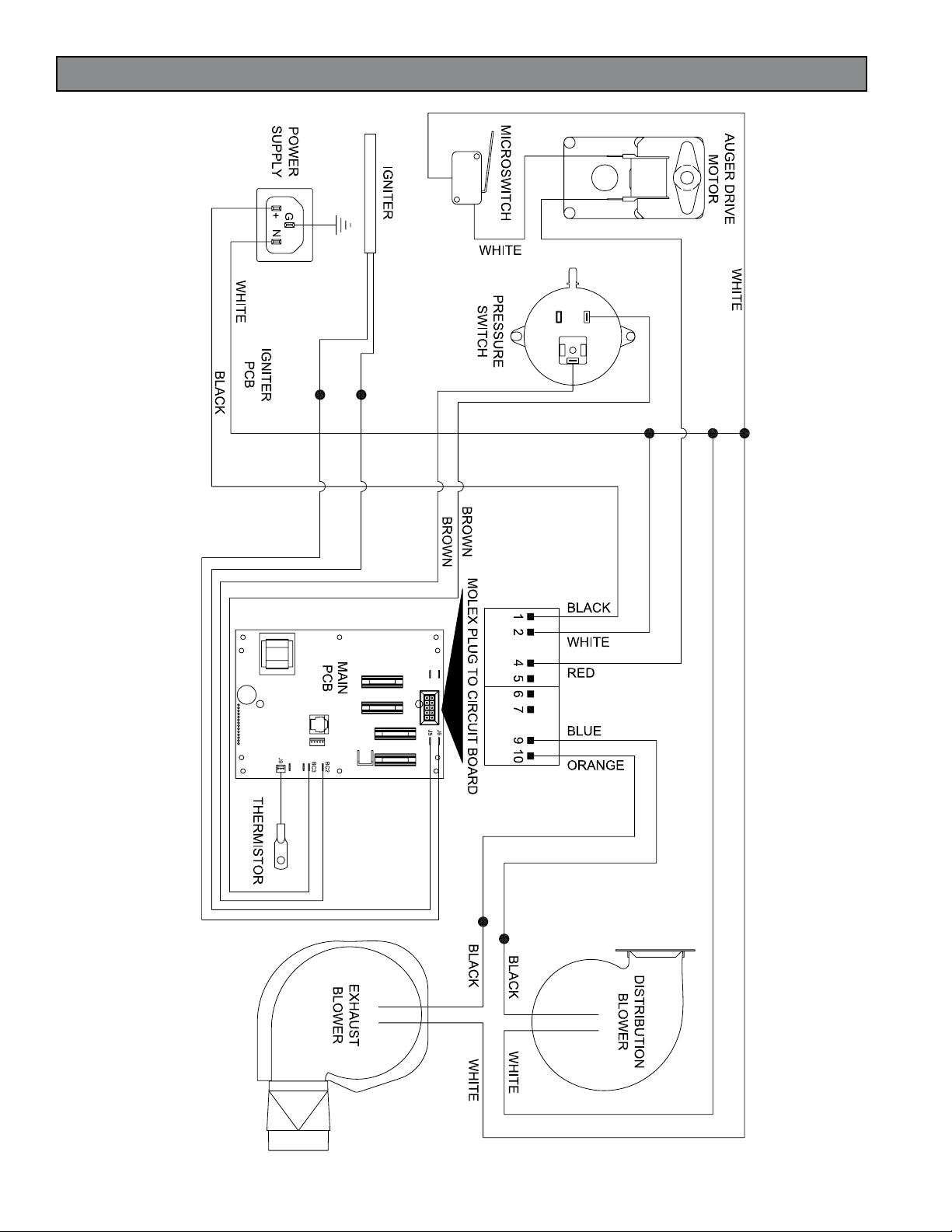
Wiring Diagram
GRAY
BLACK
USSC 23
Notes

24 USSC
THIS MANUAL WILL HELP YOU OBTAIN EFFICIENT, DEPENDABLE SER-
VICE FROM YOUR KING OR ASHLEY, AND ENABLE YOU TO ORDER REPAIR
PARTS CORRECTLY.
KEEP THIS MANUAL IN A SAFE PLACE FOR FUTURE REFERENCE.
WHEN WRITING, ALWAYS GIVE THE FULL MODEL NUMBER WHICH IS ON
THE NAMEPLATE ATTACHED TO THE HEATER.
WHEN ORDERING REPAIR PARTS, ALWAYS GIVE THE FOLLOWING INFOR-
MATION AS SHOWN IN THIS LIST:
1. THE PART NUMBER
2. THE PART DESCRIPTION
3. THE MODEL NUMBER: 5500 5500M 5500XL
4. THE SERIAL NUMBER:____________________
How to order repair parts
United States Stove Company
227 Industrial Park Road
P.O. Box 151
South Pittsburg, TN 37380
(800) 750-2723
WWW.USSTOVE.COM
C
S
S
U
C
O
M
P
A
N
Y
U
N
I
T
E
D
S
T
A
T
E
S
S
T
O
V
E