Loading ...
Loading ...
Loading ...
SERVMCE AND ADJUSTMENTS
,i lU.i ............... , .................... ,i,,,i i.. . ........
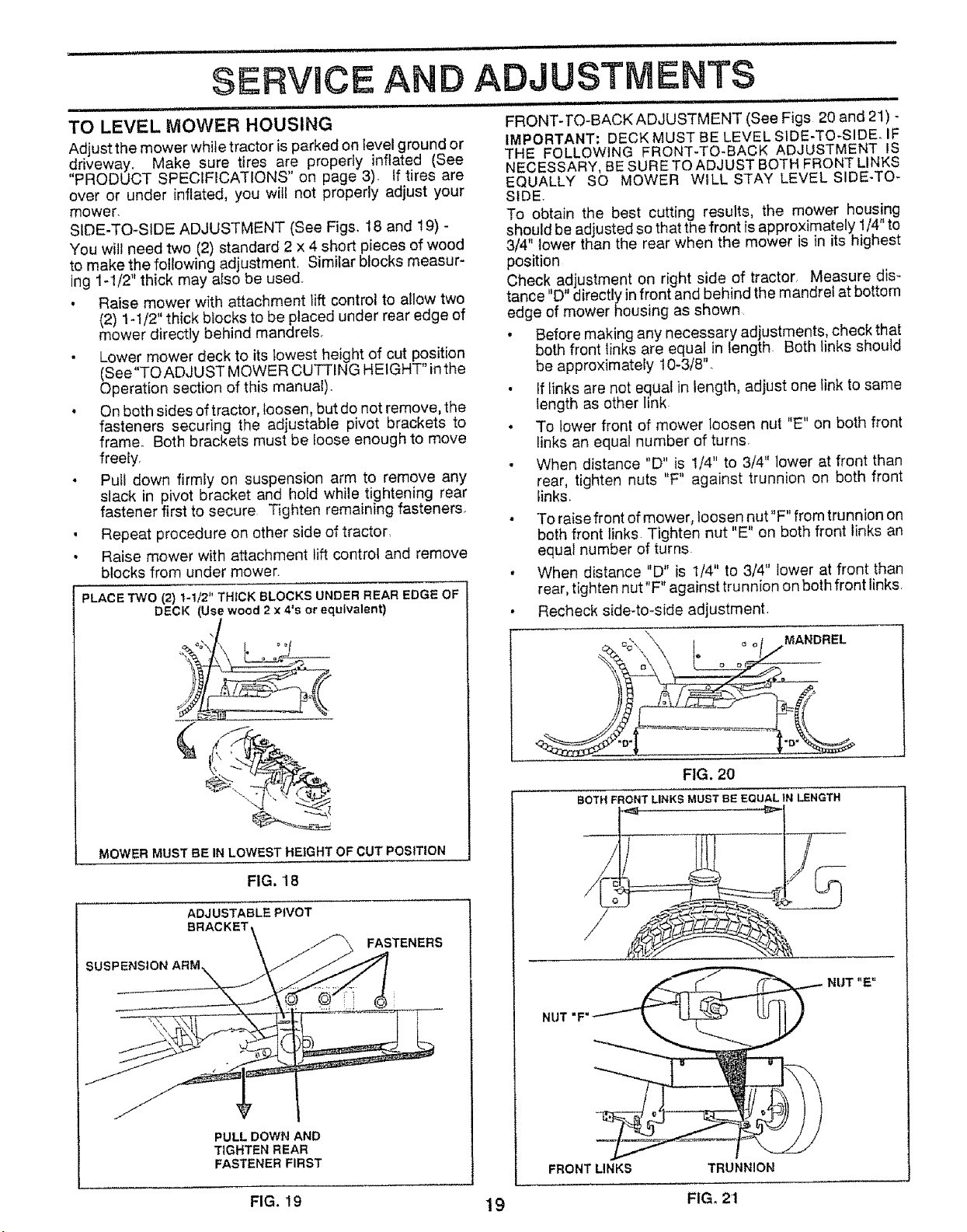
TO LEVEL MOWER HOUSING FRONT-TO-BACKADJUSTMENT (See Figs 20 and 21)-
Adjust the mower while tractor is parked on level ground or IMPORTANT= DECK MUST BE LEVEL S1DE-TO-SIDEo IF
THE FOLLOWING FRONT-TO-BACK ADJUSTMENT IS
driveway. Make sure tires are propedy inflated (See
PRODUCT SPECIFICATIONS' on page 3), If tires are NECESSARY, BE SURE TO ADJUST BOTH FRONT LINKS
EQUALLY SO MOWER WILL STAY LEVEL SIDE-TO-
over or under inflated, you wilt not properly adjust your SIDE.
mower. To obtain the best cutting results, the mower housing
SIDE-TO-SIDE ADJUSTMENT (See Figs. 18 and 19) - should be adjusted so that the front is approximately 1/4" to
You will need two (2) standard 2 x 4 short pieces of wood 3/4" lower than the rear when the mower is in its highest
to make the following adjustment, Similar blocks measur- position
ing 1-1/2" thick may also be used. Check adjustment on right side of tractor Measure dis-
, Raise mower with attachment lift control to allow two tance "D" directly in front and behind the mandrel at bottom
(2) 1-1/2" thick biocks to be placed under rear edge of edge of mower housing as shown
mower directly behind mandrel& • Before making any necessary adjustments, check that
• Lower mower deck to its lowest height of cut position both front links are equal in length Both links should
(See"TOADJUST MOWER CUTTING HEIGHT" inthe be approximately 10_3/8".
Operation section of this manual). • If links are not equal in length, adjust one link to same
• On both sides of tractor, loosen, but do not remove, the length as other link
fasteners securing the adjustable pivot brackets to • To lower front of mower loosen nut "E" on both front
frame° Both brackets must be loose enough to move links an equal number of turns.
freely.
• When distance "D" is 1/4" to 3/4" lower at front than
• Pull down firmiy on suspension arm to remove any rear, tighten nuts "F" against trunnion on both front
slack in pivot bracket and hold while tightening rear links.
fastener first to secure Tighten remaining fasteners.
, Repeat procedure on other side of tractor
• Raise mower with attachment _ift control and remove
blocks from under mower.
PLACE TWO (2) 1-1/2" THICK BLOCKS UNDER REAR EDGE OF
DECK (Use wood 2 x 4's or equivalent)
/
_._,_
MOWERMUSTBE INLOWEST HEIGHT OF CUTPOSITION
FIG, 18
ADJUSTABLE PIVOT
BRACKET\
\ j_ FASTENERS
SUSPENSION ARM\ _.j __
PULL DOWN AND
TIGHTEN REAR
FASTENER FIRST
e
To raise front of mower, loosen nut"F" from trunnion on
both front links Tighten nut "E" on both front links an
equal number of turns
When distance "D" is 1/4" to 3/4" lower at front than
rear, tighten nut"F" against trunnion on both front links,
Recheck side-to-side adjustment.
MANDREL
FIG. 20
BOTH FRONT LINKS MUST BE EQUAL tN LENGTH
NUT "E"
FRONT LINKS TRUNNION
FIG. 19 19 FIG, 21
Loading ...
Loading ...
Loading ...