1
2014-01-08 #:125-9484-6 (2017-04-06)
ENG
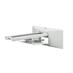
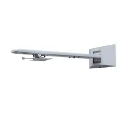
32" - 80"
(81 - 203 cm)
125 lb
(57 kg)
MAX
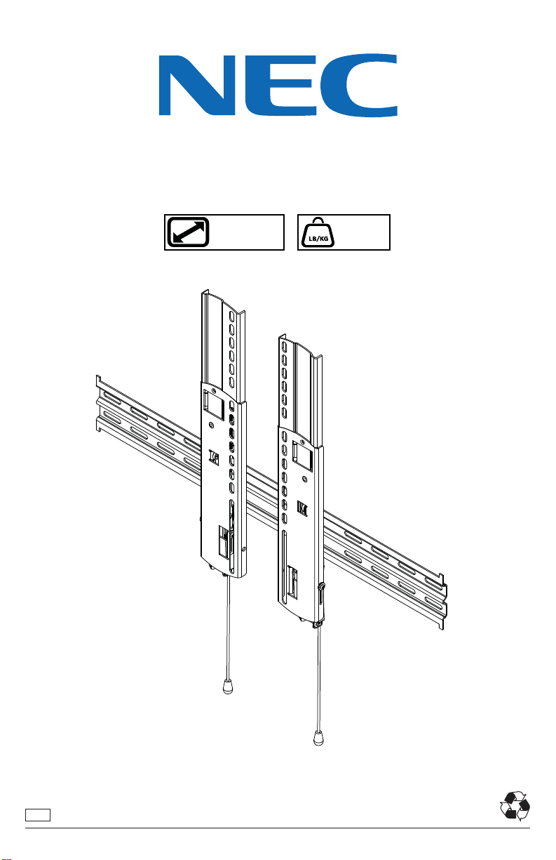
WMK-3255S
2
2014-01-08 #:125-9484-6 (2017-04-06)
5mm
(3/16")
ENG - This product is designed to be installed on wood stud, solid concrete or cinder block walls. Hardware is
included for wood stud, solid concrete and cinder block installation. Before installing make sure the supporting
surface will support the combined load of the equipment and hardware. Screws must be tightly secured. Do
not overtighten screws or damage can occur and product may fail. Never exceed the Maximum Load Capacity.
Always use an assistant or mechanical lifting equipment to safely lift and position equipment. This product is
intended for indoor use only. Use of this product outdoors could lead to product failure or personal injury. Be
careful not to pinch fi ngers when operating the mount. For support please call customer care at 1-800-865-2112.
WARNING
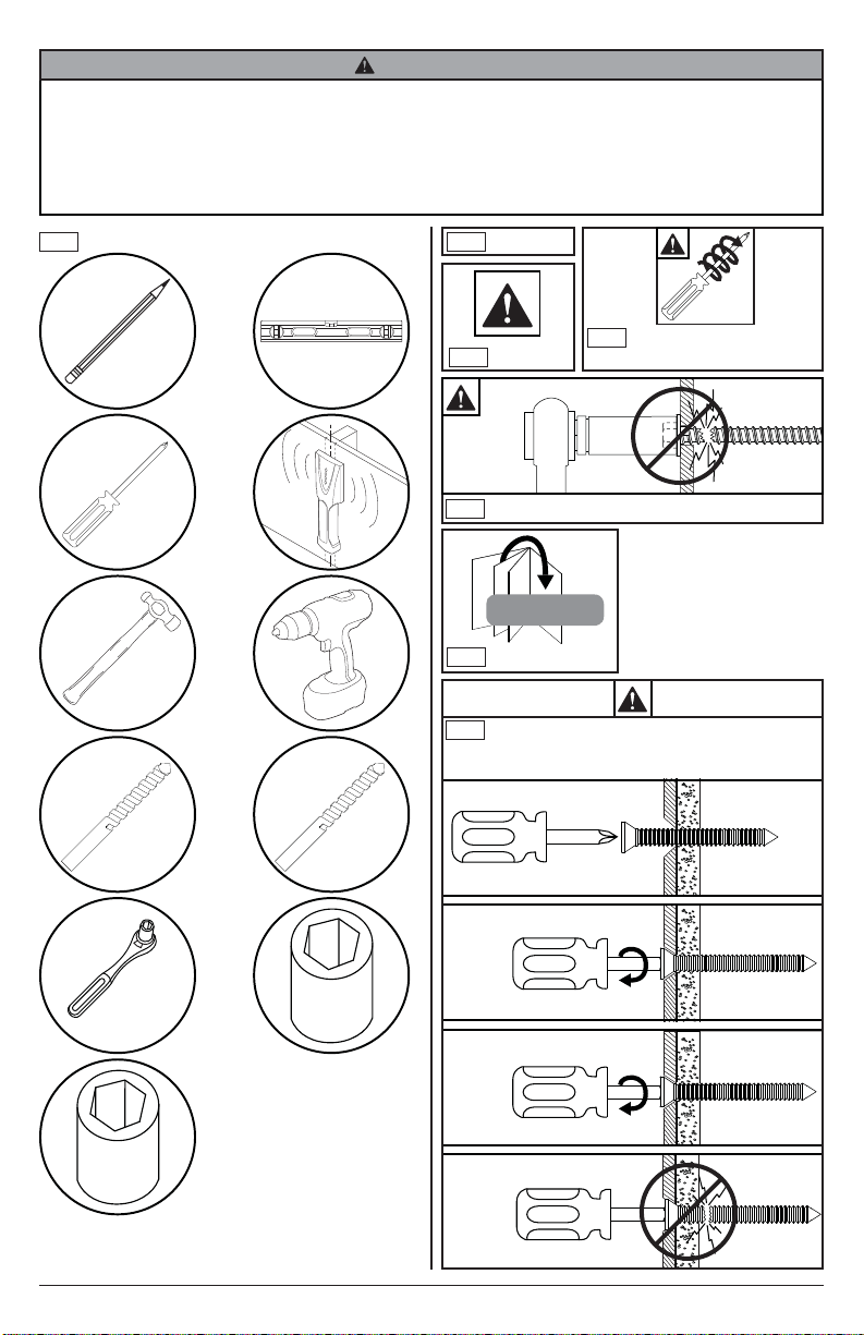
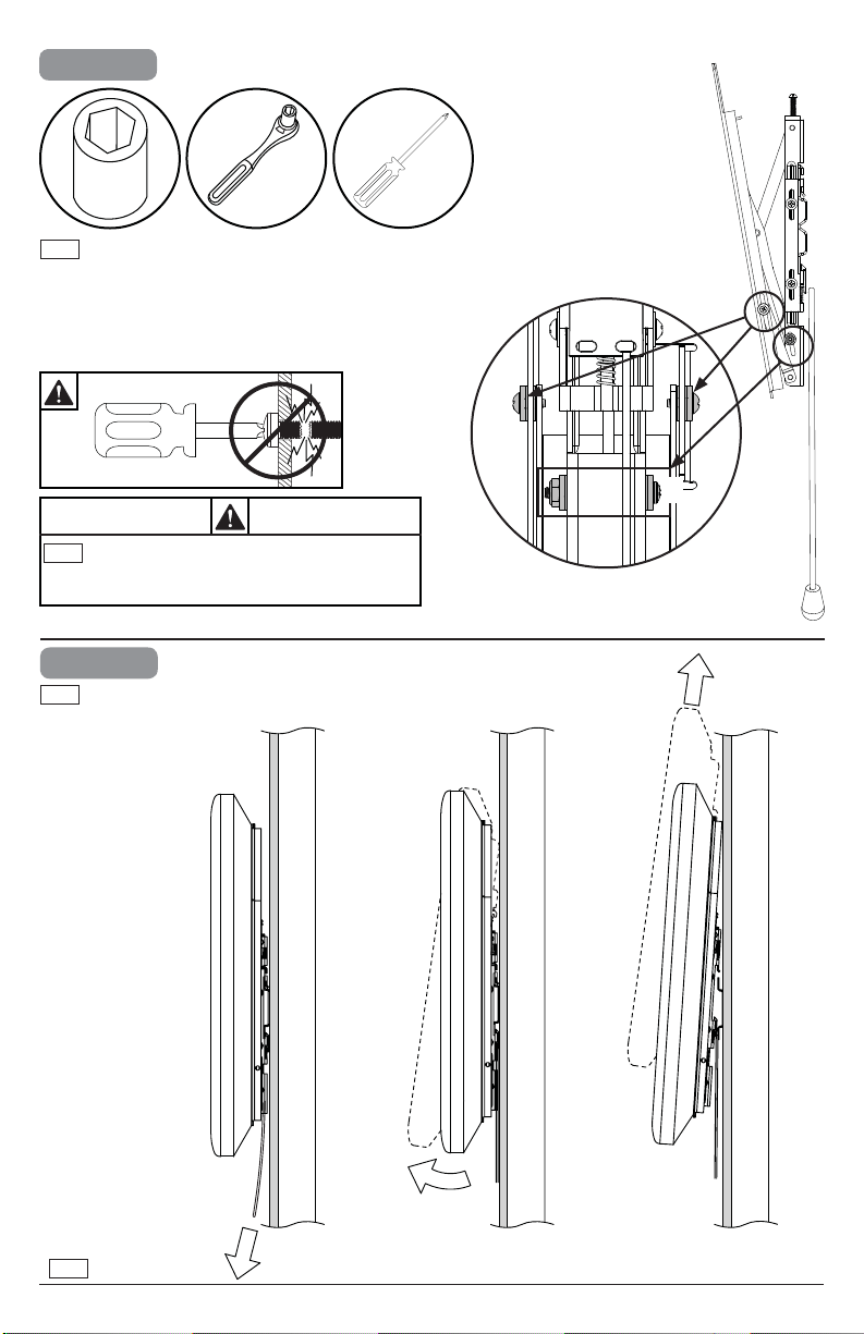
Tools Needed for Assembly.
ENG
1
2
ENG
To properly tighten screws: Tighten until screw
head makes contact, then tighten another 1/2
turn. Do not overtighten screws.
+1/2
4
3
5/32"
(4mm)
5/16"
(8mm)
3/8"
(10mm)
Symbols
ENG
WARNING
ENG
#
Skip to step.
ENG
x3
Screws must get at least
three full turns and fi t snug.
ENG
Do not overtighten screws.
ENG
3
2014-01-08 #:125-9484-6 (2017-04-06)
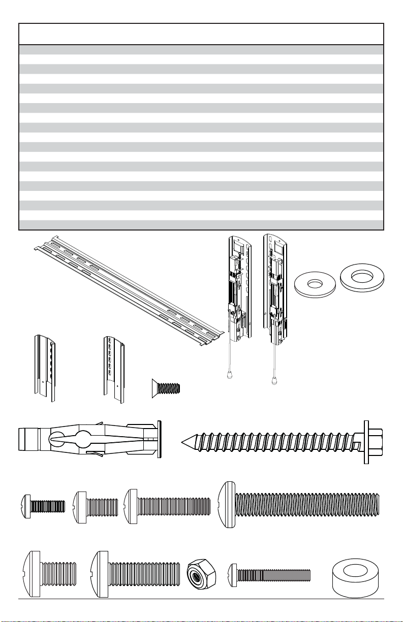
F (1)
right extension plate
G (1)
left extension plate
C (1)
left adapter
bracket
right adapter
bracket
B (1)
A (1)
wall plate
D
(
2
)
concrete anchor
E
(
2
)
#14 x 2-1/2" wood screw
I (4)
M6 x 12 mm
M8 x 12 mm
K (4)
M8 x 25 mm
M4 x 25mm
L (4)
O (4)
N (2)
nut
M (2)
fl at head screw
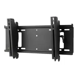
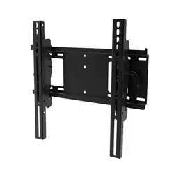
Parts List
Part #Description Qty
A wall plate 1 202-1008
B left adapter bracket 1 202-1621
C right adapter bracket 1 202-1622
D concrete anchor 2 590-0320
E #14 wood screw 2 5S1-015-C03
F left extension plate 1 202-1016
G right extension plate 1 202-1017
H M4 x 12 mm phillips screw 4 504-9013
I M6 x 12 mm phillips screw 4 520-1128
J M6 x 25 mm phillips screw 4 520-1208
K M8 x 12mm phillips screw 4 520-9571
L M8 x 25 mm phillips screw 4 520-1031
M 6-32" fl at head screw 2 520-1793
N 6-32" nylock nut 2 530-1006
O M4 x 25mm phillips screw 4 504-1015
P spacer 8 600-1215
R 5/16" washer 8 540-9406
S #10 washer (not used) 4 540-9400
T M8 x 50mm 4 521-1009
P (8)
spacer
H (4)
M4 x 12mm
J (4)
M6 x 25 mm
R (8)
5/16" washer
S (4)
#10 washer
(not used)
T
(
4
)
M8 x 50mm
4
2014-01-08 #:125-9484-6 (2017-04-06)
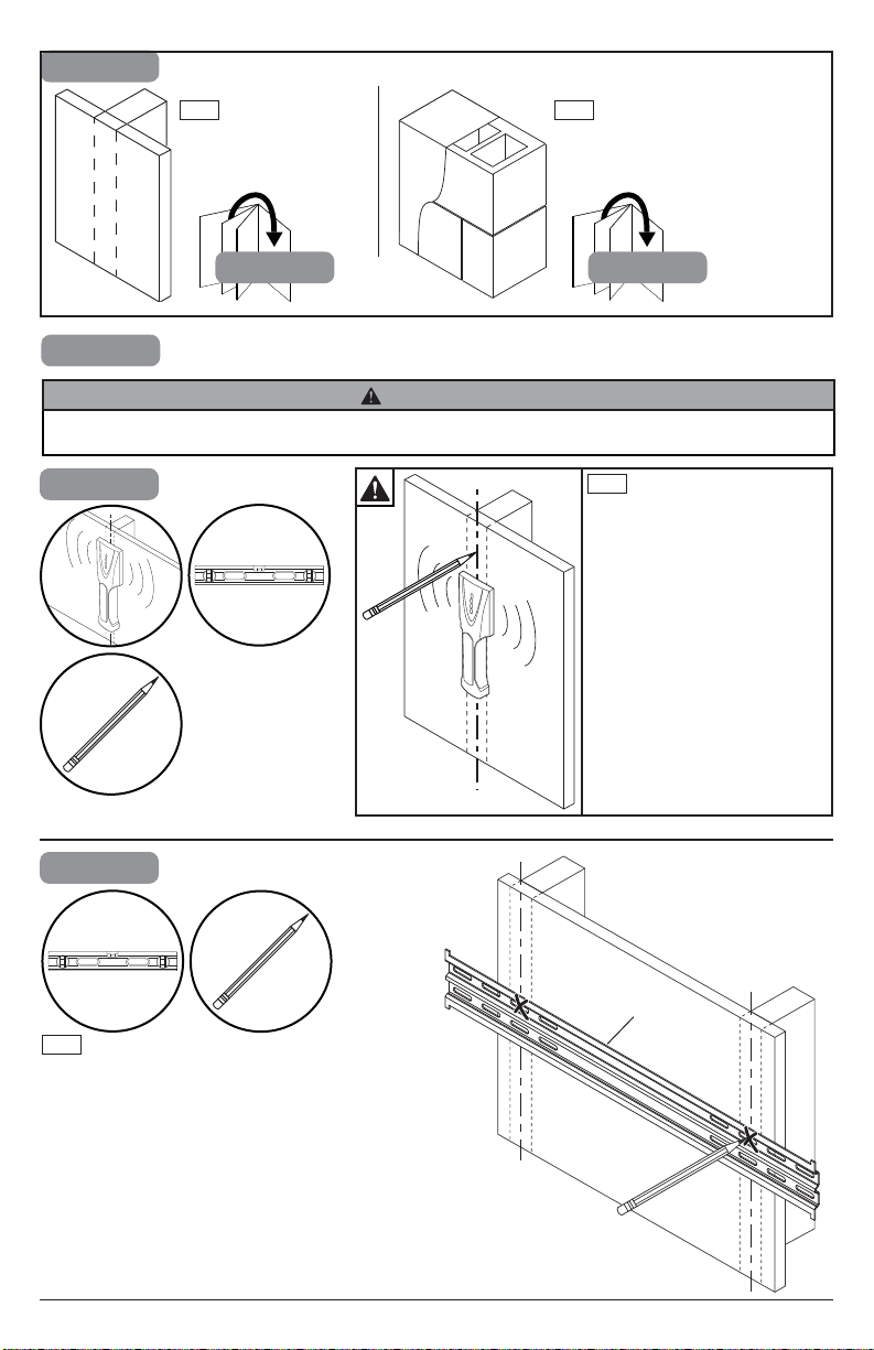
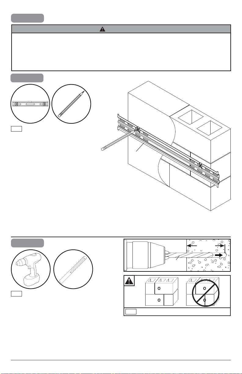
1a-1
Use stud fi nder to locate and
mark stud center lines.
ENG
1
1b1a
Wood stud wall
ENG
Concrete/Cinder block
ENG
1a
1a-2
Level wallplate. Mark mounting holes on stud
center lines.
ENG
A
ENG - When installing Peerless wall mounts on a wood stud wall covered with gypsum board (drywall), verify that
the wood studs are a minimum of 2" x 4" nominal size. Do not install over gypsum board thicker than 5/8".
WARNING
5
2014-01-08 #:125-9484-6 (2017-04-06)
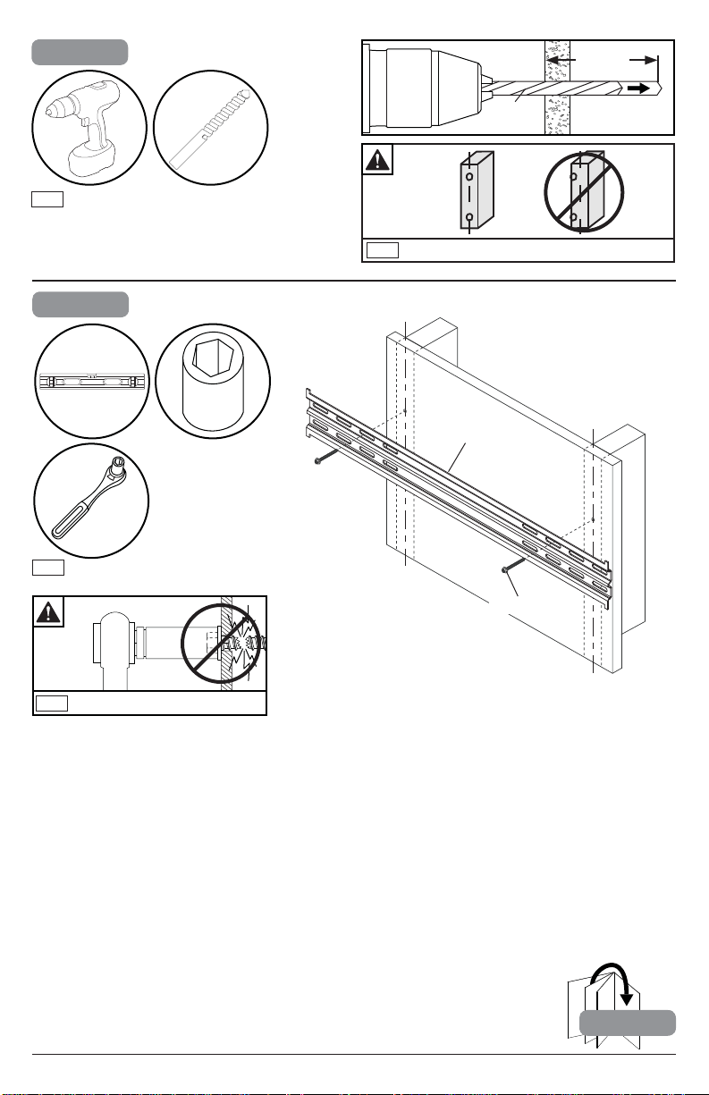
1a-3
Mounting hole must center on stud.
ENG
5/32"
(4mm)
Drill mounting holes into supporting surface
(2.5" (64 mm) minimum depth required).
ENG
2.5"
(64mm)
5/32"
(4mm)
1a-4
2
Level wallplate. Install using wood screws
provided.
ENG
E (2)
A
3/8"
(10mm)
Maximum 80 in. • lb (9 N.M.).
ENG
6
2014-01-08 #:125-9484-6 (2017-04-06)
1b
1b-1
Level wallplate. Mark mounting holes.
ENG
2.5"
(64mm)
5/16"
(8mm)
1b-2
5/16"
(8mm)
Do not drill into mortar joints.
ENG
Drill mounting holes into supporting surface
(2.5" (64 mm) minimum depth required).
ENG
A
ENG - When installing Peerless wall mounts on a concrete wall, the wall must be at least 8" thick with a minimum
compressive strength of 2000 psi. When installing Peerless wall mounts on a cinder block wall, the cinder blocks
must meet ASTM C-90 specifi cations and have a minimum nominal width of 8". Do not drill into mortar joints!
Be sure to mount in a solid part of the block, generally 1" (25 mm) minimum from the side of the block. It is
suggested that a standard electric drill on slow setting is used to drill the hole instead of a hammer drill to avoid
breaking out the back of the hole when entering a void or cavity. Never attach concrete expansion anchors to
concrete or cinder block covered with plaster, drywall or other fi nishing material.
WARNING
7
2014-01-08 #:125-9484-6 (2017-04-06)
D (2)
ENG
E (2)
1b-3
D
Insert anchor fl ush to concrete.
ENG
1b-4
Level wallplate. Install using concrete
anchors and wood screws provided.
3/8"
(10mm)
Maximum 80 in. • lb (9 N.M.).
ENG
8
2014-01-08 #:125-9484-6 (2017-04-06)
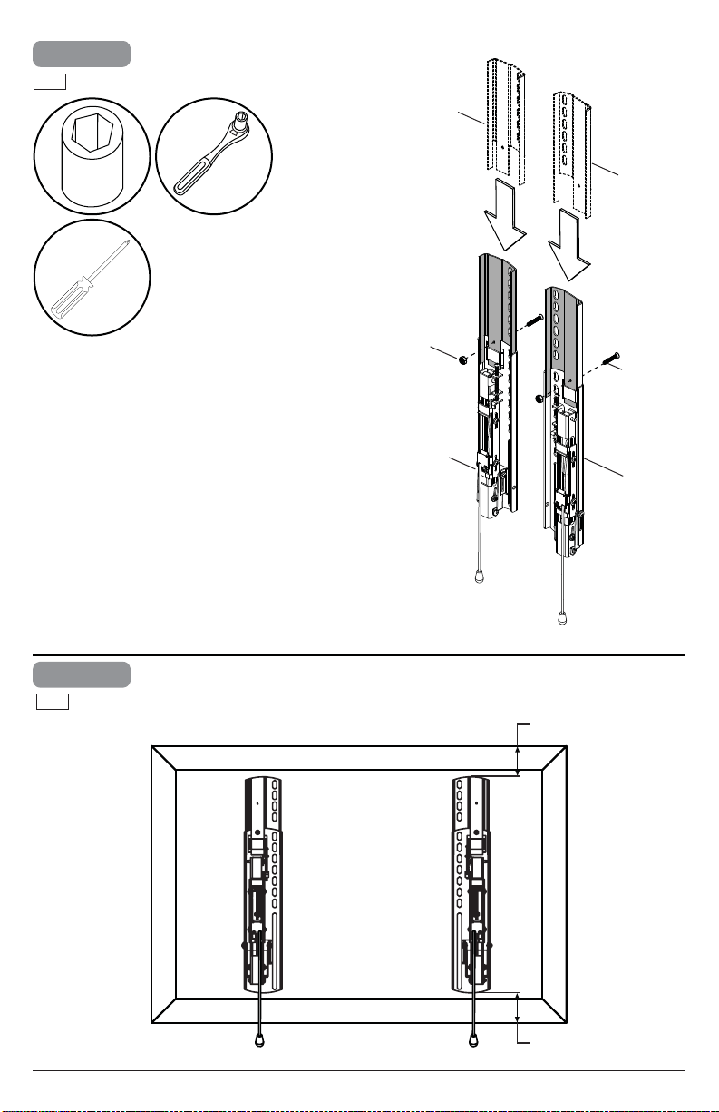
C
X
X
B
See compatibility on page 9.
ENG
OPTIONAL.
5mm
(3/16")
N (2)
B
F
G
C
O (2)
3
2
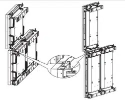
Center adapter brackets vertically on back of screen.
ENG
9
2014-01-08 #:125-9484-6 (2017-04-06)
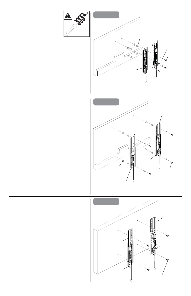
DISPLAY
4b
4a
4c
Note: Tilt may not be fully
supported for all displays
x3
B
C
G
F
G
F
P (8)
P (8)
I,J,K,L or T (4)
J (4)
J (4)
R (4)
R (4)
OPTIONAL
OPTIONAL
B
C
B
C
NEC E324
NEC E424, NEC E464, NEC E554
NEC P403, NEC P463, NEC P553, NEC V423,
NEC V552, NEC X401S, NEC X462S,
NEC X552S, NEC V463, NEC E655,
NEC P703, NEC V652, NEC X651UHD
10
2014-01-08 #:125-9484-6 (2017-04-06)
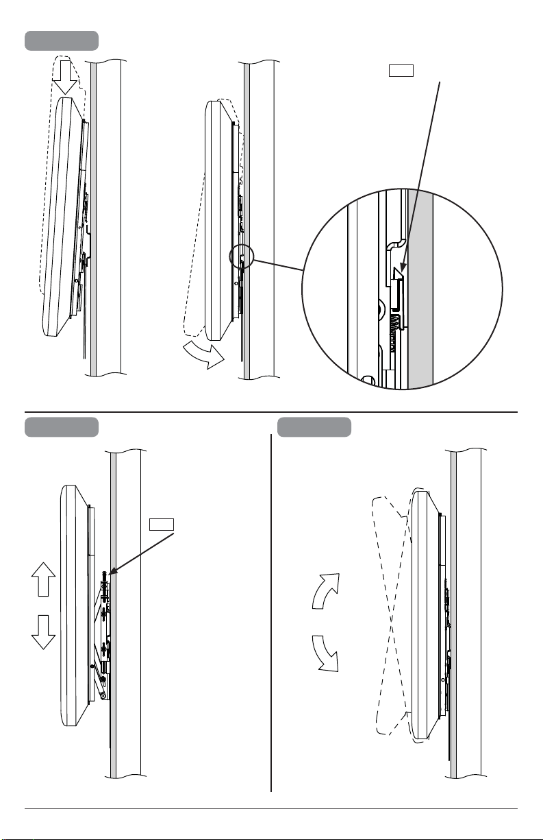
5
6
10°
ENG
Lock/unlock latch
7
Loosen, tighten.
ENG
+/-
11
2014-01-08 #:125-9484-6 (2017-04-06)
8
ENG
OPTIONAL
To increase tension and maintain degree of tilt,
tighten screw (x) on each adapter bracket. If more
tension is needed, tighten screws (y) on each
adapter bracket.
3/8"
(10mm)
y
x
y
Do not remove screw or loosen screw until it is
no longer engaged with the mount. Doing so may
cause the display to fall.
ENG
9
ENG
Removing display.
ENG
Lock/unlock latch
Note: Tilt may not be fully supported
for all displays

Peerless-AV Europe
Unit 3 Watford Interchange,
Colonial Way, Watford, Herts,
WD24 4WP, United Kingdom
Customer Care
44 (0) 1923 200 100
www.peerless-av.com
© 2017, Peerless Industries, Inc.
Peerless-AV de Mexico
Ave de las Industrias 413
Parque Industrial Escobedo
Escobedo N.L Mexico 66050
Servicio al Cliente
01-800-849-65-77
www.peerless-av.com
© 2017, Peerless Industries, Inc.
Peerless-AV
2300 White Oak Circle
Aurora, IL 60502
Email: [email protected]
Ph: (800) 865-2112
Fax: (800) 359-6500
www.peerless-av.com
© 2017, Peerless Industries, Inc.
Peerless Industries, Inc. (“Peerless”) warrants to original end-users of Peerless
®
products will be free from defects in material and
workmanship, under normal use, for a period of fi ve years from the date of purchase by the original end-user (but in no case longer than
six years after the date of the product's manufacture). At its option, Peerless will repair or replace, or refund the purchase price of, any
product which fails to conform with this warranty.
In no event shall the duration of any implied warranty of merchantability or fi tness for a particular purpose be longer than the
period of the applicable express warranty set forth above. Some states do not allow limitations on how long a implied warranty lasts,
so the above limitation may not apply to you.
This warranty does not cover damage caused by (a) service or repairs by the customer or a person who is not authorized for such service
or repairs by Peerless, (b) the failure to utilize proper packing when returning the product, (c) incorrect installation or the failure to follow
Peerless' instructions or warnings when installing, using or storing the product, or (d) misuse or accident, in transit or otherwise, including
in cases of third party actions and force majeure.
In no event shall Peerless be liable for incidental or consequential damages or damages arising from the theft of any product,
whether or not secured by a security device which may be included with the Peerless
®
product. Some states do not allow the
exclusion or limitation of incidental or consequential damages, so the above limitation or exclusion may not apply to you.
This warranty is in lieu of all other warranties, expressed or implied, and is the sole remedy with respect to product defects. No dealer,
distributor, installer or other person is authorized to modify or extend this Limited Warranty or impose any obligation on Peerless in
connection with the sale of any Peerless
®
product.
This warranty gives specifi c legal rights, and you may also have other rights which vary from state to state.
LIMITED FIVE-YEAR WARRANTY