General Controller LS143
INTRODUCTION WIRING PLAN - Free Mode
LifeSmart’s General Controller is a professional engineer device. It
integrate digital input and output from 3rd party devices. By connect-
ing to the General Controller, switches / buttons / sensors of dry contact
could integrate with LifeSmart system perfectly and achieve intelligent
control.
Copyright © 2020 LifeSmart Inc. All Rights Reserved.
Facebook: ilifesmarthome
Twitter: ilifesmarthome
SPECIFICATIONS
Size
Weight
Material
Wireless protocol
Wireless distance
Operating temperature
Operating humidity
Input
Maximum load
Static consumption
83.6*47.0*22.3mm
50g
ABS
CoSS
200m (Open field)
-5 ~ 45°C
5~ 90%
DC 12V/24V
3A
<1.5W
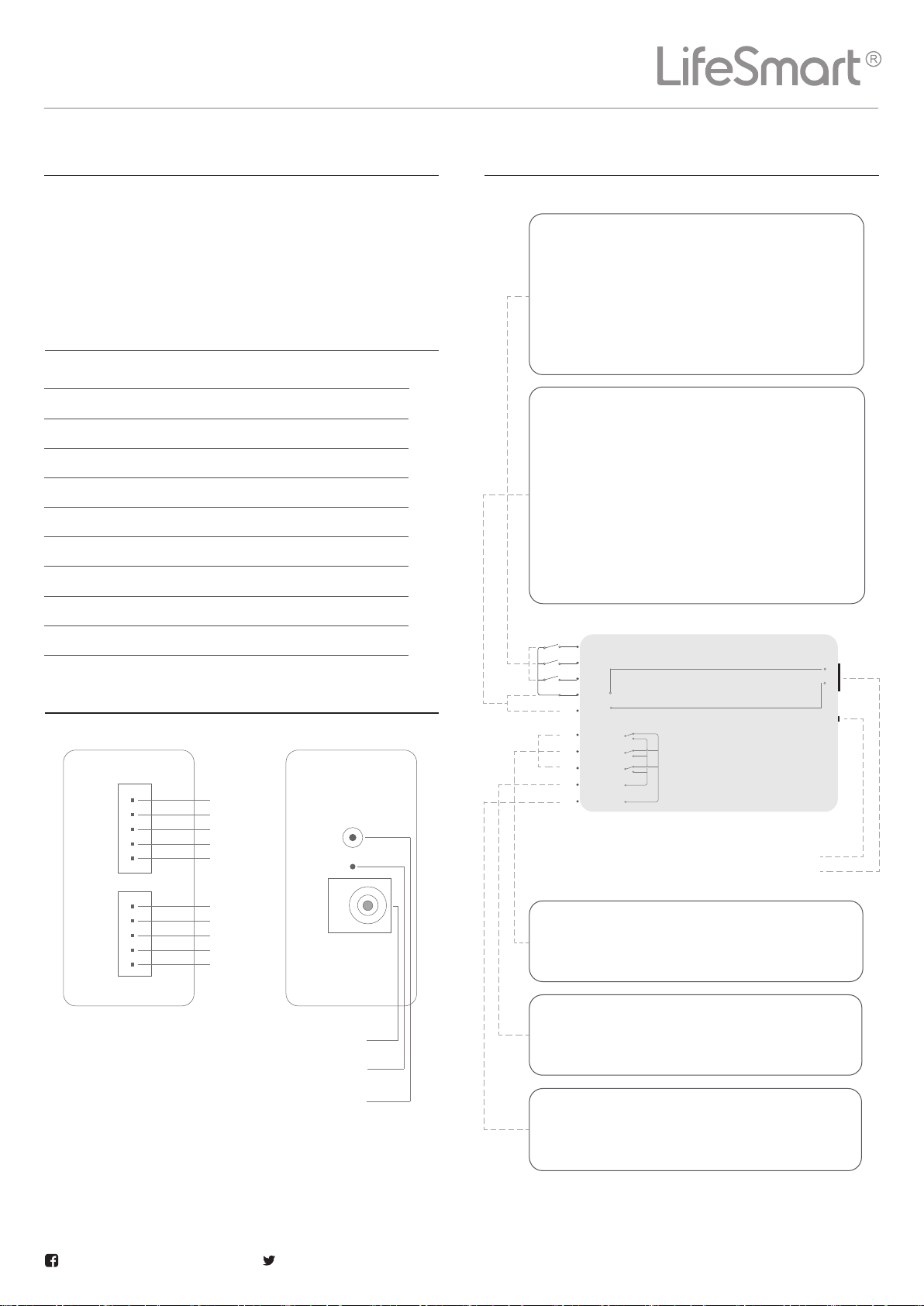
ILLUSTRATION
It can be connected to the dry contact of differ-
ent sensors (like smoke sensor, gas sensor and
so on ) using wired connection. When there is a
signal detected, which also means K1/K2/K3 is
connected with GND, App uploads data and then
a notification will be pushed or trigger will be
activated accordingly.
GND/DC+ ports are connected in parallel with the
power resource interface of the general control-
ler. If the voltage of the device and the general
controller match, these ports can be used to
power the device by connecting the device's
power terminals (GND/0V and 12V/24V), or if
the device has its own power resource, it can
also be connected here to power the general
controller, so that the general controller does
not need an external power supply.
It can connect to three different output interfac-
es here. The control channels with CH1, CH2 and
CH3 can work independently.
COM+ is normally open, and disconnected with
CH1, CH2 and CH3 in default. If the control item
is on then it is connected.
COM- is normally closed, and connected with
CH1, CH2 and CH3 in default. If the control item
is on then it is disconnected.
K1
K2
K3
CND
DC+
CH1
CH2
CH3
COM+
COM-
Universal Control Board
Power Resource Interface
Configuration Button
Indicator light
Power resource interface
K1
K2
K3
CND
DC+
CH1
CH2
CH3
COM+
COM-
Configuration button
Notice: General Controller installation may involves strong
current operation, please contact electrician to operate!
Notice: General Controller has several working mode,
please follow the wiring plan.
General Controller LS143
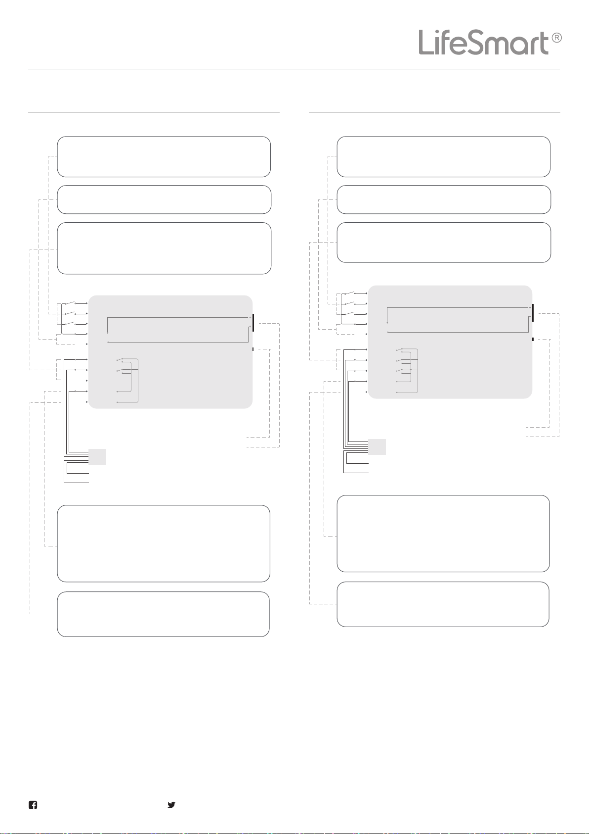
WIRING PLAN - Two-way Curtain Control WIRING PLAN - Three-way Curtain Control
Copyright © 2020 LifeSmart Inc. All Rights Reserved.
Facebook: ilifesmarthome
Twitter: ilifesmarthome
The on/off status of CH1, CH2 and CH3 depends
on the connection of K1/K2/K3.
Connected to the power resource parallel.
CH1 and CH2 is connected to on and off dry contact
of curtain motor, while CH3 is not connected to any
interface.
COM+ is normally open, and connected to the
public interface of the motor, and is disconnect-
ed with CH1, CH2 and CH3 in default. If the control
item is on then it is connected. It can be powered
by GND.
COM- is normally closed and not connected to
any interface. It can be powered by DC+.
K1
K2
K3
CND
DC+
CH1
CH2
CH3
COM+
COM-
Universal Control Board
Curtain Motor
Interface
Power Resource Interface
ON
OFF
ON
OFF
STOP
PUBLIC
Live line
Neutral line
Configuration Button
The on/off status of CH1, CH2 and CH3 depends
on the connection of K1/K2/K3.
Connected to the power resource parallel.
CH1, CH2 and CH3 is connected to on, off and stop
dry contact of curtain motor.
COM+ is normally open, and connected to the
public interface of the motor, and is disconnect-
ed with CH1, CH2 and CH3 in default. If the control
item is on then it is connected. It can be powered
by GND.
COM- is normally closed and not connected to
any interface. It can be powered by DC+.
K1
K2
K3
CND
DC+
CH1
CH2
CH3
COM+
COM-
Universal Control Board
Curtain Motor
Interface
Power Resource Interface
ON
OFF
ON
OFF
STOP
STOP
PUBLIC
Live line
Neutral line
Configuration Button
General Controller LS143
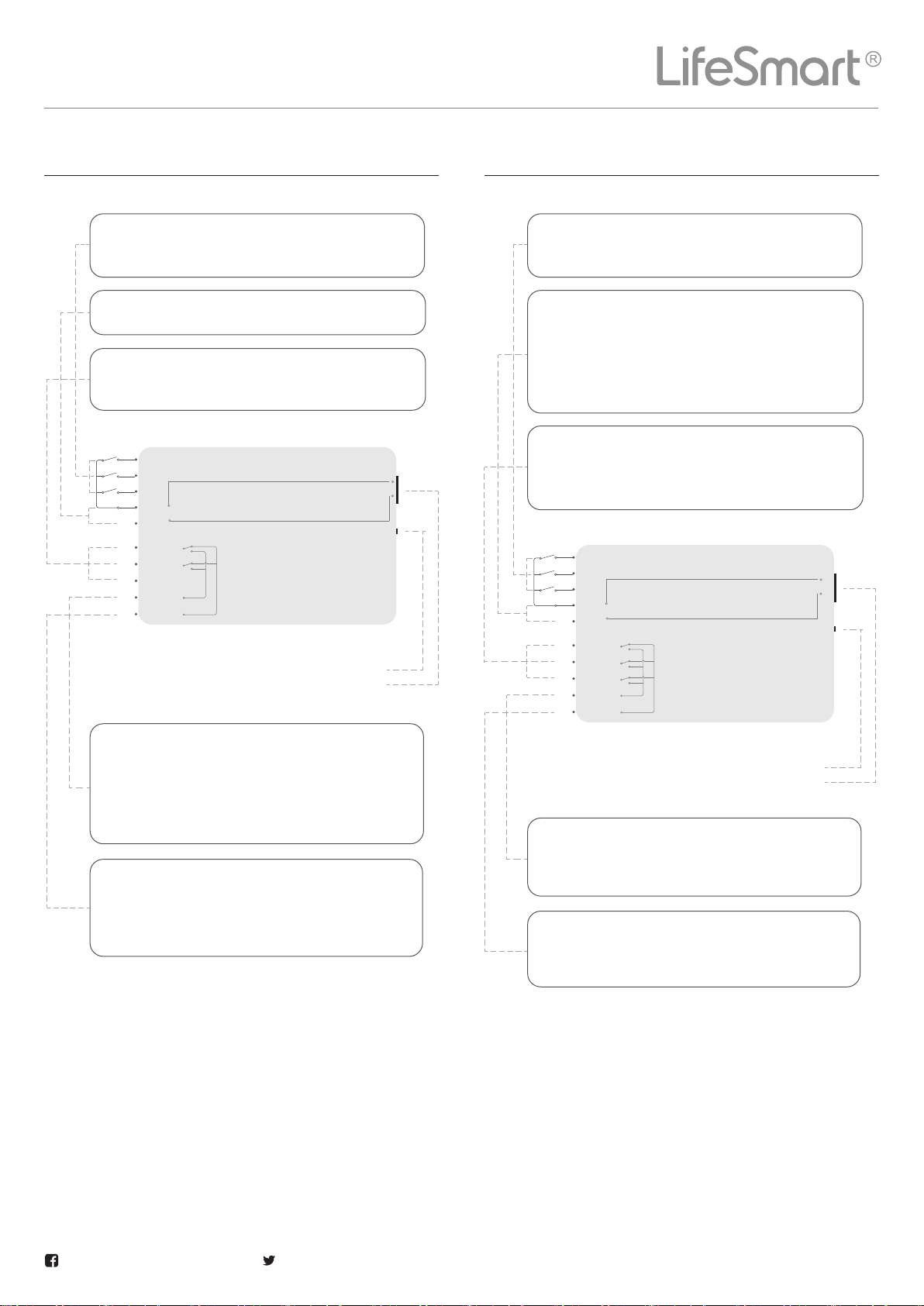
WIRING PLAN - DC Motor WIRING PLAN - Three-way Switch
Copyright © 2020 LifeSmart Inc. All Rights Reserved.
Facebook: ilifesmarthome
Twitter: ilifesmarthome
The on/off status of CH1, CH2 and CH3 depends
on the connection of K1/K2/K3.
Connected to the power resource parallel.
CH1 and CH2 is connected to each interface of the DC
motor separately.
COM+ is normally open, and connected to the
public interface of the motor, and is disconnect-
ed with CH1, CH2 and CH3 in default. If the control
item is on then it is connected. It can be powered
by GND.
COM- is normally closed and connected with
CH1 and CH2 in default. If the control item is on
then it is disconnected.. It can be powered by
DC+.
K1
K2
K3
CND
DC+
CH1
CH2
CH3
COM+
COM-
Universal Control Board
Power Resource Interface
Configuration Button
The on/off status of CH1, CH2 and CH3 depends
on the connection of K1/K2/K3.
1. Connected to the power resource parallel.
2. Power the sensor using GND/0V and 12V/24V.
3. If the sensor has a power resource itself, the
sensor also can power the Universal Control Board
using the DC input.
It can connect to three different output interfaces here.
The control channels with CH1, CH2 and CH3 can work
independently.
COM+ is normally open, and disconnected with
CH1, CH2 and CH3 in default. If the control item
is on then it is connected.
COM- is normally closed, and connected with
CH1,CH2 and CH3 in default. If the control item
is on then it is disconnected.
K1
K2
K3
CND
DC+
CH1
CH2
CH3
COM+
COM-
Universal Control Board
Power Resource Interface
Configuration Button
LifeSmart’s General Controller needs to be paired with Smart Station
to join the smart system.
1 After configuration of the smart station, click “+” on the app home page,
then click “ Add Device ”, select “ General Controller ”, enter pairing
mode.
2 Follow the instruction on the app to finish pairing.
3 If a time-out error occurs, please repeat step 1-3.
4 Select the correct working mode in the settings according to wiring
plan.
SET UP
User support e-mail address
Website
www.ilifesmart.com
Thank you for purchasing this LifeSmart product. In order to protect your
rights, please read the following content carefully: The warranty period of
our company's products is one year from the date of purchase or longer if
local laws impose a longer minimum term, in which case the minimum
term is the warranty period. During the warranty period, any faults caused
by the product itself or for quality problems that arise under normal
usage, LifeSmart will provide a free replacement.
WARRANTY DESCRIPTION
LifeSmart is a trademark of Hangzhou LifeSmart Technology Co., Ltd. As for
the trademarks, product logos and product names from other companies
presented within this manual, they are possessed by their own right
holders. Without our written permission, no entity or individual shall
extract, copy or disseminate in part or the whole of themanual contents in
any form. Due to product version upgrades or other reasons, content of this
manual may change. Our company reserves the right to change the
contents of this manual without any notice. This manual is used only for
instructional purposes. We strive to provide accurate information in this
manual, but we are not able to ensure that the content of this manual is
current. Statements, information and advice in this manual do not
constitute any expressed or implied assurance. Updated manuals are
available on our website at www.ilifesmart.com or by contacting our team.
DECLARATION
The following conditions are not covered by the warranty:
Product failure or damage caused by installation, use, and mainte-
nance that is not in accordance with the product instructions;
Products beyond the warranty period;
Products that have the barcode tampered with or removed;
Devices that have been tampered with or customized outside of Life-
Smart Terms Of Service as on the LifeSmart App and website;
User-caused damage, such as inappropriate voltage input, high tem-
perature, accidental spillage, physical damage, etc;
Product failure or damage caused by force majeure such as earth-
quakes, fires, or floods;
Product failure or damage caused by other problems except the pro-
duct itself.
ATTENTION
General Controller LS143
Copyright © 2020 LifeSmart Inc. All Rights Reserved.
Facebook: ilifesmarthome
Twitter: ilifesmarthome
CERTIFICATION
Quality inspector
QC
PASS
Notice: This device may be used in each member state in EU.
DECLARATION OF CONFORMITY
Hereby, LifeSmart declares that the radio equipment type is in compliance
with Directive 2014/53/EU. The full text of the EU declaration of conformity
is available at the following internet address:
http://global.ilifesmart.com/ce/docs/