SP-404MK2 (Version 3.00)
Reference Manual

Table of contents
2
Table of contents
Introduction .............................................................................. 4
What You Should Know About This Unit (How Data is
Organized) ............................................................................. 4
What’s a Sample? ............................................................................. 4
What’s a Pattern? ............................................................................. 4
Banks and Projects .......................................................................... 5
Getting Things Ready ........................................................... 6
Connecting External Equipment ................................................ 6
About the Power Supply ............................................................... 8
Turning the Power On/Off ......................................................... 10
Playing Back Samples (SAMPLE MODE) ........................ 12
Selecting a Sample Bank ..................................................... 12
Adjusting the Volume for All Banks (BANK VOLUME) ....... 13
Playing Back a Sample to the Tempo of a Song (BPM SYNC)
.............................................................................................. 14
Playing Back Only While a Pad is Pressed (GATE) ............. 15
Playing Back Samples Only One Time (One-shot Playback)
.............................................................................................. 16
Playing Back Samples Repeatedly (LOOP) ........................ 17
Playing Back a Sample in Reverse (REVERSE) .................... 18
Playing Back Samples in Detailed Steps (ROLL) ................ 19
Setting the Roll Interval .............................................................. 19
Setting a Fixed Sample Volume (FIXED VELOCITY) .......... 21
Changing the Sample Volume for Playback (16 VELOCITY)
.............................................................................................. 22
Playing Back Samples in Scale Pitches (CHROMATIC) ...... 23
Muting the Playback of a Sample (PAD MUTE) ................. 24
Playing Back Multiple Pads at the Same Time (PAD LINK
GROUPS) .............................................................................. 25
Preventing Samples from Playing Back at the Same Time
(MUTE GROUP) .................................................................... 26
Stopping All Sample Playback (STOP) ............................... 27
Pausing the Sound of a Sample (PAUSE) .............................. 27
Disabling Buttons that Are Not Used When Playing Live
(LIVE MODE) ......................................................................... 28
Using the Effects ................................................................... 29
Adding Effects to a Sample (BUS FX) ................................. 29
Assigning Effects to BUS 1 and BUS 2 .................................... 30
Deciding on Effects to Use for Each Sample ........................ 30
Using the MFX Effects .................................................................. 31
Editing the Effects ............................................................... 33
Turning Effects On/Off at the Desired Timing ................... 34
Temporarily Output Only the Effect Sound (MUTE BUS) .. 35
Sampling (SAMPLING) ........................................................ 37
Configuring the Sampling Settings (RECORD SETTING) ... 37
Configuring the Input Effects (INPUT FX) ............................. 37
Sampling .............................................................................. 39
Adding a Count-in Before Sampling ...................................... 39
Automatically Setting the End Point of a Sample (END
SNAP) ................................................................................................ 39
Resampling a Sample (RESAMPLE) .................................... 41
Sampling What You Previously Played (SKIP-BACK
SAMPLING) .......................................................................... 42
Editing a Sample (SAMPLE EDIT) ..................................... 44
Setting the Playback and Loop Regions (START/END) ..... 44
Processing a Sample .................................................................... 45
Marking and Splitting Samples (MARK) ............................ 46
Using a Marker to Split and Assign a Sample to a Pad
(CHOP) ............................................................................................... 48
Making Fade-in/Fade-out Settings (ENVELOPE) ............... 49
Changing the Pitch or Playback Speed of a Sample
(PITCH/SPEED) ..................................................................... 52
Displaying Parameters Set in a Sample ............................. 54
Initializing the Sample Parameters (INIT PARAM) ............ 55
Organizing the Samples ..................................................... 56
Exchanging (Swapping) Samples Between Pads ................ 56
Copying the Sample from a Pad ............................................... 56
Copying all samples in a bank to another bank .................. 57
Protecting a Sample (PROTECT) ............................................... 57
Deleting the Sample from a Pad .............................................. 57
Combining Samples to Create a Pattern (PATTERN
SEQUENCER) .......................................................................... 59
Playing a Pattern ................................................................. 59
Creating a New Pattern (Real-time Recording) ................. 60
Adding a Count-in Before Recording a Pattern ................... 61
Creating a New Pattern (TR-REC) ....................................... 62
Converting Patterns to Samples ........................................ 65
Sampling a Pattern (RESAMPLE) ............................................... 65
Converting Patterns to Samples (BOUNCE) .......................... 66
Selecting a Pattern Bank .................................................... 67
Playing Back Patterns in Order (PATTERN CHAIN) ........... 68
Recording Effect Operations to a Pattern (EFX MOTION
REC) ...................................................................................... 71
Deleting Effect Operations Recorded in a Pattern (EFX
MOTION ERASE) .................................................................. 72
Deleting Specific Effect Operations From a Pattern .......... 72
Recording Pad Mute Operations to a Pattern (PAD MUTE
MOTION REC) ....................................................................... 73
Deleting Pad Mute Operations Recorded in a Pattern (PAD
MUTE MOTION ERASE) ........................................................ 74
Deleting Specific Pad Mute Operations from a Pattern ... 74
Editing a Pattern (PATTERN EDIT) ...................................... 75
Copying and Connecting Patterns (DUPLICATE) ................ 75
Cropping Unnecessary Sections from a Pattern (CROP) .. 75
Aligning the Playback Timing of Samples Inputted to a
Pattern (QUANTIZE) ...................................................................... 76
Organizing the Pattern Data .............................................. 78
Exchanging (Swapping) Patterns Between Pads ................ 78
Copying the Pattern of a Pad .................................................... 78
Extracting Specific Samples (Pads) from a Pattern............. 79
Copying all patterns in a bank to another bank ................. 79
Protecting a Pattern (PROTECT) ................................................ 80
Deleting the Pattern from a Pad ............................................... 80
Setting the Tempo ............................................................... 82
Setting the Tempo Data in a Sample ................................. 83
Setting the Tempo for a Bank or Project ........................... 85
Setting the Tempo in Time with the Rhythm (Tap Tempo)
.............................................................................................. 86
Mixing the Samples (DJ MODE) ....................................... 87
Playing Back Samples While in DJ Mode (PAD MODE) ..... 89
Playing Back Patterns While in DJ Mode ........................... 90
Playing Back a Sample from the Marker Position ............. 91
Adding a Marker While Playing Back a Sample ................ 92
Editing a Marker While Playing Back a Sample .................... 92

Table of contents
3
Deleting All Set Markers from a Sample ............................ 93
Editing a Sample in DJ Mode .............................................. 94
Monitoring with Headphones (CUE) .............................. 95
Inputting Sound from an Electronic Musical
Instrument, Mic or Guitar ................................................... 96
Inputting Audio from a Computer or Mobile Device
(USB AUDIO) ........................................................................... 97
Selecting a Project ............................................................... 98
Organizing Projects ............................................................. 99
Copying a Project ................................................................ 99
Deleting a Project .............................................................. 100
Customizing This Unit ....................................................... 101
Attaching/Removing the Faceplate of This Unit ............. 101
Customizing the Opening Screen .................................... 103
Preparing an Opening Image ................................................. 103
Saving an Opening Image to a Project ................................ 103
Customizing the Screen Saver .......................................... 104
Preparing a Screen Saver Image ............................................ 104
Enabling a Custom Screen Saver ........................................... 104
Saving the Screen Saver Image to a Project ...................... 105
Configuring the Various Settings (UTILITY) ............... 106
Editing the Settings Related to this Unit (System) .......... 106
Configuring the Pad-related Settings (PAD SETTING) .... 107
Configuring the Effect Settings (EFX SET) ....................... 108
Configuring the Effect Routing .............................................. 108
Adding Effects to the Overall Sound (BUS 3, BUS 4) ....... 109
Changing the Effects Assigned to BUS 3 and BUS 4 ....... 109
Editing the Effects for BUS 3 and BUS 4 ............................... 110
Assigning the Desired Effect to an Effect Button (DIRECT
FX) .................................................................................................... 111
Configuring the Input Effects (INPUT FX) ........................... 112
Sending the Audio Input from the INPUT Jack to a Bus 113
Importing/Exporting (Using the SD Card) ....................... 114
Importing Samples (IMPORT SAMPLE) ................................ 116
Exporting Samples (EXPORT SAMPLE) ................................. 117
Importing a Project (IMPORT PROJECT) .............................. 118
Exporting a Project (EXPORT PROJECT) ............................... 119
Backing up Your Data (BACKUP) ............................................ 120
Restoring from Backup Data (RESTORE) .............................. 120
Formatting an SD Card.............................................................. 121
Restoring the Factory Settings (FACTORY RESET) .......... 122
Appendix ............................................................................... 123
Parameter Guide ............................................................... 123
SYSTEM ........................................................................................... 123
PAD SET .......................................................................................... 126
EFX SET ........................................................................................... 127
MFX List .............................................................................. 129
Filter+Drive ................................................................................... 129
Resonator ...................................................................................... 129
Sync Delay ..................................................................................... 129
Isolator ........................................................................................... 129
DJFX Looper ................................................................................. 130
Scatter ............................................................................................ 130
Downer .......................................................................................... 130
Ha-Dou ........................................................................................... 130
Ko-Da-Ma ...................................................................................... 131
Zan-Zou ......................................................................................... 131
To-Gu-Ro ....................................................................................... 131
SBF ................................................................................................... 132
Stopper .......................................................................................... 132
Tape Echo ...................................................................................... 132
TimeCtrlDly ................................................................................... 132
Super Filter ................................................................................... 133
WrmSaturator .............................................................................. 133
303 VinylSim ................................................................................. 133
404 VinylSim ................................................................................. 133
Cassette Sim ................................................................................. 134
Lo-fi ................................................................................................. 134
Reverb ............................................................................................ 134
Chorus ............................................................................................ 134
JUNO Chorus ................................................................................ 134
Flanger ........................................................................................... 135
Phaser ............................................................................................. 135
Wah ................................................................................................. 135
Slicer................................................................................................ 136
Tremolo/Pan ................................................................................ 136
Chromatic PS ................................................................................ 136
Hyper-Reso ................................................................................... 136
Ring Mod ....................................................................................... 137
Crusher ........................................................................................... 137
Overdrive ....................................................................................... 137
Distortion ...................................................................................... 137
Equalizer ........................................................................................ 138
Compressor .................................................................................. 138
SX Reverb ...................................................................................... 138
SX Delay ......................................................................................... 138
Cloud Delay .................................................................................. 138
Back Spin ....................................................................................... 139
Auto Pitch ..................................................................................... 139
Vocoder .......................................................................................... 139
Harmony ........................................................................................ 140
Gt Amp Sim .................................................................................. 140
Control change messages and corresponding effects .. 140
List of Shortcut Keys ......................................................... 143
Shortcuts that use the [SHIFT] button ................................. 143
Shortcuts that use the [REMAIN] button ............................ 144
Shortcuts that use the [VALUE] button ............................... 144
Shortcuts that use the [DEL] button .................................... 145
Shortcuts that use the [COPY] button ................................. 145
Shortcuts that use the [MFX] button ................................... 145
Shortcuts used in DJ mode ..................................................... 145
Shortcuts used in TR-REC ......................................................... 146
Error Messages .................................................................. 147
Audio Diagram .................................................................. 148
Main Specifications ........................................................... 149
MIDI Implementation Chart ............................................. 150
MIDI Note Map ............................................................................ 152
Introduction
4
Introduction
The SP-404MK2 lets you do everything from audio sampling to editing, creating your own songs and performing... all in one unit.
This Reference Manual assumes that your unit is using software version 3.00 or later.
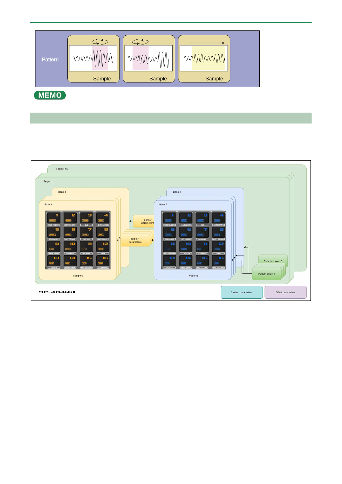
What You Should Know About This Unit (How Data is Organized)
The SP-404MK2 handles a large amount of data, including audio materials and data used to create songs. In this section, we
explain the role of each type of data and the structure used to manage data on the SP-404MK2.
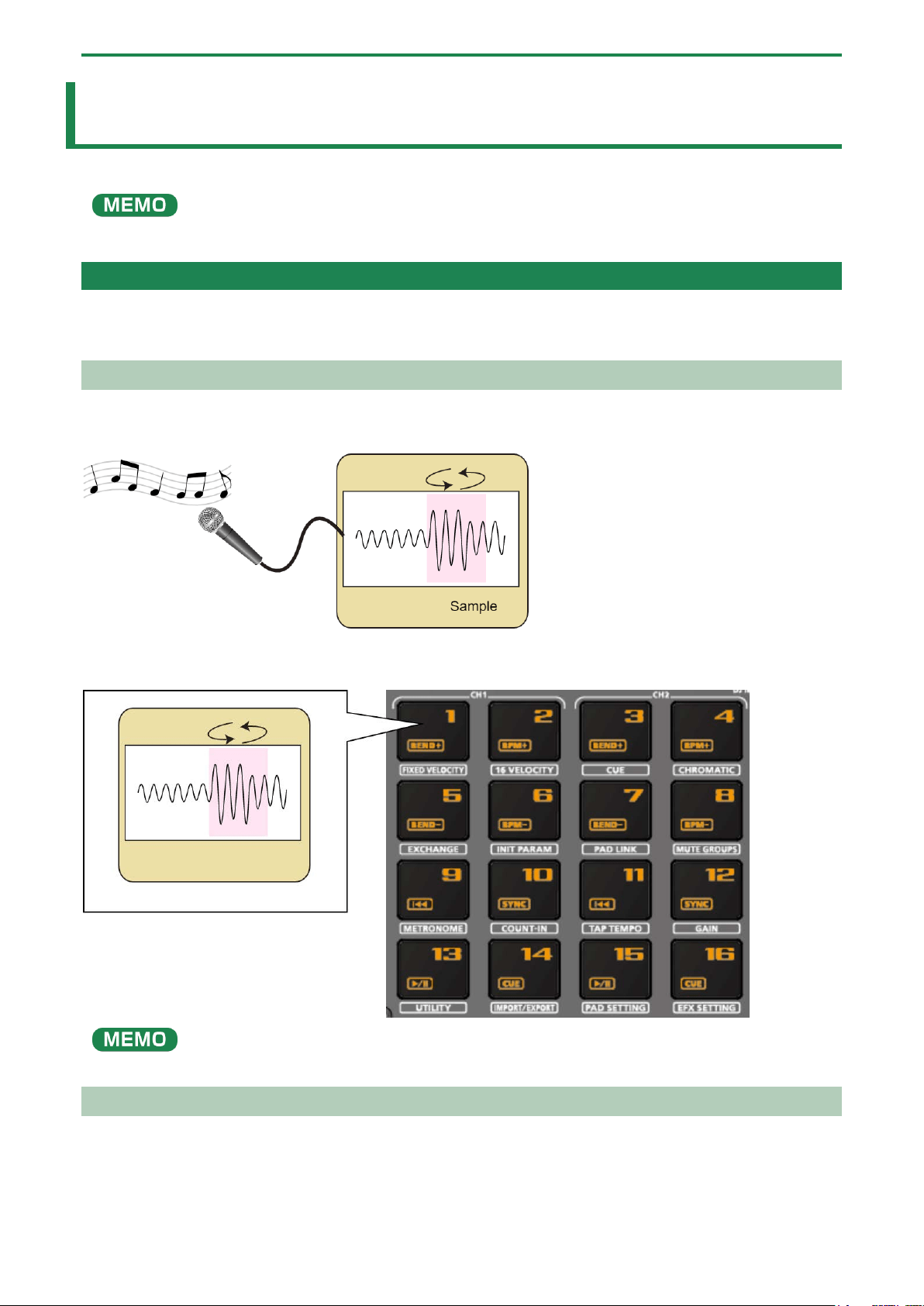
What’s a Sample?
A sample is a collection of audio that has been sampled (recorded audio data) and settings such as loop settings and routings to
BUS FX (effects).
Samples can be assigned to pads [1]–[16] and played back, or you can use them as parts of patterns to construct your song.
A collection of 16 samples is a called a “bank”, and you can store up to 10 banks (A–J).
What’s a Pattern?
A pattern is a set of data that contains the order in which the samples should be played back.
You can create a song by pressing the pads to play back several samples and then recording your performance as a pattern.
Use the pattern sequencer to record patterns.
Introduction
5
A collection of 16 patterns is a called a “bank”, and you can store up to 10 banks (A–J).
Banks and Projects
The 10 banks of samples and 10 banks of patterns are collectively managed as a “project”.
The SP-404MK2 can store 16 different projects.
Introduction
6
Getting Things Ready
Now, let’s get ready to use the SP-404MK2. This section explains how to prepare and connect to external equipment for
outputting sound, as well as the different ways to power this unit.
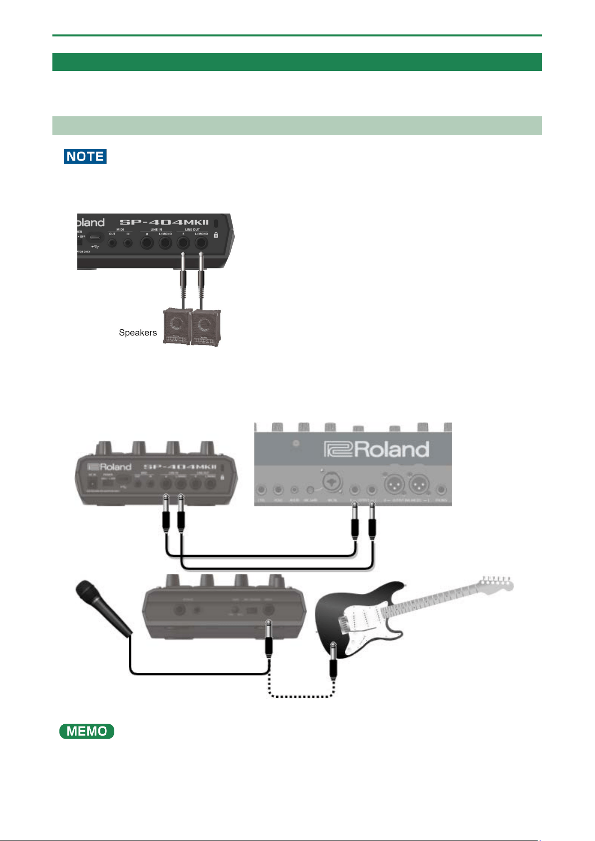
Connecting External Equipment
To prevent malfunction and equipment failure, always turn down the volume, and turn off all the units before making any
connections.
1.
Connect your amp or speakers to the LINE OUT jacks on the rear panel.
2.
Use the PHONES jack when connecting headphones or earphones.
Connect an electronic musical instrument (such as a synthesizer) to the LINE IN jack(s) on the rear panel.
3.
Connect your mic or guitar to the INPUT jack on the front panel.
You can change the input impedance of the INPUT jack on the front panel. When connecting a high-impedance instrument
(such as a guitar or bass guitar), flip the [MIC/GUITAR] switch to the right (towards the INPUT jack).

Introduction
7
Connecting to a Computer or Mobile Device
You can transmit and receive audio and MIDI data by connecting a USB cable from your computer or mobile device (smartphone
or tablet) to the SP-404MK2.
You don’t need to install a device driver on your computer or other device to do this (the SP-404MK2 supports USB Audio Device
Class 2.0 specs).
●
Connecting the SP-404MK2 to your computer or mobile device lets you transmit/receive audio output and MIDI data to
and from your computer or mobile device and the SP-404MK2.
● Note that data cannot be directly transmitted/received between the SP-404MK2 and your computer or mobile device if
you’re connecting through a USB hub.
● Do not use a USB cable that is designed only for charging a device. Charge-only cables cannot transmit data.
● We cannot guarantee the correct functionality of all apps.
● Android devices are not guaranteed to work with this unit.
Connecting to your computer
1.
Connect your computer and the SP-404MK2 using a USB cable with USB Type-C
®
connectors on both
ends (commercially available).
●
You can also use a USB Type-C
®
to USB A cable to connect your computer to the SP-404MK2. However, the computer
cannot be used to power the unit in this case.
When using the latter type of cable, power this unit with the included AC adaptor, or use batteries.
Connecting to a mobile device
For iOS devices with Lightning connectors
1.
Connect the AC adaptor to the SP-404MK2, or use batteries.
2.
For iOS devices, you must use an Apple-manufactured USB adaptor (such as the Lightning-USB Camera
Adapter, the Lightning to USB 3 Camera Adapter and so on) as a converter for the jack.
3.
Use a USB Type-C
®
to USB A cable (commercially available) to connect the SP-404MK2 to the USB
adaptor.
●
When connecting with a USB cable (USB Type-C
®
to USB A; commercially available), you cannot power this unit from your
mobile device.
● Commercially available USB Type-C
®
to Lightning conversion cables cannot be used.
When using an iOS device with a USB Type-C
®
connector
1.
Connect your iOS device and the SP-404MK2 using a USB cable with USB Type-C
®
connectors on both
ends (commercially available).
When doing so, you can power the SP-404MK2 from your iOS device.
Inputting audio from a computer or mobile device
You must make the appropriate settings when inputting audio from a computer or mobile device. For details, refer to “Inputting
Audio from a Computer or Mobile Device (USB AUDIO)(P.97)”.
Introduction
8
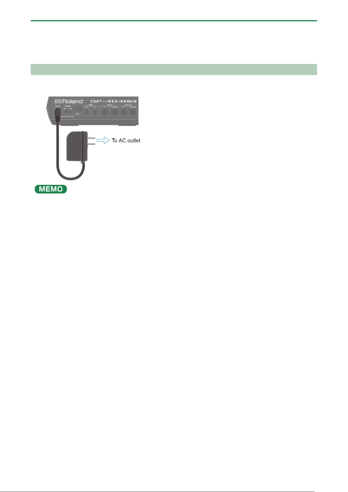
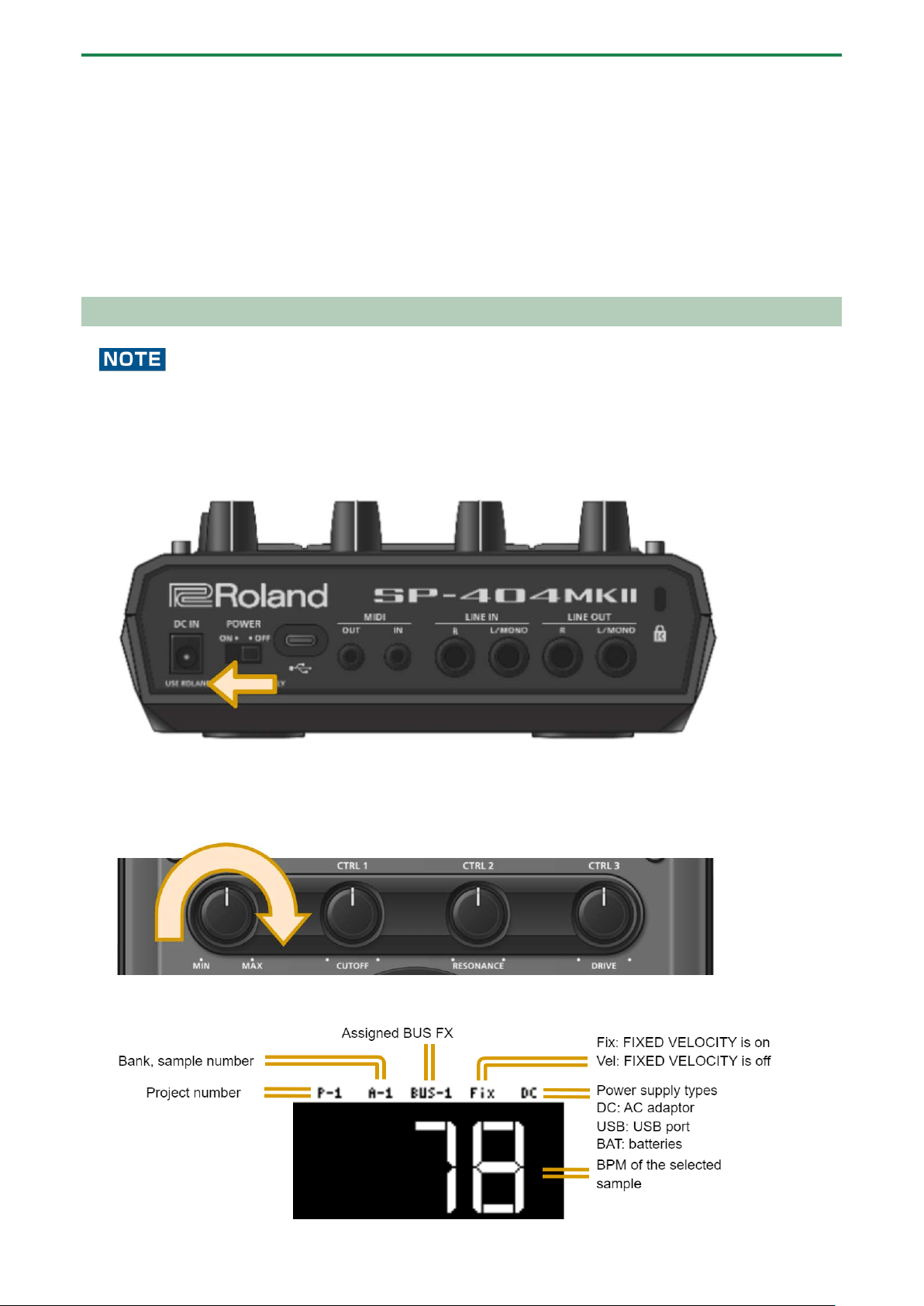
About the Power Supply
1.
Connect the included adaptor to the DC IN jack of this unit, and plug the adaptor into an AC outlet.
●
You can also use this unit without an adaptor, such as by supplying power to the USB port or by using batteries.
→ “Powering the Unit via USB Port(P.9)” “Using Batteries(P.8)”
● If the unit is using multiple power sources, the sources are prioritized in this order: DC IN jack (the included AC adaptor),
USB port, batteries.
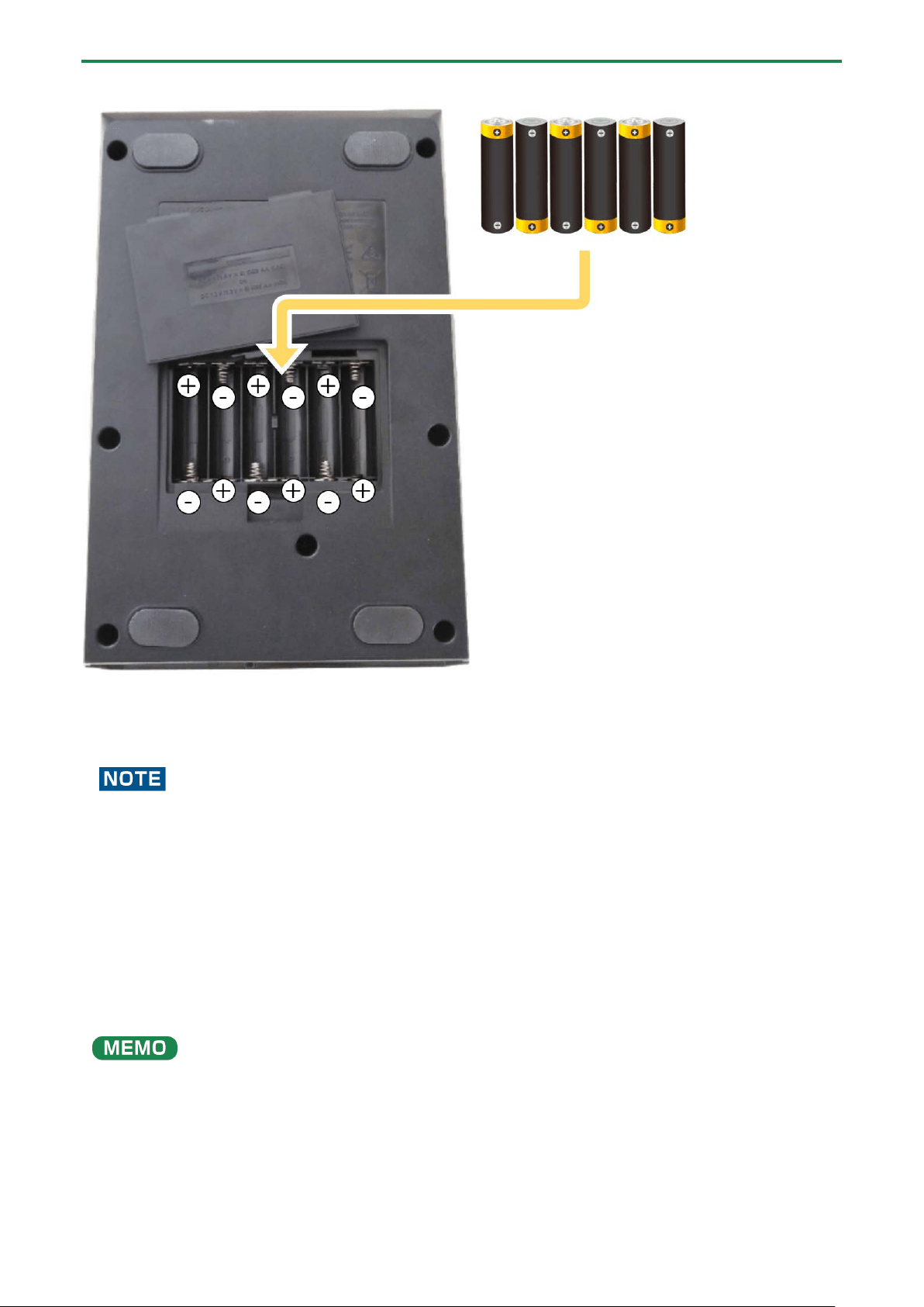
Using Batteries
Before installing/removing batteries, make sure to turn off the power to this unit and disconnect all connections to other devices.
When turning the unit over, be careful so as to protect the buttons and knobs from damage. Also, handle the unit carefully; do not
drop it.
Remove the battery compartment cover located on the bottom of this unit, and insert the batteries in the correct polarity
(direction) as marked inside the battery compartment.
Close the cover securely.
Introduction
9
This unit uses six AA batteries (rechargeable Ni-MH or alkaline).
The unit can run for 3.5 hours on rechargeable Ni-MH batteries (1,900 mAh), and for 2.5 hours on alkaline batteries. (Note that
these times may differ depending on the conditions of use and of the batteries.)
If you handle batteries improperly, you risk explosion and fluid leakage. Make sure that you carefully observe all of the items
related to batteries that are listed in leaflet “Read Me First” (USING THE UNIT SAFELY.)
Powering the Unit via USB Port
You can power this unit with a commercially available USB adaptor, from the USB port on your computer and from similar sources.
The following USB power sources can be used.
● USB AC adaptor
● USB bus power (computer, etc.)
● Mobile battery
We cannot guarantee that this unit works universally with all USB AC adaptors, power from USB ports on computers or mobile
batteries.
Conditions for powering this unit via USB port
When supplying power to this unit via the USB port, be sure to use a cable with USB Type-C® connectors on both ends. No other
USB cables can be used, as they cannot provide enough power to operate the SP-404MK2. Also note that even when using cables
that have a USB Type-C® connector on both ends, you cannot power this unit from devices like USB hubs with insufficient current
output.
Introduction
10
The USB port on the device from which this unit draws power must supply 5 V of output voltage and at least 1.5 A of output
current.
When not enough power is supplied to the USB port
In the event that not enough power is supplied to the USB port of this unit (such as when you try to supply power from a USB
Type-A connector or when the output current is less than 1.5 A), the message “Switch to batteries” appears.
When this happens, press the [VALUE] knob to switch to battery power. Note that if there are no batteries installed, the unit
powers down.
Turning the Power On/Off
Before turning the unit on/off, always be sure to turn the volume down. Even with the volume turned down, you might hear
some sound when switching the unit on/off. However, this is normal and does not indicate a malfunction.
Turning the power on
1.
To turn on the power, slide the [POWER] switch of this unit to “ON”.
2.
Next, turn on any connected devices, and then the amp/speakers, in that order.
3.
Adjusts the volume of the connected instrument.
4.
Adjust the volume of this unit with the [VOLUME] knob.
About the sample mode display (top screen)
The top screen is shown once you turn on the power of the SP-404MK2 and the unit is ready to play.

Introduction
11
Turning the Power Off
1.
Turn the volume of this unit and of your amp and speakers all the way down.
2.
Turn off the power of your amp and speakers.
3.
Slide the [POWER] switch of this unit to “OFF” to turn off this unit.
Playing Back Samples (SAMPLE MODE)
12
Playing Back Samples (SAMPLE MODE)
There are many preset samples available on this unit by factory default.
When you turn on the SP-404MK2, the pads light up orange and the unit enters sample mode.
If the unit is not in sample mode, press the [EXIT] button a number of times.
When the pads are blinking blue, press the [EXIT] button a number of times and then press the [PATTERN SELECT] button.
1.
Press the pads of the SP-404MK2.
The corresponding samples play back.
●
Refer to “Sampling (SAMPLING)(P.37)” if you want to record a new sample.
● If you want to use samples that are already saved on your computer or other device, see “Importing Samples (IMPORT
SAMPLE)(P.116).”
About sample playback mode
The way that samples play back when you press the pads depends on the playback mode set for the samples.
For details on each playback mode, refer to the following.
Playback mode
Reference
Gate
Playing Back Only While a Pad is Pressed (GATE)(P.15)
One-shot playback
Playing Back Samples Only One Time (One-shot Playback)(P.16)
Loop
Playing Back Samples Repeatedly (LOOP)(P.17)
Selecting a Sample Bank
Select the bank to use from the 10 available banks (A–J).
1.
Press the bank [A/F]–[E/J] buttons.
The bank switches.
Each time you press the bank [A/F] button, the bank switches between A and F.
When bank A–E is selected, the bank [A/F]–[E/J] button lights up. When bank F–J is selected, the bank [A/F]–[E/J] button
blinks.

Playing Back Samples (SAMPLE MODE)
13
Adjusting the Volume for All Banks (BANK VOLUME)
Adjusts the volume for the specified bank overall. This lets you adjust the volume if the volume varies between banks.
1.
Hold down the [SHIFT] button and press the bank [A/F]–[E/J] buttons.
The BANK VOLUME screen appears.
2.
Turn the [VALUE] knob to set the bank volume.
3.
When you are finished adjusting the values, press the [EXIT] button.
You may notice a difference in playback volume when copying or exchanging samples between different banks, due to the
differences in the BANK VOLUME parameters set for each bank.

Playing Back Samples (SAMPLE MODE)
14
Playing Back a Sample to the Tempo of a Song (BPM SYNC)
You can synchronize the tempo (playback speed) of one sample with another sample.
You can also synchronize the tempo of a sample with that of an external device that’s playing, such as a musical instrument or
computer.
1.
Press the [BPM SYNC] button.
This turns BPM SYNC on. The tempo of the sample then synchronizes with the bank tempo or the project tempo. The
playback speed is adjusted so that the sample plays back at the right tempo.
●
Set which tempo is used as the sample’s base tempo for playback in the system parameters.
For details, refer to “Parameter Guide(P.123)”.
● To use BPM SYNC, you must first set the accurate tempo data for each sample.
For details, refer to “Setting the Tempo Data in a Sample(P.83)”.
● You can make BPM SYNC synchronize either to the bank tempo or to the project tempo.
For details, refer to “Setting the Tempo for a Bank or Project(P.85)”.
● To turn the BPM SYNC parameter on/off for all samples in a bank, press the [BPM SYNC] button while holding down the
[SHIFT] button.

Playing Back Samples (SAMPLE MODE)
15
Playing Back Only While a Pad is Pressed (GATE)
This switches the gate function on/off.
When the [GATE] button is on, samples play back only while the pads are pressed (gate playback).
When the [GATE] button is off, samples begin playing back each time a pad is pressed.
You can also use the gate function with the [EXT SOURCE] button.
● When the [GATE] button is turned on, the sound from the external device is output only while you are pressing the [EXT
SOURCE] button.
● When the [GATE] button is turned off, the sound from the external device is switched on/off each time you press the [EXT
SOURCE] button.
1.
Press the [GATE] button to switch the function on (the button is lit) and off (the button goes dark).
To turn the GATE parameter on/off for all samples in a bank, press the [GATE] button while holding down the [SHIFT] button.
Momentary gate control
Use the operations shown below to change how samples are played back.
Sample playback method
Operation
Stop the playback of samples whose GATE is off
Hold down the [EXIT] button and press pads [1]–[16].
Continue the playback of samples whose GATE is on
Press the [HOLD] button while holding down pads [1]–[16].
Hold down the [HOLD] button and press pads [1]–[16].

Playing Back Samples (SAMPLE MODE)
16
Playing Back Samples Only One Time (One-shot Playback)
When the sample playback mode is set to one-shot playback, the sample plays back once to the end when you press a pad.
The pad’s operations are disabled (ignored) until playback is finished.
Even if a phrase that’s shorter than the sample length is recorded in a pattern, the sample plays back to the end without returning
to the beginning (no retriggering).
This characteristic is useful for playing a long sample as a backing track.
1.
Hold down the [VALUE] knob and press the [GATE] button.
This sets the sample playback mode to “one-shot playback”.
The [GATE] button blinks slowly at this time.
The loop function turns off (and the [LOOP] button goes dark) when one-shot playback is on.
Playing Back Samples (SAMPLE MODE)
17
Playing Back Samples Repeatedly (LOOP)
Use the loop function to make a sample play back repeatedly. The loop settings can be made per sample.
When the [LOOP] button is turned on, the loop switches between playback and stopping with each press of the pad (trigger
playback).
When the [LOOP] button is off, samples play back from the beginning each time a pad is pressed.
When you hold down the [HOLD] button and press a pad (sample) whose loop is turned on, the sample plays back from the
beginning (retrigger). In this case, pressing the pad does not make the sample stop.
Samples that are playing back in a loop play back from the beginning, making it sound like the loop was momentarily canceled.
Setting the loop to play back forwards
1.
Press the [LOOP] button to turn the loop on (the button lights up).
The loop plays back forwards.
Setting the loop to play back in reverse
1.
Press the [LOOP] button to turn the loop on (the button lights up).
2.
Press the [REVERSE] button to turn reverse playback on (the button lights up).
The loop plays back in reverse.
Setting the loop to play back forwards and then backwards
1.
Hold down the [SHIFT] button and press the [LOOP] button.
The [LOOP] button blinks. The loop alternately plays back forwards and then in reverse.

Playing Back Samples (SAMPLE MODE)
18
Playing Back a Sample in Reverse (REVERSE)
You can use the reverse function to play back samples in reverse (from end to start).
1.
Press pads [1]–[16] to select the sample you want to play back in reverse.
2.
Press the [REVERSE] button to turn reverse playback on (the button lights up).
Doing this sets the sample to play backwards.
When you press the [REVERSE] button while a sample is playing back, the sample plays back in reverse.
The point (time) where reverse playback starts differs depending on the REVERSE TYPE settings.
See “Reverse Type(P.124)” in the system parameters for details.
Playing Back Samples (SAMPLE MODE)
19
Playing Back Samples in Detailed Steps (ROLL)
You can use the roll function to repeatedly play back samples at a set interval.
1.
Hold down the [ROLL] button and press pads [1]–[16].
The sample plays back as a roll.
You can play back up to four samples at the same time as a roll.
Using a roll during sample playback
You can make a sample roll while it is playing back.
1.
Press pads [1]–[16].
The sample plays back.
2.
Press the [ROLL] button to turn the roll on (the button lights up).
The sample plays back rolled.
3.
Press the [ROLL] button again to stop the roll while it is playing back.
The roll starts once you take your finger off the [ROLL] button after pressing it.
To play rolls with the correct timing, press the [ROLL] button just before the roll should begin, and take your finger off the
button at the desired timing.
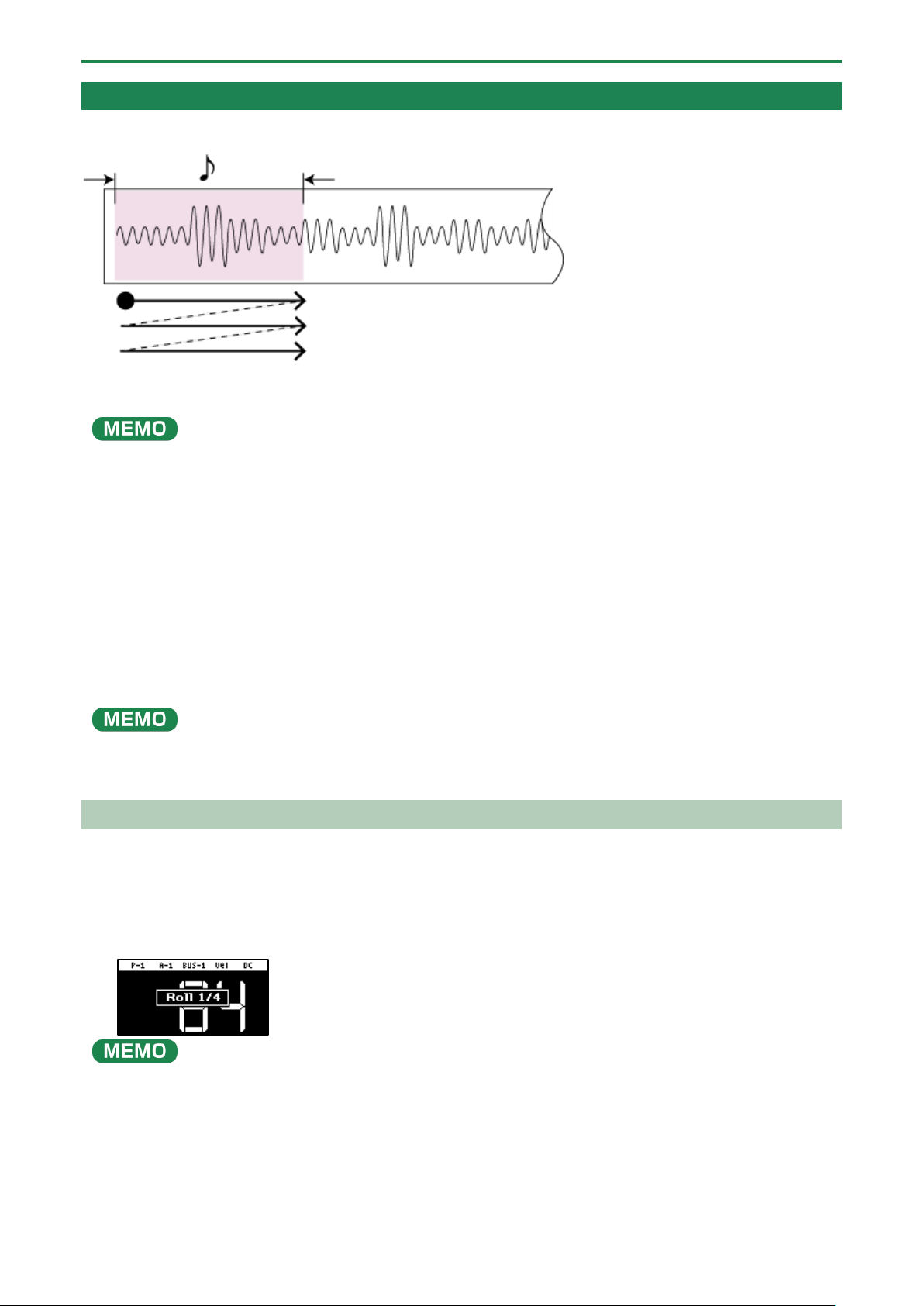
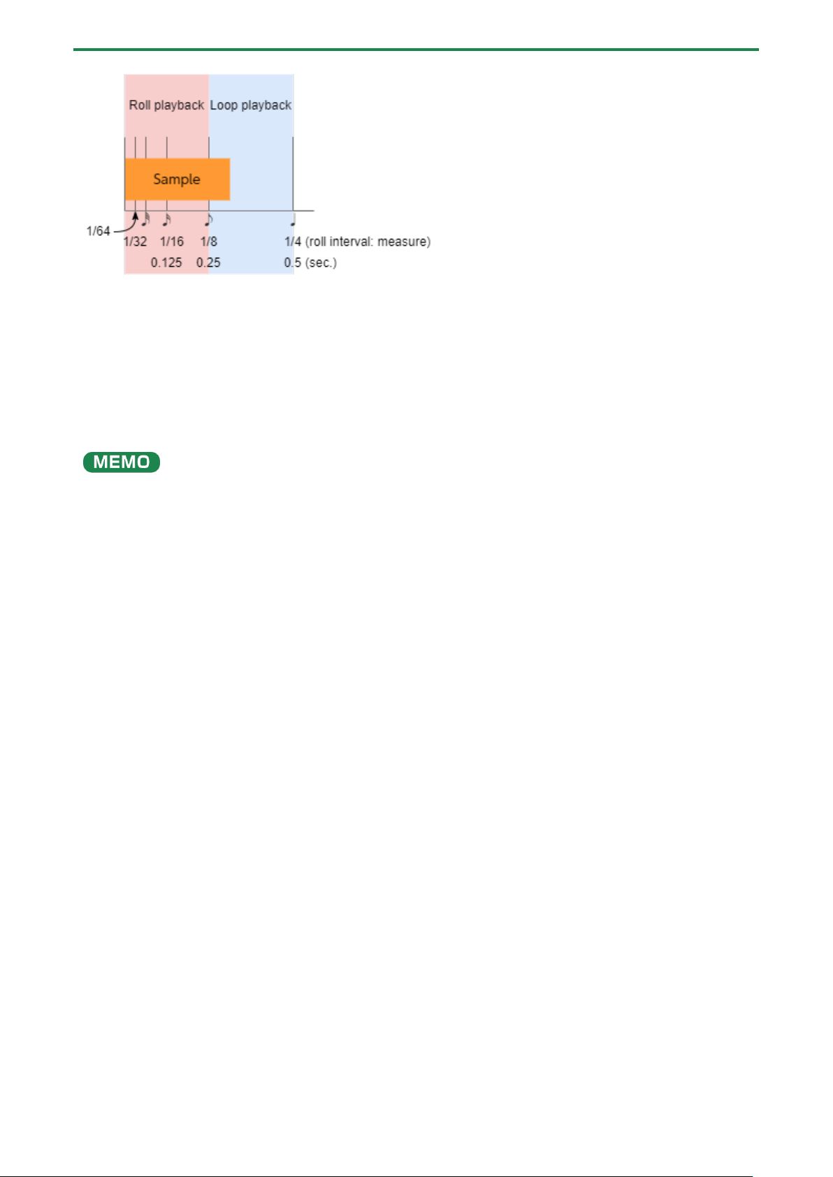
Setting the Roll Interval
This shows how to set the roll interval (how fast the roll repeats).
1.
Hold down the [SHIFT] button and press the [ROLL] button.
Set the roll interval. Each time you press the [ROLL] button while holding down the [SHIFT] button, the roll interval changes
as follows: quarter-note (1/4) Ó eighth note (1/8) Ó sixteenth note (1/16) Ó thirty-second note (1/32) Ó sixty-fourth note
(1/64).
If the roll interval (value) is longer than the sample length, the sample plays back in a loop.
The following are the conditions for roll playback or loop playback, when the tempo is 120 (bpm) and the sample length is less
than a quarter note (0.5 sec.).
Playing Back Samples (SAMPLE MODE)
20
When the roll interval is set to 1/64–1/8, the sample plays back as a roll.
When the roll interval is set to 1/4, the sample plays back in a loop.
Making the roll playback interval shorter (faster) partway through
You can shorten the roll interval while it is playing back.
1.
Follow the steps in “Playing Back Samples in Detailed Steps (ROLL)(P.19)” to make the sample roll.
2.
Hold down the [ROLL] button and turn the [VALUE] knob clockwise.
This shortens the roll interval. Turning the knob counter-clockwise returns the roll interval to its original value.
You can’t make the roll interval longer (slower) than the original value.

Playing Back Samples (SAMPLE MODE)
21
Setting a Fixed Sample Volume (FIXED VELOCITY)
You can set the sample’s velocity so that it always plays back at 127 (the maximum).
1.
Hold down the [SHIFT] button and press the pad [1].
“FIXED VELOCITY ON” is shown. The sample velocity is fixed at 127.
2.
To cancel this setting, hold down the [SHIFT] button again and press pad [1].
“FIXED VELOCITY OFF” is shown. The velocity changes (goes back to the original setting) according to how hard you play the
pads.
The FIXED VELOCITY setting can be set for each sample.
For details, refer to “Changing the Pitch or Playback Speed of a Sample (PITCH/SPEED)(P.52)”.

Playing Back Samples (SAMPLE MODE)
22
Changing the Sample Volume for Playback (16 VELOCITY)
You can use the 16 VELOCITY function to change a sample’s velocity (volume) in steps when it plays back.
1.
Press pads [1]–[16] to select the sample you want to use with the 16 VELOCITY function.
2.
Hold down the [SHIFT] button and press the pad [2].
The 16 VELOCITY screen appears.
3.
Press pads [1]–[16].
The pad position corresponds to the velocity shown. The sample plays back at the velocity that matches the pad you press.
4.
To exit 16 VELOCITY, press the [EXIT] button.
Playing Back Samples (SAMPLE MODE)
23
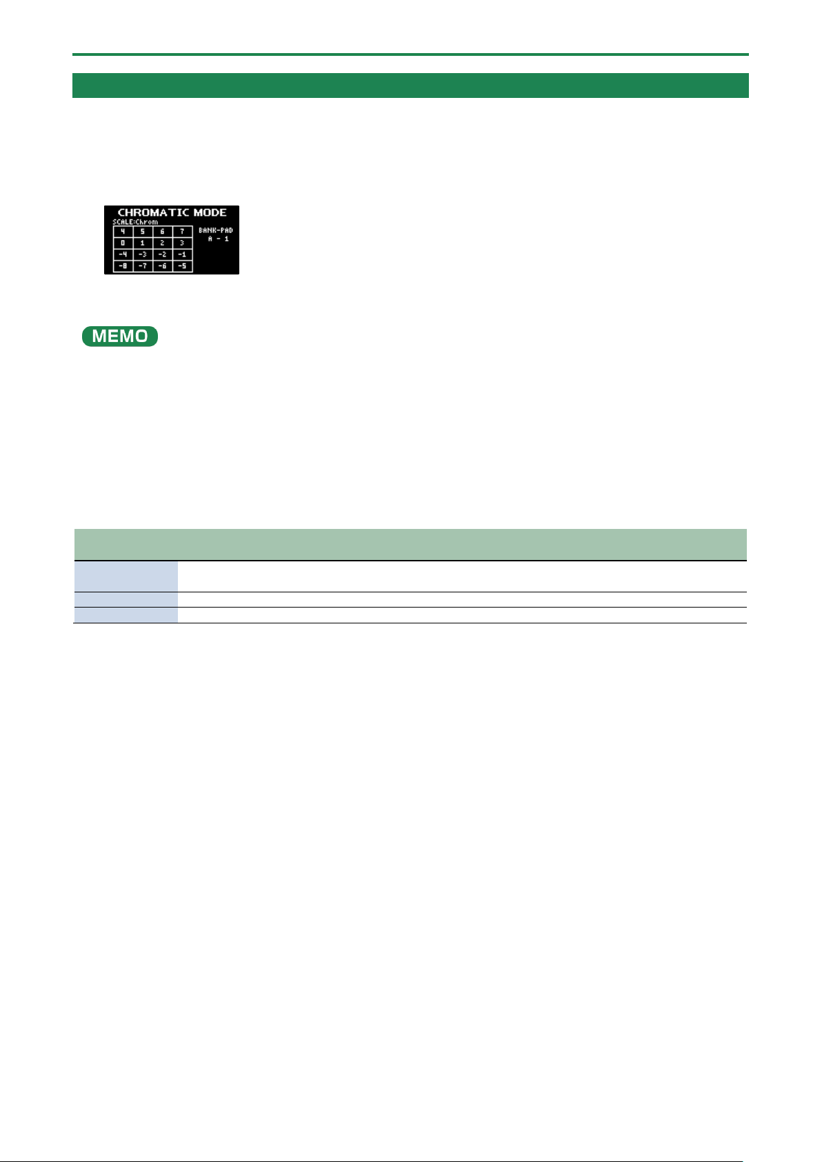
Playing Back Samples in Scale Pitches (CHROMATIC)
You can play back samples (changing their pitches) as a chromatic scale with the pads.
1.
Press pads [1]–[16] to select the sample to use in chromatic mode.
2.
Hold down the [SHIFT] button and press the pad [4].
The unit enters chromatic mode.
3.
Press pads [1]–[16].
The pad position corresponds to the key displayed. The sample plays back in the key that matches the pad you press.
Turn the [VALUE] knob to change the key range.
4.
To exit chromatic mode, press the [EXIT] button.
Changing how the samples play (how they sound)
You can change how samples play when they are triggered.
1.
In chromatic mode, press the [REMAIN] button.
The method switches each time you press the [REMAIN] button.
Method of
playing
[REMAIN]
button
Explanation
LEGATO
Blinks slowly
When you play legato (by pressing a pad while holding down another pad), portamento is
applied.
MONO
Lights up
The sample plays in single-note mode (monophonic).
POLY
Blinks quickly
Pressing multiple pads makes the samples play back at the same time (polyphonic).
Changing the scale/mode
You can change the scale/mode that’s used when you play.
1.
In chromatic mode, press the [VALUE] knob.
The scale/mode changes in the following order each time you press the [VALUE] knob.
Major scale → minor scale → Dorian mode → Phrygian mode → major scale → ...
Hold down the [ROLL] button and turn the [VALUE] knob to select the note (root) for the scale.

Playing Back Samples (SAMPLE MODE)
24
Muting the Playback of a Sample (PAD MUTE)
You can momentarily mute (silence) the playback of a sample.
By using part mute on a sample that’s playing back, you can create a break.
When a pattern is selected (the pad lights up purple), the pad can’t be muted. To mute a pad, press the [PATTERN SELECT]
button and switch to sample mode (the pad lights up orange).
1.
Press a pad to play its sample.
2.
Hold down the [SHIFT] button and [REVERSE] button and press the pad (sample) you want to mute.
The pad (sample) is muted. Muted pads (samples) light up red.
You can mute individual samples, either one or more than one, or mute individual samples when a pattern is playing back.
If you press the [REVERSE] and [REMAIN] buttons while holding down the [SHIFT] button, the [SHIFT] and [REVERSE] buttons
remain in a pressed-down state, even after you take your fingers off the buttons.
This makes it easier to mute or unmute multiple pads. Press the [EXIT] button to cancel this behavior.
3.
To unmute a pad, hold down the [SHIFT] button and [REVERSE] button and press the pad (sample) you
want to unmute.
You can also unmute a pad by pressing the [EXIT] button four times to stop the sample playback.
When PAD MUTE (SYSTEM parameter) is set to “MASTER,” the sound of the pad can be output from the PHONES jack, even if the
pad (sample) is muted (this lets you monitor the sounds from the pads). In this case, no effects are applied.
Refer to the “Pad Mute(P.123)” SYSTEM parameter for details.

Playing Back Samples (SAMPLE MODE)
25
Playing Back Multiple Pads at the Same Time (PAD LINK GROUPS)
The PAD LINK GROUPS function lets you group multiple pads (up to four) into one group. By setting a group ahead of time, you
can make all the pads in the group play back just by operating a single pad within that group.
You can also register up to 10 groups (A–J).
1.
Hold down the [SHIFT] button and press the pad [7].
The PAD LINK GROUPS screen appears.
2.
Turn the [VALUE] knob to select the group (A-J).
3.
Press pads [1]–[16] to select the samples you want to include in the group.
4.
To finish making setting, press the [EXIT] button.
5.
Press one of the pads that you set in the group.
All the pads in the group play back at the same time.

Playing Back Samples (SAMPLE MODE)
26
Preventing Samples from Playing Back at the Same Time (MUTE GROUP)
The MUTE GROUP function lets you group together all the samples that should not play at the same time (in other words, the
samples you don’t want to layer).
When you try and play the samples within that group all at the same time, only the sample that started playing back last is heard.
A group can consist of up to 16 samples. You can also register up to 10 groups (groups A–J).
1.
Hold down the [SHIFT] button and press the pad [8].
The MUTE GROUP screen appears.
2.
Turn the [VALUE] knob to select the group (A-J).
3.
Press pads [1]–[16] to select the samples you want to include in the group.
4.
To finish making the settings, press the [EXIT] button.
Out of the pads (samples) in the same group, sound is played back only for the last pad you play.
Playing Back Samples (SAMPLE MODE)
27
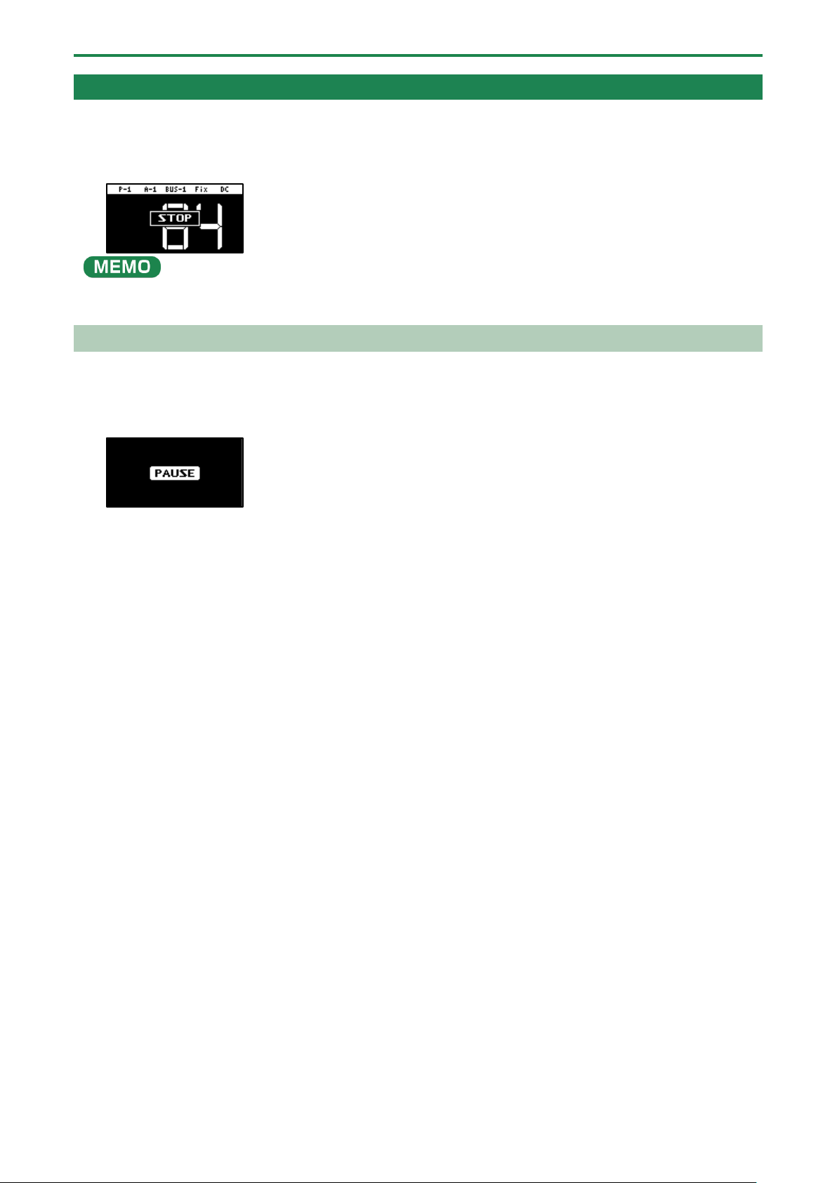
Stopping All Sample Playback (STOP)
You can make all samples and patterns that are currently playing back stop.
1.
Press the [EXIT] button quickly four times.
All samples and patterns that are playing back stop.
You can also press the [EXIT] button while holding down the [SHIFT] button to stop all samples and patterns that are playing
back.
Pausing the Sound of a Sample (PAUSE)
You can make samples that are currently playing back pause.
1.
Hold down the [SHIFT] button and press the [HOLD] button.
All samples that are playing back pause.
2.
Hold down the [SHIFT] button and press the [HOLD] button again to resume playback.
The samples resume playback.

Playing Back Samples (SAMPLE MODE)
28
Disabling Buttons that Are Not Used When Playing Live (LIVE MODE)
Normally, the buttons related to features like sampling and editing are not used when you are playing live.
Accidentally pressing these buttons while you’re performing live might be a show-stopper.
By turning live mode on, you can disable these buttons and avoid such accidents.
1.
Hold down the [SHIFT] button and long-press the [REMAIN] button for at least three seconds.
This turns live mode on, and the “ ” icon appears in the lower left corner of the screen.
The following buttons are disabled in live mode.
[DEL] button
[REC] button
[RESAMPLE] button
[COPY] button
[MARK] button
To turn live mode off, perform the same operation as described above.
Using the Effects
29
Using the Effects
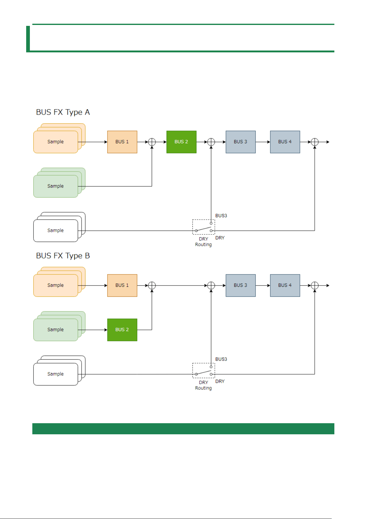
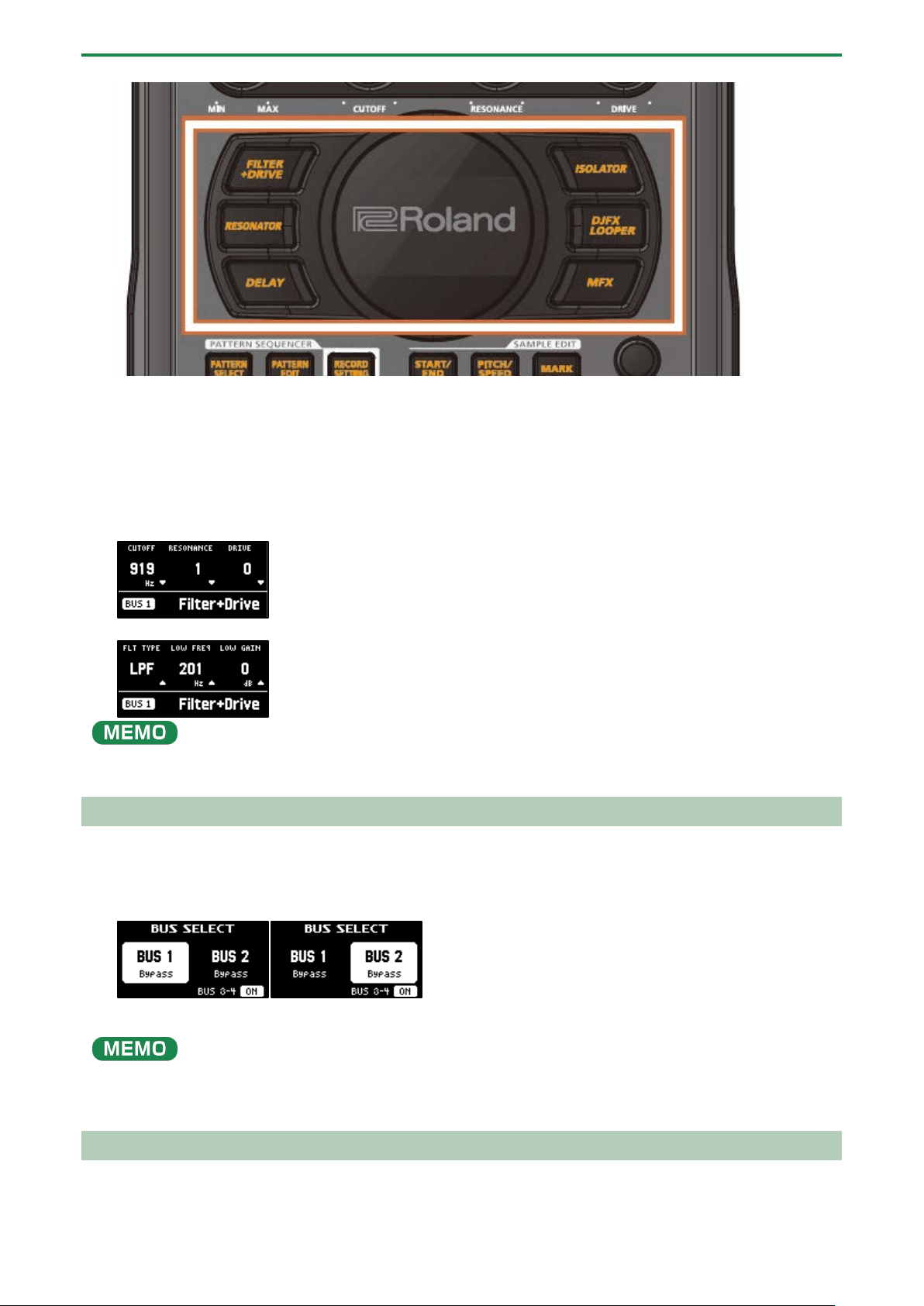
You can use the built-in effects on the SP-404MK2 to process the audio in unique ways.
Use the built-in effects on the SP-404MK2 by assigning them to a bus (an audio routing inside the SP-404MK2).
With BUS 1 and BUS 2, you can apply the effects that are appropriate for your performance, per sample. BUS 3 and BUS 4 are
mainly used to apply effects to the overall sound output from the SP-404MK2.
There are two kinds of bus routings (in connection order) that you can select as you like.
Refer to “Configuring the Effect Routing(P.108)” for how to edit the bus routings.
To switch between DRY Routing parameters, see “DRY Routing(P.128)” in EFX SET.
Adding Effects to a Sample (BUS FX)
You can use the various effects built into the SP-404MK2 to process the playback audio in unique ways.
1.
Press the effect buttons.
Using the Effects
30
Press the buttons of the effects you want to apply, including the [FILTER+DRIVE] button, the [RESONATOR] button, the
[DELAY] button, the [ISOLATOR] button, the [DJFX LOOPER] button, and the [MFX] button.
This turns the effects on.
2.
Press pads [1]–[16] to play back the samples.
Effects are applied to the samples.
3.
Use the [CTRL 1]–[CTRL 3] knobs to adjust the parameters.
The parameters change how the effects are applied.
You can also access the effect sub-parameters by holding down the [VALUE] knob and operating the knobs.
You can assign the effects you like to the effect buttons.
For details, refer to “Assigning the Desired Effect to an Effect Button (DIRECT FX)(P.111)”.
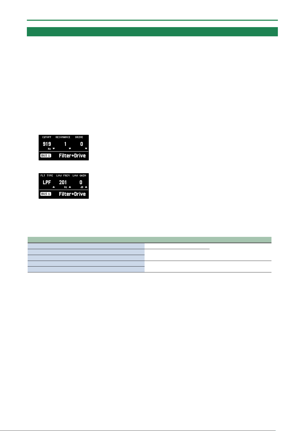
Assigning Effects to BUS 1 and BUS 2
Here’s how to assign the built-in effects of this unit to BUS 1 or BUS 2. You can use two types of effects separately.
1.
Press the [BUS FX] button to select the bus to configure.
When the button is lit orange, BUS 1 is selected; and when the button is blinking orange, BUS 2 is selected.
2.
Press the [FILTER+DRIVE]–[MFX] buttons to select the effect to assign to the bus.
You can assign the built-in effects of this unit to BUS 3 or BUS 4. Up to four effects are available.
To assign an effect to BUS 3 or BUS 4, change the settings in the effect setting screen.
→
“Configuring the Effect Settings (EFX SET)(P.108)”
Deciding on Effects to Use for Each Sample
Sets which sample playback audio is sent to which bus (meaning which effects are used) for each sample.
In this example, we apply the effect assigned to BUS 2 to the sample on pad [1].
Using the Effects
31
Set which effect is applied to the bus beforehand. For details, refer to “Assigning Effects to BUS 1 and BUS 2(P.30)”.
1.
Press the [BUS FX] button to select BUS 2.
2.
Hold down the [REMAIN] button and press the pad [1].
The playback audio for the sample assigned to pad [1] is sent to the effect assigned to BUS 2.
Pad [1] lights up green at this time.
The pad’s color tells you the bus to which the sample is sent.
Pad color
Audio send destination (bus)
Lit orange
BUS 1
Lit green
BUS 2
Lit white
The sound is not sent to BUS 1 or BUS 2 (DRY).
Preventing samples from being sent to BUS 1/BUS 2
You can prevent the playback audio of samples from being sent to BUS 1 or BUS 2 (DRY). In this case, no effects are applied to the
samples.
1.
While holding down the [REMAIN] button, press the pad [1]–[16] buttons a number of times to make
them light up white.
The BUS 1 and BUS 2 effects are not applied to the samples of pads that are lit up white.
Sending the audio input from the INPUT jack to a bus
As with the samples, you can set the bus to which the playback audio signals coming into the INPUT jack are sent (meaning which
effects are used).
For details, refer to “Sending the Audio Input from the INPUT Jack to a Bus(P.113)”.
Using the MFX Effects
You can select and use the effects you like for the MFX effects.
1.
While holding down the [MFX] button, turn the [VALUE] knob or the [CTRL 3] knob to select the effect to
use.
You can also use pads [1]–[16] instead of the [VALUE] knob or the [CTRL 3] knob to select an effect.
To use pads [1]–[16] to select effects from #17 and up, hold down the [MFX] button and the [DJFX LOOPER] button at the same
time.
2.
After selecting the effect, take your finger off the [MFX] button.
The effect turns on, and the effect edit screen appears.
3.
Play back a sample.
4.
Use the [CTRL 1]–[CTRL 3] knobs to adjust the parameters.

Using the Effects
32
You can also access the effect sub-parameters by holding down the [VALUE] knob and operating the knobs.
Using the Effects
33
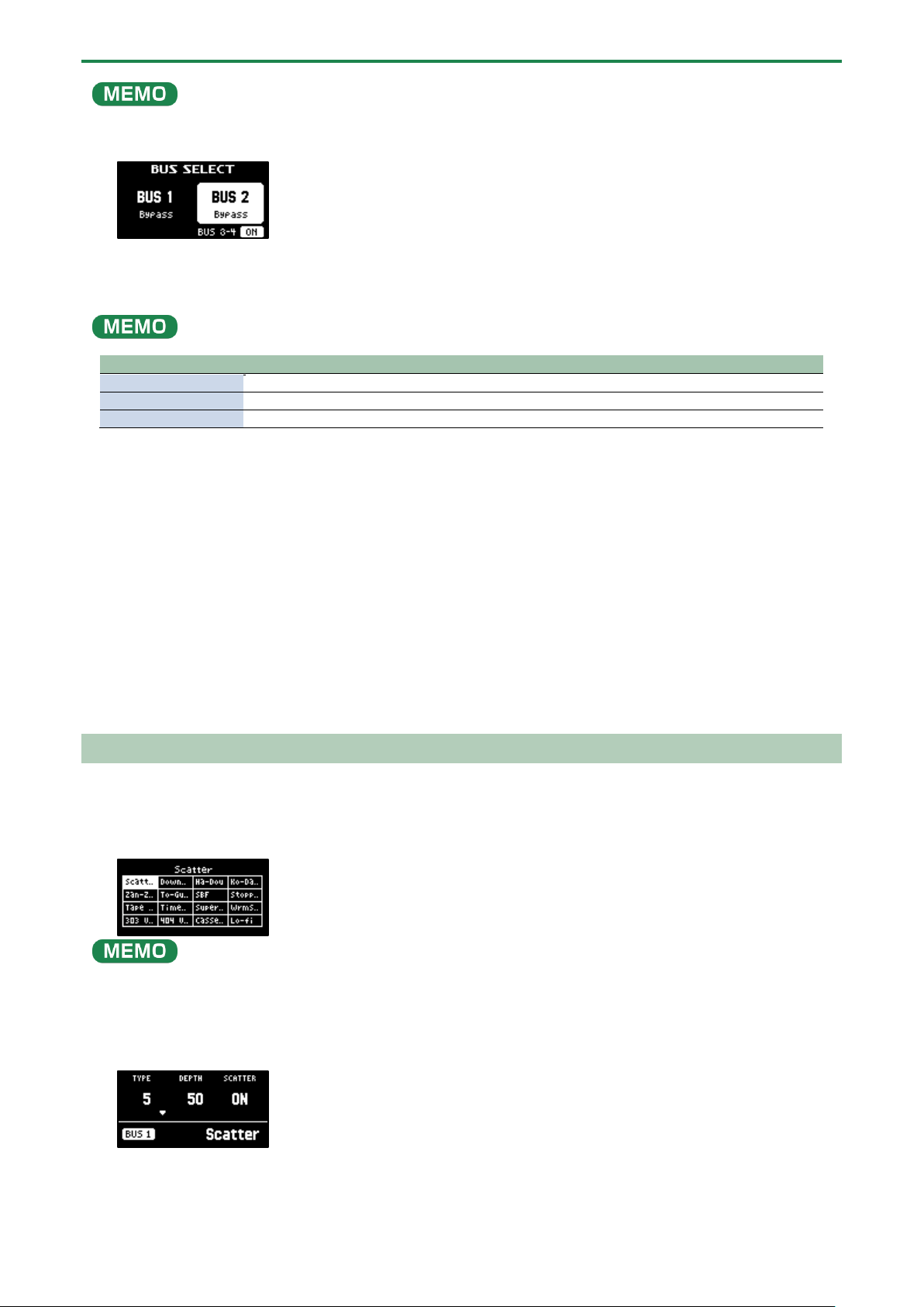
Editing the Effects
When you press an effect button (such as the [FILTER+DRIVE] button) to turn the effect on, the effect edit screen appears.
Turn the [CTRL 1]–[CTRL 3] knobs while the effect edit screen is displayed to edit the main parameters of the effect.
You may be able to access the sub-parameters by holding down the [VALUE] knob, depending on the effect. Turn the [CTRL 1]–
[CTRL 3] knobs to edit the sub-parameters of the effect.
Locking the effect edit screen
Although the effect edit screen displays when you press an effect button, the screen normally returns to the previous screen if you
don’t operate any controls for several seconds.
You can use the following operation if you want to make the effect edit screen keep displaying.
1.
While holding down the [REMAIN] button, press an effect button (such as the [FILTER+DRIVE] button).
The effect edit screen appears. Even if you don’t operate the unit for a while after this, the unit does not return to the
previous screen.
The display switches between main parameters and sub-parameters each time you press the [VALUE] knob, depending on
the effect.
2.
To exit the settings, press the [EXIT] button or the [REMAIN] button.
How the effect parameters are saved and shared
Parameters that are retained even after you turn off the power of this unit are shown below.
Bus to which effects are assigned
Main parameters
Sub-parameters
INPUT (INPUT FX)
µ
µ
BUS 1
µ (*)
BUS 2
BUS 3
µ µ
BUS 4
(*) The main effect parameters assigned to BUS 1 and BUS 2 are saved when you hold down the [MARK] button for at least three
seconds while holding down the [SHIFT] button.
The effect parameters on this unit are shared in common with some buses to which effects are assigned.
For instance, the sub-parameters of effects assigned to INPUT, BUS 1 and BUS 2 are shared in common. For this reason, when you
assign the same effect to INPUT and BUS 1 and then change the INPUT FX sub-parameters, the BUS 1 sub-parameters become the
same values.
The effect parameters are likewise shared between BUS 3 and BUS 4 as well.

Using the Effects
34
Turning Effects On/Off at the Desired Timing
You can make effects apply only while you hold down the effect buttons (EFFECT GRAB).
This lets you quickly turn an effect on/off in time with what you play.
1.
Play back a sample.
2.
While holding down the [VALUE] knob, press an effect button (such as the [FILTER+DRIVE] button).
The effect turns on only while you’re pressing the effect button.
Using the Effects
35
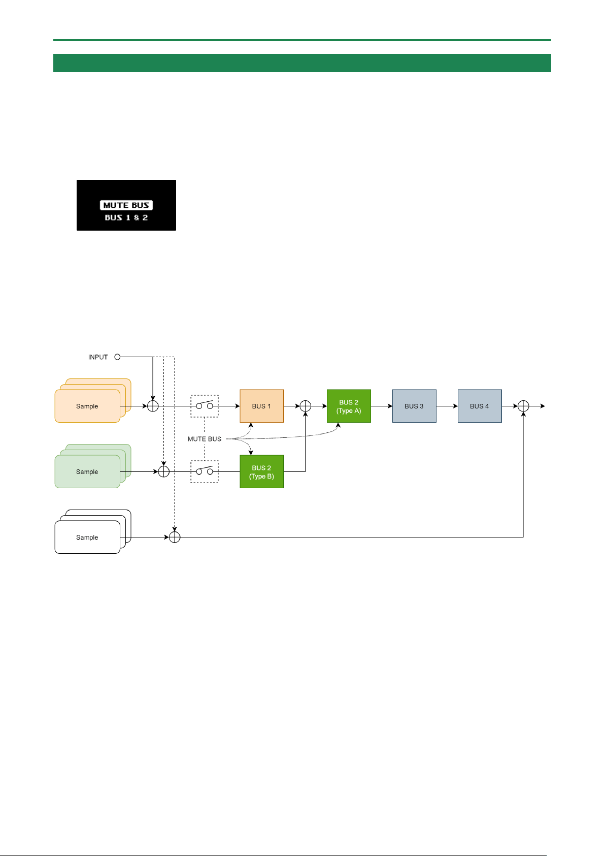
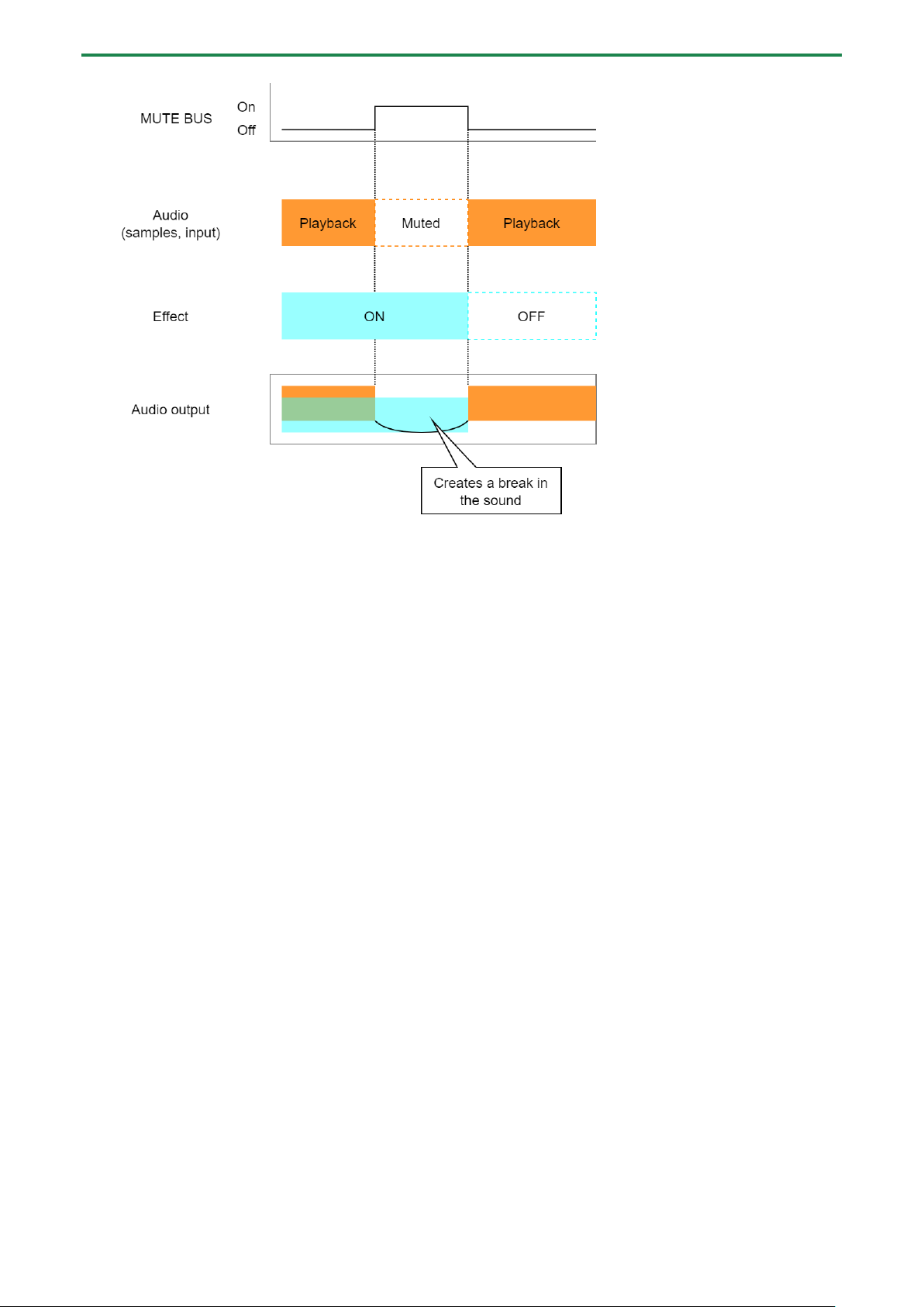
Temporarily Output Only the Effect Sound (MUTE BUS)
You can temporarily mute the audio (the sample playback sound or the audio coming into the INPUT jack) that’s sent to a bus, and
output only the sound of the effect.
This lets you output just the sound of reverberation or delay feedback to create a break when you’re playing.
1.
Play back a sample.
2.
Hold down the [SHIFT] button and press the [BUS FX] button.
MUTE BUS turns on. This shuts off the audio signal sent to the bus.
3.
To turn MUTE BUS off, hold down the [SHIFT] button and press the [BUS FX] button again.
MUTE BUS turns off. This allows the audio signal to be sent to the bus. At the same time, the effects assigned to the bus turn
off.
How MUTE BUS works
The MUTE BUS feature works in a complex way to control the audio sent to the buses and the effects at the same time.
This shows the audio signal flow when using MUTE BUS.
Also, the diagram below shows how the audio outputted from this unit changes when you turn MUTE BUS on/off.
Sampling (SAMPLING)
37
Sampling (SAMPLING)
You can sample (record) the sound that’s inputted into this unit to create your own samples (audio data materials).
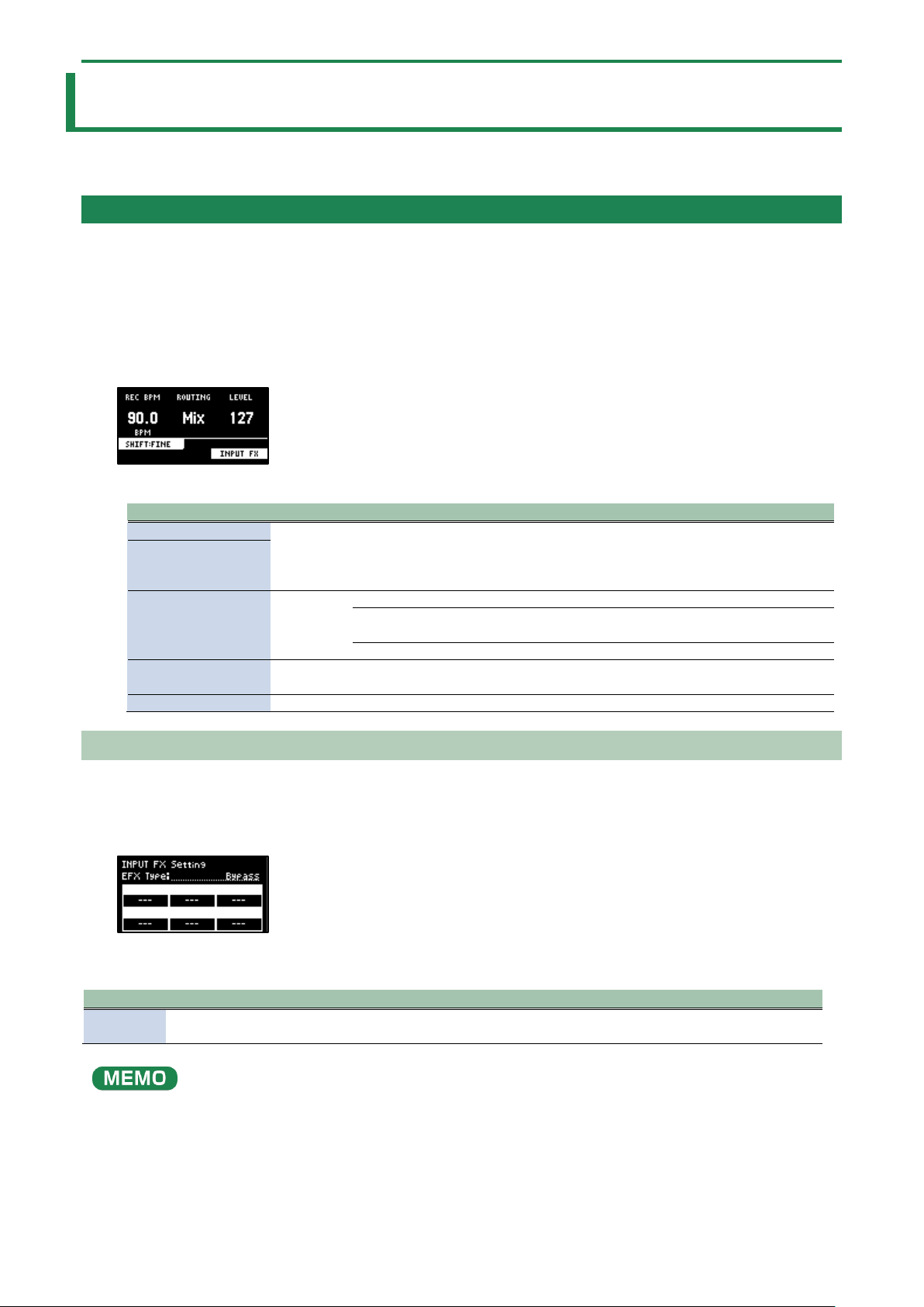
Configuring the Sampling Settings (RECORD SETTING)
Here you can configure the settings for sampling, such as the recording level, as well as apply input effects to the sound input
from an external source.
1.
In sample mode, press the [REC] button.
The unit enters sampling standby mode.
2.
Press the [RECORD SETTING] button.
The input setting screen appears.
3.
Use the controllers to edit the parameters.
Controller
Parameter
Value
Explanation
[CTRL 1] knob
REC BPM
40.0–
200.0
Specifies the tempo. Use the [CTRL 1] knob while holding down the
[SHIFT] button to set the value more precisely.
You can also set the tempo using the tap tempo function.
“Setting the Tempo in Time with the Rhythm (Tap Tempo)(P.86)”
[SHIFT] button +
[CTRL 1] knob
[CTRL 2] knob
ROUTING
This selects the source to sample (the input source).
Mix
Samples the mixed audio from this unit (the playback audio) and the
input from an external source.
ExtIn
Samples only the audio input from an external device.
[SHIFT] button +
[CTRL 3] knob
PAN
L:50–
R:50
Adjusts the pan position (the left-right volume balance when
sampling).
[CTRL 3] knob
LEVEL
0–127
Adjust the recording level.
Configuring the Input Effects (INPUT FX)
The INPUT FX (input effects) are effects used only for the input jacks. You can apply effects to the audio that’s inputted to this unit.
1.
On the input setting screen, press the [VALUE] knob.
The INPUT FX Setting screen appears.
2.
Use the [VALUE] knob to move the cursor to “EFX Type”, and press the [VALUE] knob.
The value display is highlighted, and you can now change the effects.
Parameter
Value
EFX Type
Bypass, Auto Pitch(*), Vocoder(*), Harmony(*), Gt Amp Sim(*), Chorus, JUNO Chorus, Reverb, TimeCtrlDly,
Chromatic PS, Downer, WrmSaturator, 303 VinylSim, 404 VinylSim, Cassette Sim, Lo-fi, Equalizer, Compressor
Effects marked with an (*) are for INPUT FX only.
3.
Use the [VALUE] knob to select the effect, and press the [VALUE] knob.
This sets the effect.

Sampling (SAMPLING)
38
4.
Use the [VALUE] knob to move the cursor to the parameter that you want to edit.
5.
Use the [CTRL 1]–[CTRL 3] knobs to adjust the parameters.
For details on the various effect parameters, refer to “MFX List(P.129)”.
Some effect parameters may be shared in common, depending on the bus to which the effect is assigned. For details, see “How
the effect parameters are saved and shared(P.33)”.
Sampling (SAMPLING)
39
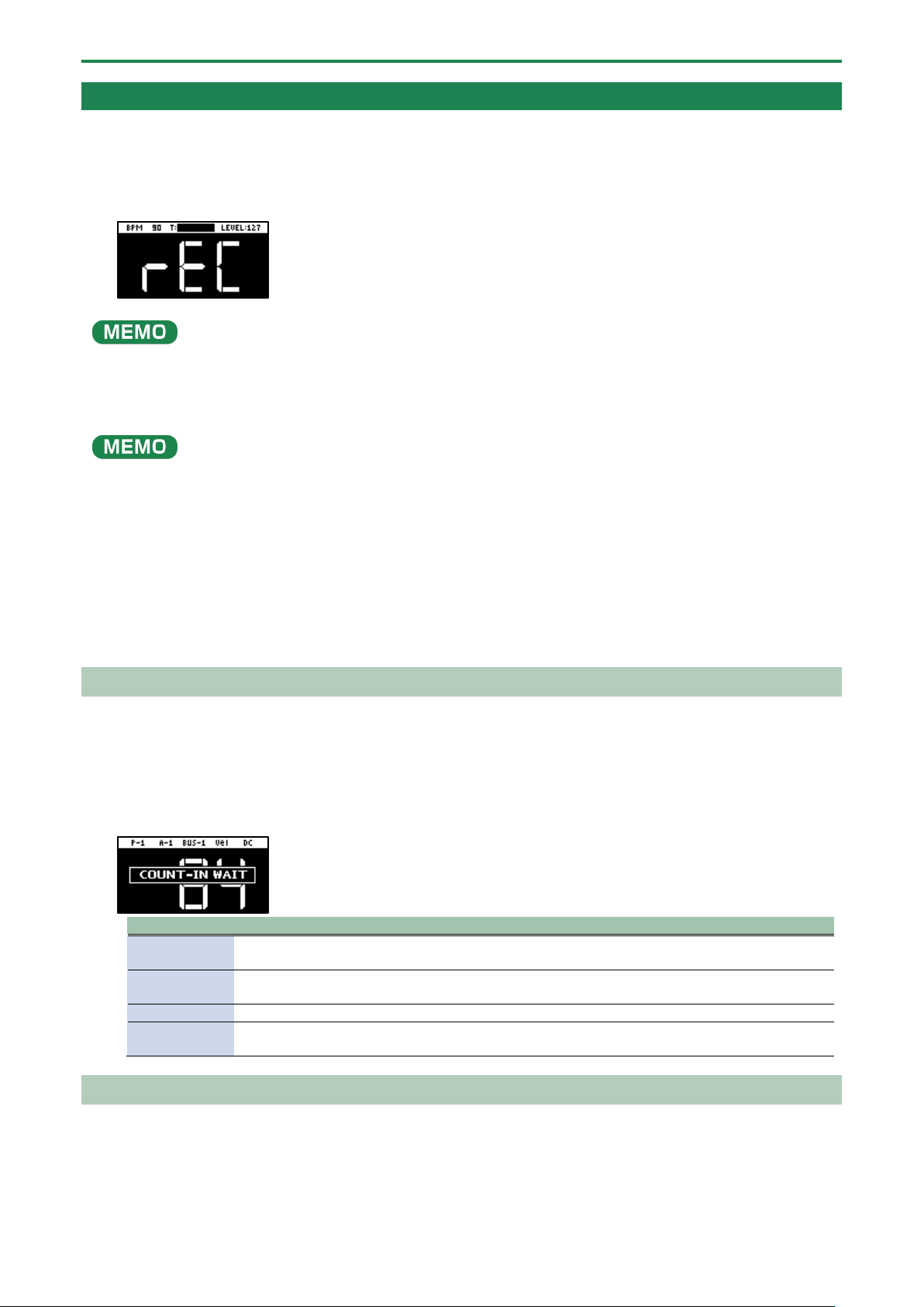
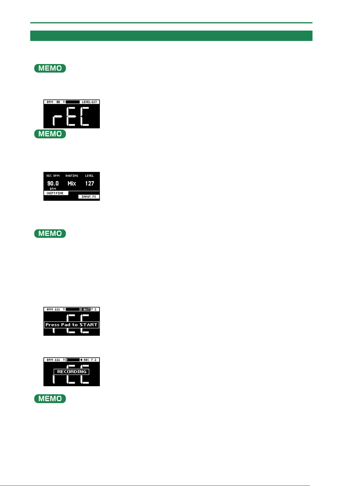
Sampling
This shows how to sample (record) the audio that’s inputted into this unit to create your own samples.
1.
Press the [REC] button.
Empty pads to which samples haven’t been assigned blink red.
The metronome sounds when the “Metronome:REC” parameter is “ON” (the SYSTEM parameter “CLICK(P.124)”).
Press pad [9] while holding down the [SHIFT] button to turn the metronome sound on/off.
2.
Use the [CTRL 1] knob to adjust the tempo during sampling (the sample tempo), and use the [CTRL 3]
knob to adjust the volume of audio input from an external device.
You can also set the tempo using the tap tempo function. For details, refer to “Setting the Tempo in Time with the Rhythm (Tap
Tempo)(P.86)”.
3.
Press the pads [1]–[16] that are blinking red.
4.
Press the [REC] button.
Sampling begins.
If you decide to cancel sampling, press the [EXIT] button.
5.
To quit sampling, press the pads [1]–[16] used for sampling or the [REC] button once more.
The sample is saved to the pad.
Adding a Count-in Before Sampling
This feature adds a count-in before sampling begins. This gives you time to get ready to play before sampling actually begins.
1.
Hold down the [SHIFT] button and press the pad [10].
The value changes in order each time you press pad [10] while holding down the [SHIFT] button.
Edit the count-in setting.
Value
Explanation
COUNTIN
1MEAS
Adds a one-measure count-in before sampling.
COUNTIN
2MEAS
Adds a two-measure count-in before sampling.
COUNTIN WAIT
When the input audio signal exceeds the level set in the Auto Trig Level parameter, sampling begins.
COUNTIN OFF
No count-in is used. Sampling starts immediately after you press the pads [1]–[16] to sample and
then press the [REC] button.
Automatically Setting the End Point of a Sample (END SNAP)
By setting the BPM (tempo) and then sampling, you can automatically set the beat that’s just before the sampling end beat as the
“end point” (the timing at which the sample stops).
1.
Press the [REC] button.
Empty pads to which samples haven’t been assigned blink red.
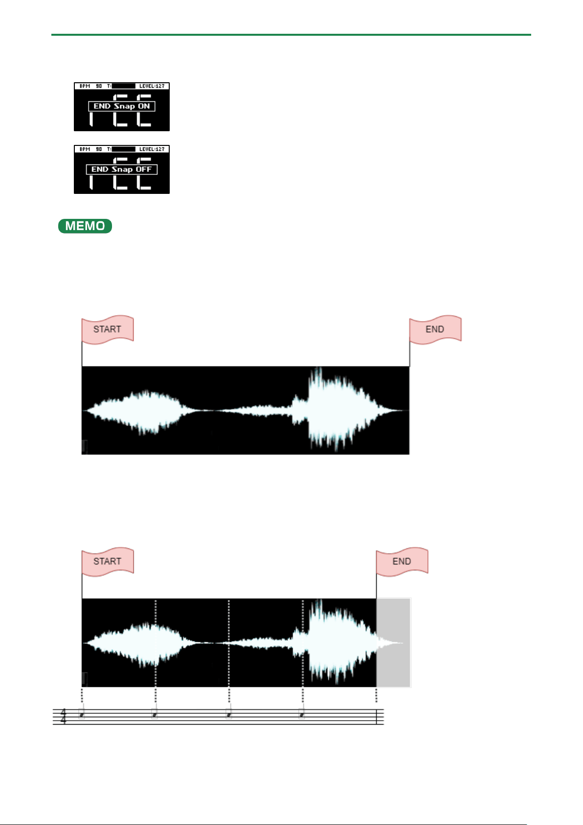
Sampling (SAMPLING)
40
2.
Press the [START/END] button.
END Snap is enabled. “END Snap ON” is displayed, and the [START/END] button lights up.
To disable END Snap, press the [START/END] button again. “END Snap OFF” is displayed, and the [START/END] button blinks.
3.
Sample by following steps 2 and onward in “Sampling (SAMPLING)(P.37)”.
You can use the END SNAP function when resampling or a rehearsing a pattern.
Sampling result when END SNAP is off
The end point is set at the end of the sample.
Sampling result when END SNAP is on
The end point is set at the beat near the end of the sample.
Sampling (SAMPLING)
41
Resampling a Sample (RESAMPLE)
Resampling means sampling a sample itself while it’s playing back. You can sample the sound of a sample to which effects are
applied, or sample the sound of multiple samples that are playing back at the same time, creating a single sample.
Also, by turning the pattern sequencer on beforehand (the [PATTERN SELECT] button lights up), you can resample a pattern in
the same way as you would resample a sample.
1.
Press the [RESAMPLE] button.
The metronome sounds when the “Metronome:REC” parameter is “ON” (the SYSTEM parameter “CLICK(P.124)”).
Press pad [9] while holding down the [SHIFT] button to turn the metronome sound on/off.
2.
Press the [RECORD SETTING] button.
The input setting screen appears.
3.
Use the [CTRL 2] knob to set ROUTING to “Mix”.
When ROUTING is set to “ExtIn”, only the audio input from an external device is sampled (the sample’s audio is not included in
the resample). You can sample your performance while playing back samples as backing sounds.
4.
Use the [CTRL 1] knob to adjust the tempo during sampling (the sample tempo), and use the [CTRL 3]
knob to adjust the volume of audio input from an external device.
5.
Press the [EXIT] button or the [RESAMPLE] button.
6.
Press pads [1]–[16] that are blinking red.
The empty pads to which samples haven’t been assigned blink red.
When you press an empty pad, the pad lights up orange, and a message “Press Pad to START” is shown.
7.
Press pads [1]–[16] to select a sample.
Sampling begins when the pattern starts playing back.
If you decide to cancel sampling, press the [EXIT] button.
You can also press the [REC] button to begin sampling. You can begin sampling when you want, while playing back samples as
backing sounds.
8.
To quit sampling, press the pads [1]–[16] used for sampling or the [REC] button once more.
The sample is saved to the pad.
Sampling (SAMPLING)
42
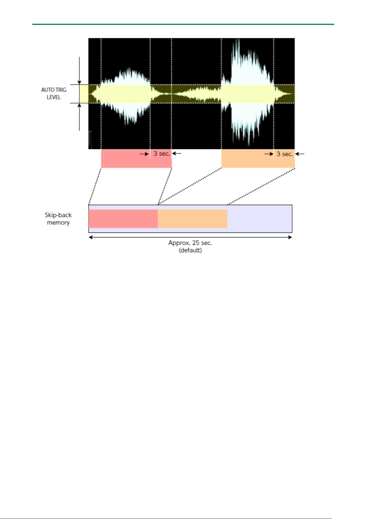
Sampling What You Previously Played (SKIP-BACK SAMPLING)
You can sample what you played up to 25 seconds ago (default) using the skip-back sampling function, which works even if you
hadn’t started sampling.
This lets you “go back in time” to sample a passage you played well during repeated practice, or to sample a phrase you played
well when you were just improvising.
1.
Play back a sample or pattern, or switch the [EXT SOURCE] button on and play the instrument that’s
connected to this unit.
When the unit detects an audio level at or above a certain level, the unit begins recording to skip-back memory (which is
used only for sampling past audio signals). At this time, the [MARK] button blinks.
2.
Press the [MARK] button.
After “SKIP BACK...” appears, the waveform of the audio in skip-back memory is displayed.
3.
Press the [REC] button.
“Select Pad To Save” appears. Empty pads to which samples haven’t been assigned blink red.
4.
Press pads [1]–[16] to select the pad to which you want to assign the skip-back memory audio.
Now the audio from skip-back memory is assigned to the pad.
Once you press the [EXIT] button without assigning the skip-back memory audio or turn off this unit, the skip-back
memory is lost.
If you want to keep the skip-back memory audio, make sure to assign it to a pad.
When you set the “SBS Time” system parameter to “Long”, the maximum time available for recording to skip-back memory can
be set to a maximum of 40 seconds.
See “SBS Time(P.123)” in the system parameters for details.
Skip-back sampling: how it works, and what its restrictions are
● Skip-back memory records up to 25 seconds (default) of audio. Anything recorded more than 25 seconds ago is
erased, and can’t be previewed or sampled.
● The skip-back memory audio starts and pauses recording according to the setting of the Auto Trig Level parameter.
When the input audio signal exceeds the level set in the Auto Trig Level parameter, skip-back memory starts
recording. When the input audio signal falls below the level set in the Auto Trig Level parameter for at least three
seconds, skip-back memory recording is paused.
● Skip-back memory is not recording if the [MARK] button is not blinking, and thus can’t be previewed or sampled. If
you press the [MARK] button at this time, the message “No SKIP BACK Trigger Data” is shown.
Sampling (SAMPLING)
43
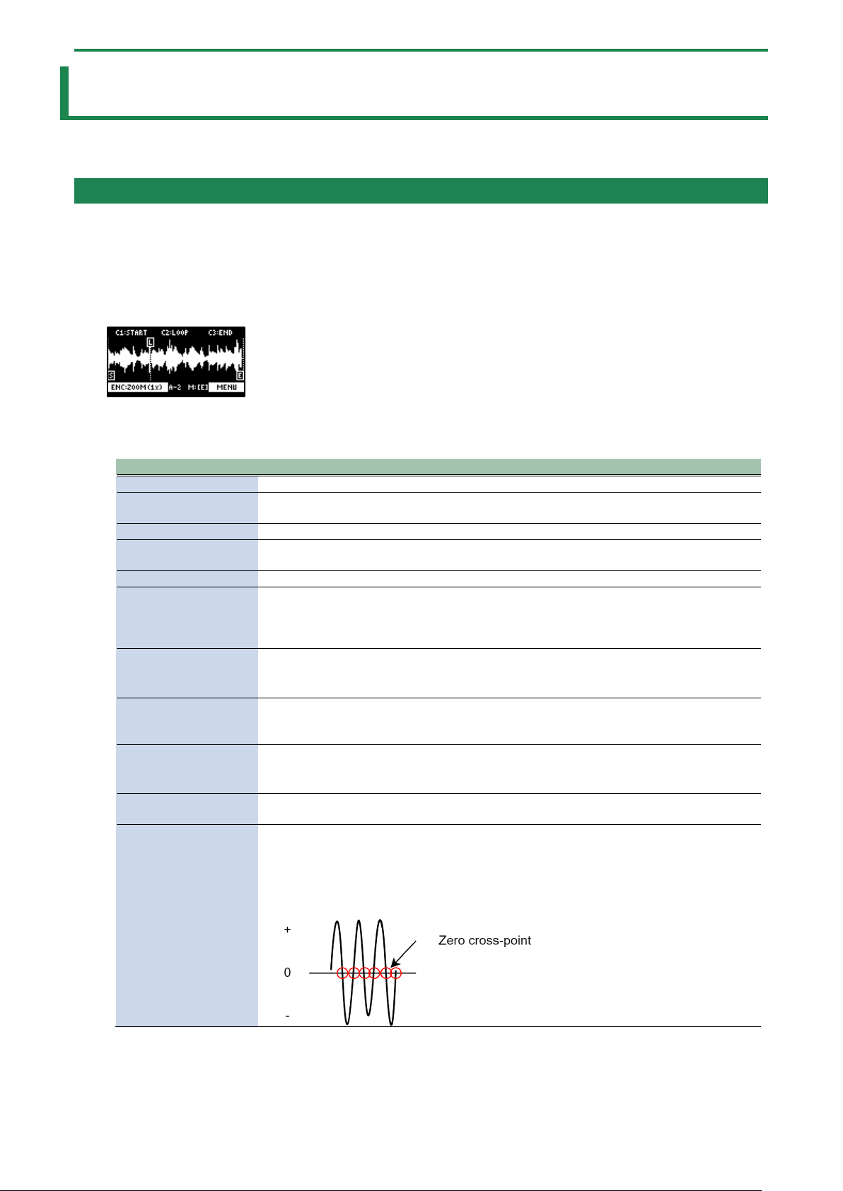
Editing a Sample (SAMPLE EDIT)
44
Editing a Sample (SAMPLE EDIT)
You can edit the playback speed, waveform and other parameters for the samples.
Setting the Playback and Loop Regions (START/END)
You can prevent unnecessary parts of a sample from playing, such as silence or noise at the beginning or at the end.
This shows you how to set the start point (where a sample begins playing back) and the end point (where a sample stops playing
back). You can also use the same operations to set the loop point (the starting point for loop playback).
1.
Press the [START/END] button.
The marker setting screen appears.
2.
Press pads [1]–[16] to select the sample you wan to edit.
3.
Use the [CTRL 1]–[CTRL 3] knobs to adjust the start and end points.
Controller
Operation
[CTRL 1] knob
Moves the start point.
[CTRL 2] knob
(when the loop is on)
Moves the loop point.
[CTRL 3] knob
Moves the end point.
[SHIFT] button + [CTRL]
knob (turn)
Zooms the area around each point in/out.
[VALUE] knob (turn)
Zooms the area in/out around each point you just manipulated.
[SHIFT] button +
[VALUE] knob (press)
You can use a numerical value to set the position of each point.
Use the [VALUE] knob to select the point to set, and press pads [1]–[10] to input the position
(press pad [10] to input a “0”).
To confirm the inputted position, press the [VALUE] knob.
[DEL] button
Initializes the start and end point positions.
● When a confirmation message appears, use the [VALUE] knob to select “OK”, and press
the [VALUE] knob.
[REMAIN] button
On: Prevents the start point from being moved beyond the loop point or the end point.
Off: When the start point moves beyond the loop point or the end point, this moves the
loop point or the end point as well.
[MARK] button
When this button is pressed while a sample is playing back, this sets the start point and end
point in order.
● The loop point is set to the same position as the start point.
[ROLL] button
While this button is pressed, you can preview the sound several seconds before the end
point.
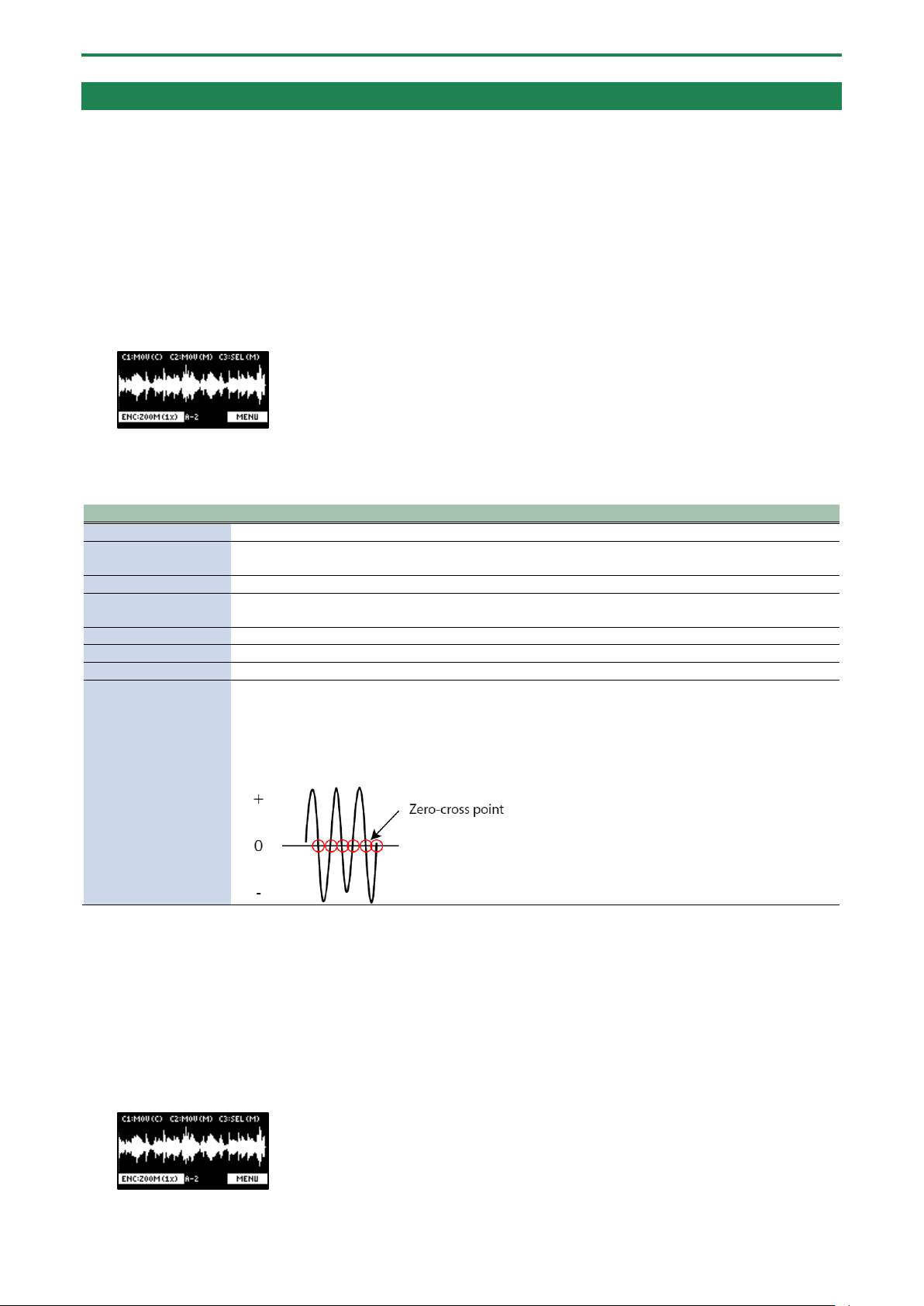
[RESAMPLE] button
Moves the start point to the zero cross-point (*) that’s closest to the start point time (SNAP
to Zero-Cross function).
Similarly, the loop point and end point are also moved.
This function is enabled when the [RESAMPLE] button is lit.
● The “zero cross-point” is the time at which the value of the sample waveform crosses
from zero into a positive or negative number.
4.
Once you’ve confirmed the start/end point, press the [EXIT] button.
Editing a Sample (SAMPLE EDIT)
45
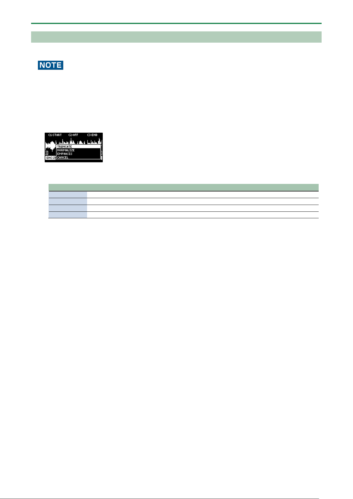
Processing a Sample
You can use the start point and end point settings to process a sample.
Note that this operation directly processes the original sample data. Once you process a sample in this way, it cannot be
restored.
1.
Set the start and end points by following the steps in “Setting the Playback and Loop Regions
(START/END)(P.44)”.
2.
Press the [VALUE] knob.
A menu appears.
3.
Use the [VALUE] knob to select the item, and press the [VALUE] knob.
The sample is processed.
Item
Action
TRUNCATE
Trims (deletes) the sample’s audio regions before the start point and after the end point.
NORMALIZE
Increases the overall volume.
EMPHASIS
Increases the high-frequency sound.
CANCEL
Closes the menu screen.
Editing a Sample (SAMPLE EDIT)
46
Marking and Splitting Samples (MARK)
You can split a sample up into multiple smaller samples. To split a sample, you must first mark the locations where the sample is to
be split using markers.
Here we explain about the different ways to add markers.
Adding a marker at the desired location
You can choose where to place a marker (the location where the sample is to be split) while looking at the sample’s waveform.
1.
Press pads [1]–[16] to select the sample to which you want to add markers.
2.
Hold down the [SHIFT] button and press the [START/END] button.
The marker setting screen appears.
3.
Decide on where to add the marker by using the [CTRL 1] knob, and then press the [MARK] button.
This adds the marker to the sample.
You can use the following controllers when the edit screen is shown.
Controller
Operation
[CTRL 1] knob
Moves the cursor (the location where a marker is placed).
[SHIFT] button + [CTRL
1] knob
Zooms the area around the cursor in/out.
[CTRL 2] knob
Moves the marker that you selected using the [CTRL 3] knob.
[SHIFT] button + [CTRL
2] knob
Zooms the area in/out around the marker selected using the [CTRL 3] knob.
[CTRL 3] knob
Selects the marker to operate.
[MARK] button
Adds a marker at the cursor location.
[DEL] button
Deletes the marker that you selected using the [CTRL 3] knob.
[RESAMPLE] button
Moves the cursor to the zero cross-point (*) that’s closest to the cursor time (SNAP to Zero-Cross
function).
This function is enabled when the [RESAMPLE] button is lit.
* The “zero cross-point” is the time at which the value of the sample waveform crosses from zero
into a positive or negative number.
You can press pads [1]–[16] to preview the audio at the corresponding marker.
Adding markers while previewing a sample
You can choose where to place a marker (the location where the sample is to be split) while previewing (listening to) the sample.
1.
Press pads [1]–[16] to select the sample to which you want to add markers.
2.
Hold down the [SHIFT] button and press the [START/END] button.
The marker setting screen appears.
3.
Press the pad [1].
Editing a Sample (SAMPLE EDIT)
47
The sample plays back.
4.
Press the pads [2]–[16] that are blinking blue, at the timing where you want to add a marker.
This adds the marker to the sample. You can press pads [1]–[16] to preview the audio at the corresponding marker.
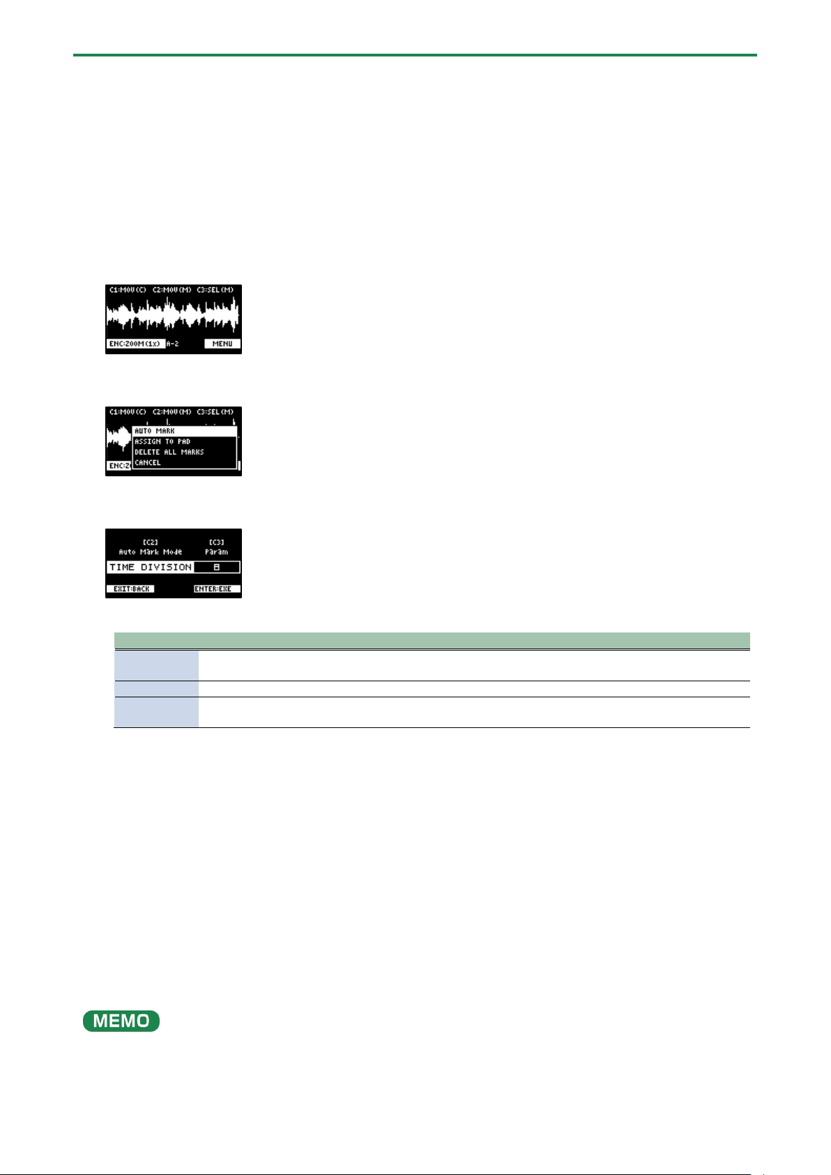
Automatically adding markers based on conditions (AUTO MARK function)
You can use the AUTO MARK function to automatically add markers based on certain conditions you specify.
1.
Press pads [1]–[16] to select the sample to which you want to add markers.
2.
Hold down the [SHIFT] button and press the [START/END] button.
The marker setting screen appears.
3.
Press the [VALUE] knob.
A menu appears.
4.
Use the [VALUE] knob to select “AUTO MARK”, and press the [VALUE] knob.
The AUTO MARK setting screen appears.
5.
Use the [VALUE] knob or [CTRL 2] knob to select a parameter.
Parameter
Value
Explanation
TIME
DIVISION
2–16
Adds markers by dividing up the sample equally.
LEVEL
1–10
Adds a marker at the location in the sample where the levels exceed a certain value.
TRANSIENT
HARD, MID,
SOFT
Adds a marker at the location in the sample where there is a large change in volume,
such as when a sound with sharp attack plays.
6.
Use the [CTRL 3] knob to edit the setting value, and press the [VALUE] knob.
A confirmation message appears.
7.
Use the [VALUE] knob to select “OK”, and press the [VALUE] knob.
The sample is split according to the specified conditions. You can press pads [1]–[16] to preview the audio at the
corresponding marker.
Deleting all markers from a sample
You can delete all the markers at once that are used on a sample.
1.
From the sample edit screen, press the [VALUE] knob.
A menu appears.
2.
Use the [VALUE] knob to select “DELETE ALL MARKERS”, and press the [VALUE] knob.
The markers are now deleted.
All markers are deleted, even if you exit the sample edit screen.
Editing a Sample (SAMPLE EDIT)
48
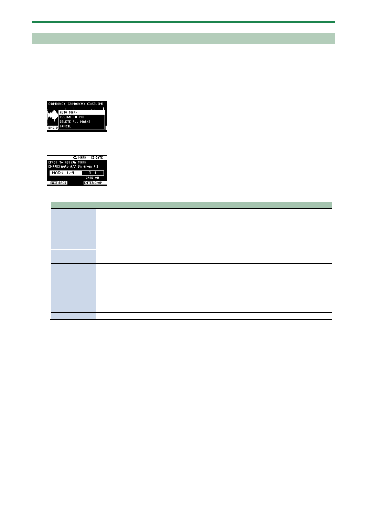
Using a Marker to Split and Assign a Sample to a Pad (CHOP)
Splits the sample at the marker positions, and assigns the resulting samples to separate pads.
1.
Follow the steps in “Marking and Splitting Samples (MARK)(P.46)” to add a marker where you want to split
the sample.
2.
Press the [VALUE] knob.
A menu appears.
3.
Use the [VALUE] knob to select “ASSIGN TO PAD”, and press the [VALUE] knob.
The assign screen appears.
4.
Set the parameters.
Controller
Explanation
Pads [1]–[16]
Selects the pads [1]–[16] to which you want to assign the split samples.
● The empty pads to which samples haven’t been assigned blink yellow.
When you press the empty pad to which you want to assign the sample, it lights up green.
● Pads to which samples have already been assigned light up dark orange.
If you press a pad for which a sample is already assigned, the pad lights up red. The assigned sample is
then overwritten.
[CTRL 2] knob
Selects the marker where the sample is to be split.
[CTRL 3] knob
Turns the GATE on/off.
Turn the
[VALUE] knob
Arranges the split samples in order, with the first pad number being the one you selected using the
[VALUE] knob. Press the [MARK] button to confirm the arrangement.
● This operation only confirms the pads to which the samples are to be assigned, without
actually assigning the samples. To assign a sample to a pad, you must press the [VALUE] knob
last.
● Before pressing the [MARK] button, you can switch the pad bank and change the pad bank to
which the sample is assigned.
[MARK] button
[DEL] button
Cancels the assignment of the sample you selected with the [CTRL 2] knob.
5.
Press the [VALUE] knob.
The split samples are assigned to the pads.
Editing a Sample (SAMPLE EDIT)
49
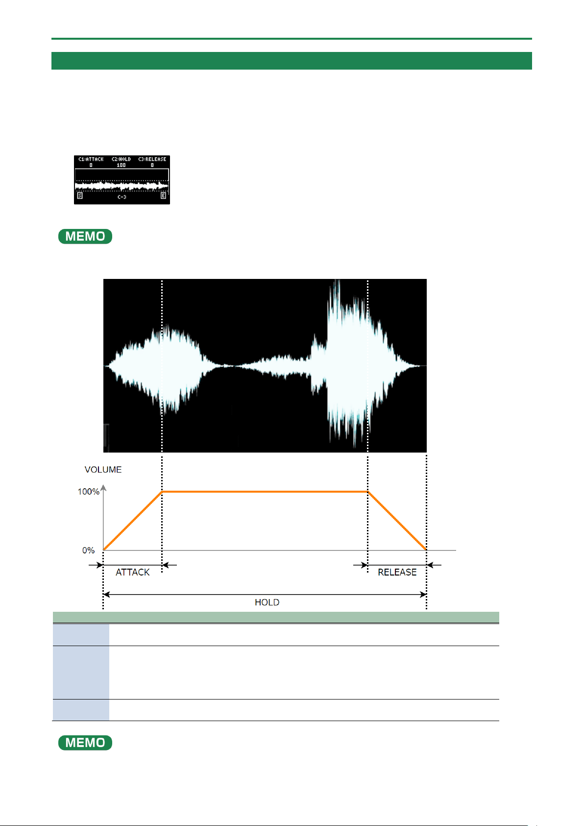
Making Fade-in/Fade-out Settings (ENVELOPE)
This shows how to set the changes in volume when playing back a sample.
You can use fade-in settings (making the volume gradually get louder) and fade-out settings (making the volume gradually get
softer).
1.
Hold down the [SHIFT] button and press the [PITCH/SPEED] button.
The envelope settings screen appears.
2.
Press pads [1]–[16] to select the sample you want to edit.
Press pads [1]–[16] while holding down the [MARK] button to select a sample without playing it back.
3.
Use the [CTRL 1]–[CTRL 3] knobs to set the fade-in and fade-out.
Controller
Parameter
Value
Explanation
[CTRL 1]
knob
ATTACK
0–127
Sets the fade-in time. When you set this to 127, the fade-in time is three
seconds.
[CTRL 2]
knob
HOLD
1–100
(%)
Sets the sample playback range.
The playback range is a ratio of how much of the sample is played back in
respect to its total length (considered to be 100).
When this is set to 50, the sample plays back from the beginning to the
middle, and fade-in and fade-out are applied within this range.
[CTRL 3]
knob
RELEASE
0–127
Sets the fade-out time. When you set this to 127, the fade-out time is three
seconds.
When you change the following parameters while holding down the [COPY] button, you can change the parameters of other
samples registered to the same mute group simultaneously.
Editing a Sample (SAMPLE EDIT)
50
When you change the following parameters while holding down the [REMAIN] button, you can change the parameters of other
samples registered to the same bank simultaneously.
● ATTACK
● HOLD
● RELEASE
● BPM SYNC
● GATE
● LOOP
● REVERSE
For details on the mute group settings, refer to “Preventing Samples from Playing Back at the Same Time (MUTE GROUP)(P.26)”.
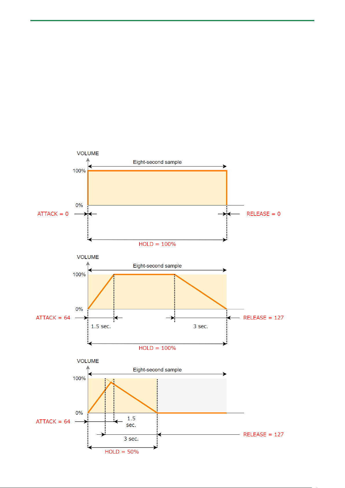
Example settings for ATTACK, HOLD and RELEASE
Here are some examples of how the volume of a eight-second sample changes when you set different ATTACK, HOLD and
RELEASE values.
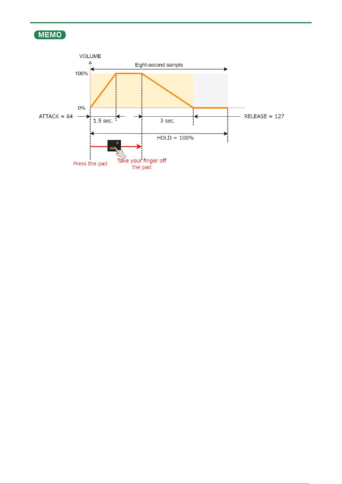
Editing a Sample (SAMPLE EDIT)
52
Changing the Pitch or Playback Speed of a Sample (PITCH/SPEED)
Here’s how to change the pitch (key) or playback speed of a sample. You can independently edit the pitch and playback speed, or
make a sample’s length match that of the tempo.
1.
Press the [PITCH/SPEED] button.
The pitch/speed settings screen appears.
2.
Press pads [1]–[16] to select the sample you want to edit.
3.
Use the [CTRL 1]–[CTRL 3] knobs to edit the parameters.
Controller
Parameter
Value
Explanation
[CTRL 1] knob
SPEED
50–150 (%)
Sets the playback speed.
● Use the [CTRL 1] knob while holding down the
[SHIFT] button to set more precise values.
● This can only be set when BPM SYNC is off.
[CTRL 2] knob
PITCH
-12.00–+12.00
(when VINYL MODE
is “No”)
-12.00–+7.00 (when
VINYL MODE is
“Yes”)
Sets the playback pitch.
[SHIFT] button +
[CTRL 2] knob
FINE
-1.00–+1.00 (CENT)
(when VINYL MODE
is “No”)
-0.49–+0.50 (CENT)
(when VINYL MODE
is “Yes”)
Lets you set a more precise value for the playback pitch.
[CTRL 3] knob
VOLUME
0–127
Sets the sample volume.
[SHIFT] button +
[CTRL 3] knob
PAN
MONO (Left), L:50–
R:50, MONO (Right)
Sets the stereo position (pan) of the sample.
Turn the [VALUE]
knob
BPM SET
AUTO, MANU,
MANU-F
Sets the sample tempo. When this is set to AUTO, the
tempo detected in AUTO mode is set. When this is set to
MANU or MANU-F, you can manually set the tempo.
For details, refer to “Setting the Tempo Data in a
Sample(P.83)”.
Hold down [SHIFT]
button + turn
[VALUE] knob
VINYL
MODE
Turns VINYL mode on/off.
By using VARI mode, you can improve unnatural sound quality problems that
occur when changing a sample’s pitch or speed.
VARI mode is enabled when VINYL mode is set to “No”.
No
Independently controls the playback speed and pitch.
Yes
Changes the playback speed and pitch at the same time,
like an analog record.
VARI MODE
Off
VARI mode is not used.
Backing
Processes the sound as appropriate for musical
instruments whose sounds have a noticeable decay.
This is particularly suitable for sounds that have a
pronounced attack such as drums, percussion, guitar
strumming and so on.
Ensemble
Processes the sound as appropriate for musical
instruments that have a sustaining sound.
This is particularly suitable for sound sources and
instruments that produce long tones with smooth
changes in tone, like choral groups and strings.
When this is set to “Ensemble”, the sample plays back
with twice as many voices.
For stereo samples: four times as many voices
For mono samples: twice as many voices

Editing a Sample (SAMPLE EDIT)
53
[SHIFT] button +
Pad [1]
FIXED
VELOCITY
Vel
FIXED VELOCITY turns off.
Fix
FIXED VELOCITY turns on. Plays back with a fixed sample
velocity of 127 (the maximum).
When you change the following parameters while holding down the [COPY] button, you can change the parameters of other
samples registered to the same mute group simultaneously.
When you change the following parameters while holding down the [REMAIN] button, you can change the parameters of other
samples registered to the same bank simultaneously.
● SPEED
● PITCH
● VOLUME
● PAN
● BPM
● BPM SYNC
● GATE
● LOOP
● REVERSE
For details on the mute group settings, refer to “Preventing Samples from Playing Back at the Same Time (MUTE GROUP)(P.26)”.

Editing a Sample (SAMPLE EDIT)
54
Displaying Parameters Set in a Sample
Hold down the [REMAIN] button to show the sample parameters assigned to the currently selected pad.
When a sample is playing back, this shows the remaining playback time.

Editing a Sample (SAMPLE EDIT)
55
Initializing the Sample Parameters (INIT PARAM)
This restores the parameters set in a sample (such as the start point, end point, tempo and so on) to their default values.
1.
Hold down the [SHIFT] button and press the pad [6].
A confirmation message appears.
If you decide to cancel, press the [EXIT] button.
2.
Use the [VALUE] knob to select “OK”, and press the [VALUE] knob.
The parameters are now initialized.
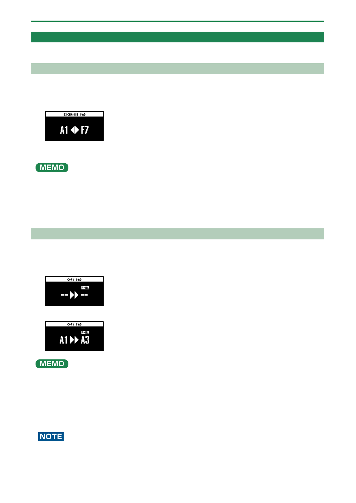
Editing a Sample (SAMPLE EDIT)
56
Organizing the Samples
This section explains the functions for making effective use of the samples.
Exchanging (Swapping) Samples Between Pads
Here’s how to exchange (swap) the samples that are assigned to two different pads.
1.
Hold down the [SHIFT] button and press the pad [5].
The EXCHANGE PAD screen appears.
2.
Press the two pads for which you want to exchange the samples.
To cancel exchanging, press the [EXIT] button.
●
To exchange a sample with a sample in a different bank, first use the bank [A/F]–[E/J] buttons to select the bank before
pressing the sample (pad) you want to exchange.
● You may notice a difference in volume when exchanging samples between different banks, due to the differences in the
BANK VOLUME parameters set for each bank.
3.
Press the [VALUE] knob or [COPY] button.
The samples for the pads are now exchanged.
Copying the Sample from a Pad
Here’s how to copy the sample that’s assigned to a pad to a different pad.
1.
Press the [COPY] button.
The COPY PAD screen appears.
2.
Press the sample (pad) you want to copy, and then the copy destination sample (pad).
If you decide to cancel copying, press the [EXIT] button.
●
To copy a sample to a different bank, first use the bank [A/F]–[E/J] buttons to select the bank before pressing the sample
(pad) for the copy destination.
● To copy a sample to a different project, first use the [CTRL 3] knob to select the project before pressing the sample (pad)
for the copy destination.
● You may notice a difference in volume when copying samples between different banks or projects, due to the differences
in the BANK VOLUME parameters set for each bank.
3.
Press the [VALUE] knob or [COPY] button.
The pad’s sample is copied.
Performing this operation overwrites (erases) the sample in the copy destination pad.
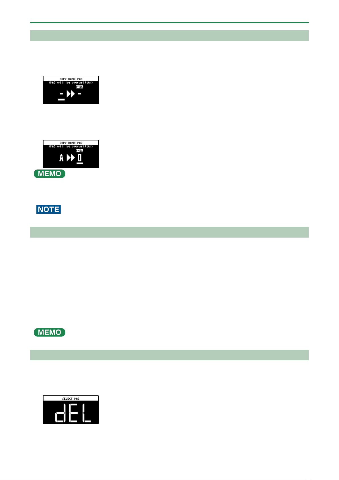
Editing a Sample (SAMPLE EDIT)
57
Copying all samples in a bank to another bank
This is how to copy all the samples in a bank to another bank.
1.
Hold down the [COPY] button and press the [EXIT] button.
The COPY BANK PAD screen appears.
2.
Press the bank [A/F]–[E/J] buttons to select the bank to copy (source).
3.
Turn the [VALUE] knob clockwise to move the cursor.
4.
Press the bank [A/F]–[E/J] buttons to select where to copy the bank (destination).
You can use the [CTRL 3] knob to select a project, when copying samples to a different project.
5.
Press the [VALUE] knob.
All the samples in the bank are copied to the specified bank.
Performing this operation overwrites (erases) the sample in the copy destination pad.
Protecting a Sample (PROTECT)
This function prevents the samples and patterns assigned to a pad from being overwritten by being copied or edited, or
accidentally deleted.
Protection is set on a bank by bank basis. Protection is set for both samples and patterns.
1.
Press the bank [A/F]–[E/J] buttons to select the banks to protect.
To select banks F–J, press the bank [A/F]–[E/J] buttons twice to make them blink.
2.
Hold down the [SHIFT] button and press the [COPY] button.
A protect confirmation message appears.
To cancel the protect operation, press the [EXIT] button.
3.
Use the [VALUE] knob to select “OK”, and press the [VALUE] knob.
To cancel protection, do the same operation again.
Deleting the Sample from a Pad
This is how to delete the sample assigned to a pad.
1.
Press the [DEL] button.
The SELECT PAD screen appears.
2.
Press the pad containing the sample you want to delete.
If you decide to cancel deleting, press the [EXIT] button.
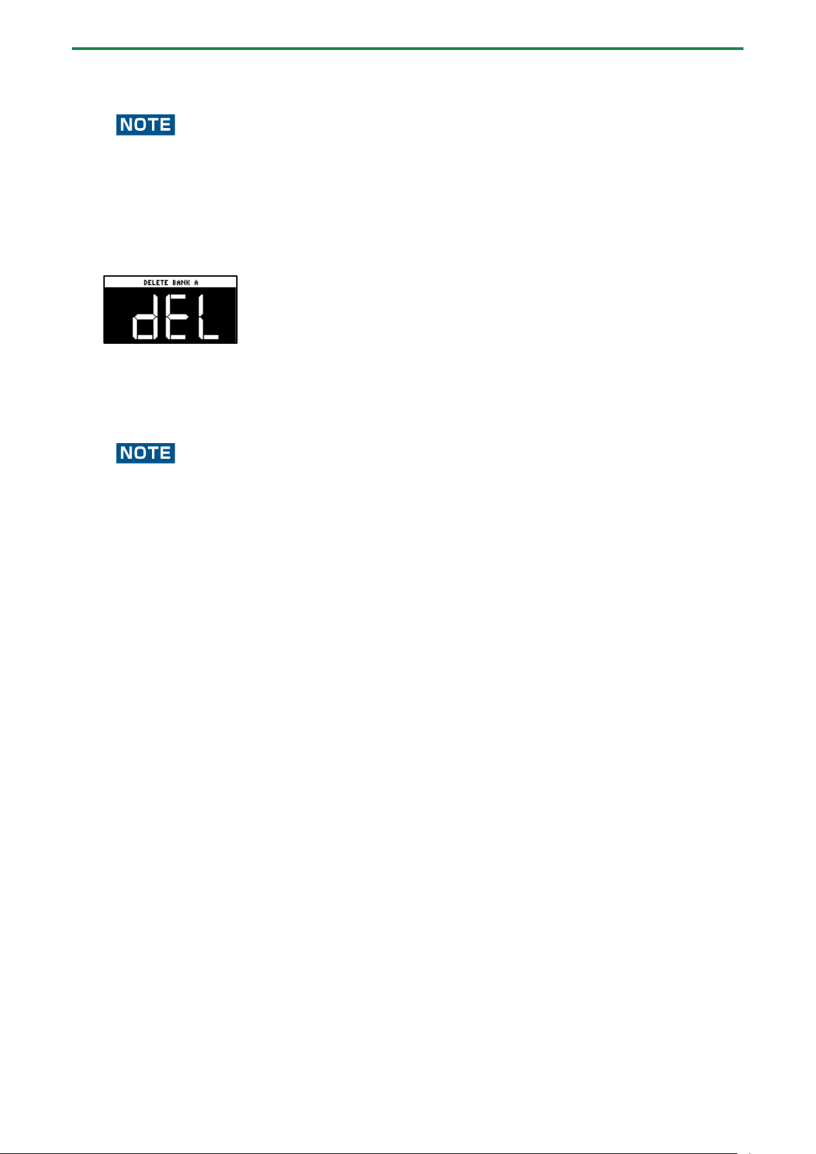
Editing a Sample (SAMPLE EDIT)
58
3.
Press the [VALUE] knob or [DEL] button.
The pad’s sample is deleted.
You can’t restore a pad’s sample after it has been deleted.
If you want to keep your data or make sure it doesn’t get accidentally modified, we recommend that you follow the steps
in “Backing up Your Data (BACKUP)(P.120)” to create regular backups.
Deleting all samples in a bank at once
1.
Hold down the [DEL] button and press the [EXIT] button.
The bank deletion screen appears.
2.
Press the bank [A/F]–[E/J] buttons.
Select a bank to delete.
3.
Press the [VALUE] knob or [DEL] button.
The samples in the selected bank are deleted.
You can’t restore a pad’s sample after it has been deleted.
If you want to keep your data or make sure it doesn’t get accidentally modified, we recommend that you follow the steps
in “Backing up Your Data (BACKUP)(P.120)” to create regular backups.
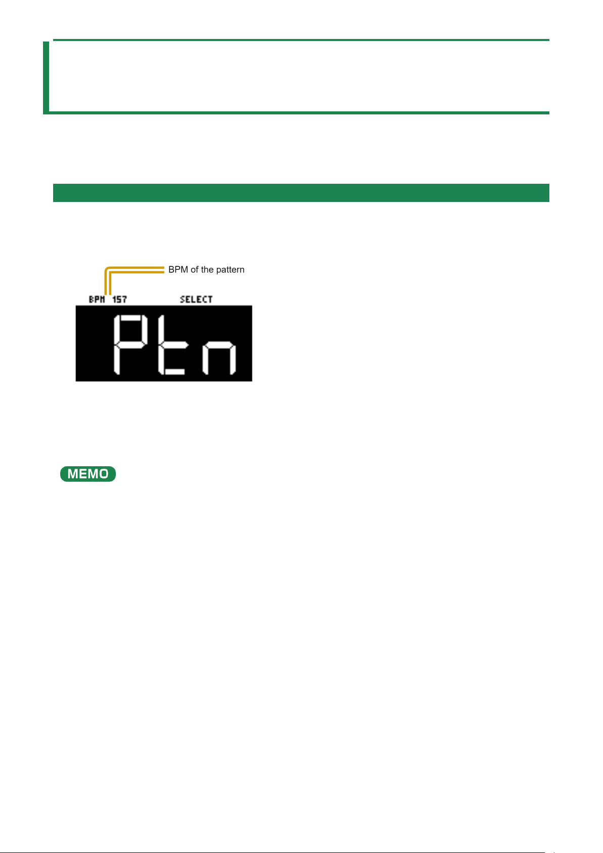
Combining Samples to Create a Pattern (PATTERN SEQUENCER)
59
Combining Samples to Create a Pattern
(PATTERN SEQUENCER)
You can record the order in which the samples play back, so that multiple samples play back at the timing you choose. The data in
which the playback order is recorded is called a “pattern”.
In this section, we explain how the patterns are played back and how to create (record) them.
Playing a Pattern
This shows you how to recall a pattern, which contains the sample playback order, and play it back.
1.
Press the [PATTERN SELECT] button.
The SELECT screen appears.
Pads to which patterns are assigned light up purple.
2.
Press pads [1]–[16].
This plays back the pattern.
When you press the other pads [1]–[16] while the pattern is playing back, this places the next pattern to play back in standby.
When the currently playing pattern has finished playing, the next pattern starts playing.
To stop the pattern playback, press the pad that’s playing back (pads [1]–[16]; lit white) or press the [EXIT] button.
●
If you hold down the [SUB PAD] button and press a [1]–[16] pad, the pattern will change immediately.
● Press pads [1]–[16] while holding down the [VALUE] knob to select a pattern (the pattern does not play back at this time).
● You can press the [REC] button while a pattern is playing back to switch to real-time pattern recording. Note that
recording starts at the top of the first measure of the pattern. If you’ve pressed the [REC] button while the pattern is
playing, the message “Wait for REC” appears.
● You can switch to pattern TR-REC by pressing the [REC] button while holding down the [SHIFT] button during pattern
playback.
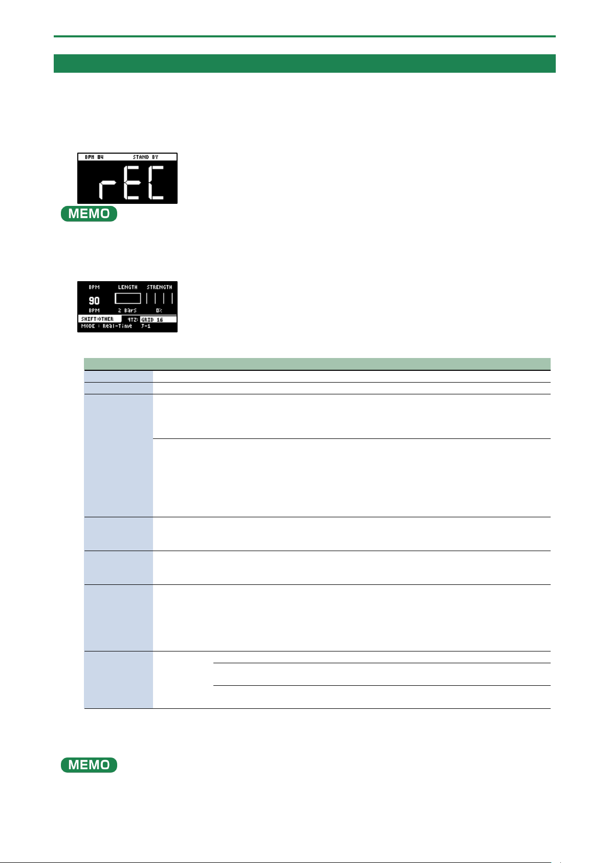
Combining Samples to Create a Pattern (PATTERN SEQUENCER)
60
Creating a New Pattern (Real-time Recording)
Here’s how to create a pattern by recording what you play on the keyboard and how you operate the controllers, just as-is.
1.
Press the [PATTERN SELECT] button.
2.
Press the [REC] button.
Empty pads in which no patterns have been recorded blink red.
The metronome sounds when the “Metronome:PTN” parameter is “ON”, which is the SYSTEM parameter “CLICK(P.124)”.
Press pad [9] while holding down the [SHIFT] button to turn the metronome sound on/off.
3.
Press pads [1]–[16] that are blinking red to select the record destination pattern.
The unit enters pattern record standby mode, and the RECORD SETTING screen appears.
4.
Configure the parameters for the pattern.
Controller
Parameter
Value
Explanation
[CTRL 1] knob
BPM
40–200
Sets the pattern’s tempo.
[CTRL 2] knob
LENGTH
1–64 (measures)
Sets the length of the pattern.
[CTRL 3] knob
STRENGTH
0–100(%)
Sets the strength of quantization used for adjusting
the note timing, as set in the QTZ parameter. When
you set this to 100%, the notes are adjusted exactly
according to the timing set in the QTZ parameter.
SHFL RATE
-50–+50
You can set how much to slide the timing of the
upbeats (the strength of the shuffle feel). A setting of
“0” results in no shuffle.
Settings in the range of +10–16 generally give a
pleasant shuffle feel.
This is enabled when the QTZ parameter is set to
“SHUFFLE 16” or “SHUFFLE 8”.
[SHIFT] button
+ [CTRL 2]
knob
TIME SIGN
1/4–7/4
Specifies the time signature.
[SHIFT] button
+ [CTRL 3]
knob
METRO VOL
0–5
Sets the volume of the metronome.
[VALUE] knob
QTZ
(QUANTIZE)
Off, GRID 32, GRID 16.3,
GRID 16, GRID 8.3, GRID 8,
GRID 4.3, GRID 4, SHUFFLE
16, SHUFFLE 8
When the player presses a pad to play back a sample,
the timing inevitably varies. Quantization is a function
that automatically corrects these inconsistencies in
timing when you record a pattern.
When quantization is set, you can record patterns in
which the notes sound within specified intervals.
[REMAIN]
button
REC MODE
Selects how the pattern sequencer records.
Real-Time
Records in real time.
The [REMAIN] button lights up at this time.
TR-REC
Records using TR-REC.
The [REMAIN] button blinks at this time.
5.
Press the [REC] button.
The pattern is recorded. The pattern repeatedly records at the length specified in the LENGTH parameter (loop recording).
You can record and overdub different and multiple samples, without overwriting the pattern.
●
While you’re recording a pattern, the unit switches between rehearsal and recording mode each time you press the [REC]
button. When in rehearsal mode, loop playback continues for the recorded pattern without being recorded. This function
is useful when you want to practice recording a pattern.
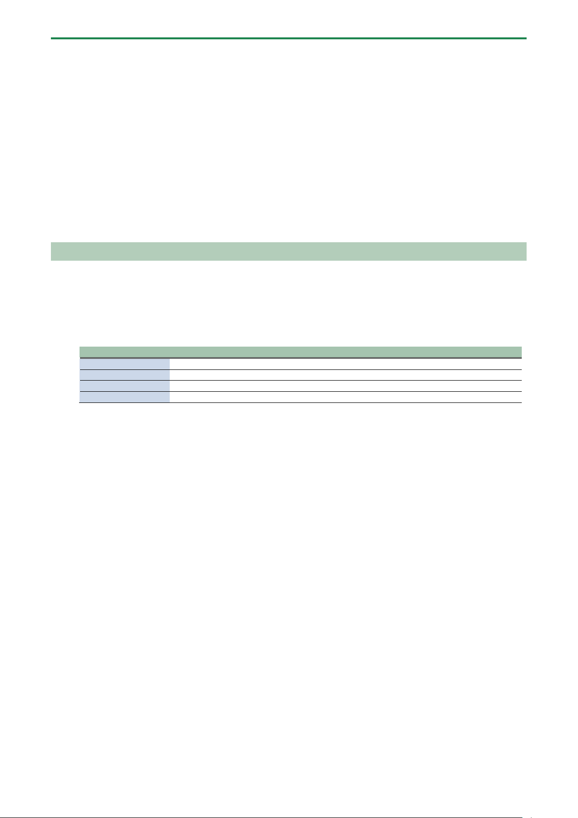
Combining Samples to Create a Pattern (PATTERN SEQUENCER)
61
●
You can press the [REC] button while a pattern is playing back to switch to pattern recording. Note that recording starts at
the beginning of the pattern. If you’ve pressed the [REC] button in the middle of the pattern, the message “Wait for REC”
appears.
● While the pattern is recording, press the [PATTERN SELECT] button while holding down the [SHIFT] button to undo the
data you just inputted (recorded). This is useful when you made a mistake in timing when recording a pattern.
● If you press the [RECORD SETTING] button while the pattern is recording or during rehearsal mode, the RECORD SETTING
screen is shown. Note that you can’t set the LENGTH parameter at this time. Set the LENGTH parameter before recording a
pattern. Press the [EXIT] button to return to the previous screen.
● Press the [DEL] button while recording a pattern to enter erase mode (which lets erase a pattern). The performance data
recorded in the pattern for the pads (samples) [1]–[16] is erased, during the time range that you hold them down. Press
the [DEL] button again to return to the previous screen.
● You can also record note messages that are input via the MIDI IN connector and the USB port to a pattern.
6.
When you are finished recording the pattern, press the [EXIT] button twice.
Press the [EXIT] button once to finish recording. The recorded pattern is automatically saved to the pad. Press twice to stop
pattern playback.
Adding a Count-in Before Recording a Pattern
This feature adds a count-in before the pattern start recording. This gives you time to get ready to play before the pattern actually
begins recording.
1.
Hold down the [SHIFT] button and press the pad [10].
Edit the count-in setting.
Value
Explanation
COUNTIN 1MEAS
Adds a one-measure count-in before recording.
COUNTIN 2MEAS
Adds a two-measure count-in before recording.
COUNTIN WAIT
Recording starts along with sample playback.
COUNTIN OFF
No count-in is used. Press the [REC] button to immediately begin recording.
The value changes in order each time you press pad [10] while holding down the [SHIFT] button.
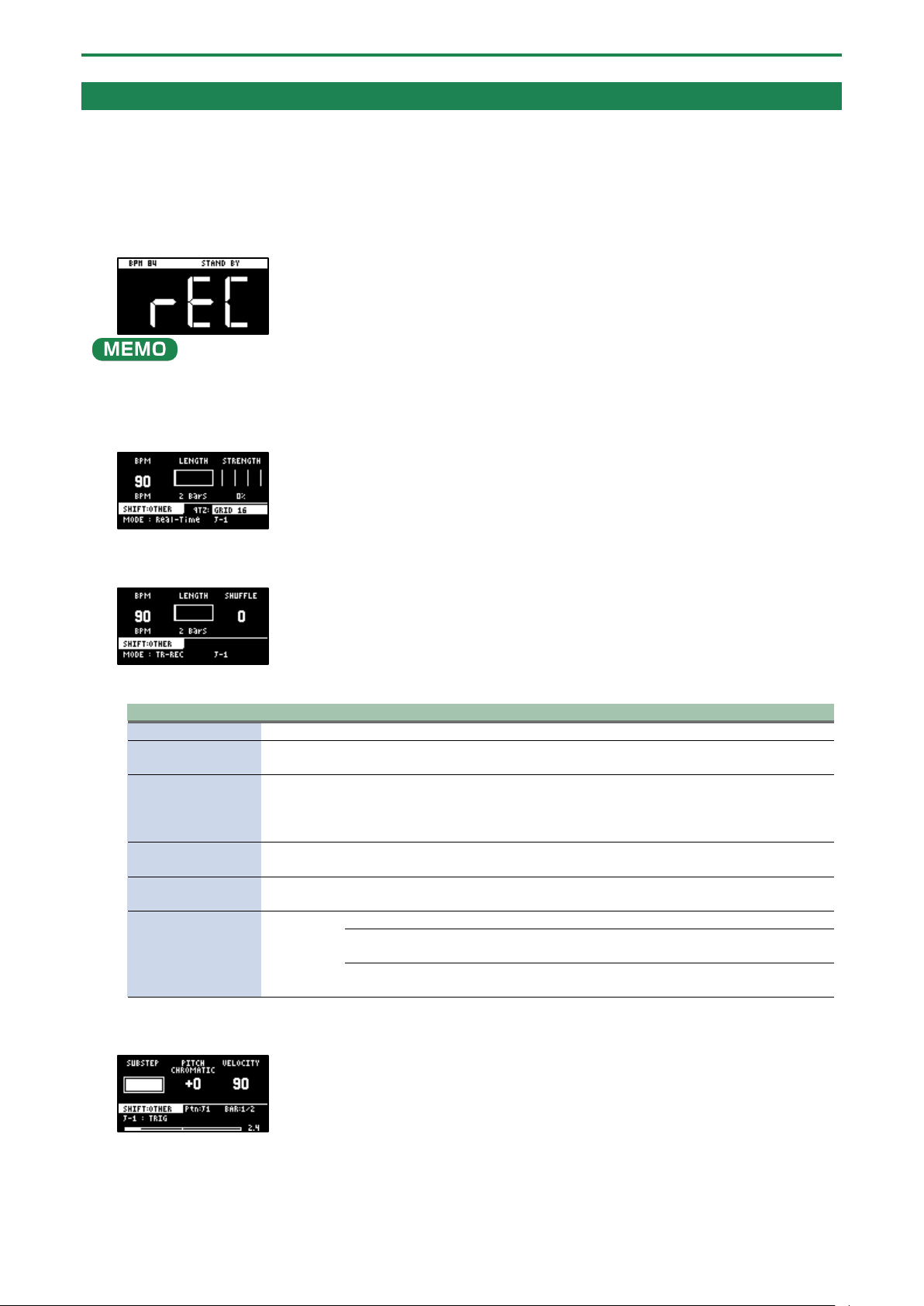
Combining Samples to Create a Pattern (PATTERN SEQUENCER)
62
Creating a New Pattern (TR-REC)
Here’s how to create a pattern by setting the sample playback timing at the position you like on the steps.
This method of recording is suitable for creating drum patterns.
1.
Press the [PATTERN SELECT] button.
2.
Press the [REC] button.
Empty pads in which no patterns have been recorded blink red.
The metronome sounds when the “Metronome:PTN” parameter is “ON” (the SYSTEM parameter “CLICK(P.124)”).
Press pad [9] while holding down the [SHIFT] button to turn the metronome sound on/off.
3.
Press pads [1]–[16] that are blinking red to select the record destination pattern.
The unit enters pattern record standby mode, and the RECORD SETTING screen appears.
4.
Press the [REMAIN] button.
The pattern recording method switches to “TR-REC”.
5.
Set the parameters for the pattern.
Controller
Parameter
Value
Explanation
[CTRL 1] knob
BPM
40–200
Sets the pattern’s tempo.
[CTRL 2] knob
LENGTH
1–64
(measures)
Sets the length of the pattern.
[CTRL 3] knob
SHFL RATE
-50–+50
You can set how much to slide the timing of the upbeats (the
strength of the shuffle feel). A setting of “0” results in no shuffle.
Settings in the range of +10–16 generally give a pleasant shuffle
feel.
[SHIFT] button +
[CTRL 2] knob
TIME
SIGN
1/4–7/4
Specifies the time signature.
[SHIFT] button +
[CTRL 3] knob
METRO
VOL
0–5
Sets the volume of the metronome.
[REMAIN] button
REC MODE
Selects how the pattern sequencer records.
Real-Time
Records in real time.
The [REMAIN] button lights up at this time.
TR-REC
Records using TR-REC.
The [REMAIN] button blinks at this time.
6.
Press the [REC] button.
TR-REC pattern recording begins.
7.
Press pads [1]–[16] while holding down the [SUB PAD] button to select the sample.
8.
Set the parameters for the sample to input.
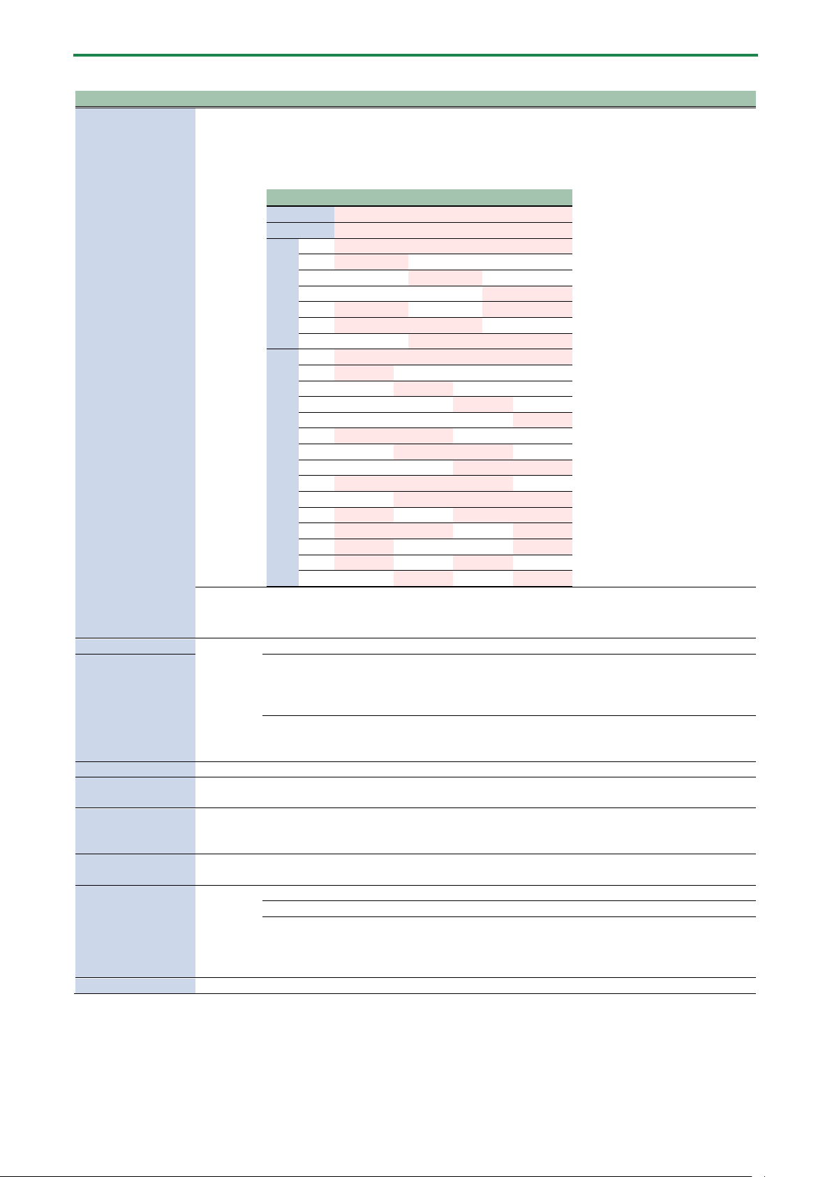
Combining Samples to Create a Pattern (PATTERN SEQUENCER)
63
Controller
Parameter
Value
Explanation
[CTRL 1] knob
SUBSTEP
You can split up the steps into multiple and separate units (sub steps).
You can also configure how the split sub steps are played.
* This is enabled when MODE is “TRIG”.
Value
Pattern
1
ON
2
ON
ON
3
a
ON
ON
ON
b
ON
c
ON
d
ON
e
ON
ON
f
ON
ON
g
ON
ON
4
a
ON
ON
ON
ON
b
ON
c
ON
d
ON
e
ON
f
ON
ON
g
ON
ON
h
ON
ON
i
ON
ON
ON
j
ON
ON
ON
k
ON
ON
ON
l
ON
ON
ON
m
ON
ON
n
ON
ON
o
ON
ON
HOLD
STEP
1–32, LAST
Sets the step length used for sample playback.
* This is enabled when MODE is “HOLD STEP”.
[CTRL 2] knob
PITCH
-12–+12
Sets the sample pitch.
[PITCH/SPEED]
button
CHROMATIC
Set and input the sample’s pitch for each step in this mode.
Each step that’s input can be played back at a different pitch.
You can press the [VALUE] knob in this mode to select the scale.
Hold down and turn the [VALUE] knob to select a note from the scale.
PAD
The sample’s pitch is input as a fixed pitch in this mode.
With this setting, all of the steps you input play back at the pitch you set in
PITCH.
[CTRL 3] knob
VELOCITY
0–127
Specifies the dynamics (velocity) of the sample.
[SHIFT] button +
[CTRL 1] knob
BPM
40–200
Sets the pattern’s tempo.
[SHIFT] button +
[CTRL 2] knob
SHUFFLE
-50–+50
You can set how much to slide the timing of the upbeats (the strength of the
shuffle feel). A setting of “0” results in no shuffle.
Settings in the range of +10–16 generally give a pleasant shuffle feel.
[SHIFT] button +
[CTRL 3] knob
START
-50–99 (%)
Sets the timing at which the sample starts playing back.
If this is set to a value other than 0%, sub steps cannot be set.
[REMAIN] button
MODE
This selects the input mode for TR-REC.
TRIG
The sample plays in each step.
HOLD STEP
The steps play back joined at the length specified by the [CTRL 1] knob.
Joining two steps gives the same results as using a tie.
When MODE is set to “HOLD STEP”, the GATE parameter for the sample is
automatically set to “ON”.
[HOLD] button
-
-
Plays back only the selected pad.
9.
Press pads [1]–[16] to select the step (timing) at which the sample plays back.
The sample is placed (input) into the step you selected using pads [1]–[16].
The pads light up corresponding to the steps that sound.
Press pads [1]–[16] to turn off the pads corresponding to the steps you don’t want to sound.
10.
To input patterns from measure 2 onward, use the [VALUE] knob to select the measure (bar).
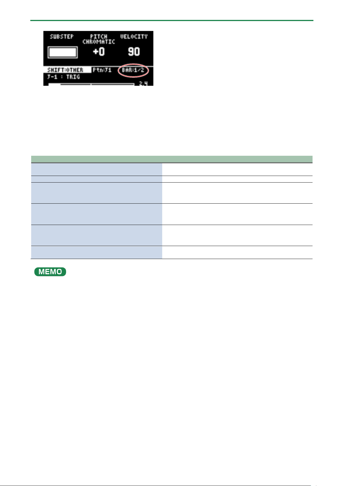
Combining Samples to Create a Pattern (PATTERN SEQUENCER)
64
11.
When you are finished recording the pattern, press the [EXIT] button twice.
Press the [EXIT] button once to finish recording. The recorded pattern is automatically saved to the pad.
Press twice to stop pattern playback.
Functions you can use during TR-REC input
You can use the controllers in combination during TR-REC input to perform the following operations.
Controller
Explanation
[DEL] button + [A/F] button
Deletes the notes (for one measure) corresponding to the selected
pad.
[DEL] button + [B/G] button
Deletes the notes (for one measure) corresponding to all pads.
[ROLL] button + [CTRL 1] knob
You can record the motion of [CTRL 1] knob in the steps.
* This is enabled when MODE is “TRIG”.
[ROLL] button + [CTRL 2] knob
You can record the motion of [CTRL 2] knob in the steps.
* This is enabled when MODE is “TRIG”.
[ROLL] button + [CTRL 3] knob
You can record the motion of [CTRL 3] knob in the steps.
* This is enabled when MODE is “TRIG”.
[VALUE] knob (hold down) + [SUB PAD] button + pads [1]–
[16]
You can select samples without playing them back.
●
If you press the [RECORD SETTING] button while the pattern is recording, the RECORD SETTING screen is shown. Note that
you can’t set the LENGTH or TIME SIGN parameters at this time. These parameters need to be edited before you record the
pattern.
● Press the [EXIT] button to return to the previous screen.
● You can switch to pattern TR-REC by pressing the [REC] button while holding down the [SHIFT] button during pattern
playback.
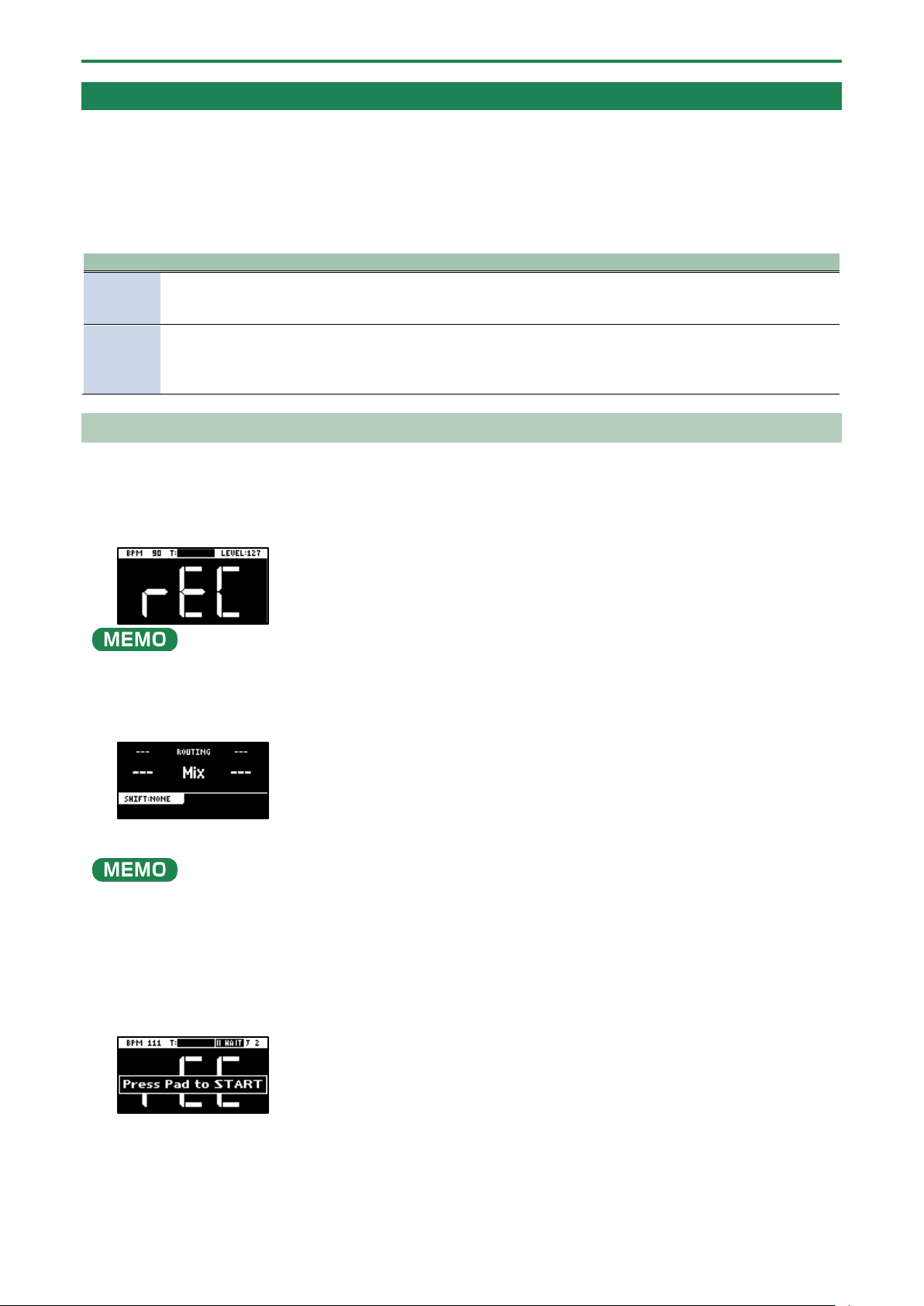
Combining Samples to Create a Pattern (PATTERN SEQUENCER)
65
Converting Patterns to Samples
Here’s how to convert a performance that’s recorded in a pattern into a sample.
There are two ways to convert performance data to a sample, each with their own characteristics.
Differences between bouncing and resampling
Type
How each type works differently
Bouncing
Converts the entire selected pattern into a sample. No sound is heard while the sample is being converted. The
pattern is converted into a sample without applying effects.
→
“Converting Patterns to Samples(P.65)”
Resampling
The selected pattern plays back once it is converted into a sample. You can stop the conversion at a point you like
while listening to the sound.
With resampling, you can convert the pattern with effects applied.
→
“Sampling a Pattern (RESAMPLE)(P.65)”
Sampling a Pattern (RESAMPLE)
You can sample the performance you recorded to a pattern as-is, and turn it into a sample.
1.
Press the [PATTERN SELECT] button.
2.
Press the [RESAMPLE] button.
The metronome sounds when the “Metronome:REC” parameter is “ON” (the SYSTEM parameter “CLICK(P.124)”).
Press pad [9] while holding down the [SHIFT] button to turn the metronome sound on/off.
3.
Press the [RECORD SETTING] button.
The input settings screen appears.
4.
Use the [CTRL 2] knob to set ROUTING to “Mix.”
When ROUTING is set to “ExtIn,” only the audio input from an external device is sampled (the sample’s audio is not included in
the resample). You can sample your performance while playing back samples as backing sounds.
5.
Press the [EXIT] button.
6.
Press the pads [1]–[16] that are blinking red.
Empty pads to which samples haven’t been assigned blink red.
When you press an empty pad, the message “Press Pad to START” is shown. Pads that contain a recorded pattern blink in
blue.
7.
Press pads [1]–[16] to select a pattern.
Sampling begins when the pattern starts playing back.
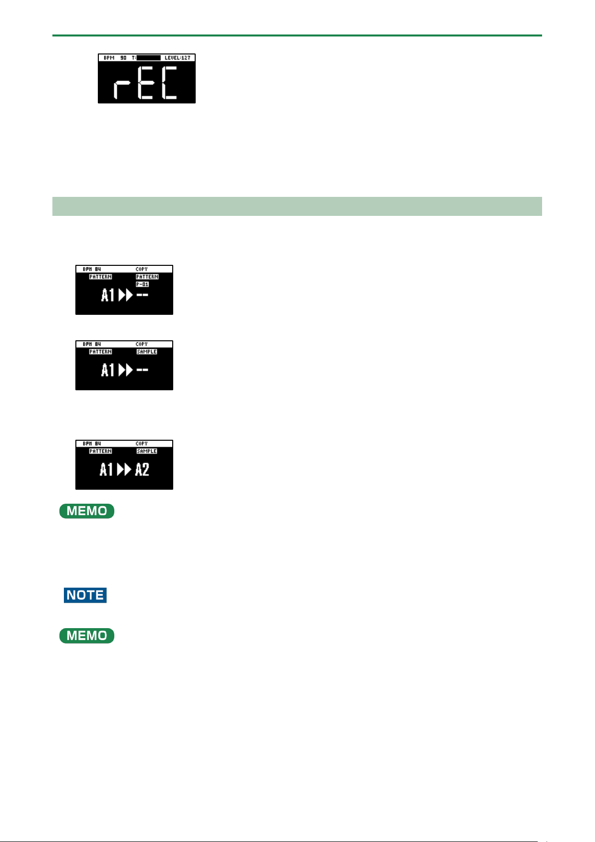
Combining Samples to Create a Pattern (PATTERN SEQUENCER)
66
If you decide to cancel sampling, press the [EXIT] button.
8.
To exit sampling, press the [REC] button again.
“Bouncing” is another method you can use to convert a pattern into a sample.
For details, refer to “Converting Patterns to Samples (BOUNCE)(P.66).”
Converting Patterns to Samples (BOUNCE)
Here’s how to convert a pattern that’s assigned to a pad into a sample, and then assign that sample to a pad.
1.
Follow the steps in “Copying the Pattern of a Pad(P.78)” to select the pattern you want to convert.
2.
Press the [PATTERN SELECT] button.
If a sample is already saved to a pad, the pad lights up dimly in blue.
Empty pads blink blue.
3.
Press the pad where you want to save the converted sample.
If you decide to cancel the conversion to a sample, press the [EXIT] button.
If you use the bank [A/F]–[E/J] buttons to select the bank before pressing the save destination pad, you can assign the sample
to a pad in a different bank.
Also, you can use the [CTRL 3] knob to select a project, when assigning the sample to a pad belonging to a different project.
4.
Press the [VALUE] knob or [COPY] button.
The pattern is converted to a sample and assigned to the specified pad.
This overwrites (erases) the sample in the save destination pad.
When a pattern is converted into a sample, the effect (BUS 1–4) is automatically turned off (bypassed).
Converting data for longer patterns into samples may take some time.
You can also use resampling to convert patterns into samples.
For details, refer to “Sampling a Pattern (RESAMPLE)(P.65).”

Combining Samples to Create a Pattern (PATTERN SEQUENCER)
67
Selecting a Pattern Bank
Select the bank to use from the 10 available banks (A–J).
1.
Press the bank [A/F]–[E/J] buttons.
The bank switches.
Each time you press the bank [A/F] button, the bank switches between A and F.
When bank A–E is selected, the bank [A/F]–[E/J] button lights up. When bank F–J is selected, the bank [A/F]–[E/J] button
blinks.
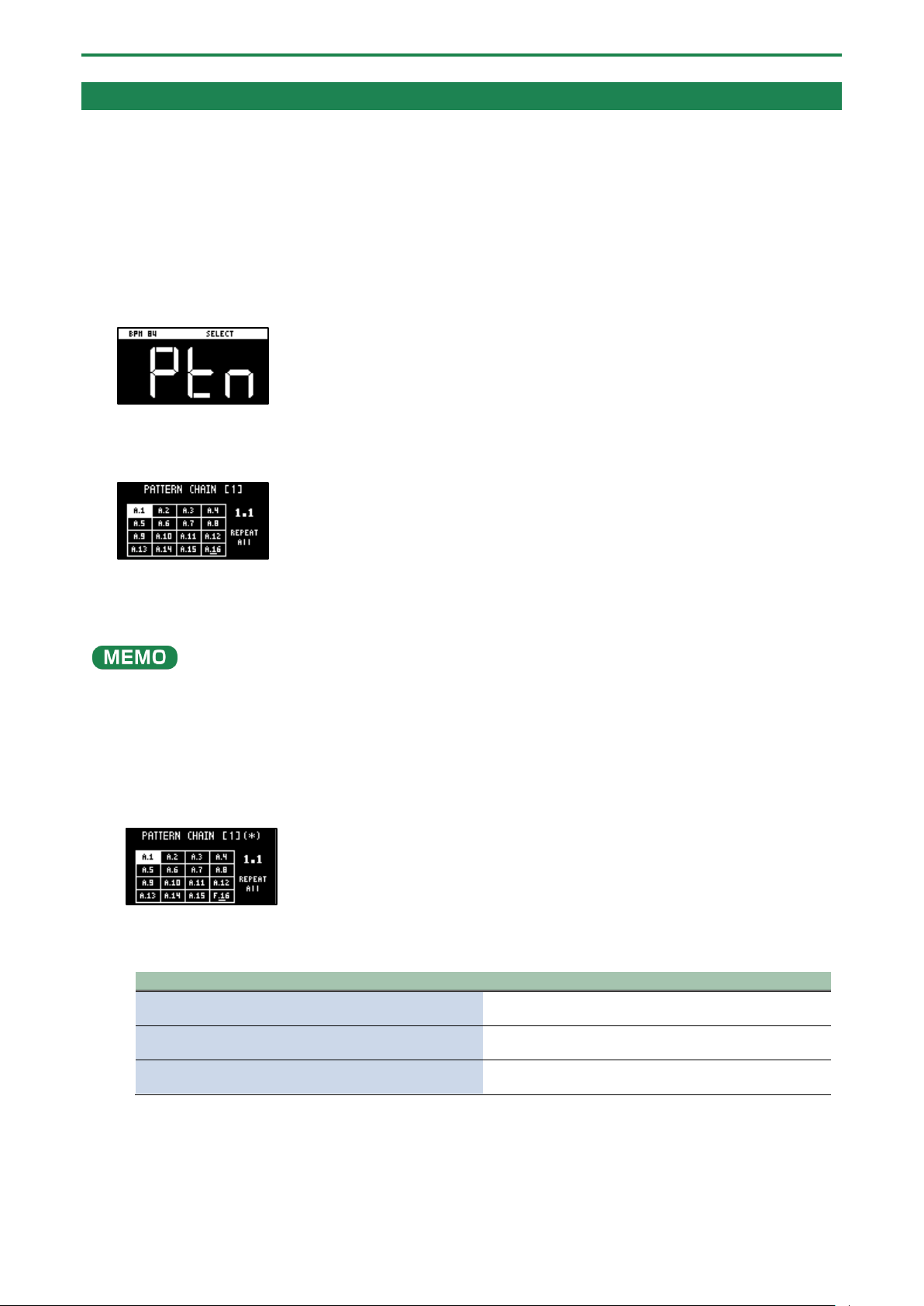
Combining Samples to Create a Pattern (PATTERN SEQUENCER)
68
Playing Back Patterns in Order (PATTERN CHAIN)
Pattern chain is a function that lets you play back patterns you’ve created with the pattern sequencer, in a specified order.
You can record and play back up to 16 patterns with a single pattern chain. Up to 16 pattern chains can be stored per project.
Creating a pattern chain
1.
Use the pattern sequencer to create patterns beforehand (Creating a New Pattern (Real-time
Recording)
(P.60), Creating a New Pattern (TR-REC)(P.62)).
2.
Press the [PATTERN SELECT] button.
The unit enters pattern sequencer mode.
3.
While holding down the [HOLD] button, press pads [1]–[16] to select the pattern chain number (1–16) to
record.
The PATTERN CHAIN screen appears.
4.
Press pads [1]–[16] to select the pattern you want to record to the pattern chain.
5.
When you finish recording to the pattern chain, press the [EXIT] button.
The unit returns to the PATTERN SELECT screen. and the recorded pattern chain is automatically saved.
● You can also record patterns that are in different banks to a pattern chain. To switch between banks, press the bank [A/F]–
[E/J] buttons.
● Turn the [VALUE] knob to move the cursor. You can insert a pattern at the cursor position.
● To delete the pattern at the cursor position, press the [DEL] button.
● Once you’ve edited the pattern chain, an asterisk (*) appears at the top right-hand part of the screen. If you want to revert
(undo) your edits, press the [DEL] button while holding down the [SHIFT] button.
● Press the [REMAIN] button to set the pattern chain to play back repeatedly. Toggle the repeat playback setting on/off by
pressing the [REMAIN] button.
Value
Explanation
REPEAT All
Plays back repeatedly from the beginning of the pattern
chain to the end.
REPEAT Current
Plays the current pattern (patterns with pads that are lit
up pink) back repeatedly.
REPEAT Off
Plays the pattern chain back only one time, from
beginning to end. Playback does not repeat.
Playing back a pattern chain
1.
Press the [PATTERN SELECT] button.
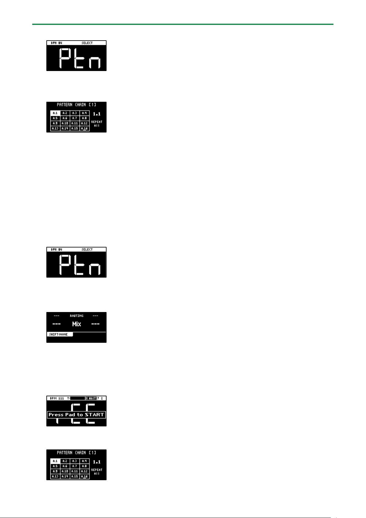
Combining Samples to Create a Pattern (PATTERN SEQUENCER)
69
The unit enters pattern sequencer mode.
2.
While holding down the [HOLD] button, press pads [1]–[16] to select the pattern chain number to play
back.
The PATTERN CHAIN screen appears.
3.
Press the [SUB PAD] button.
The selected pattern chain plays back.
To stop playback, press the [SUB PAD] button again.
4.
To exit pattern chain, press the [EXIT] button.
The unit returns to the PATTERN SELECT screen.
Sampling the playback of a pattern chain
You can sample (resample) the audio of a pattern chain as it plays back.
1.
Press the [PATTERN SELECT] button.
The unit enters pattern sequencer mode.
2.
Press the [RESAMPLE] button.
3.
Press the [RECORD SETTING] button.
The input settings screen appears.
4.
Use the [CTRL 2] knob to set ROUTING to “Mix”.
5.
Press the [EXIT] button.
6.
Press the pads [1]–[16] that are blinking red.
Empty pads to which samples haven’t been assigned blink red.
When you press an empty pad, the pad changes to blinking purple, and a message “Press Pad to START” is shown.
7.
Press pads [1]–[16] while holding down the [HOLD] button to select the pattern chain to play back.
The PATTERN CHAIN screen appears.

Combining Samples to Create a Pattern (PATTERN SEQUENCER)
70
8.
Press the [SUB PAD] button.
Sampling begins when the selected pattern chain starts playing back.
If you decide to cancel sampling, press the [EXIT] button.
When pattern chain repeat is set to “REPEAT Off”, sampling ends at the same time as pattern chain playback ends.
9.
To exit sampling, press the [REC] button.
The sample is saved to the pad.
Combining Samples to Create a Pattern (PATTERN SEQUENCER)
71
Recording Effect Operations to a Pattern (EFX MOTION REC)
Here’s how to record your effect on/off and effect parameter ([CTRL 1]–[CTRL 3] knob) operations to a pattern in real time.
1.
Press the [PATTERN SELECT] button.
Pads to which patterns are assigned light up purple.
2.
Press pads [1]–[16] to select the pattern to which you want to record the effect operations.
This plays back the pattern.
3.
Press the [REC] button.
The pattern begins recording in real time.
4.
Press the [MARK] button.
The message “MOTION REC START” is shown (EFX MOTION REC).
The effect operations now begin recording.
5.
Operate the effects along with the pattern performance.
Your effect operations are recorded to the pattern.
6.
Once you finish recording, press the [EXIT] button.
The same effect operations you made when recording are played back along with the pattern (EFX MOTION PLAY).
Use the [START/END] button to enable/disable playback of the effect operations you recorded.
[START/END] button
Action
Blinks
EFX MOTION PLAY is ON.
The recorded effect operations are played back.
Unlit
EFX MOTION PLAY is OFF.
The recorded effect operations do not play back.

Combining Samples to Create a Pattern (PATTERN SEQUENCER)
72
Deleting Effect Operations Recorded in a Pattern (EFX MOTION ERASE)
Here’s how to delete effect operations that you recorded using the steps shown in “Recording Effect Operations to a Pattern (EFX
MOTION REC)(P.71)” from a pattern.
1.
Press the [PATTERN SELECT] button.
2.
Press the [PATTERN EDIT] button.
3.
Press pads [1]–[16] to select the pattern you want to edit.
The pattern edit screen appears.
4.
Hold down the [DEL] button and press the [MARK] button.
The “Operation Completed!” message appears.
The effect operations are now deleted.
Deleting Specific Effect Operations From a Pattern
This shows how to delete specific effect operations that you recorded using the steps shown in “Recording Effect Operations to a
Pattern (EFX MOTION REC)(P.71)” from a pattern.
1.
Press the [PATTERN SELECT] button.
Pads to which patterns are assigned light up purple.
2.
Press pads [1]–[16] to select the pattern from which you want to delete the effect operations.
This plays back the pattern.
3.
Press the [REC] button.
The pattern begins recording in real time.
4.
Listen to the pattern. When the part for which you want to delete the effect operations plays, press the
[MARK] button while holding down the [SHIFT] button.
The “MOTION ERASE ON” message appears.
This begins deleting the effect operations.
5.
When the pattern reaches the point at which you want to stop deleting the effect operations, press the
[MARK] button while holding down the [SHIFT] button.
The “MOTION ERASE OFF” message appears.
This deletes the effect operations within the range between the “MOTION ERASE ON” and “MOTION ERASE OFF” messages.
6.
When you’re finished deleting, press the [EXIT] button.

Combining Samples to Create a Pattern (PATTERN SEQUENCER)
73
Recording Pad Mute Operations to a Pattern (PAD MUTE MOTION REC)
Here’s how to record the pad mute on/off operations to a pattern in real time.
1.
Press the [PATTERN SELECT] button.
Pads to which patterns are assigned light up purple.
2.
Press pads [1]–[16] to select the pattern to which you want to record the pad mute operations.
This plays back the pattern.
3.
Press the [REC] button.
The pattern begins recording in real time.
4.
Hold down the [SHIFT] button and press the [REVERSE] and [REMAIN] buttons.
The message “PAD MUTE MODE (MOTION REC)” appears (PAD MUTE MOTION REC).
The pad mute operations now begin recording.
5.
While listening to the pattern, press the pads [1]–[16] of the samples you want to mute. Press pads [1]–
[16] again when you want to unmute the samples.
The pad mute operations are recorded to the pattern.
Muted samples (pads) are lit up red, and unmuted samples (pads) are lit up white.
6.
Once you finish recording, press the [EXIT] button.
The pad mute operations you recorded are played back along with the pattern (PAD MUTE MOTION PLAY).
7.
To exit the pad mute playback, press the [EXIT] button.
The unit now returns to playing the patterns normally.
At this time, the pad mute is not played back, but the pad mute operations are stored in memory.

Combining Samples to Create a Pattern (PATTERN SEQUENCER)
74
Deleting Pad Mute Operations Recorded in a Pattern (PAD MUTE MOTION ERASE)
Here’s how to delete pad mute operations that you recorded using the steps shown in “Recording Effect Operations to a Pattern
(EFX MOTION REC)(P.71)” from a pattern.
1.
Press the [PATTERN SELECT] button.
2.
Press the [PATTERN EDIT] button.
3.
Press pads [1]–[16] to select the pattern you want to edit.
The pattern edit screen appears.
4.
Hold down the [DEL] button and press the [REVERSE] button.
The “Operation Completed!” message appears.
The pad mute operations are now deleted.
Deleting Specific Pad Mute Operations from a Pattern
This shows how to delete specific pad mute operations that you recorded using the steps shown in “Recording Pad Mute
Operations to a Pattern (PAD MUTE MOTION REC)(P.73)” from a pattern.
1.
Press the [PATTERN SELECT] button.
Pads to which patterns are assigned light up purple.
2.
Press pads [1]–[16] to select the pattern from which you want to delete the pad mute operations.
This plays back the pattern.
3.
Press the [REC] button.
The pattern begins recording in real time.
4.
Hold down the [SHIFT] button and press the [REVERSE] and [REMAIN] buttons.
The message “PAD MUTE MODE (Motion REC)” appears (PAD MUTE MOTION REC).
The pad mute operations now begin recording.
5.
Press the [DEL] button.
The message “PAD MUTE MODE (Motion ERASE)” appears (PAD MUTE MOTION ERASE).
Now you can delete the pad mute operations.
The pads light up blue.
6.
Listen to the pattern. When the part for which you want to delete the pad mute operations plays, press
the pads [1]–[16] (the pads with the pad mute operations you want to delete).
The pad mute operations recorded for that pad are deleted while you hold down the pad.
7.
When you’ve finished deleting, press the [DEL] button.
The message “PAD MUTE MODE (MOTION REC)” appears.
The unit returns to recording pad mute operations (PAD MUTE MOTION REC).

Combining Samples to Create a Pattern (PATTERN SEQUENCER)
75
Editing a Pattern (PATTERN EDIT)
You can change the length of a pattern or change the range within which it plays back.
You can also copy and chain patterns, and delete unwanted sections of a pattern.
1.
Press the [PATTERN SELECT] button.
2.
Press the [PATTERN EDIT] button.
3.
Press pads [1]–[16] to select the pattern you want to edit.
The pattern edit screen appears.
4.
Use the [CTRL 1]–[CTRL 3] knobs to edit the parameters.
Controller
Parameter
Value
Explanation
[CTRL 1]
knob
BPM
40–200
Sets the pattern’s tempo.
[CTRL 2]
knob
LOOP
START
1–64 (measures)
Sets the measure at which the pattern begins playing back.
● This is enabled when the length (number of measures) set in
the LENGTH parameter is shorter than the overall pattern.
[CTRL 3]
knob
LENGTH
1, 2, 4, 8, 16, 32, 64
(measures)
Sets the length of pattern playback.
You can select patterns to delete that are within the loop range (the playback range).
Use the following operation in continuation from step 4.
1.
When you hold down the [DEL] button, the pads (patterns) within the loop range light up blue.
2.
While pressing the [DEL] button, press the pad (pattern) you want to delete.
The selected pad (pattern) lights up bright blue.
3.
While holding down the [DEL] button, press the [VALUE] knob.
The selected pad (pattern) is deleted.
Copying and Connecting Patterns (DUPLICATE)
This shows how to copy a pattern and connect it to the current pattern. By doing this, the overall pattern becomes twice as long.
1.
Press the [PATTERN SELECT] button.
2.
Press the [PATTERN EDIT] button.
3.
Press pads [1]–[16] to select the pattern you want to edit.
The pattern edit screen appears.
4.
Press the [VALUE] knob.
A menu appears.
5.
Use the [VALUE] knob to select “DUPLICATE”, and press the [VALUE] knob.
The pattern is copied and connected to the end of the current pattern.
Cropping Unnecessary Sections from a Pattern (CROP)
This deletes all the sections from a pattern except for the range you select.
1.
Press the [PATTERN SELECT] button.
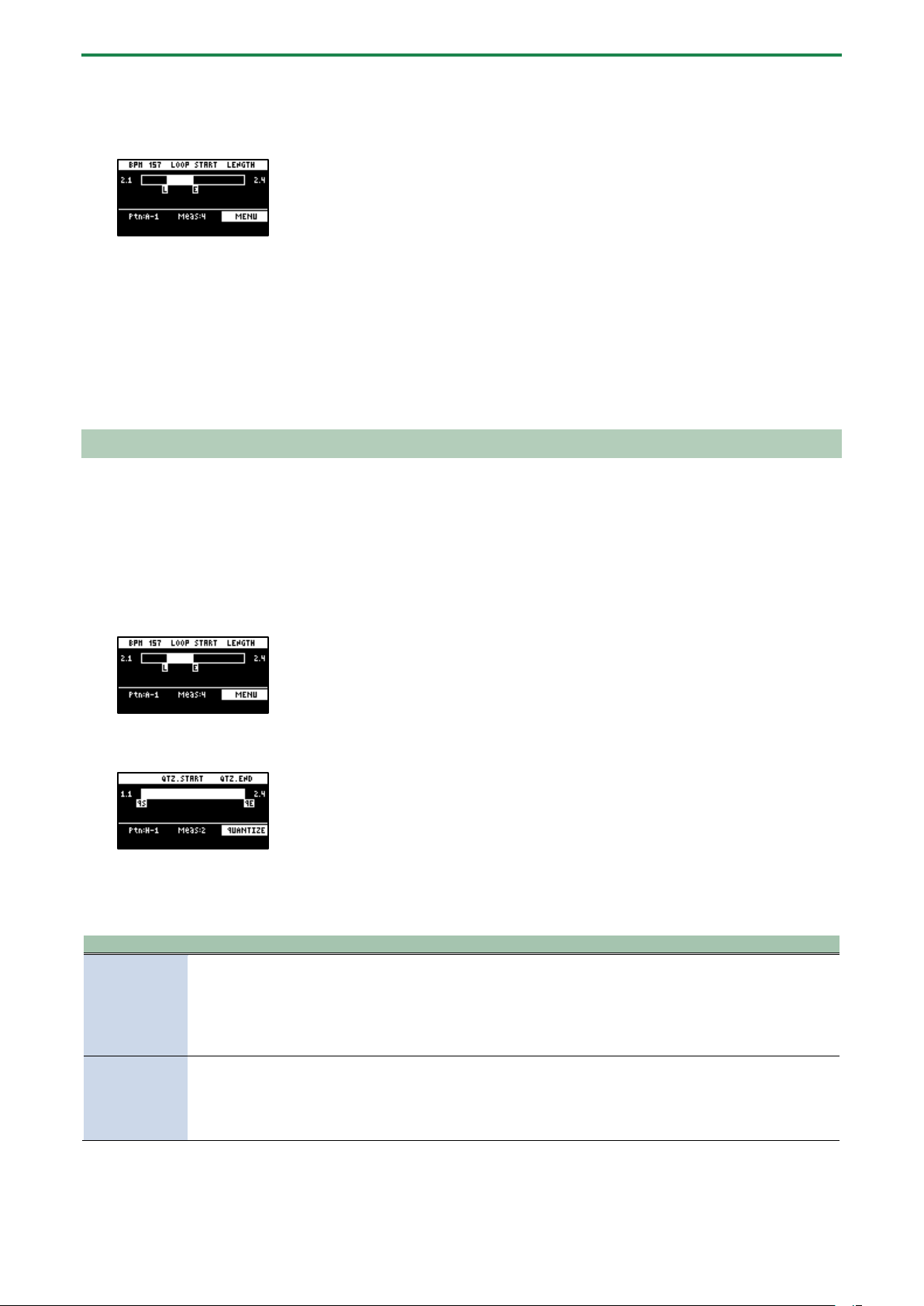
Combining Samples to Create a Pattern (PATTERN SEQUENCER)
76
2.
Press the [PATTERN EDIT] button.
3.
Press pads [1]–[16] to select the pattern you want to edit.
The pattern edit screen appears.
4.
Set the range you want to keep within the pattern in the LOOP START and LENGTH parameters (“Editing
a Pattern (PATTERN EDIT)(P.75)”).
5.
Press the [VALUE] knob.
A menu appears.
6.
Use the [VALUE] knob to select “CROP”, and press the [VALUE] knob.
All sections of the pattern outside of the playback range (the length selected with the LOOP START and LENGTH parameters)
are deleted.
Aligning the Playback Timing of Samples Inputted to a Pattern (QUANTIZE)
You can quantize the notes of a pattern that you’ve inputted in real time.
This lets you correct patterns in which the beginning of the sample playback is out of time with the beat of the song.
1.
Press the [PATTERN SELECT] button.
2.
Press the [PATTERN EDIT] button.
3.
Press pads [1]–[16] to select the pattern you want to quantize.
The pattern edit screen appears.
4.
Press the [RECORD SETTING] button.
The quantize screen appears.
If the quantize screen isn’t shown, press the [RECORD SETTING] button once more.
5.
Press pads [1]–[16] to select the samples you want to quantize.
6.
Use the [CTRL 1]–[CTRL 3] knobs to configure the quantize parameters.
Controller
Parameter
Value
Explanation
[CTRL 2] knob
QTZ
GRID 32, GRID 16.3, GRID 16,
GRID 8.3, GRID 8, GRID 4.3,
GRID 4, SHUFFLE 16, SHUFFLE
8
Specifies the interval to which the notes should be aligned.
Set this to “GRID 32” when quantizing to thirty-second note
intervals, and set this to “GRID 4.3” when quantizing to quarter-
note triplets.
The “SHUFFLE 16” and “SHUFFLE 8” settings give the rhythm a
shuffle or swing feel.
[CTRL 3] knob
STR
0–100 (%)
Sets the strength of quantization used for adjusting the note
timing, as set in the QTZ parameter.
If you’ve selected “GRID” for the QTZ parameter, a setting of
100% corrects the note timing to match the timing set in the
QTZ parameter.
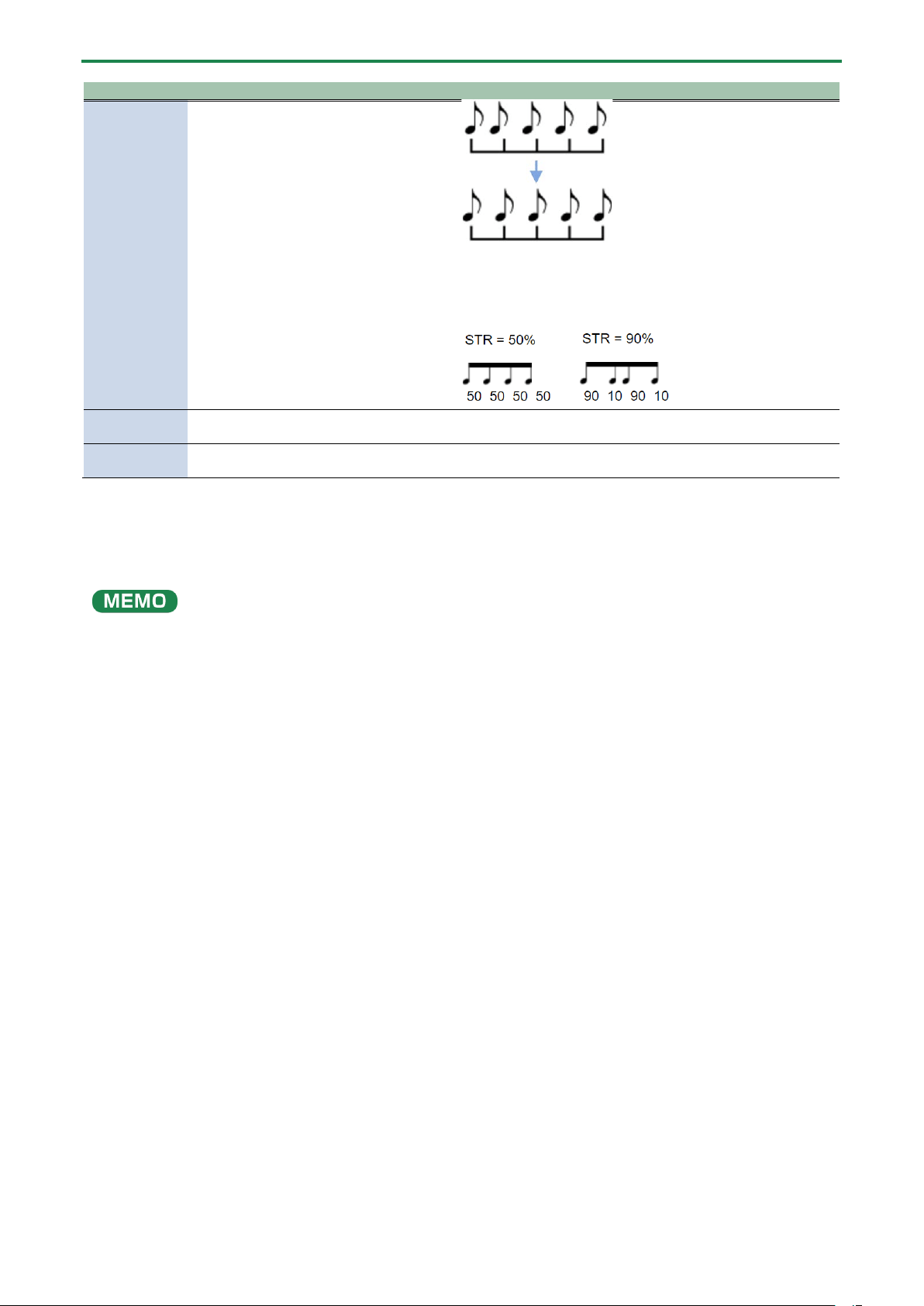
Combining Samples to Create a Pattern (PATTERN SEQUENCER)
77
Controller
Parameter
Value
Explanation
Lower values make the quantization less obvious, and a value of
0% results in no quantization.
If you’ve selected “SHUFFLE” for the QTZ parameter, a value of
50% makes the notes play at equal intervals, and larger values
make the notes play like dotted notes.
[SHIFT] button +
[CTRL 2] knob
QTZ.START
(QS)
Selects the start of the range for quantization.
[SHIFT] button +
[CTRL 3] knob
QTZ.END
(QE)
Selects the end of the range for quantization.
7.
Press the [VALUE] knob.
The “Quantize Pattern” message appears.
8.
Use the [VALUE] knob to select “OK,” and press the [VALUE] knob.
This corrects the timing at which the samples sound to match the specified interval.
Once you’ve quantized a pattern, you can’t revert to the way it was before.
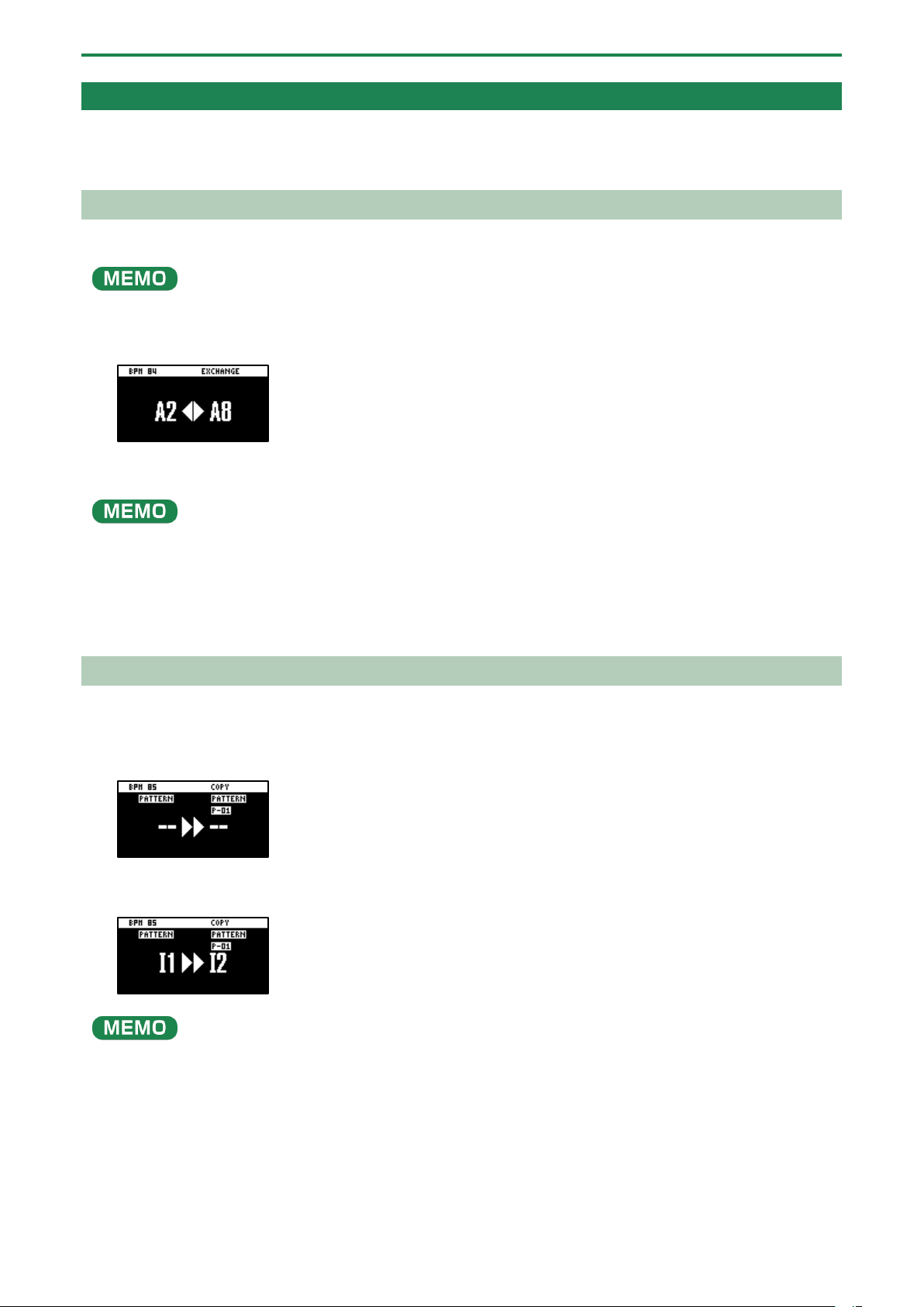
Combining Samples to Create a Pattern (PATTERN SEQUENCER)
78
Organizing the Pattern Data
This section explains the functions for making effective use of the patterns.
Exchanging (Swapping) Patterns Between Pads
Here’s how to exchange (swap) the patterns that are assigned to two different pads.
You can’t perform the following operations while a pattern is playing back. Stop the pattern before performing the operation.
1.
Hold down the [SHIFT] button and press the pad [5].
The EXCHANGE screen appears.
2.
Press the two pads in order, for which you want to exchange the patterns.
To cancel exchanging, press the [EXIT] button.
You can use the bank [A/F]–[E/J] buttons to select a bank before pressing the pads. It’s also possible to exchange patterns
between different banks.
3.
Press the [VALUE] knob or [COPY] button.
The patterns of the pads are now exchanged.
Copying the Pattern of a Pad
Here’s how to copy the pattern that’s assigned to a pad to a different pad.
1.
Press the [COPY] button.
The COPY screen appears.
2.
Press the pads in order, first the pattern (pad) you want to copy and then the copy destination pattern
(pad).
If you decide to cancel copying, press the [EXIT] button.
●
To copy a pattern to a different bank, first press the bank [A/F]–[E/J] buttons to select the bank before pressing the
pattern (pad) for the copy destination.
● You can use the [CTRL 3] knob to select a project, when copying the pattern to a different project.
● You can convert the selected pattern to a sample and then assign that sample to a pad. For details, refer to “Converting
Patterns to Samples (BOUNCE)(P.66).”
● You can create a pattern using only specific samples that were taken from a selected pattern. For details, refer to
“Extracting Specific Samples (Pads) from a Pattern(P.79).”
● You can also use “Converting Patterns to Samples(P.65)” together with “Extracting Specific Samples (Pads) from a
Pattern(P.79)”.
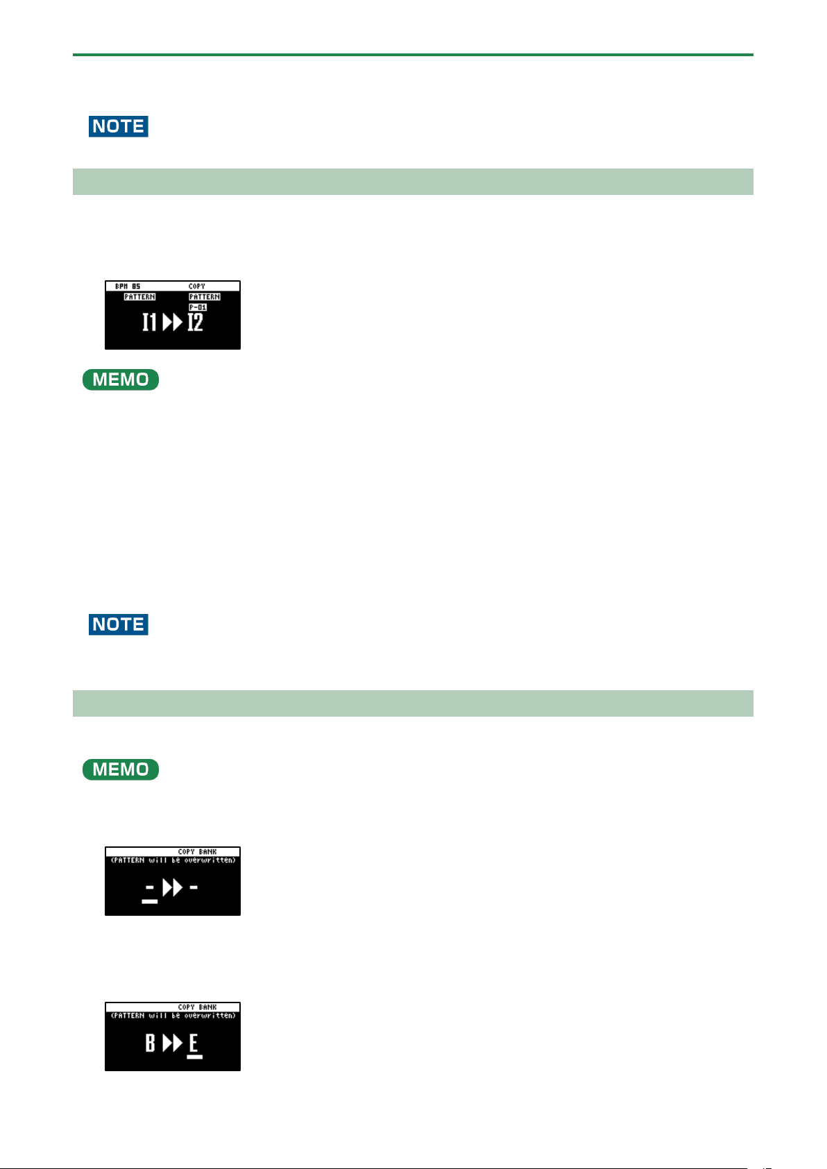
Combining Samples to Create a Pattern (PATTERN SEQUENCER)
79
3.
Press the [VALUE] knob or [COPY] button.
This copies the pattern.
Performing this operation overwrites (erases) the pattern in the copy destination pad.
Extracting Specific Samples (Pads) from a Pattern
You can create a pattern using only specific samples that were taken from a pattern that you’ve inputted using multiple samples.
1.
Following the steps in “Copying the Pattern of a Pad”, press the source pattern (pad) and then the save
destination pattern (pad).
If you decide to cancel, press the [EXIT] button.
●
If you use the bank [A/F]–[E/J] buttons to select the bank before pressing the pads, you can save the pattern to a different
bank.
● You can use the [CTRL 3] knob to select a project, when saving the pattern to a different project.
2.
Press the [REMAIN] button.
Samples (pads) that are used by a pattern light up dimly in white.
3.
Press the samples (pads) that you want to extract.
The pads light up white.
4.
Press the [REMAIN] button.
5.
Press the [VALUE] knob or [COPY] button.
The pattern for which only the selected samples are enabled is saved to the specified pad.
Performing this operation overwrites (erases) the pattern in the copy destination pad.
Copying all patterns in a bank to another bank
This is how to copy all the patterns in a bank to another bank.
You can’t perform the following operations while a pattern is playing back. Stop the pattern before performing the operation.
1.
Hold down the [COPY] button and press the [EXIT] button.
The COPY BANK screen appears.
2.
Press the bank [A/F]–[E/J] buttons to select the bank to copy (source).
3.
Turn the [VALUE] knob clockwise to move the cursor.
4.
Press the bank [A/F]–[E/J] buttons to select where to copy the bank (destination).
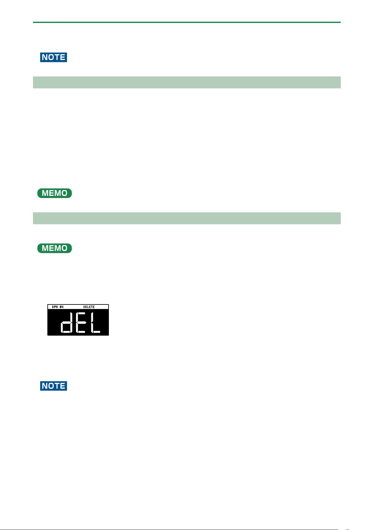
Combining Samples to Create a Pattern (PATTERN SEQUENCER)
80
5.
Press the [VALUE] knob or [COPY] button.
All the patterns in the bank are copied to the specified bank.
Performing this operation overwrites (erases) the pattern in the copy destination pad.
Protecting a Pattern (PROTECT)
This function prevents the samples and patterns assigned to a pad from being overwritten by being copied or edited, or
accidentally deleted.
Protection is set on a bank by bank basis. Protection is set for both samples and patterns.
1.
Press the bank [A/F]–[E/J] buttons to select the banks to protect.
To select banks F–J, press the bank [A/F]–[E/J] buttons twice to make them blink.
2.
Hold down the [SHIFT] button and press the [COPY] button.
A protect confirmation message appears.
To cancel the protect operation, press the [EXIT] button.
3.
Use the [VALUE] knob to select “OK”, and press the [VALUE] knob.
To cancel protection, do the same operation again.
Deleting the Pattern from a Pad
Here’s how to delete the pattern assigned to a pad.
You can’t perform the following operations while a pattern is playing back. Stop the pattern before performing the operation.
1.
Press the [DEL] button.
The DELETE screen appears.
2.
Press the pad containing the pattern that you want to delete.
If you decide to cancel deleting, press the [EXIT] button.
3.
Press the [VALUE] knob or [DEL] button.
The pattern for that pad is deleted.
You can’t restore a pad’s pattern after it has been deleted.
If you want to keep your data or make sure it doesn’t get accidentally modified, we recommend that you follow the steps in
“Backing up Your Data (BACKUP)(P.120)” to create regular backups.
Deleting all patterns in a bank at once
1.
Hold down the [DEL] button and press the [EXIT] button.
The DELETE BANK screen appears.

Combining Samples to Create a Pattern (PATTERN SEQUENCER)
81
2.
Press the bank [A/F]–[E/J] buttons.
Select a bank to delete.
3.
Press the [VALUE] knob.
The patterns in the selected bank are deleted.
You can’t restore a pad’s pattern after it has been deleted.
If you want to keep your data or make sure it doesn’t get accidentally modified, we recommend that you follow the steps in
“Backing up Your Data (BACKUP)(P.120)” to create regular backups.
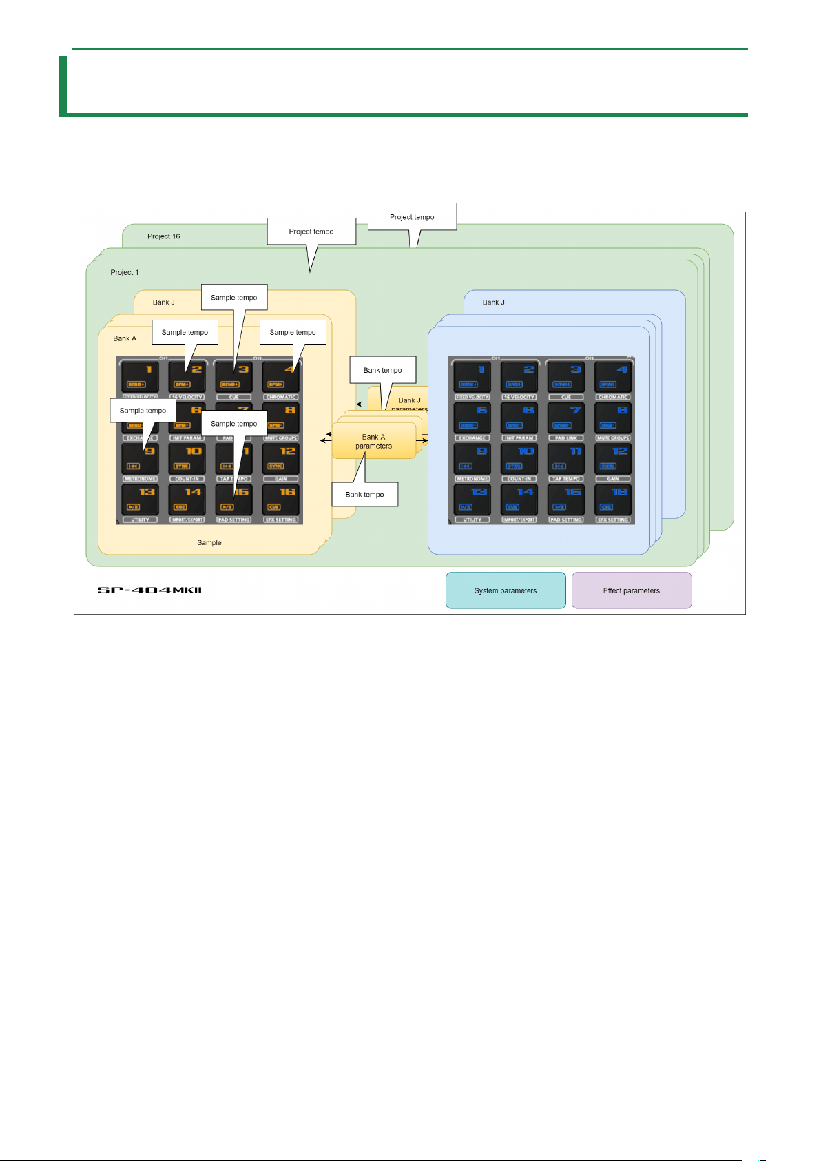
Setting the Tempo
82
Setting the Tempo
You can set the tempo data for samples and patterns.
This tempo data can be used to change the sample playback speed and pitch, so that you can play in tempo with other songs.
Here we explain about the different tempo data used by this unit.
Sample tempo
This is the tempo data used by individual samples.
When a pattern is not playing back, the sample tempo for the sample to play back is enabled (as the standard).
Bank tempo
This is the tempo data used by the banks.
This tempo is common for all samples and patterns saved within the same bank.
This tempo is enabled when the TEMPO SEL parameter is “BANK” (BANK A–BANK J).
The patterns play back at the tempo set for the bank tempo. If BPM SYNC is set to “ON” for a sample, the sample plays back at a
tempo converted from the speed that’s set as the bank tempo.
Project tempo
This is the tempo data used by a project.
This tempo is common for all samples and patterns saved within the same project.
This tempo is enabled when the TEMPO SEL parameter is “PROJECT”.
The patterns play back at the tempo set for the project tempo. If BPM SYNC is set to “ON” for a sample, the sample plays back at a
tempo converted from the speed that’s set as the project tempo.
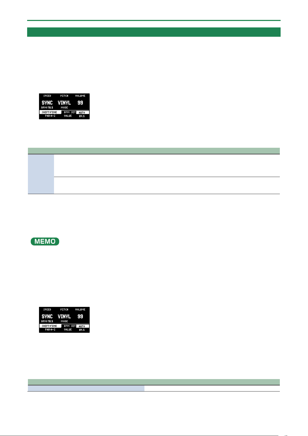
Setting the Tempo
83
Setting the Tempo Data in a Sample
You can set the tempo (BPM) of a sample to make the sample play back in sync with the tempo.
Setting the tempo in AUTO mode
Here’s how to detect and set the tempo of a sample.
1.
Press the [PITCH/SPEED] button.
The pitch/speed settings screen appears.
2.
Press pads [1]–[16] to select the sample you want to edit.
3.
Use the [VALUE] knob to change BPM SET to “AUTO,” and press the [VALUE] knob.
“BPM RANGE?” is shown.
Parameter
Value
Explanation
BPM
RANGE
SX (Length)
The same method of detecting tempo that’s used on the SP-404SX.
This detects the tempo according to the sample length.
This method is suitable for detecting the tempo when using a sample that’s up to
around ten seconds long.
100-199, 80-159, 70-139,
50-99
A method of detecting the tempo that’s unique to the SP-404MK2.
This analyzes the frequency characteristics over the entire sample to detect the tempo.
This specifies the value as the estimated tempo of the sample.
4.
Turn and then press the [VALUE] knob.
A confirmation message appears.
5.
Use the [VALUE] knob to select “OK,” and press the [VALUE] knob.
The sample is analyzed, and the detected tempo is set as the BPM value.
You may not be able to accurately detect the tempo (BPM) on some samples. If you’re having a hard time getting the right
tempo, try making the setting in MANUAL mode.
MANUAL mode
Here’s how to manually set the tempo. Use MANUAL mode if you know the tempo of the sample, or if you’re having a hard time
detecting the correct tempo in AUTO mode.
1.
Press the [PITCH/SPEED] button.
The pitch/speed settings screen appears.
2.
Press pads [1]–[16] to select the sample you want to edit.
3.
Turn the [VALUE] knob to change BPM SET to “MANU,” and press the [VALUE] knob.
Use the “MANU” setting to set the tempo in the 0.1 decimal range and the “MANU-F” setting to set the tempo in the 0.01
decimal range.
4.
Use the [VALUE] knob to select the BPM, and press the [VALUE] knob.
Parameter
Value
VALUE
40.00–200.00


Setting the Tempo
85
Setting the Tempo for a Bank or Project
By setting a tempo (BPM) for a bank, the same tempo is used for all patterns within the same bank or project during playback.
The tempo you set becomes the base tempo when playing back samples using BPM SYNC.
1.
Hold down the [SHIFT] button and press the pad [11].
The TEMPO SEL screen appears.
2.
Use the [CTRL 1] knob to select the base tempo used for BPM SYNC or for playing back patterns.
Value
Explanation
PROJECT
Uses the project tempo as the base tempo.
BANK A–BANK
J
Uses the bank tempo as the base tempo. The value displayed changes according to the currently
selected bank.
3.
Use the [VALUE] knob to set the tempo, and then press the [EXIT] button.
●
Hold down the [SHIFT] button and turn the [VALUE] knob to set the decimal value of the tempo.
● You can also set the tempo using the tap tempo function.
→
“Setting the Tempo in Time with the Rhythm (Tap Tempo)(P.86)”
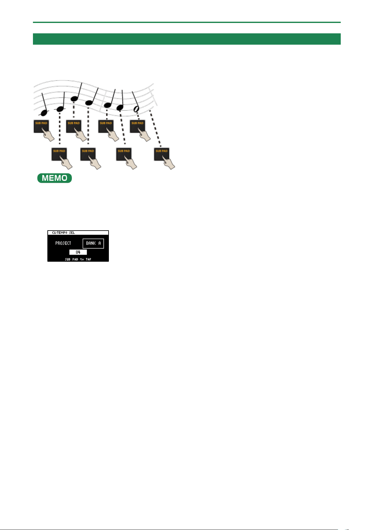
Setting the Tempo
86
Setting the Tempo in Time with the Rhythm (Tap Tempo)
This feature lets you set the tempo in an intuitive way by tapping the pad in time, as if you were clapping out the beat (Tap
Tempo).
This is useful function when you want to play in time with other instruments or to the rhythm of a song.
The tap tempo function is enabled when the [SUB PAD] button is blinking orange.
On the input setting screen and other screens, tap tempo is automatically enabled.
1.
Hold down the [SHIFT] button and press the pad [11].
This enables the tap tempo function. When this happens, the [SUB PAD] button blinks orange.
2.
Tap the [SUB PAD] button several times in time with the beat.
The tempo (BPM) appears on the screen to indicate the interval (timing) at which you’re tapping the [SUB PAD] button.
3.
Once you’ve confirmed the tempo setting, press the [EXIT] button.
This exits the tap tempo screen. This tempo is set for the project or bank.
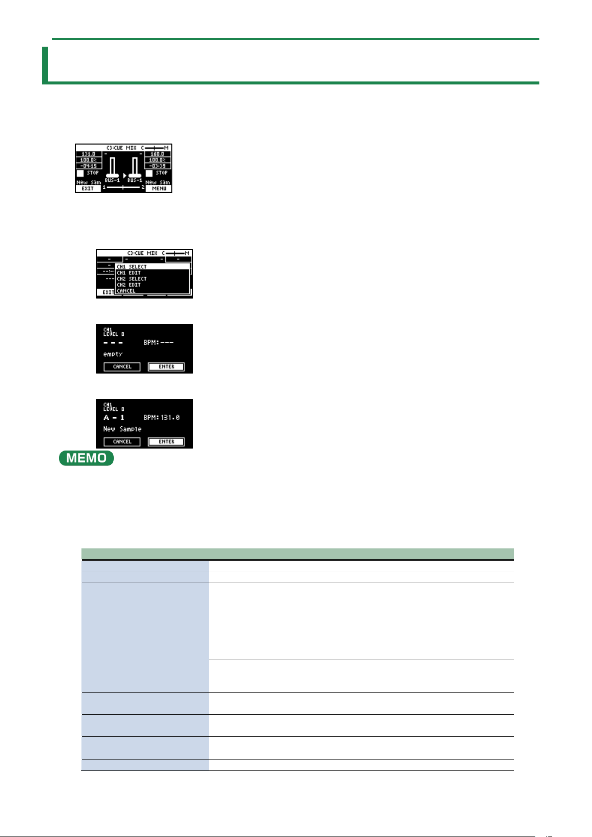
Mixing the Samples (DJ MODE)
87
Mixing the Samples (DJ MODE)
You can assign two samples to CH1 and CH2 and mix them freely.
1.
Press the bank [D/I] button and the [E/J] button simultaneously.
The unit enters DJ MIXER mode.
2.
Select the samples to respectively assign to CH1 and CH2.
1.
Press the [VALUE] knob.
A menu appears.
2.
Use the [VALUE] knob to select “CH1 SELECT” or “CH2 SELECT,” and press the [VALUE] knob.
3.
Press pads [1]–[16] to select the sample to assign to either CH1 or CH2.
Press a pad to preview its sample. You may not be able to hear the samples at this time if the CH1 LEVEL or CH2 LEVEL is too
low. Turn the [CTRL 1] or [CTRL 2] knobs to adjust the volume.
4.
Use the [VALUE] knob to select “ENTER,” and press the [VALUE] knob.
5.
Once you’ve assigned a sample to CH1, use the same operation to assign a sample to CH2.
6.
Use the [CTRL 1]–[CTRL 3] knobs and press pads [1]–[16] to mix the sound.
Controller
Parameter
Action
[CTRL 1] knob
CH1 LEVEL
Adjusts the volume of CH1.
[CTRL 2] knob
CH2 LEVEL
Adjusts the volume of CH2.
[CTRL 3] knob
● Use the [START/END]
button to switch
between functions for
the [CTRL 3] knob.
CUE MIX
Adjusts the balance of the audio you monitor via the PHONES
jack.
When this is set to the “C” side, you can monitor the sample
audio sent to CUE.
When this is set to the “M” side, you can monitor the audio
output to the LINE OUT jacks and the USB port.
→
“Monitoring with Headphones (CUE)(P.95)”
X-FADE
Crossfades between CH1 and CH2.
You can make CH2 fade in while CH1 is fading out, or the
opposite.
CH1: Pad [13]
CH2: Pad [15]
ñ
Switches between play/pause.
CH1: Pad [9]
CH2: Pad [11]
õ
Returns to the playback start position.
CH1: Pad [14]
CH2: Pad [16]
CUE
Sends the sample audio to CUE.
→
“Monitoring with Headphones (CUE)(P.95)”
Pad [10] or pad [12]
SYNC
Synchronizes the tempo (BPM) of two samples.
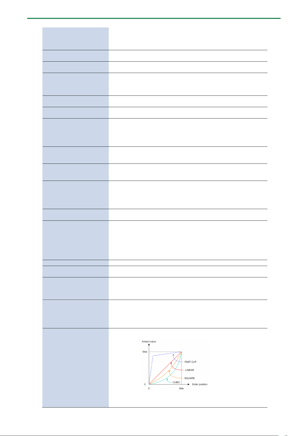
Mixing the Samples (DJ MODE)
88
When pad [10] is pressed, the CH1 sample follows the tempo of
the CH2 sample.
When pad [12] is pressed, the CH2 sample follows the tempo of
the CH1 sample.
CH1: Pad [2]
CH2: Pad [4]
BPM+
Speeds up the tempo.
CH1: Pad [6]
CH2: Pad [8]
BPM-
Slows down the tempo.
CH1: [DEL] button + Pad [2] +
Pad [6]
CH2: [DEL] button + Pad [4] +
Pad [8]
BPM
Resets the tempo to the default value.
CH1: Pad [1]
CH2: Pad [3]
BEND+
The pitch goes up while you hold down the pad. This also
speeds up the playback, like an analog turntable.
CH1: Pad [5]
CH2: Pad [7]
BEND-
The pitch goes down while you hold down the pad. This also
slows down the playback, like an analog turntable.
CH1: [REMAIN] button + Pad
[14]
CH2: [REMAIN] button + Pad
[16]
BUS FX
You can set the bus to which the CH1/CH2 sample playback is
sent (meaning which effects are used).
While holding down the [REMAIN] button, each time you press
pad [14] or pad [16] switches the effect to use as follows: “BUS-
1” -> “BUS-2” -> “DRY” -> “BUS-1”.
CH1: [ROLL] button + Pad [13]
CH2: [ROLL] button + Pad [15]
Repeats the sample playback in more detailed intervals (ROLL).
Note that when the ROLL SIZE (roll interval) is longer than the
sample length, a roll cannot played back.
[SHIFT] button + [ROLL] knob
ROLL SIZE
Sets the roll interval (1/4, 1/2, 1 or 2 measures).
Set the ROLL SIZE before playing back rolls. (You can’t change
the ROLL SIZE with this operation while a roll is playing back).
[ROLL] button + pads [1]–[4]
Changes the roll interval while the roll is playing back.
[ROLL] button + pad [1]: quarter-note (1/4 of a measure)
[ROLL] button + pad [2]: half-note (1/2 of a measure)
[ROLL] button + pad [3]: whole note (1 measure)
[ROLL] button + pad [4]: two whole notes (2 measures)
[START/END] button
Switches between the functions (CUE MIX or X-FADE) for the
[CTRL 3] knob.
[PITCH/SPEED] button
Changes the number of digits shown for the BPM.
Each time you press the [PITCH/SPEED] button, the display
switches in the following order: integers only -> to the second
decimal place -> to the first decimal place -> integers only....
When you set the BPM value using pads [2] [4] (BPM+) and pads
[6] [8] (BPM-), the number of digits shown for the BPM changes
according to the minimum unit.
[MARK] button
Switches between the EFX and MIXER screen views.
[BPM SYNC] button
Selects the channel (CH1/CH2) used to control reverse playback
([REVERSE] button).
[REVERSE] button
REVERSE
Starts reverse playback immediately from the playback position
of the current sample.
When playing back in reverse, this works the same as when the
“Reverse Type(P.124)” system parameter is set to “303”.
CH1: [SHIFT] button +
[REVERSE] button + Pad [13]
CH2: [SHIFT] button +
[REVERSE] button + Pad [15]
MUTE
Mutes the sample that’s playing back.
Press [RESAMPLE] button +
[VALUE] knob
VOLUME
CURVE
Selects the volume curve characteristics used for each slider
(CH1 LEVEL, CH2 LEVEL, X-FADE) in DJ mode.
Each time you hold down the [RESAMPLE] button and press the
[VALUE] knob, the characteristic switches in this order: “FAST
CUT” -> “LINEAR” -> “SQUARE” -> “CUBIC” -> “FAST CUT”.
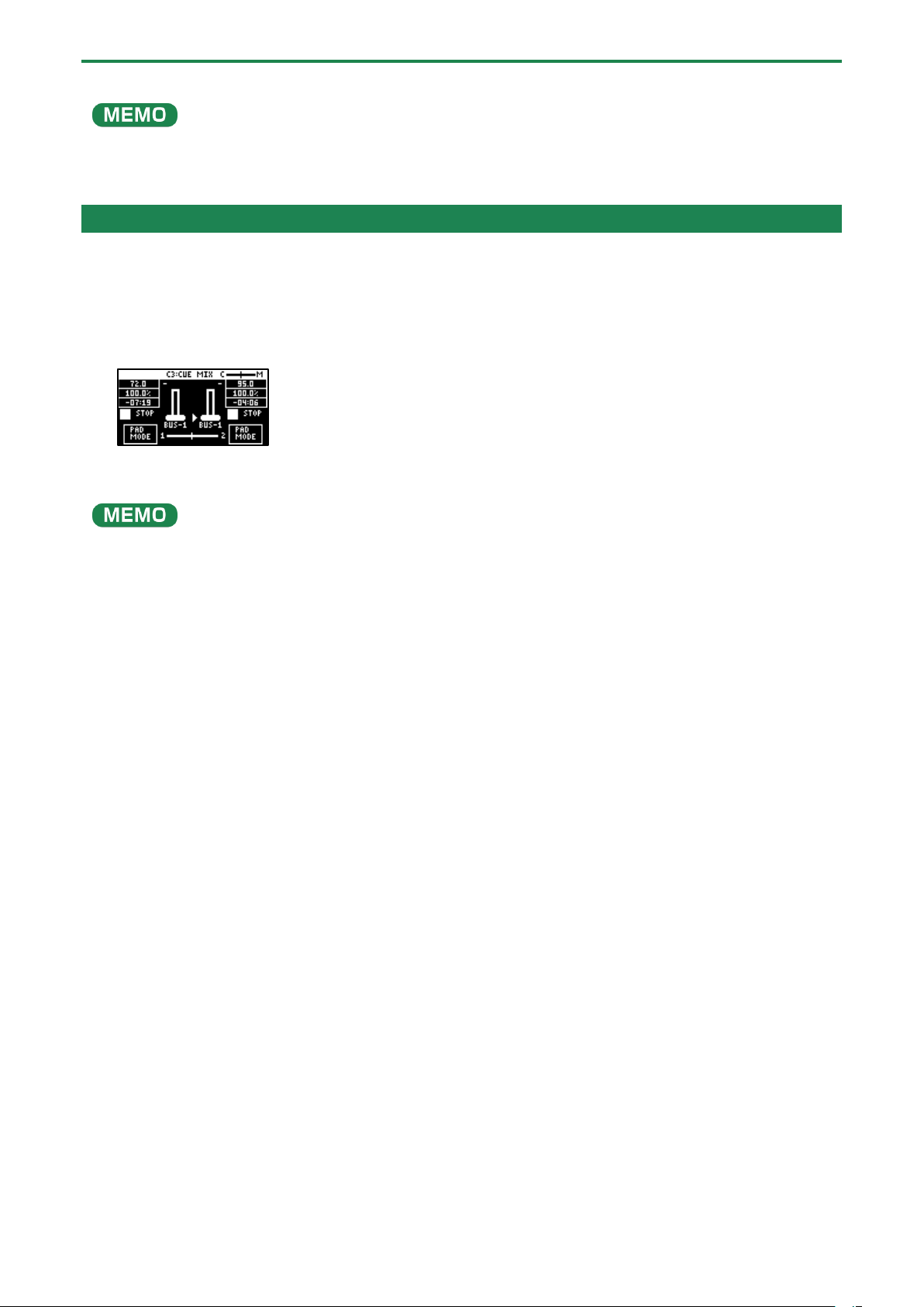
Mixing the Samples (DJ MODE)
89
This lets you change how the pitch sounds (how the audio is processed) when changing the playback speed of a sample in DJ
mode.
For details, refer to “DJ mode TS type(P.124)”.
Playing Back Samples While in DJ Mode (PAD MODE)
In this mode (pad mode), you can temporarily change the pad arrangement to the same arrangement used in sample mode, while
still retaining the same functions of DJ mode.
Pad mode lets you play back samples by pressing pads while you perform in DJ mode.
1.
While in DJ mode, press the [HOLD] button.
This switches between DJ mode and pad mode.
2.
Press pads [1]–[16].
The samples assigned to the pads are played back.
You can play back samples as long as the sample in question is not being used in DJ mode.
The samples (pads) that are blinking orange are being used in DJ mode, so their samples can’t be played back.

Mixing the Samples (DJ MODE)
90
Playing Back Patterns While in DJ Mode
In DJ mode, you can play back the patterns that you created.
1.
Press the [PATTERN SELECT] button.
2.
Press pads [1]–[16] to select a pattern to play back.
3.
Press the [PATTERN SELECT] button.
4.
Press the [PATTERN EDIT] button.
The [PATTERN EDIT] button blinks, and the pattern playback screen appears.
5.
Press the pad [13].
This plays back the pattern.
Use the [CTRL 1]–[CTRL 3] knobs and press pads [1]–[16] to mix the sound, as with the samples.

Mixing the Samples (DJ MODE)
91
Playing Back a Sample from the Marker Position
You can play back a sample from the position of the marker that’s set for that sample.
1.
Press pad [13] or [15].
The corresponding samples play back.
2.
Hold down the [SHIFT] button and press pads [1]–[16].
The samples play back from the marker positions set for the samples.
The relationship between the markers where playback begins and the pads are as follows.
CH1 sample
CH2 sample
1: Beginning of sample
2: Marker 1
3: Beginning of sample
4: Marker 1
5: Marker 2
6: Marker 3
7: Marker 2
8: Marker 3
9: Marker 4
10: Marker 5
11: Marker 4
12: Marker 5
13: Marker 6
14: Marker 7
15: Marker 6
16: Marker 7
●
Markers up through the seventh marker from the beginning of the sample are recognized in DJ mode.
Markers from the eighth marker onwards are ignored (and cannot be selected).
● When you press pads [1]–[16] while holding down the [SHIFT] button, playback begins immediately from the specified
marker, even if a sample is already playing back.
● If you press the [REMAIN] button while holding down the [SHIFT] button, the [SHIFT] button remains in a pressed-down
state, even after you take your fingers off the buttons.
Selecting a marker makes playback easier. Press the [EXIT] button to cancel this behavior.
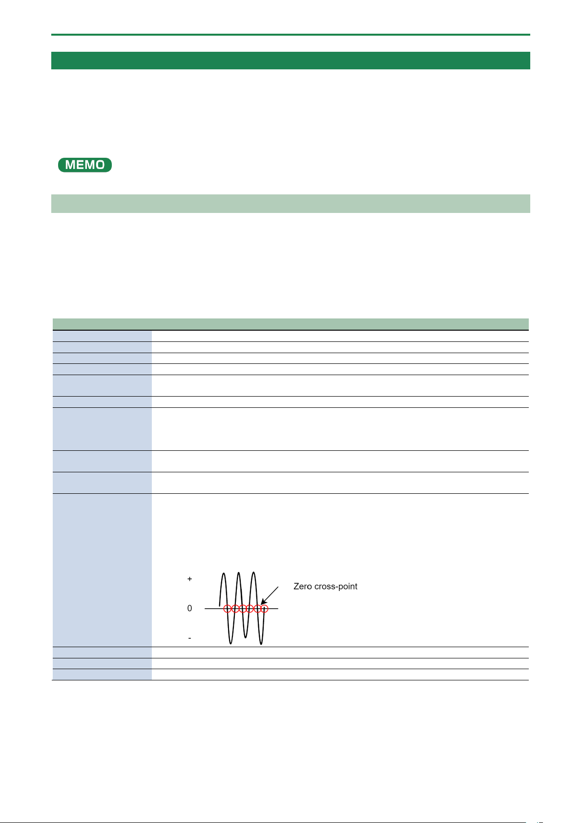
Mixing the Samples (DJ MODE)
92
Adding a Marker While Playing Back a Sample
You can add markers while playing samples in DJ mode.
1.
Play back a sample.
2.
Hold down the [SHIFT] button and press the [MARK] button at the position where you want to add a
marker.
This adds a marker to the sample.
You can add up to seven markers.
Editing a Marker While Playing Back a Sample
You can edit markers while playing samples in DJ mode.
1.
Press pad [13] or [15].
The corresponding samples play back.
2.
Hold down the [SHIFT] button and press the [START/END] button.
The marker edit screen appears.
Controller
Action
[MARK] button
Adds a marker.
[CTRL 1] knob
Moves the cursor.
[CTRL 2] knob
Moves the marker.
[CTRL 3] knob
Selects a marker.
[SHIFT] button + [CTRL]
knob (turn)
Zooms the area around each point in/out.
[VALUE] knob (turn)
Zooms the area in/out around each point you just manipulated.
[VALUE] knob (press)
You can use a numerical value to set the position of each point.
Use the [VALUE] knob to select the point to set, and press pads [1]–[10] to input the position (press
pad [10] to input a “0”).
To confirm the inputted position, press the [VALUE] knob.
[SHIFT] button + [VALUE]
knob (turn)
Adjusts the volume of the channel.
[DEL] button + pads [1]–
[8]
Deletes the marker.
[RESAMPLE] button
Moves the start point to the zero cross-point (*) that’s closest to the start point time (SNAP to Zero-
Cross function).
Similarly, the loop point and end point are also moved.
This function is enabled when the [RESAMPLE] button is lit.
* The “zero cross-point” is the time at which the value of the sample waveform crosses from zero
into a positive or negative number.
[ROLL] button
While this button is pressed, you can preview the sound several seconds before the end point.
Pad [13]
Switches between play/pause.
Pad [9]
Returns to the playback start position.

Mixing the Samples (DJ MODE)
93
Deleting All Set Markers from a Sample
While in DJ mode, you can delete the markers you’ve set for samples.
1.
Hold down the [SHIFT] and [DEL] buttons, and press pads [1]–[16].
Select the marker to delete.
The relationship between the markers to delete and the pads are as follows.
CH1 sample
CH2 sample
1:
2: Marker 1
3:
4: Marker 1
5: Marker 2
6: Marker 3
7: Marker 2
8: Marker 3
9: Marker 4
10: Marker 5
11: Marker 4
12: Marker 5
13: Marker 6
14: Marker 7
15: Marker 6
16: Marker 7
●
As pads [1] and [3] are at the start of the sample, they can’t be deleted (these are not markers).
● When you delete a marker, all following markers are moved back in sequence.
● Markers up through the seventh marker from the beginning of the sample are recognized in DJ mode.
Markers from the eighth marker onwards are ignored (and cannot be deleted).
Note that when you delete a marker from 1 to 7, all of the following markers are moved back in sequence, so you can delete the eighth
marker in this case.
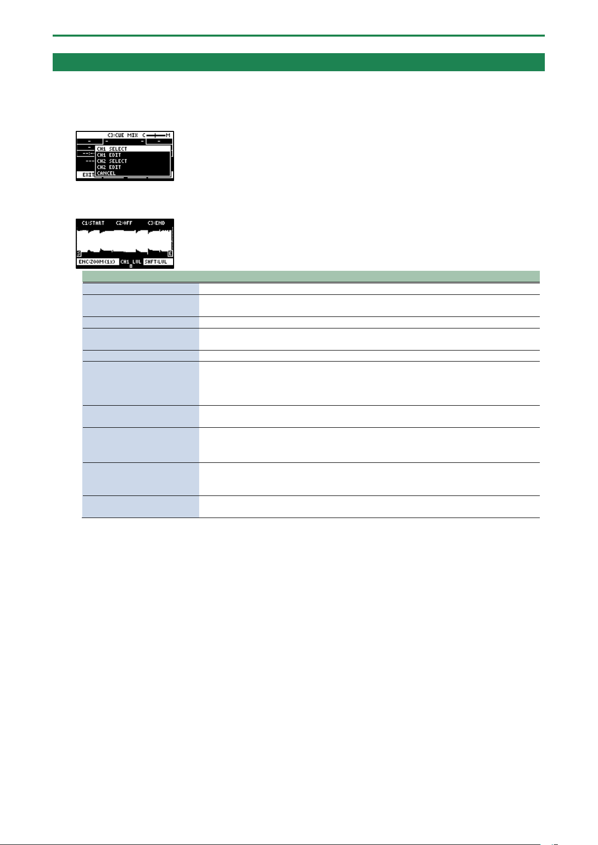
Mixing the Samples (DJ MODE)
94
Editing a Sample in DJ Mode
You can edit the samples that are used in DJ mode.
1.
Press the [VALUE] knob.
A menu appears.
2.
Use the [VALUE] knob to select “CH1 EDIT” or “CH2 EDIT,” and press the [VALUE] knob.
The sample edit screen appears. The editing method is the same as for sample edit in sample mode.
Controller
Action
[CTRL 1] knob
Moves the start point.
[CTRL 2] knob (when the
loop is on)
Moves the loop point.
[CTRL 3] knob
Moves the end point.
[SHIFT] button + [CTRL]
knob (turn)
Zooms the area around each point in/out.
[VALUE] knob (turn)
Zooms the area in/out around each point you just manipulated.
[VALUE] knob (press)
You can use a numerical value to set the position of each point.
Use the [VALUE] knob to select the point to set, and press pads [1]–[10] to input the
position (press pad [10] to input a “0”).
To confirm the inputted position, press the [VALUE] knob.
[SHIFT] button + [VALUE]
knob (turn)
Adjusts the volume of the channel.
[DEL] button
Initializes the start and end point positions.
● When a confirmation message appears, use the [VALUE] knob to select “OK,” and
press the [VALUE] knob.
[REMAIN] button
On: Prevents the start point from being moved beyond the loop point or the end point.
Off: When the start point moves beyond the loop point or the end point, this moves the
loop point or the end point as well.
[ROLL] button
While this button is pressed, you can preview the sound several seconds before the end
point.
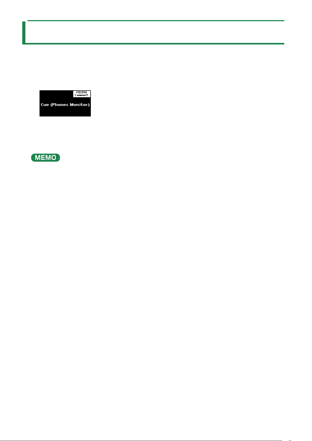
Monitoring with Headphones (CUE)
95
Monitoring with Headphones (CUE)
Adjusts the balance of the audio output from the PHONES jack.
When the sample audio is sent to CUE, the audio is only output from the PHONES jack (and is not output to the LINE OUT jack or
USB port). When playing live or in similar situations, only the player can preview (check) the sample’s sound in headphones.
1.
Hold down the [SHIFT] button and press the pad [3].
The unit switches to CUE mode.
2.
Adjust the volume balance with the CTRL [3] knob.
When this is set to the “C” side, you can monitor the sample audio sent to CUE. When this is set to the “M” side, you can
monitor the audio output to the LINE OUT jacks and the USB port.
3.
To exit CUE mode, press the [EXIT] button.
You can’t send two or more samples to CUE at the same time (playback is not possible).
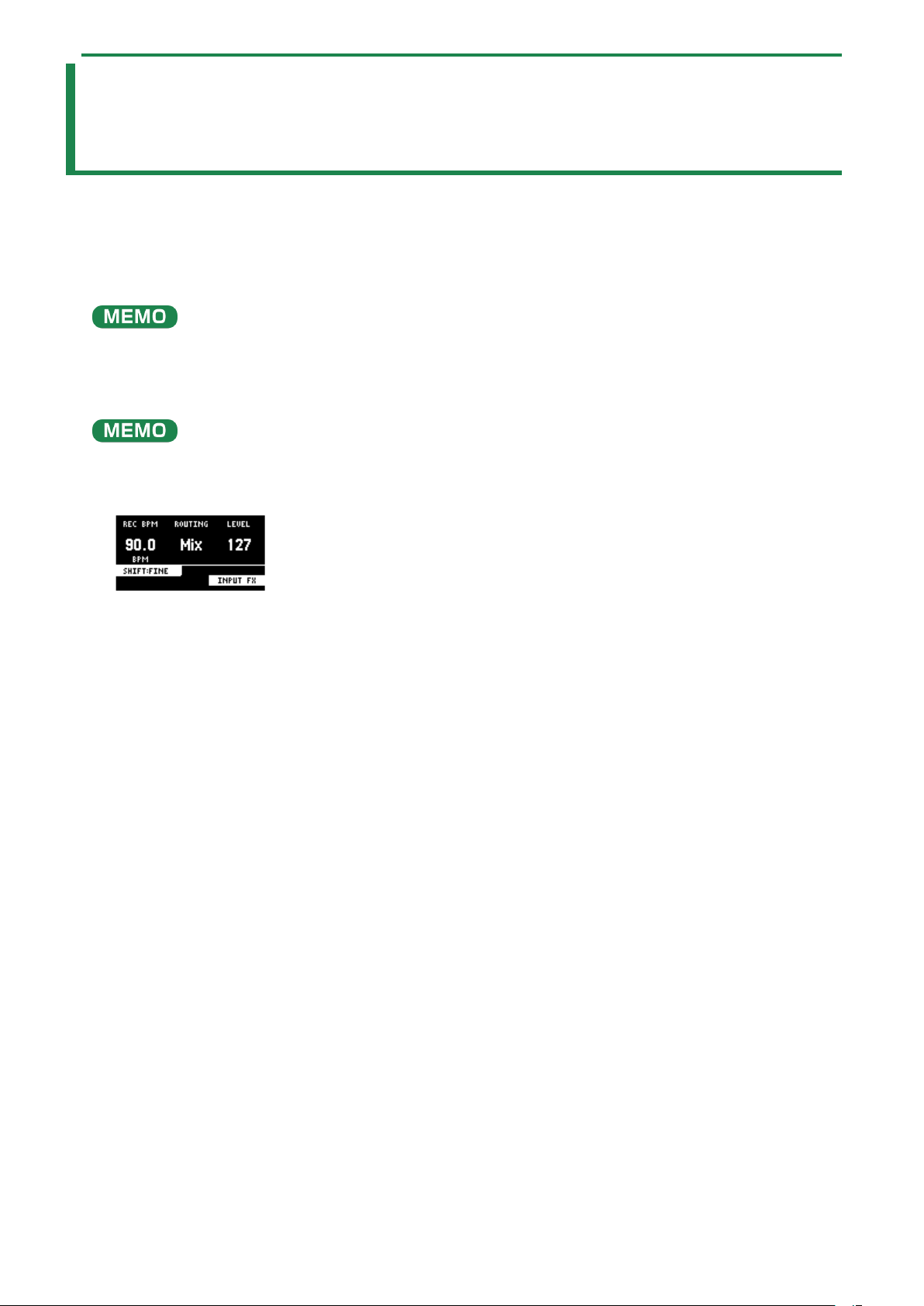
Inputting Sound from an Electronic Musical Instrument, Mic or Guitar
96
Inputting Sound from an Electronic Musical
Instrument, Mic or Guitar
You can connect your electronic musical instrument, mic or guitar to the SP-404MK2 for audio input.
1.
Connect an electronic musical instrument to the LINE IN jack(s) on the rear panel. When using a mic or
guitar, plug them into the INPUT jack on the front panel.
You can connect high-impedance devices like guitars and bass guitars to the INPUT jack on the front panel. When connecting a
guitar or bass guitar, set the [MIC/GUITAR] switch on the front panel to the right-hand side.
2.
Press the [EXT SOURCE] button.
The [EXT SOURCE] button lights up. This inputs the audio of the connected device.
The [EXT SOURCE] button blinks red if the level of the input signal is too high. In this case, the input audio may sound distorted.
3.
Hold down the [SHIFT] button and press the [EXT SOURCE] button.
The input setting screen appears.
4.
Turn the [CTRL 3] knob to adjust the volume of the audio input.
When you raise the volume, the audio is output from the connected device.
5.
When you finish making the settings, press the [EXIT] button.
6.
To stop the audio input from the connected device, press the [EXT SOURCE] button.
The [EXT SOURCE] button goes dark. This stops the audio from the connected device.

Inputting Audio from a Computer or Mobile Device (USB AUDIO)
97
Inputting Audio from a Computer or Mobile
Device (USB AUDIO)
The SP-404MK2 can receive audio input from a computer or mobile device (such as a smartphone or tablet).
Configuring the OS audio settings
You must make the appropriate settings on your computer when inputting audio from a computer to the SP-404MK2.
For Windows
1.
Open the Control Panel.
2.
Click the “Hardware and Sound” icon, and then click the “Sound” icon.
If the panel is displaying as icons or in classic view, double-click the [Sound] icon.
3.
Click the [Playback] tab.
4.
Click “Speakers SP-404MKII-G”, and click the “Set Default” button.
5.
Click the [OK] button.
For macOS
1.
Open the System Preferences.
2.
Click the [Sound] icon.
3.
Click the [Output] tab and select [SP-404MKII-OUT].
4.
Close the System Preferences.
Enabling audio from a computer or mobile device
1.
Connect your computer to the SP-404MK2 with a USB cable.
2.
Press the [EXT SOURCE] button on the SP-404MK2.
3.
The [EXT SOURCE] button is lit. Input the audio from your computer or mobile device into the SP-
404MK2.

Selecting a Project
98
Selecting a Project
Here’s how to recall a project (1–16).
Once a project is recalled, the unit is ready to play back samples and create patterns.
1.
Hold down the [SHIFT] button and press the [SUB PAD] button.
The SELECT PROJECT screen appears.
2.
Press pads [1]–[16] to select a project you want to recall.
The project is recalled. Once the project is recalled, the top screen appears.
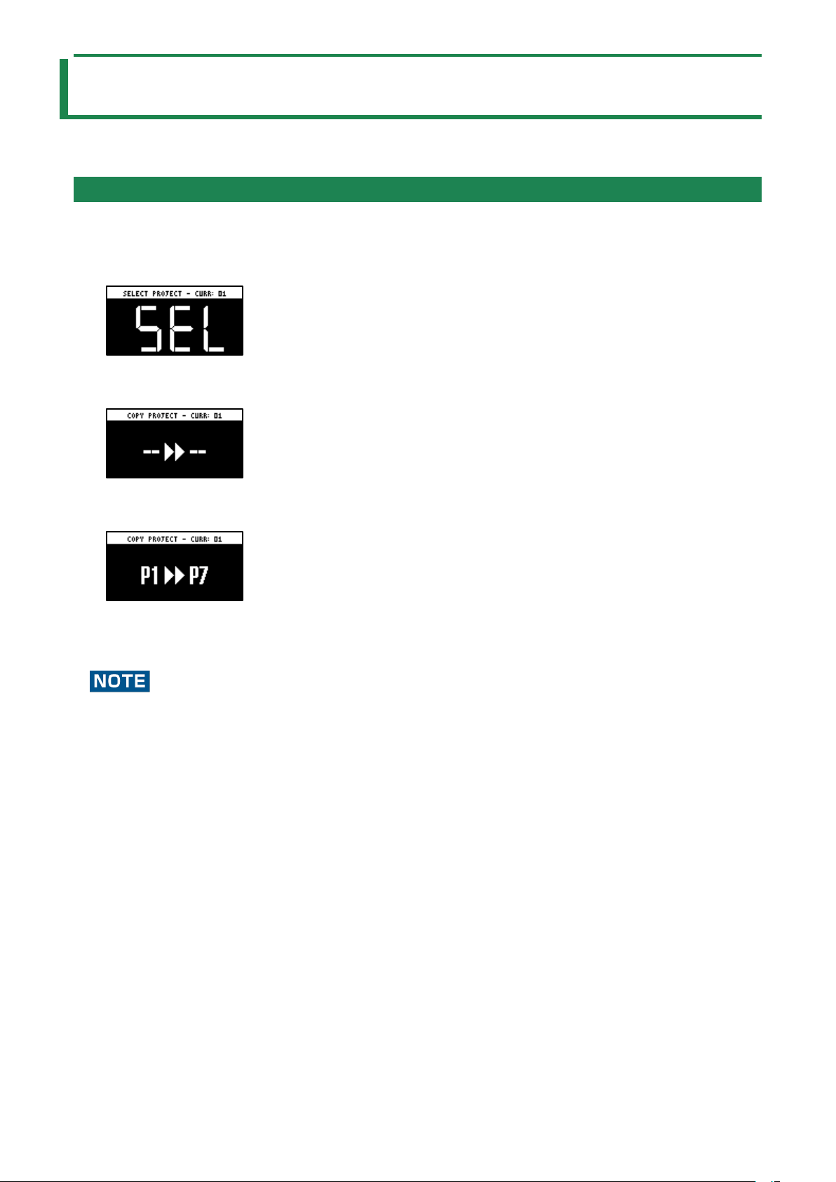
Organizing Projects
99
Organizing Projects
On this unit, you can copy projects and delete projects you no longer need.
Copying a Project
Here’s how to copy a project.
1.
Hold down the [SHIFT] button and press the [SUB PAD] button.
The SELECT PROJECT screen appears.
2.
Press the [COPY] button.
The COPY PROJECT screen appears.
3.
Press the pads in order, beginning with the pad you want to copy (project), and then the copy
destination pad.
If you decide to cancel copying, press the [EXIT] button.
4.
Press the [VALUE] knob or [COPY] button.
The project is now copied.
Performing this operation overwrites (erases) the project in the copy destination pad.
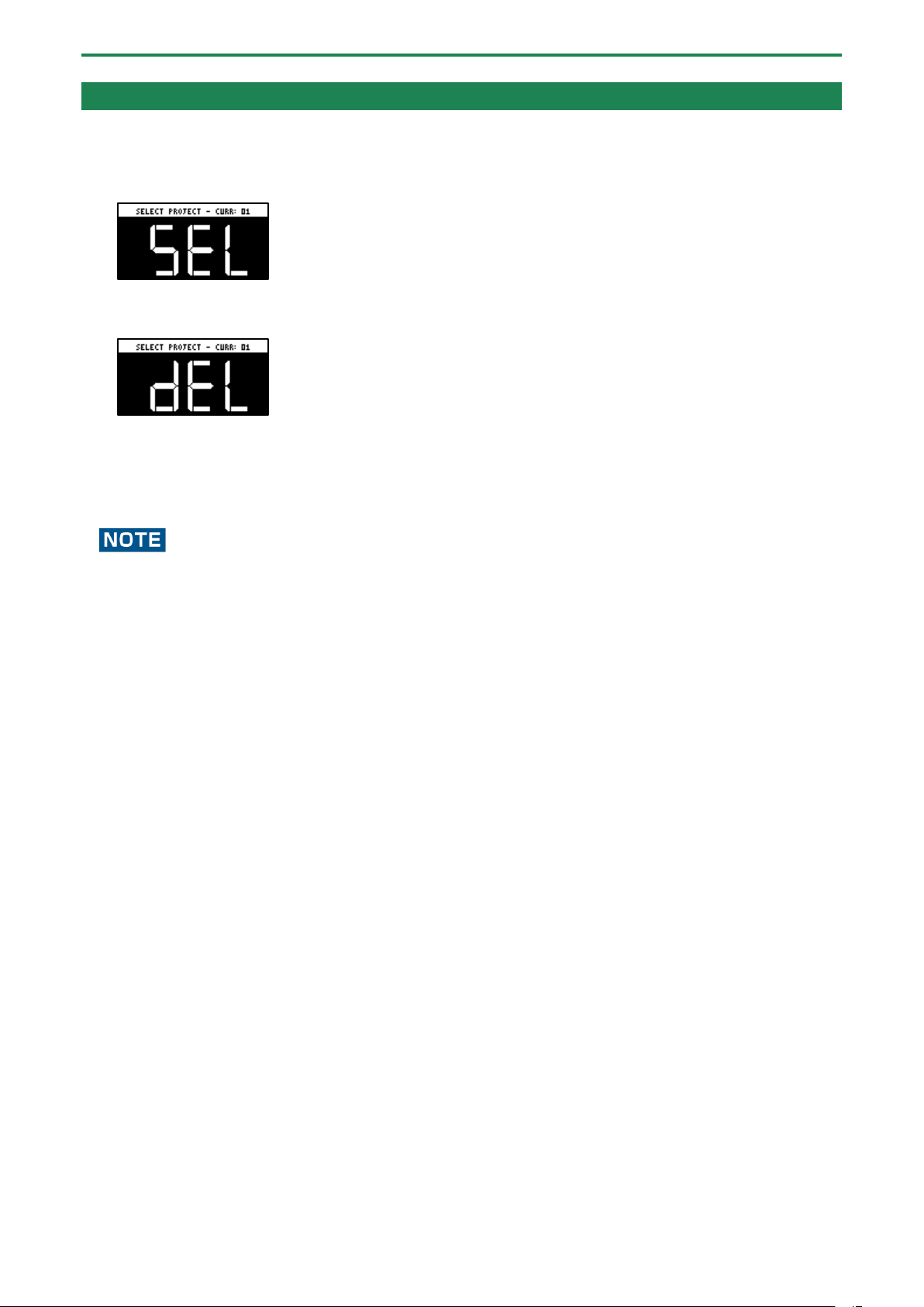
Organizing Projects
100
Deleting a Project
Here’s how to delete projects you don’t need.
1.
Hold down the [SHIFT] button and press the [SUB PAD] button.
The SELECT PROJECT screen appears.
2.
Press the [DEL] button.
The project deletion screen appears.
3.
Press pads [1]–[16] to select the project to delete.
If you decide to cancel deleting, press the [EXIT] button.
4.
Press the [VALUE] knob or [DEL] button.
This deletes the project data.
You can’t restore a project after it has been deleted.
If you want to keep your project data or make sure it doesn’t get accidentally modified, we recommend that you follow the
steps in “Backing up Your Data (BACKUP)(P.120)” to create regular backups.
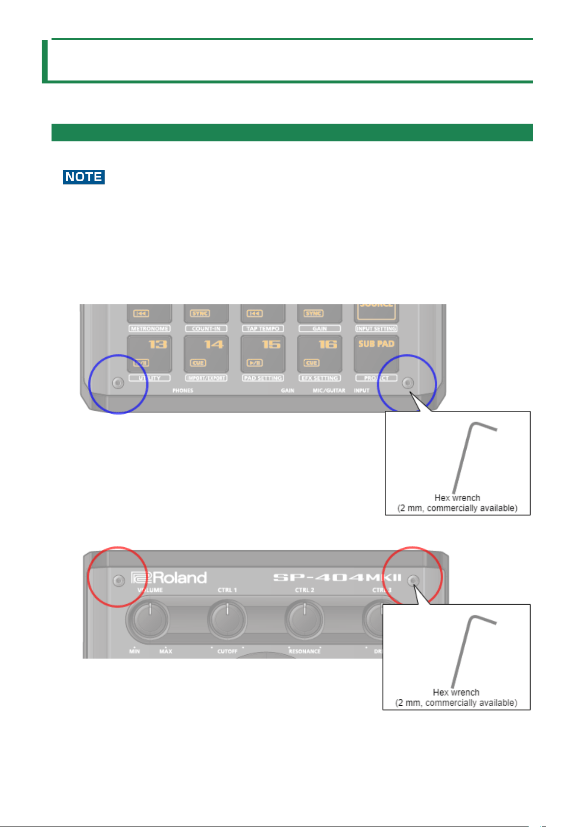
Customizing This Unit
101
Customizing This Unit
You can customize the design of this unit to match your tastes.
Attaching/Removing the Faceplate of This Unit
You can remove the faceplate of this unit to customize the top panel.
●
Make sure you don’t cut your fingers on the edges when removing or attaching the faceplate.
● The faceplate may bend if it is exposed to strong impact when removed. If this happens, you may not be able to reattach
it.
Removing the faceplate
1.
Use a commercially available hex wrench (2 mm) to remove the two screws (at the front of the unit)
circled in blue.
2.
Remove the screws (at the far side of the unit) circled in red.
Attaching the faceplate

Customizing This Unit
102
To attach the faceplate, follow the steps for removing the top panel in reverse order.
1.
Use a commercially available hex wrench (2 mm) to attach the two screws (at the far side of the unit)
circled in red.
2.
Install the two screws (at the front of the unit) circled in blue.
Overtightening the screws may damage the screw holes.

Customizing This Unit
103
Customizing the Opening Screen
You can use your own custom images for the opening screen.
Two opening images can be registered per project.
Steps for setting your custom image data as the opening image
You must perform the following operations (summarized) to use your custom image data as the opening image.
1.
Create your custom image (Preparing a Screen Saver Image(P.104)).
2.
Export the project to an SD card (Exporting a Project (EXPORT PROJECT)(P.119)).
3.
Save your custom images to the SD card (Saving the Screen Saver Image to a Project(P.105)).
4.
Load the project from the SD card (Importing a Project (IMPORT PROJECT)(P.118)).
Preparing an Opening Image
Create your custom image in the format shown below.
Format
Specifications
Image file format
BMP
Size
128 (x) × 64 (y) pixels
Color depth
1-bit, 4-bit, 8-bit, 24-bit
● Note that only monochromatic images can be displayed. Intermediate colors cannot be displayed.
Filename and
extension
startup_*.bmp
Substitute a number (1–2) for the asterisk. The unit does not recognize filenames in any other format. If
the filename is not recognized, the default opening screen is shown.
Saving an Opening Image to a Project
Here’s how to save your custom image to a project. As an example, the following shows how to change the opening image of
project 01 to your own custom image.
1.
Export the project for which you want to change the opening image (project 01 in this example) to an
SD card (“
Exporting a Project (EXPORT PROJECT)(P.119)”).
2.
Remove the SD card from this unit, and open the contents on your computer.
3.
Copy the opening image that’s saved in the SD card to the “EXPORT/PROJECT/PROJECT_01/PICTURE”
folder. Change the filename to “startup_*.bmp”, replacing the asterisk with a number from 1 to 2.
For details on the “/EXPORT/PROJECT/PROJECT_01/PICTURE” folder, see the folder structure diagram shown in
“Importing/Exporting (Using the SD Card)(P.114)”.
4.
Remove the SD card from your computer, and insert it into this unit.
5.
Import the project in which the opening image is registered (“Importing a Project (IMPORT
PROJECT)
(P.118)”).
Your custom opening image is displayed from the next time the unit starts up.
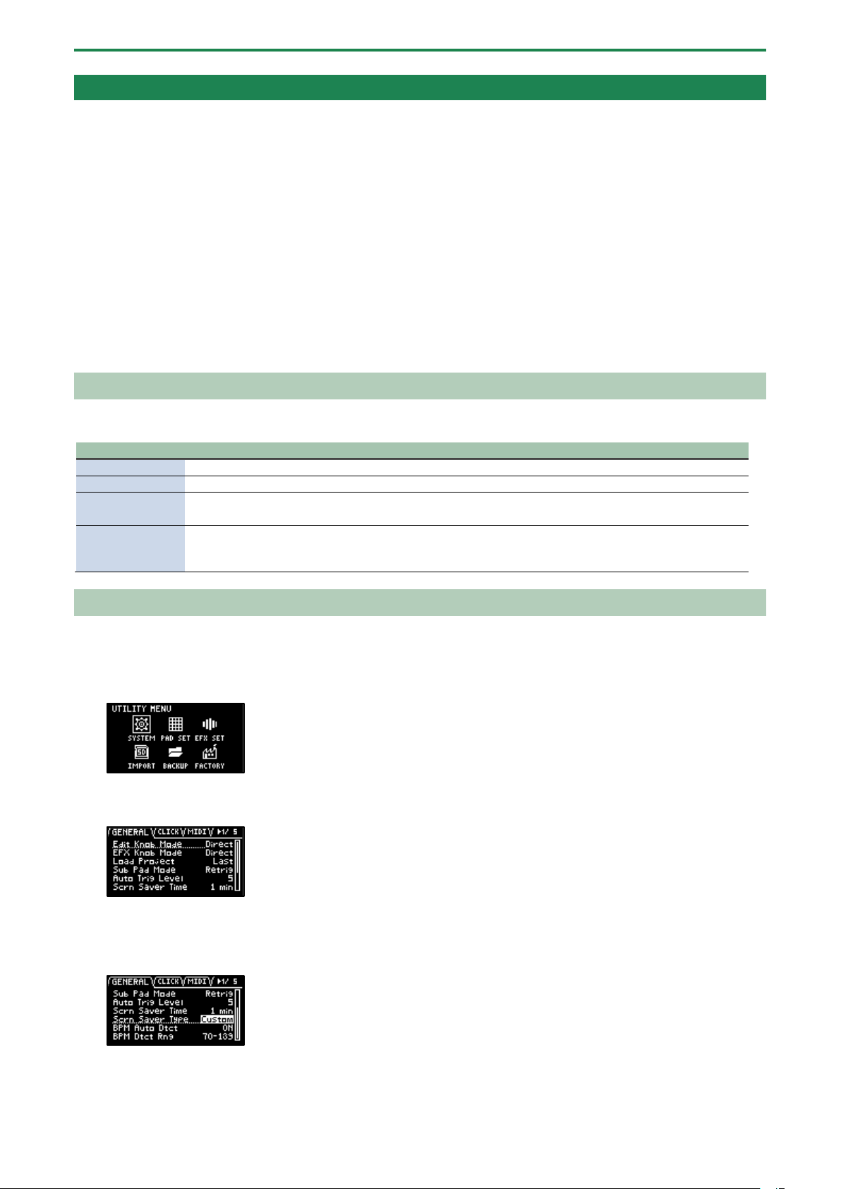
Customizing This Unit
104
Customizing the Screen Saver
You can set your own custom image as the screen saver image.
A maximum of 16 screen saver images can be registered per project.
Steps for using your custom images as the screen saver
You must perform the following operations (summarized) to use your custom images as the screen saver.
1.
Create your custom image (Preparing a Screen Saver Image(P.104)).
2.
Switch the settings to use a custom screen saver (Enabling a Custom Screen Saver(P.104)).
3.
Export the project to an SD card (Exporting a Project (EXPORT PROJECT)(P.119)).
4.
Save your custom images to the SD card (Saving the Screen Saver Image to a Project(P.105)).
5.
Load the project from the SD card (Importing a Project (IMPORT PROJECT)(P.118)).
Preparing a Screen Saver Image
Create your custom image in the format shown below.
Format
Specifications
Image file format
BMP
Size
128 (x) × 64 (y) pixels
Color depth
1-bit, 4-bit, 8-bit, 24-bit
● Note that only monochromatic images can be displayed. Intermediate colors cannot be displayed.
Filename and
extension
screen_saver_*.bmp
Substitute a number (1–16) for the asterisk. The unit does not recognize filenames in any other format. If
the filename is not recognized, the default screen saver is shown.
Enabling a Custom Screen Saver
This shows how you can load a custom image as a screen saver (the “Screen Saver Type” parameter).
1.
Hold down the [SHIFT] button and press the pad [13].
The UTILITY MENU screen appears.
2.
Use the [VALUE] knob to select “SYSTEM”, and press the [VALUE] knob.
The system screen appears.
3.
Turn the [CTRL 3] knob to select the “GENERAL” tab.
4.
Use the [VALUE] knob to move the cursor to “Screen Saver Type”, and press the [VALUE] knob.
The value display is highlighted, and you can now edit the value.
5.
Use the [VALUE] knob to select “Custom”, and press the [VALUE] knob.
6.
Press the [EXIT] button.

Customizing This Unit
105
Saving the Screen Saver Image to a Project
Here’s how to save your custom image to a project. As an example, the following shows how to edit the custom image for the
screen saver of project 01.
1.
Prepare the image to use for the screen saver, and edit the settings to use a custom screen saver
(“
Preparing a Screen Saver Image(P.104)” and “Enabling a Custom Screen Saver(P.104)”).
2.
Export the project for which you want to change the screen saver (project 01 in this example) to an SD
card (“
Exporting a Project (EXPORT PROJECT)(P.119)”).
3.
Remove the SD card from this unit, and open the contents on your computer.
4.
Copy the screen saver image that’s saved in the SD card to the
“EXPORT/PROJECT/PROJECT_01/PICTURE” folder. Change the filename to “screen_saver_*.bmp”,
replacing the asterisk with a number from 1 to 16.
For details on the “/EXPORT/PROJECT/PROJECT_01/PICTURE” folder, see the folder structure diagram shown in
“Importing/Exporting (Using the SD Card)(P.114)”.
5.
Remove the SD card from your computer, and insert it into this unit.
6.
Import the screen saver image into the project where it was registered (“Importing a Project (IMPORT
PROJECT)
(P.118)”).
The screen saver that uses your custom screen saver is shown.
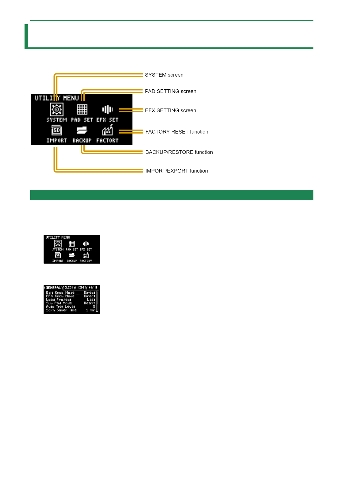
Configuring the Various Settings (UTILITY)
106
Configuring the Various Settings (UTILITY)
This menu lets you edit the parameters and view information related to the overall unit.
Editing the Settings Related to this Unit (System)
Here’s how to configure the overall settings for this unit.
1.
Hold down the [SHIFT] button and press the pad [13].
The UTILITY MENU screen appears.
2.
Use the [VALUE] knob to select “SYSTEM”, and press the [VALUE] knob.
The system setting screen appears. Each parameter is shown as divided into five tabs (groups).
3.
Turn the [CTRL 3] knob to select a tab.
Select the tab of the parameter you want to edit.
4.
Turn the [VALUE] knob to move the cursor to the parameter that you want to edit, and press the
[VALUE] knob.
The value display is highlighted, and you can now edit the value.
For details on the parameters, refer to “SYSTEM(P.123)” in the Parameter Guide.
5.
Turn the [VALUE] knob to edit the value, and press the [VALUE] knob.
This confirms the value.
6.
Press the [EXIT] button to return to the UTILITY MENU screen.
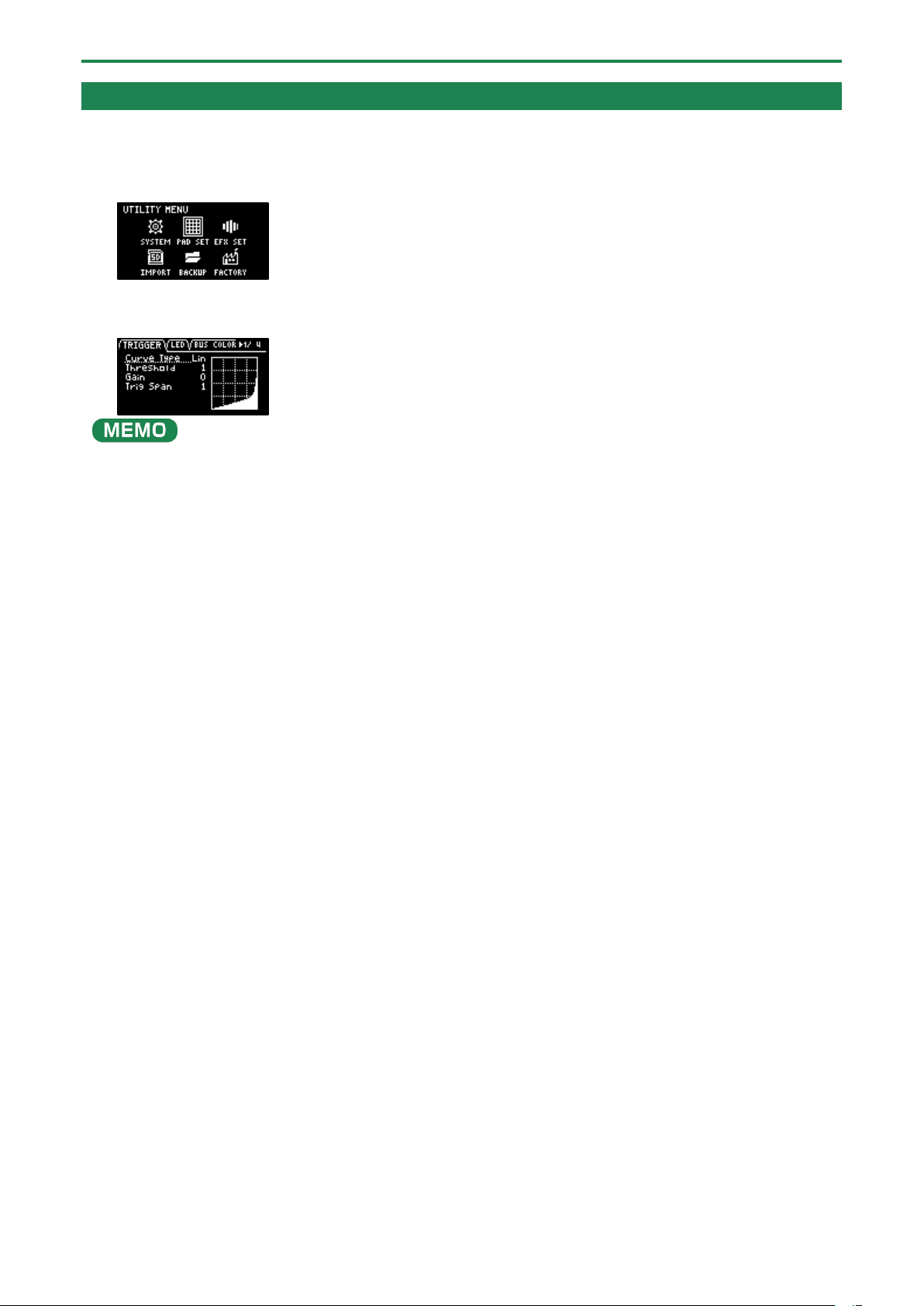
Configuring the Various Settings (UTILITY)
107
Configuring the Pad-related Settings (PAD SETTING)
The pad setting screen lets you configure various pad-related settings.
1.
Hold down the [SHIFT] button and press the pad [13].
The UTILITY MENU screen appears.
2.
Use the [VALUE] knob to select “PAD SET”, and press the [VALUE] knob.
The pad setting screen appears.
From the top screen, you can also make this screen appear by pressing pad [15] while holding down the [SHIFT] button.
3.
Turn the [CTRL 3] knob to select a tab.
The PAD SETTING screen is divided into four tabs (groups). Select the tab of the group that contains the parameter you want
to edit.
4.
Use the [VALUE] knob to move the cursor to the parameter you wish to edit, and press the [VALUE]
knob.
The value display is highlighted, and you can now edit the value.
For details on the parameters, refer to “PAD SET(P.126)” in the Parameter Guide.
5.
Turn the [VALUE] knob to edit the value, and press the [VALUE] knob.
6.
Press the [EXIT] button to return to the UTILITY MENU screen.
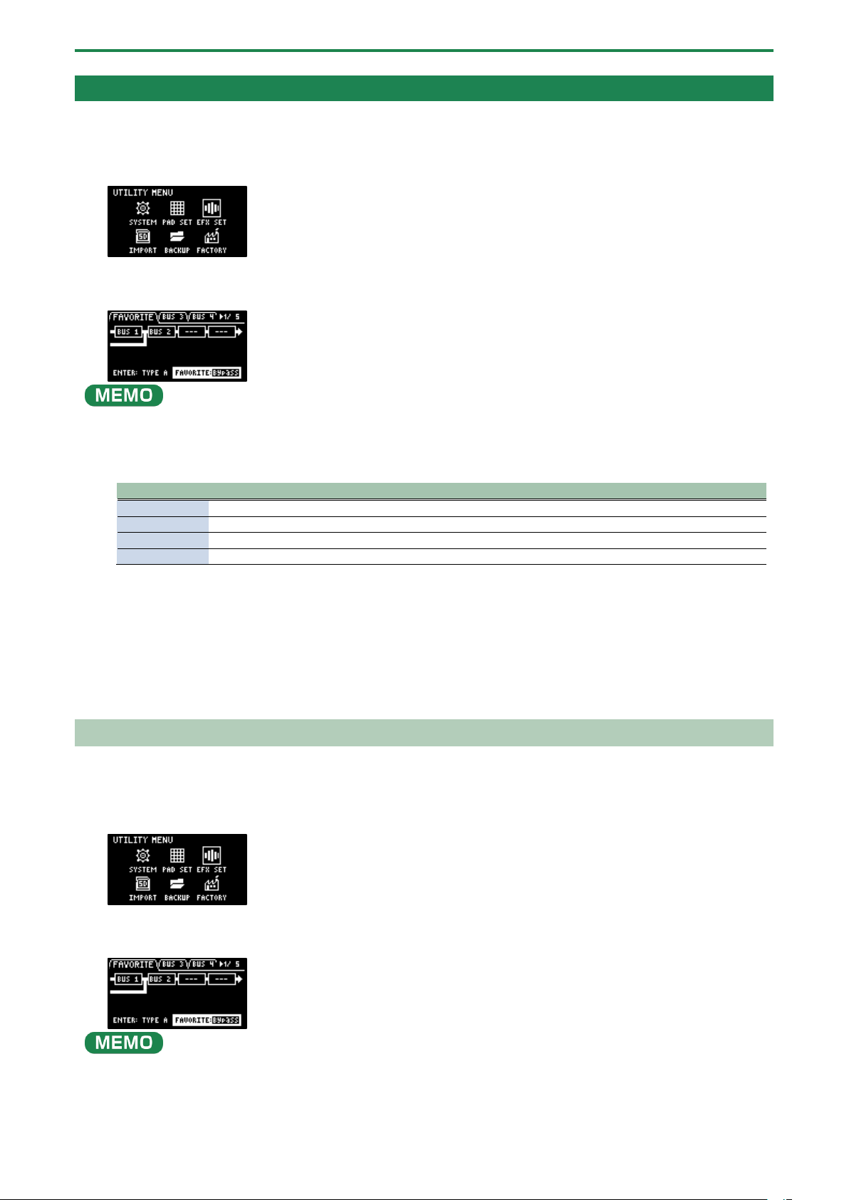
Configuring the Various Settings (UTILITY)
108
Configuring the Effect Settings (EFX SET)
This shows how to edit the routing (connection order) for the effects built into this unit, and how to configure the effects to use.
1.
Hold down the [SHIFT] button and press the pad [13].
The UTILITY MENU screen appears.
2.
Use the [VALUE] knob to select “EFX SET”, and press the [VALUE] knob.
The effect setting screen appears. Each parameter is shown as divided into five tabs (groups).
From the top screen, you can also make this screen appear by pressing pad [16] while holding down the [SHIFT] button.
3.
Turn the [CTRL 3] knob to select a tab.
4.
Select the tab of the parameter you want to edit.
Tab
Explanation
FAVORITE
Shows the current BUS FX settings. Use the [VALUE] knob to change the FAVORITE number.
BUS 3, BUS 4
Edits the parameters of the effects (BUS 3, BUS 4) applied to the overall sound.
DIRECT
You can assign the effects you like to the effect buttons on the top panel.
OTHER
Sets the BUS FX routing and effects to apply to external input.
5.
Use the [VALUE] knob to move the cursor to the parameter you wish to edit, and press the [VALUE]
knob.
The value display is highlighted, and you can now edit the value.
For details on the parameters, refer to “Parameter Guide(P.123)”.
6.
Turn the [VALUE] knob to edit the value, and press the [VALUE] knob.
7.
Press the [EXIT] button to return to the UTILITY MENU screen.
Configuring the Effect Routing
This shows how to edit the routing (connection order) for the effects built into this unit.
1.
Hold down the [SHIFT] button and press the pad [13].
The UTILITY MENU screen appears.
2.
Use the [VALUE] knob to select “EFX SET”, and press the [VALUE] knob.
The effect setting screen appears.
From the top screen, you can also make this screen appear by pressing pad [16] while holding down the [SHIFT] button.
3.
Use the [CTRL 3] knob to select “FAVORITE”, and press the [VALUE] knob.
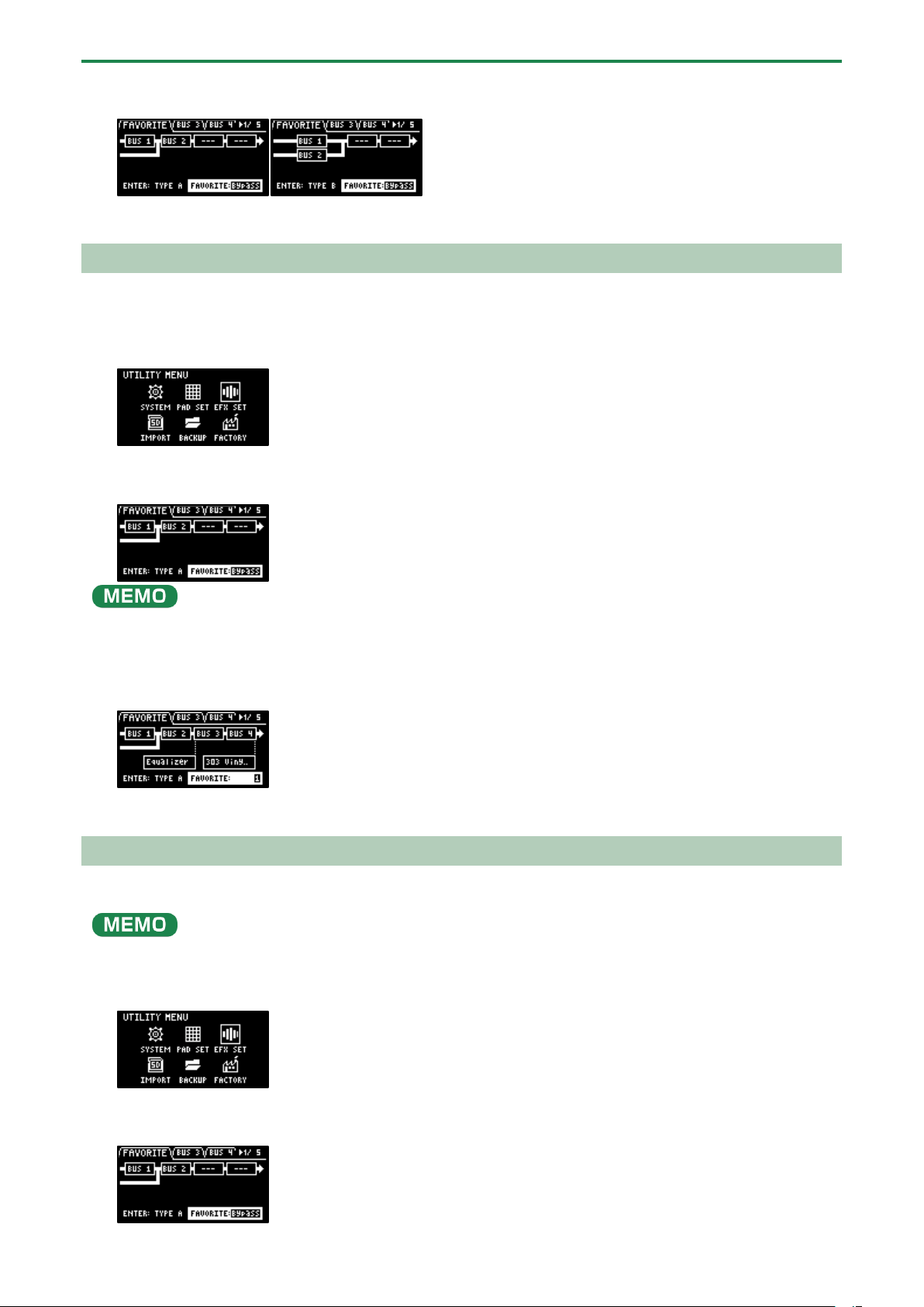
Configuring the Various Settings (UTILITY)
109
The position of the effect assigned to BUS 1 and BUS 2 changes each time you press the [VALUE] knob (“Using the
Effects(P.29)”).
4.
To finish making the settings, press the [EXIT] button.
Adding Effects to the Overall Sound (BUS 3, BUS 4)
Here’s how to apply effects to the overall sound output from this unit.
1.
Hold down the [SHIFT] button and press the pad [13].
The UTILITY MENU screen appears.
2.
Use the [VALUE] knob to select “EFX SET”, and press the [VALUE] knob.
The effect setting screen appears.
From the top screen, you can also make this screen appear by pressing pad [16] while holding down the [SHIFT] button.
3.
Turn the [CTRL 3] knob to select “FAVORITE”.
4.
Turn the [VALUE] knob to select “FAVORITE 1” through “FAVORITE 16”.
The effects you selected in “FAVORITE 1” through “FAVORITE 16” are applied to the overall output audio.
5.
To finish making the settings, press the [EXIT] button.
Changing the Effects Assigned to BUS 3 and BUS 4
Changes the type of effects to apply to the overall sound.
Refer to “Adding Effects to a Sample (BUS FX)(P.29)” to change the type of effects (BUS 1, BUS 2) that are applied to the samples.
1.
Hold down the [SHIFT] button and press the pad [13].
The UTILITY MENU screen appears.
2.
Use the [VALUE] knob to select “EFX SET”, and press the [VALUE] knob.
The effect setting screen appears.
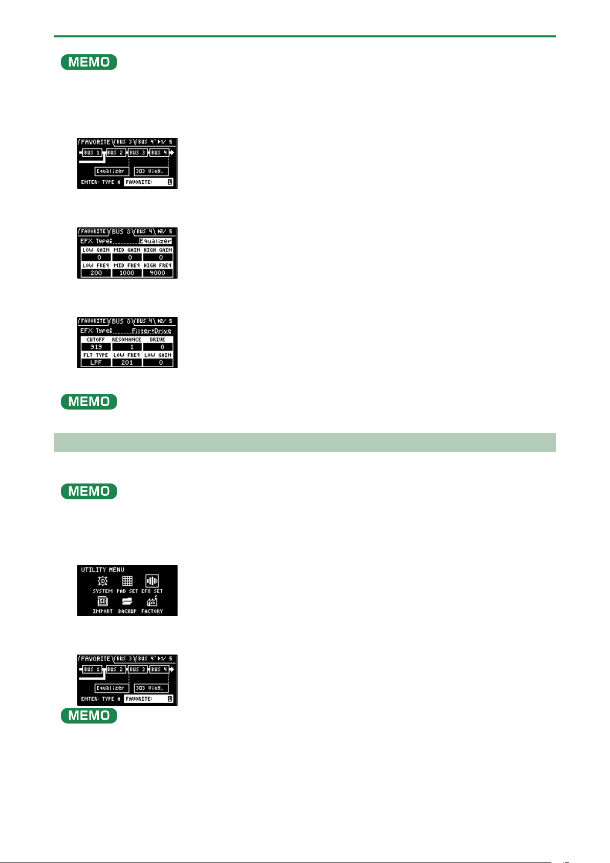
Configuring the Various Settings (UTILITY)
110
From the top screen, you can also make this screen appear by pressing pad [16] while holding down the [SHIFT] button.
3.
Turn the [CTRL 3] knob to select “FAVORITE”.
4.
Turn the [VALUE] knob to select “FAVORITE 1” through “FAVORITE 16”.
The effects you selected in “FAVORITE 1” through “FAVORITE 16” are applied to the overall output audio.
5.
Use the [CTRL 3] knob to select “BUS 3” or “BUS 4”, and press the [VALUE] knob.
The value display is highlighted, and you can now change the effects.
6.
Use the [VALUE] knob to select the effect, and press the [VALUE] knob.
This confirms the EFX Type.
7.
To finish making the settings, press the [EXIT] button.
Press the [BUS FX] button while holding down the [VALUE] knob to temporarily bypass the BUS 3 and BUS 4 effects.
Editing the Effects for BUS 3 and BUS 4
Here’s how to edit the effects (BUS 3, BUS 4) applied to the overall sound.
See “Editing the Effects(P.33)” for how to edit the effects (BUS 1, BUS 2) applied to a sample.
1.
Hold down the [SHIFT] button and press the pad [13].
The UTILITY MENU screen appears.
2.
Use the [VALUE] knob to select “EFX SET”, and press the [VALUE] knob.
The effect setting screen appears.
From the top screen, you can also make this screen appear by pressing pad [16] while holding down the [SHIFT] button.
3.
Use the [CTRL 3] knob to select “BUS 3” or “BUS 4”.
Select the bus whose effect you wish to change.
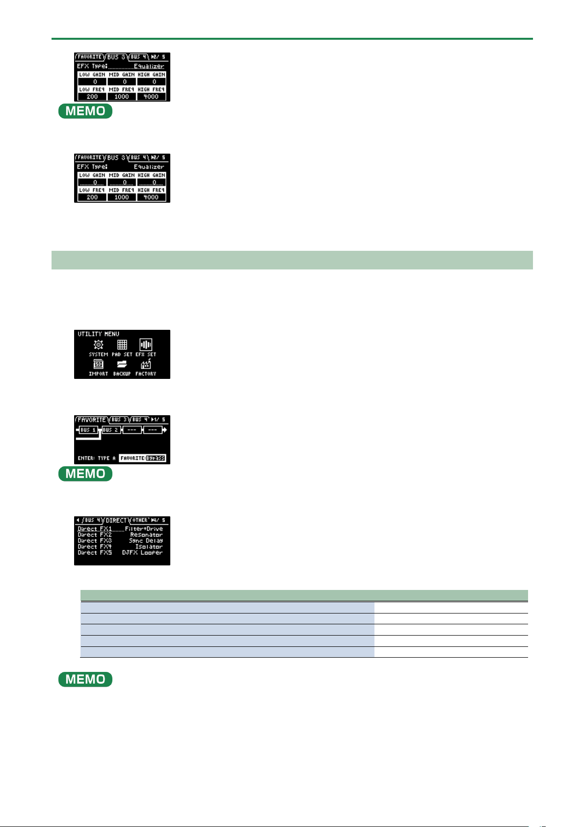
Configuring the Various Settings (UTILITY)
111
To edit BUS 3 and BUS 4, you must select a favorite from “FAVORITE 1” to “FAVORITE 16” in the “FAVORITE” tab screen.
4.
Turn the [VALUE] knob to set the parameter to edit.
5.
Use the [CTRL 1]–[CTRL 3] knobs to edit the parameter.
6.
To finish making settings, press the [EXIT] button.
Assigning the Desired Effect to an Effect Button (DIRECT FX)
You can assign the effects you like to the effect buttons on the top panel.
1.
Hold down the [SHIFT] button and press the pad [13].
The UTILITY MENU screen appears.
2.
Use the [VALUE] knob to select “EFX SET”, and press the [VALUE] knob.
The effect setting screen appears.
From the top screen, you can also make this screen appear by pressing pad [16] while holding down the [SHIFT] button.
3.
Turn the [CTRL 3] knob to select “DIRECT”.
4.
Use the [VALUE] knob to select the effect button to which the effect is to be assigned.
Effect button to assign
Parameter
[FILTER+DRIVE] button
Direct FX1
[RESONATOR] button
Direct FX2
[DELAY] button
Direct FX3
[ISOLATOR] button
Direct FX4
[DJFX LOOPER] button
Direct FX5
You can also press an effect button to change its assigned effect.
5.
Press the [VALUE] knob.
The value display is highlighted, and you can now change the effects.
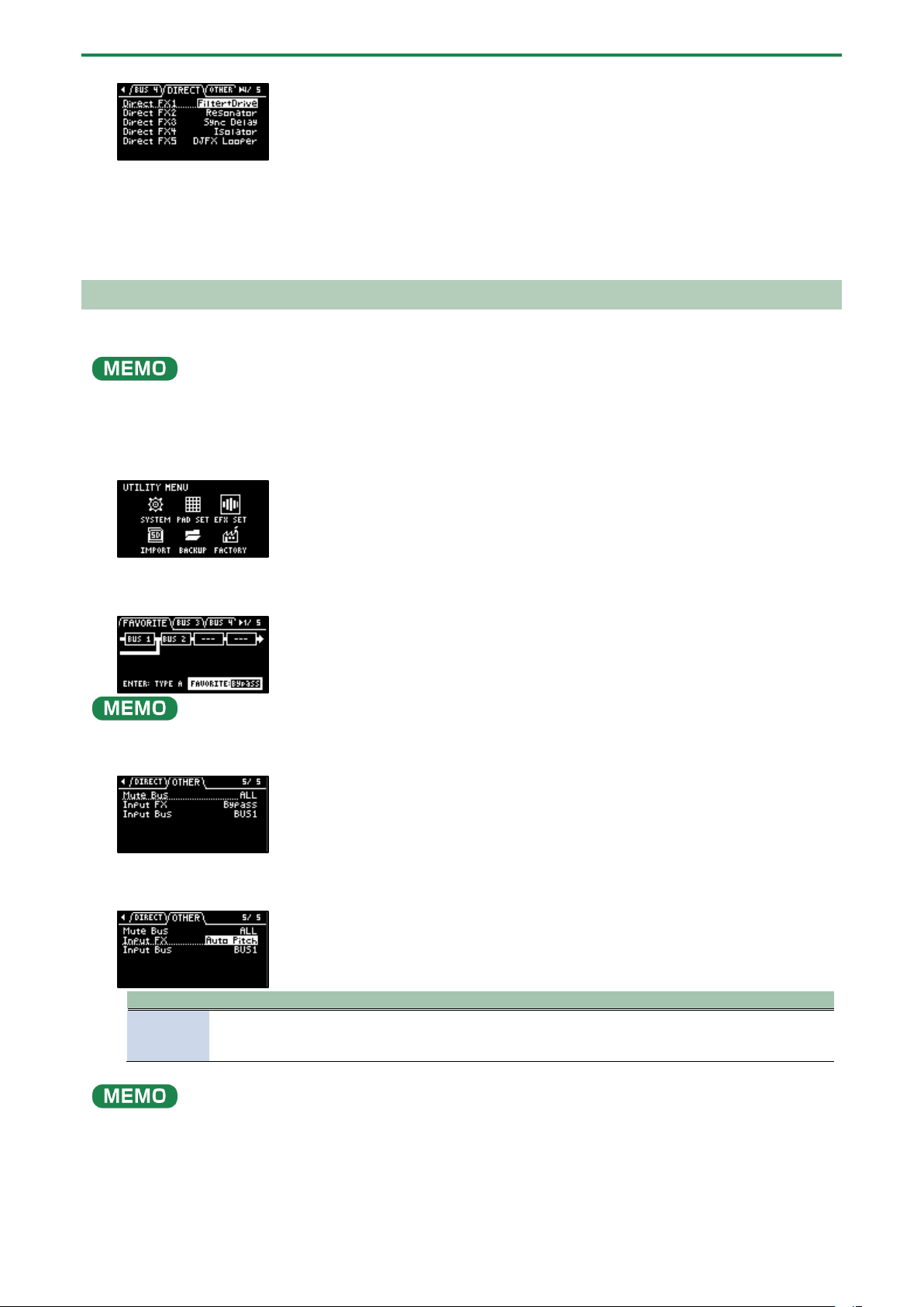
Configuring the Various Settings (UTILITY)
112
6.
Use the [VALUE] knob to select the effect, and press the [VALUE] knob.
The effect is assigned to the effect button you selected. After this, you can use the effect buttons on the top panel to switch
the assigned effects on/off.
7.
To finish making settings, press the [EXIT] button.
Configuring the Input Effects (INPUT FX)
The INPUT FX (input effects) are effects used only for the input jacks. You can apply effects to the audio that’s inputted to this unit.
These are the same parameters as the “INPUT FX parameters”, which are used for sampling and resampling.
1.
Hold down the [SHIFT] button and press the pad [13].
The UTILITY MENU screen appears.
2.
Use the [VALUE] knob to select “EFX SET”, and press the [VALUE] knob.
The effect setting screen appears.
From the top screen, you can also make this screen appear by pressing pad [16] while holding down the [SHIFT] button.
3.
Turn the [CTRL 3] knob to select “OTHER”.
4.
Use the [VALUE] knob to move the cursor to “Input FX”, and press the [VALUE] knob.
The value display is highlighted, and you can now change the effects.
Parameter
Value
EFX Type
Bypass, Auto Pitch(*), Vocoder(*), Harmony(*), Gt Amp Sim(*), Chorus, JUNO Chorus, Reverb, TimeCtrlDly,
Chromatic PS, Downer, WrmSaturator, 303 VinylSim, 404 VinylSim, Cassette Sim, Lo-fi, Equalizer,
Compressor
●
Effects marked with an (*) are for INPUT FX only.
● For details on the various effect parameters, refer to “MFX List(P.129)”.
5.
Use the [VALUE] knob to select the effect, and press the [VALUE] knob.
This sets the effect.
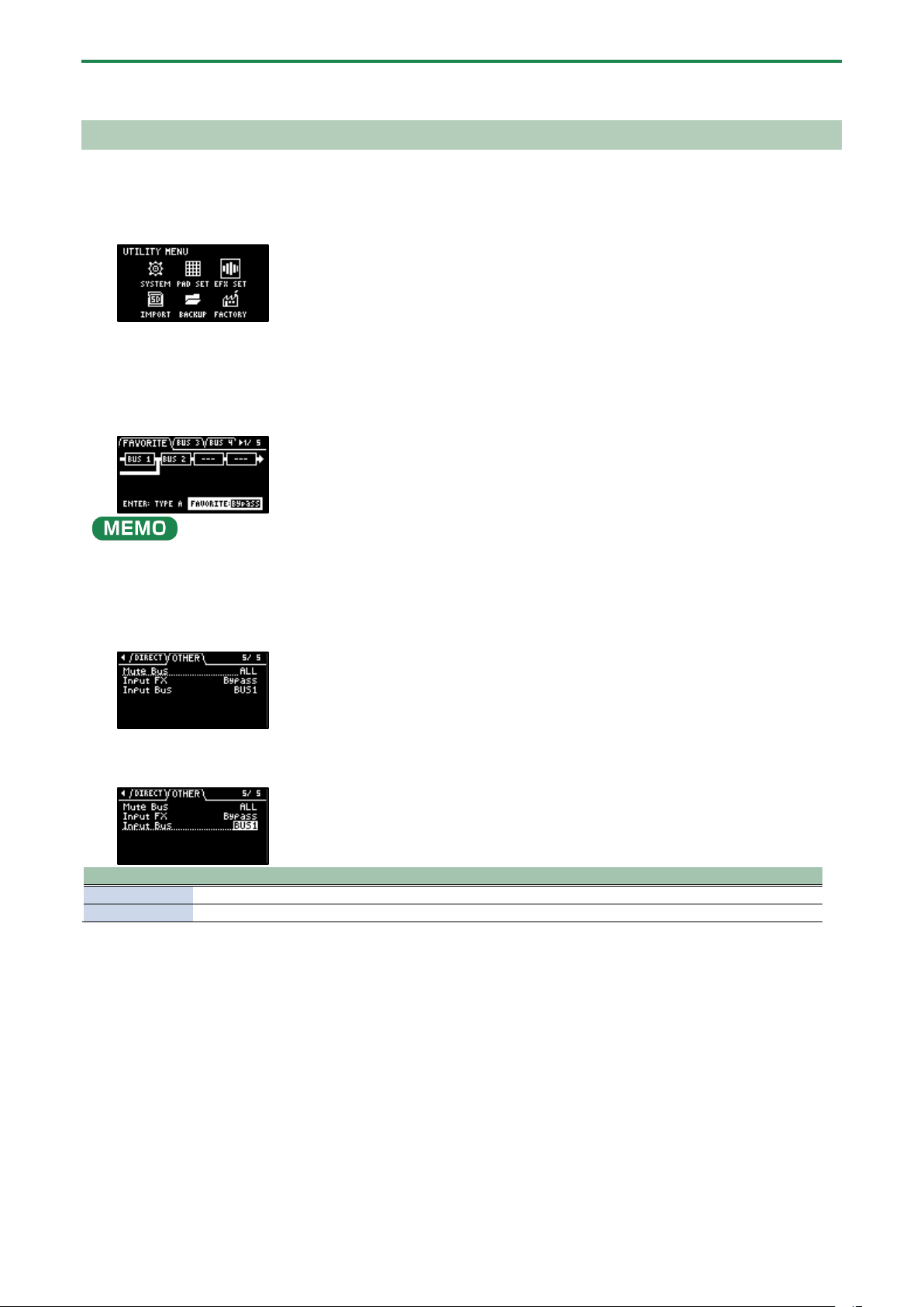
Configuring the Various Settings (UTILITY)
113
6.
To finish making settings, press the [EXIT] button.
Sending the Audio Input from the INPUT Jack to a Bus
You can set the bus to which the playback audio signals coming into the INPUT jack are sent (meaning which effects are used).
1.
Hold down the [SHIFT] button and press the pad [13].
The UTILITY MENU screen appears.
2.
Use the [VALUE] knob to select “EFX SET” and press the [VALUE] knob.
The effect setting screen appears.
From the top screen, you can also make this screen appear by pressing pad [16] while holding down the [SHIFT] button.
3.
Turn the [CTRL 3] knob to select “OTHER”.
4.
Use the [VALUE] knob to move the cursor to “Input Bus” and press the [VALUE] knob.
The displayed value is highlighted, and you can now edit the Input Bus.
Value
Explanation
DRY
The signal is not sent to BUS 1, BUS 2 (the BUS 1 and BUS 2 effects are not used).
BUS1, BUS2
The signal is sent to BUS 1 or BUS 2. The effects set for BUS 1 and BUS 2 are used.
5.
Use the [VALUE] knob to select the bus, and press the [VALUE] knob.
This confirms the bus to which the input audio is sent.
6.
To finish making settings, press the [EXIT] button.

Configuring the Various Settings (UTILITY)
114
Importing/Exporting (Using the SD Card)
Using a SD card lets you import the samples you like into the SP-404MK2, or exchange patterns and other data between different
SP-404MK2 units.
To work with data on the SD card, the SD card folder structure must be set up as shown below.
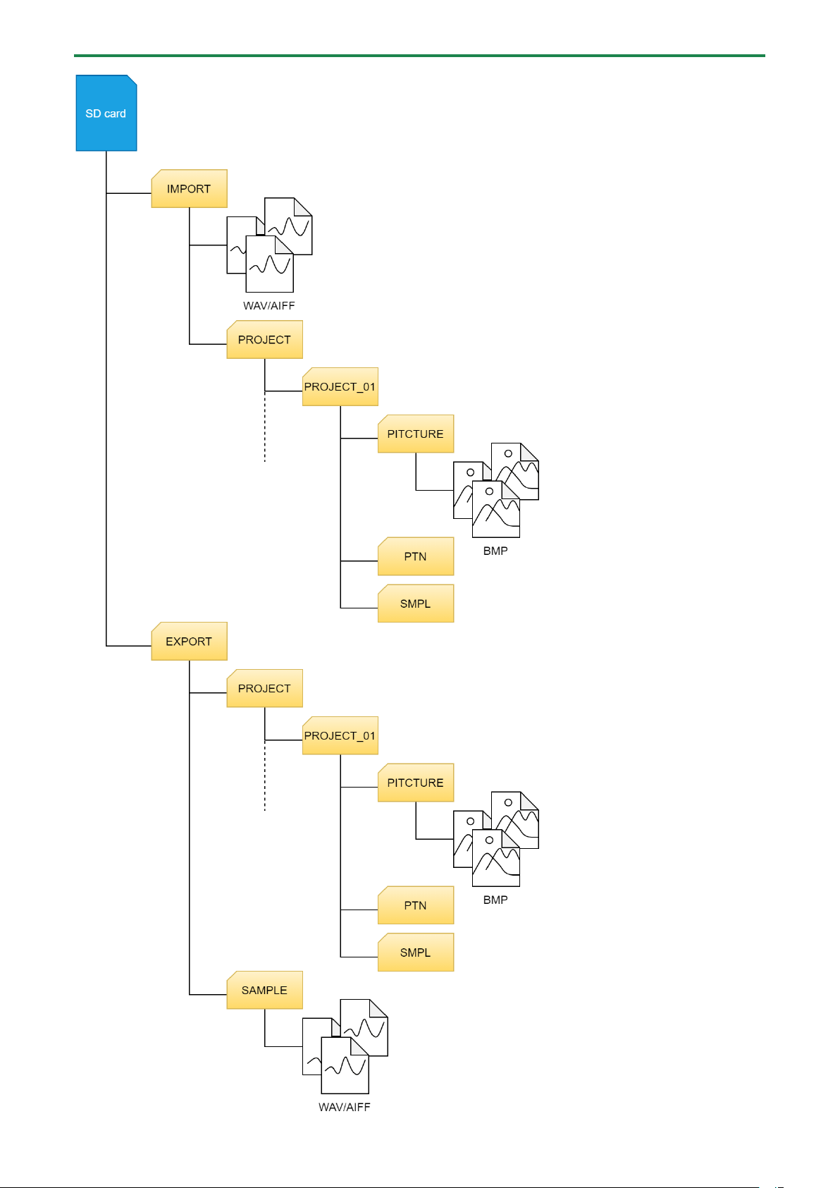
Configuring the Various Settings (UTILITY)
115
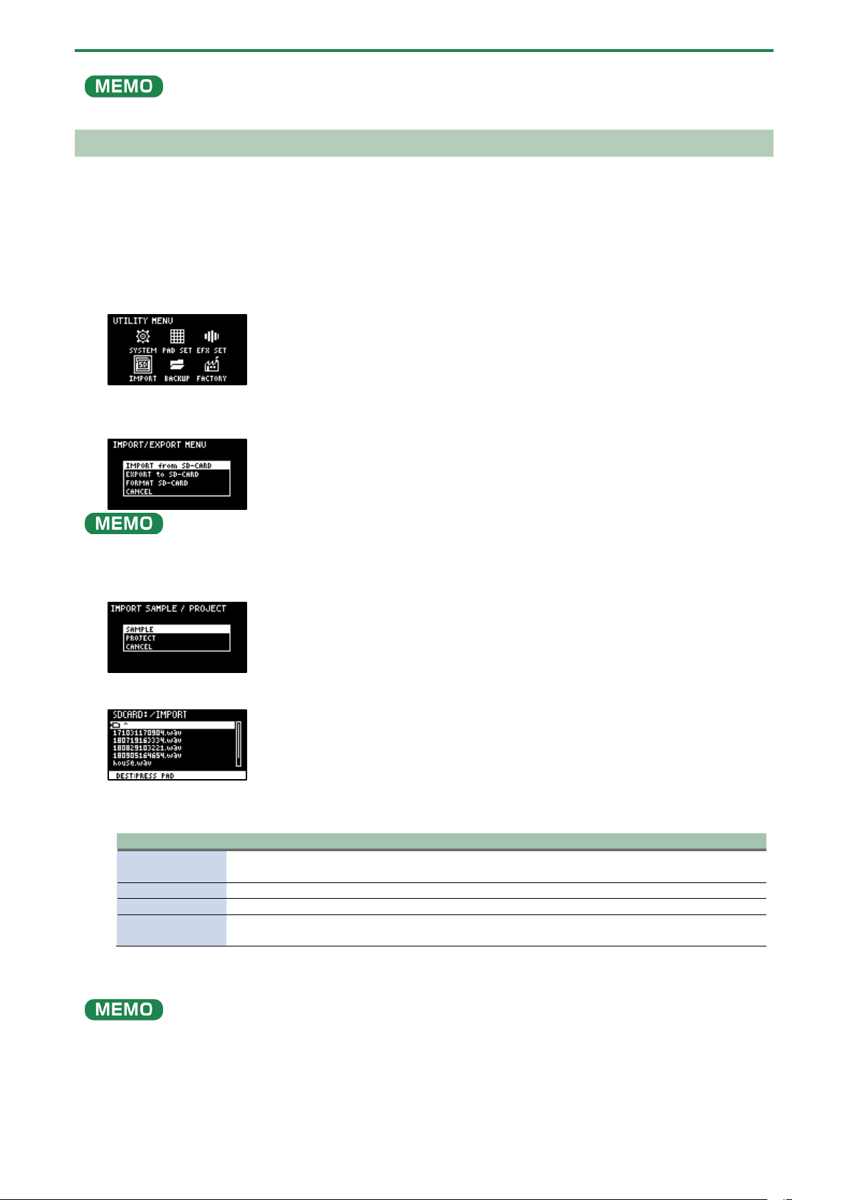
Configuring the Various Settings (UTILITY)
116
Some memory card types or memory cards from some manufacturers may not record or play back properly on the unit.
Importing Samples (IMPORT SAMPLE)
You can import commercially available audio material or audio material created on your computer from an SD card.
1.
Using your computer or similar device, save the samples you wish to import to the “IMPORT” folder on
the SD card (
Importing/Exporting (Using the SD Card)(P.114)).
2.
Insert the SD card on which the samples are saved into the SD card slot of this unit.
3.
Hold down the [SHIFT] button and press the pad [13].
The UTILITY MENU screen appears.
4.
Use the [VALUE] knob to select “IMPORT,” and press the [VALUE] knob.
The IMPORT/EXPORT MENU screen appears.
From the top screen, you can also make this screen appear by pressing pad [14] while holding down the [SHIFT] button.
5.
Use the [VALUE] knob to select “IMPORT from SD-CARD,” and press the [VALUE] knob.
The IMPORT SAMPLE / PROJECT screen appears.
6.
Use the [VALUE] knob to select “SAMPLE,” and press the [VALUE] knob.
7.
Press pads [1]–[16] to select the pad to which you want to assign the imported sample.
Normally, you should select a pad that’s blinking yellow (an empty pad).
Pad status
Explanation
Unlit (dark
orange)
Sample is already assigned to the pad
Blinking yellow
Sample not yet assigned to the pad (empty pad)
Blinking red
Imported sample assigned to the pad (import destination pad)
Lit red
Imported sample assigned to the pad (overwrite and import to a pad that already has a sample
assigned to it)
8.
Use the [VALUE] knob to select the sample to import, and press the [VALUE] knob.
The samples are imported and assigned to the selected pads.
●
You can preview the samples when you turn the [VALUE] knob to select a sample (this is the automatic preview function).
You can also preview the sample by pressing the [SUB PAD] button.
● When selecting samples inside a folder, use the [VALUE] knob to select the folder, and then press the [VALUE] knob.
● Hold down the [SHIFT] button and turn the [VALUE] knob to select multiple samples.
● Hold down the [MARK] button and turn the [VALUE] knob to quickly scroll through the list of samples.
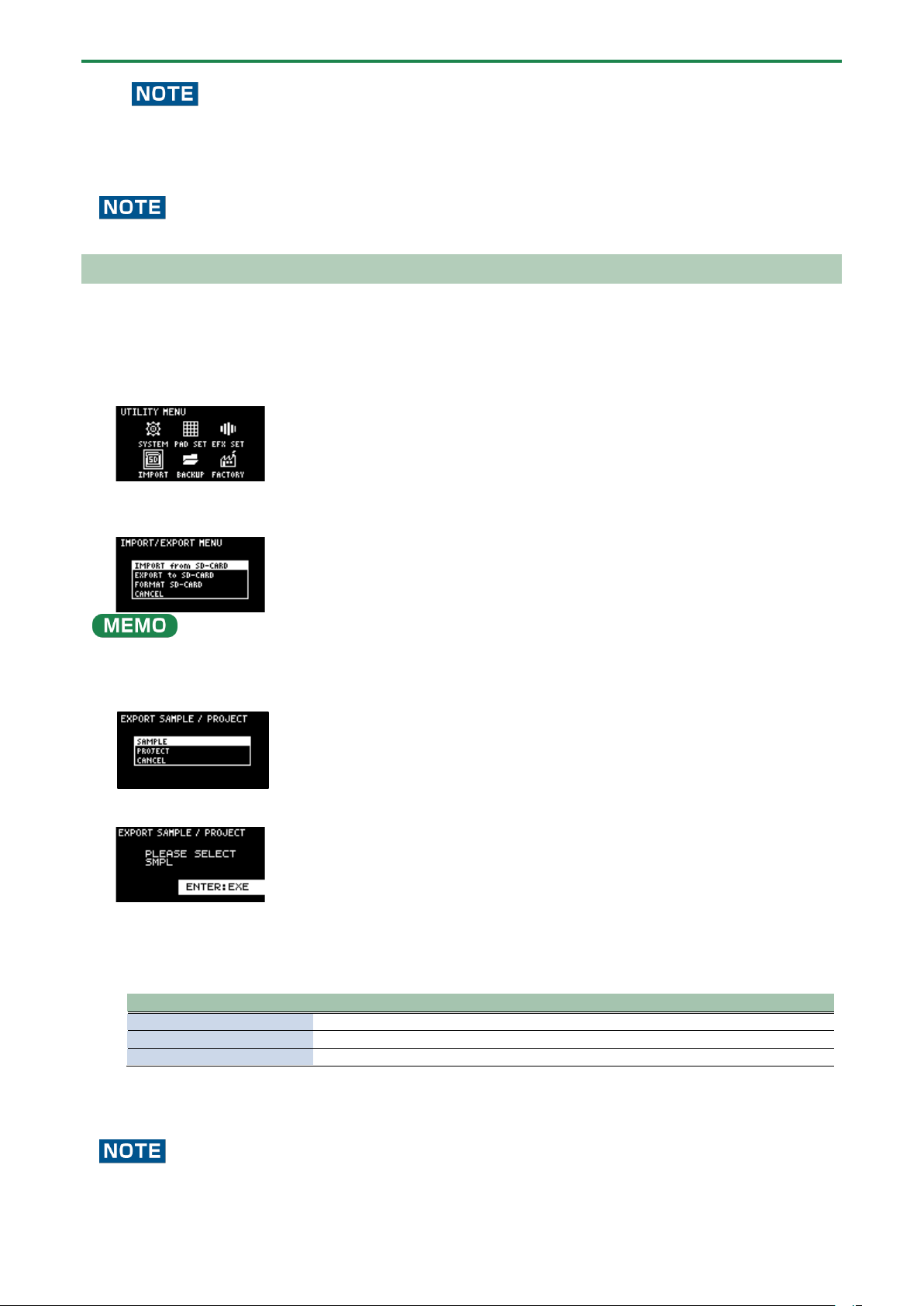
Configuring the Various Settings (UTILITY)
117
When importing a sample to a pad that already has an assigned sample (pads that are lit up red), a confirmation message
appears, asking if you want to overwrite the sample.
To overwrite the sample and import a new sample, turn the [VALUE] knob to select “OK,” and press the [VALUE] knob.
Performing this operation overwrites (erases) the sample in the copy destination pad.
Never turn off the power or remove the SD card while the screen indicates “Working...”
Exporting Samples (EXPORT SAMPLE)
You can export the samples to an SD card to use on your computer or on a different SP-404MK2.
1.
Insert the SD card to which the samples are to be exported into the SD card slot of this unit.
2.
Hold down the [SHIFT] button and press the pad [13].
The UTILITY MENU screen appears.
3.
Turn the [VALUE] knob to select “IMPORT”.
The IMPORT/EXPORT MENU screen appears.
From the top screen, you can also make this screen appear by pressing pad [14] while holding down the [SHIFT] button.
4.
Use the [VALUE] knob to select “EXPORT to SD-CARD”, and press the [VALUE] knob.
The EXPORT SAMPLE / PROJECT screen appears.
5.
Use the [VALUE] knob to select “SAMPLE”, and press the [VALUE] knob.
6.
Press the pads of samples that you want to export to the SD card.
The pads light up orange. You can also select multiple samples (pads) to export. When doing so, press a pad again if you
want to deselect its sample for export (the pad blinks orange).
Pad status
Explanation
Unlit (dark orange)
Sample not yet assigned to the pad (empty pad)
Blinking orange
Sample is already assigned to the pad
Lit orange
Pad with a sample to export to the SD card (pad to export)
7.
Select the samples to export and press the [VALUE] knob.
The selected samples are saved in the “EXPORT SAMPLE” folder of the SD card (Importing/Exporting (Using the SD
Card)(P.114)).
Never turn off the power or remove the SD card while the screen indicates “Working...”.
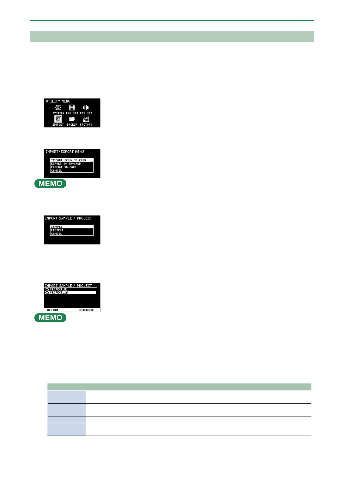
Configuring the Various Settings (UTILITY)
118
Importing a Project (IMPORT PROJECT)
You can import a project into this unit that was created on a different SP-404MK2 and exported to an SD card.
1.
Follow the steps in “Exporting a Project (EXPORT PROJECT)(P.119)” to export the project(s) to an SD card.
2.
Insert the SD card on which the projects are saved into the SD card slot of this unit.
3.
Hold down the [SHIFT] button and press the pad [13].
The UTILITY MENU screen appears.
4.
Turn the [VALUE] knob to select “IMPORT”.
The IMPORT/EXPORT MENU screen appears.
From the top screen, you can also make this screen appear by pressing pad [14] while holding down the [SHIFT] button.
5.
Use the [VALUE] knob to select “IMPORT from SD-CARD”, and press the [VALUE] knob.
The IMPORT SAMPLE / PROJECT screen appears.
6.
Use the [VALUE] knob to select “PROJECT”, and press the [VALUE] knob.
7.
Press the [ROLL] button.
The contents of the “EXPORT” folder are shown. The contents of the project folder (PROJECT_**) that was exported to the SD
card are shown.
●
The contents of the “IMPORT” folder are shown first on the screen where you select the project to import. Each time you
press the [ROLL] button, the view switches between the “IMPORT” and “EXPORT” folders.
● From your computer, you can select the project to export from the “IMPORT” folder list screen.
1.
Open the SD card on your computer.
2.
Move the exported project folder (PROJECT_**) from the “EXPORT” folder to the “IMPORT” folder
(Importing/Exporting (Using the SD Card)(P.114)).
8.
Press pads [1]–[16] to select the project number to import.
Normally, you should select a pad that’s blinking yellow (an empty pad).
Pad status
Explanation
Unlit (dark
orange)
Project number that already contains a project
Blinking
yellow
Project number for which a project hasn’t been created (empty project)
Blinking red
Project number to which the imported project is saved
Lit red
Project number to which the imported project is saved (if a project already exists at that project
number, it is overwritten with the newly imported project)
9.
Turn the [VALUE] knob to select the project to import, and press the [VALUE] knob.
The project is now imported.
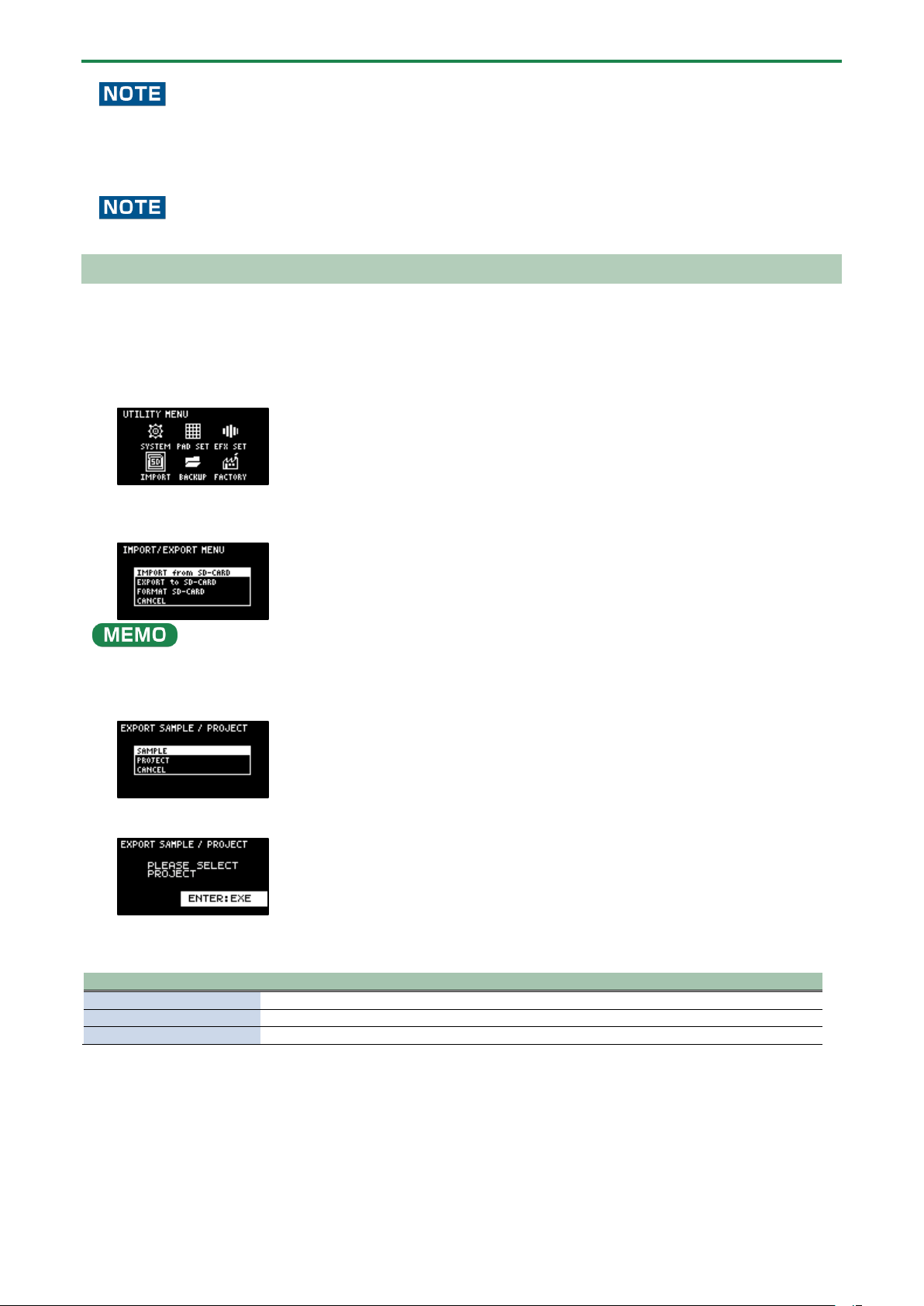
Configuring the Various Settings (UTILITY)
119
When you import a project to a project number that already contains a project (the pad lights up red), a message is shown to
confirm the overwrite-save.
To import and overwrite, turn the [VALUE] knob to select “OK”, and press the [VALUE] knob.
Performing this operation overwrites (erases) the project in the import destination.
Never turn off the power or remove the SD card while the screen indicates “Working...”.
Exporting a Project (EXPORT PROJECT)
You can export projects to an SD card if you want to use them on another SP-404MK2.
1.
Insert the SD card to which the samples are to be exported into the SD card slot of this unit.
2.
Hold down the [SHIFT] button and press the pad [13].
The UTILITY MENU screen appears.
3.
Turn the [VALUE] knob to select “IMPORT”.
The IMPORT/EXPORT MENU screen appears.
From the top screen, you can also make this screen appear by pressing pad [14] while holding down the [SHIFT] button.
4.
Use the [VALUE] knob to select “EXPORT to SD-CARD”, and press the [VALUE] knob.
The EXPORT SAMPLE / PROJECT screen appears.
5.
Use the [VALUE] knob to select “PROJECT”, and press the [VALUE] knob.
6.
Press the pads of the projects that you want to export to the SD card.
The pads light up orange.
Pad status
Explanation
Unlit (dark orange)
Pad for which a project hasn’t been created (empty pad)
Blinking orange
Pad for which a project has been created
Lit orange
Pad containing a project to be exported to SD card (pad to export)
You can also select multiple projects (pads) to export. When doing so, if you decide not to export a certain project, press its
pad again to deselect it (the pad blinks orange).
7.
After you’ve selected the projects to export, press the [VALUE] knob.
The selected projects are saved in the “EXPORT PROJECT” folder of the SD card (Importing/Exporting (Using the SD
Card)(P.114)).
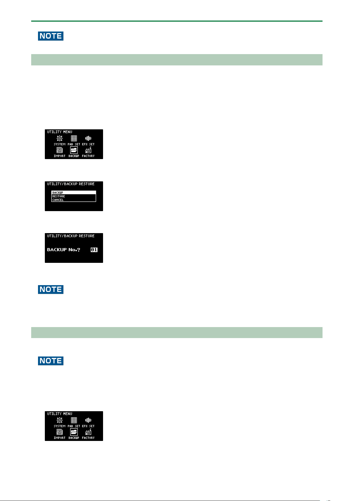
Configuring the Various Settings (UTILITY)
120
Never turn off the power or remove the SD card while the screen indicates “Working...”.
Backing up Your Data (BACKUP)
By backing up the data on this unit, you can transfer your data to another SP-404MK2 or restore your data in the event that
something happens to it.
You can save up to 64 sets of backup data to a single SD card (note that this depends on the SD card’s capacity).
1.
Insert the SD card on which the backup data is to be saved into the SD card slot of this unit.
2.
Hold down the [SHIFT] button and press the pad [13].
The UTILITY MENU screen appears.
3.
Use the [VALUE] knob to select “BACKUP”, and press the [VALUE] knob.
The UTILITY / BACKUP RESTORE screen appears.
4.
Use the [VALUE] knob to select “BACKUP”, and press the [VALUE] knob.
The backup number selection screen appears.
5.
Use the [VALUE] knob to select a backup number (01–64), and press the [VALUE] knob.
The backup data is saved to the SD card.
If there is already backup data on the SD card with the same number, a message appears that confirms whether you want to
overwrite.
To import and overwrite, turn the [VALUE] knob to select “OK”, and press the [VALUE] knob.
When this operation is executed, the backup data on the SD card that has the same number is overwritten (erased).
Restoring from Backup Data (RESTORE)
You can use the backup data that you created with the backup function to restore the data to the SP-404MK2.
Note that once you restore data on this unit from the backup data, all data that was saved on this unit is erased (overwritten).
To save the data of this unit, use the backup function to make a backup.
1.
Insert the SD card on which the backup data is saved into the SD card slot of this unit.
2.
Hold down the [SHIFT] button and press the pad [13].
The UTILITY MENU screen appears.
3.
Use the [VALUE] knob to select “BACKUP”, and press the [VALUE] knob.
The UTILITY / BACKUP RESTORE screen appears.
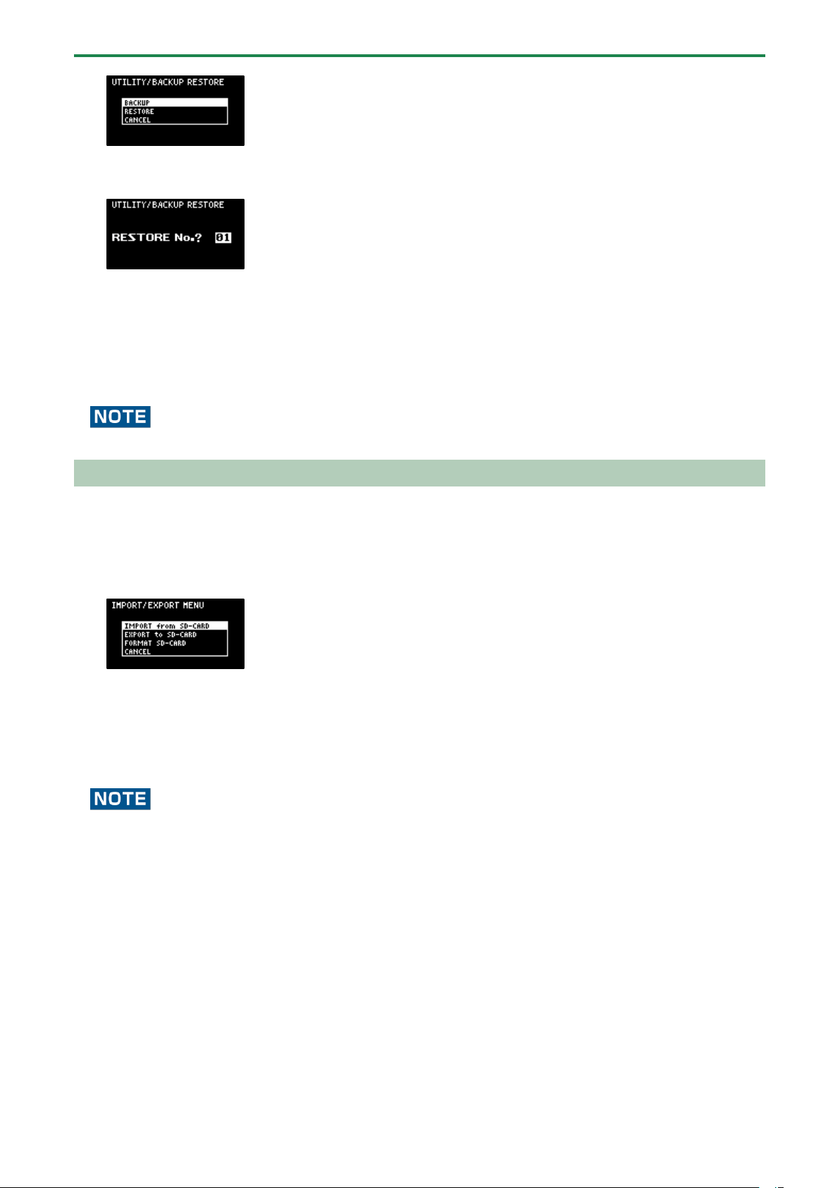
Configuring the Various Settings (UTILITY)
121
4.
Use the [VALUE] knob to select “RESTORE”, and press the [VALUE] knob.
The backup number selection screen appears.
5.
Use the [VALUE] knob to select a backup number which you want to restore (01–64), and press the
[VALUE] knob.
A confirmation message appears, asking if you want to overwrite.
6.
To overwrite the existing data and restore the backup data, turn the [VALUE] knob to select “OK”, and
press the [VALUE] knob.
This restores the backup data to this unit.
Never turn off the power or remove the SD card while the screen indicates “Working...”.
Formatting an SD Card
To use an SD card with this unit, you must first format (initialize) it on the unit.
1.
Insert the SD card into the SD card slot.
2.
Hold down the [SHIFT] button and press the pad [14].
The IMPORT/EXPORT MENU screen appears.
3.
Use the [VALUE] knob to select “FORMAT SD-CARD”, and press the [VALUE] knob.
A confirmation message appears.
If you decide to cancel, press the [EXIT] button.
4.
Use the [VALUE] knob to select “OK”, and press the [VALUE] knob.
The SD card is now formatted. When formatting is complete, the screen indicates “Operation Completed!”.
Never turn off the power or remove the SD card while the screen indicates “Working...”.
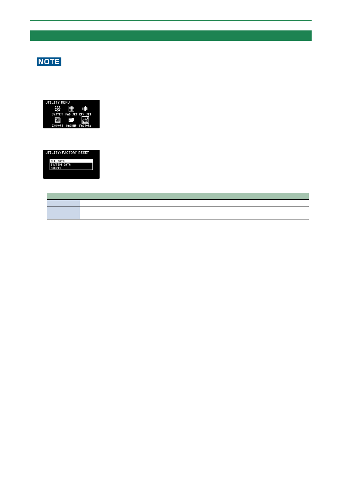
Configuring the Various Settings (UTILITY)
122
Restoring the Factory Settings (FACTORY RESET)
This operation restores the sample and pattern data as well as the system settings saved on this unit to their factory defaults.
Doing this causes all data saved on this unit to be lost.
To save the data of this unit, use the backup function to make a backup (Backing up Your Data (BACKUP)(P.120)).
1.
Hold down the [SHIFT] button and press the pad [13].
The UTILITY MENU screen appears.
2.
Use the [VALUE] knob to select “FACTORY”, and press the [VALUE] knob.
The UTILITY / FACTORY RESET screen appears.
3.
Turn the [VALUE] knob to select the data to initialize, and press the [VALUE] knob to confirm.
Value
Explanation (data to initialize)
ALL DATA
This initializes all data. The samples and patterns are restored to the factory default data.
SYSTEM
DATA
This restores the settings for the system parameters and effect parameters to their factory defaults. This
has no effect on the samples and patterns.
A confirmation message appears, asking if you want to initialize the data.
4.
If you wish to initialize, turn the [VALUE] knob to select “OK”, and press the [VALUE] knob.
The message “Please Power OFF” appears.
5.
Turn this unit’s power off, and then on again.
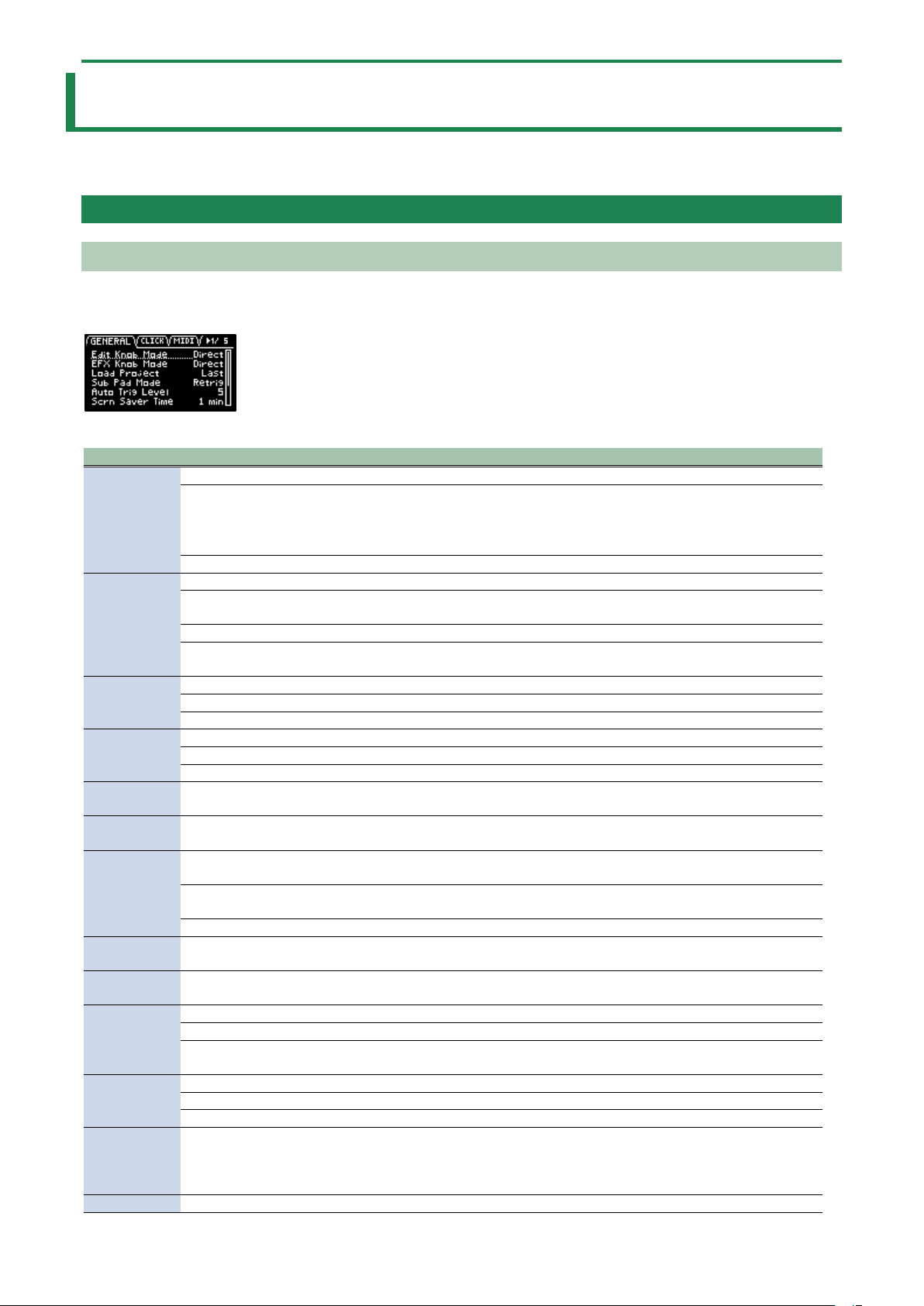
Appendix
123
Appendix
Parameter Guide
SYSTEM
GENERAL
Parameter
Value
Explanation
Edit Knob
Mode
This sets how the values change when you move the knobs.
CATCH
When you move a knob, control data is only outputted when the position of the knob
reaches or “catches up” to the value of its internal parameter.
● In “Mixing the Samples (DJ MODE)(P.87)”, the knobs work in CATCH mode,
regardless of the settings.
DIRECT
When you move a knob, the control data (current position) is always outputted.
EFX Knob
Mode
This sets how the values change when you move the knobs.
CATCH
When you move a knob, control data is only outputted when the position of the knob
reaches or “catches up” to the value of its internal parameter.
DIRECT
When you move a knob, the control data (current position) is always outputted.
Manual
When you switch effects, control data corresponding to the position of the knob is
outputted.
Load Project
This sets the project that loads when the unit starts up.
Last
Loads the project that was used right before the power was last turned off.
1–16
Loads a specified project.
Sub Pad
Mode
This sets the functionality of the [SUB PAD] button in sample mode.
Retrig
Retriggers the current pad (plays its sound again).
SkipBack
Switches to skip-back mode.
Auto Trig
Level
1–10
Sets the level at which note input is detected (the level at which sampling
automatically starts, and the level at which recording to the skip-back memory begins).
Scrn Saver
Time
1, 5, 10 (min)
Sets the time before the screen saver starts (in minutes).
Scrn Saver
Type
OldRave,
Naminori
Selects the type of screen saver.
Custom
When you select “Custom”, you can use an image file that you’ve imported as the
screen image for the screen saver (Customizing the Screen Saver(P.104)).
Disp Off
Select “Disp Off” to turn off the display.
BPM Auto
Dtct
ON, OFF
When this is set to “ON”, the tempo (BPM) is automatically detected when you import a
sample.
BPM Detect
Range
100-199, 80-159,
70-139, 50-99
Selects the range at which the tempo (BPM) of a sample is automatically detected.
Pad Mute
When Pad Mute is on, this selects whether to monitor the muted samples.
Mst+Phn
Muted samples are not outputted to any jack.
Master
Muted samples can be output (monitored) from the PHONES jack. In this case, no
effects are applied.
PTN Change
Mode
This sets how the samples play back when switching between patterns during pattern playback.
MKII
Sample playback stops when the pattern changes.
SX
Sample playback continues when the pattern changes.
Pop-up Time
Normal, Short,
OFF
Sets how long the popup screens are displayed.
Set this to “Short” to make the popup screens display for a shorter time than the
“Normal” setting.
Set this to “OFF” if you don’t want popups to display.
SBS Time
Sets the recording time for skip-back memory.
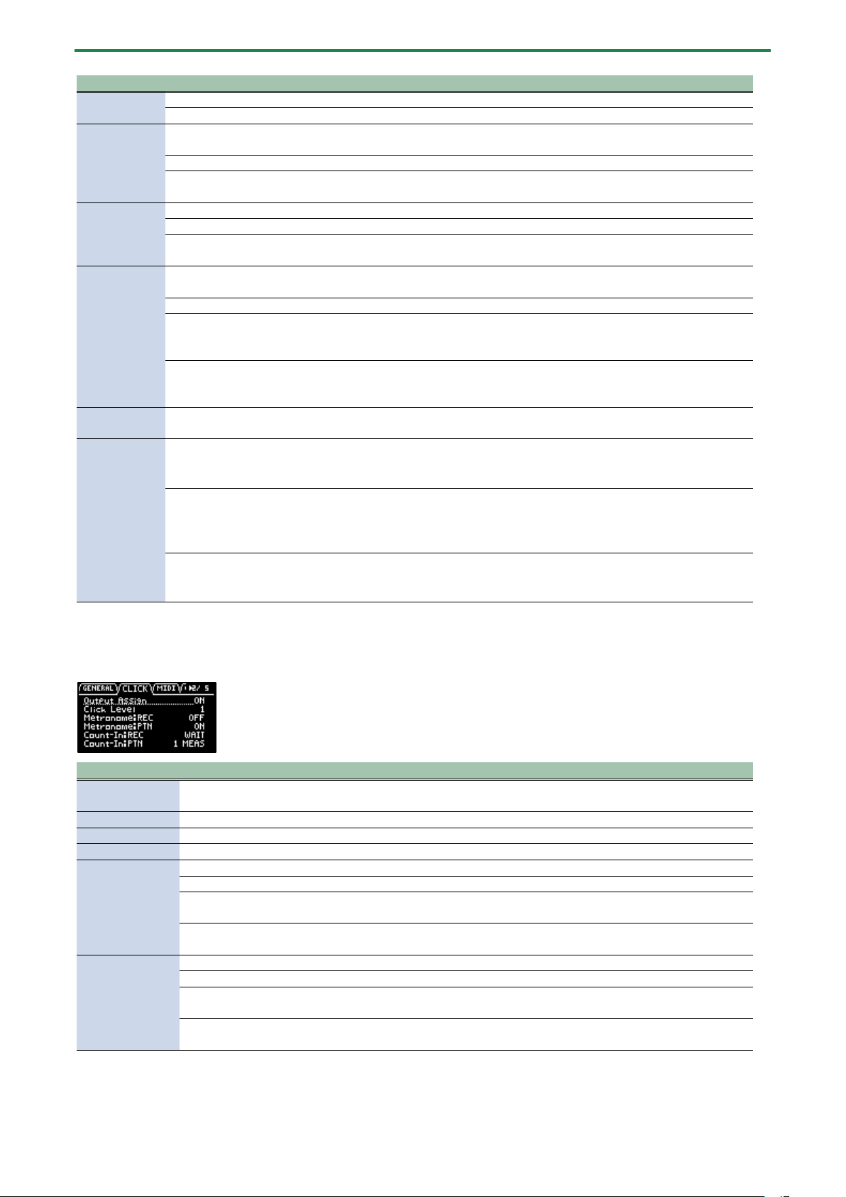
Appendix
124
Parameter
Value
Explanation
Def
Recording time: 25 sec (max.)
Long
Recording time: 40 sec (max.)
Reverse Type
This selects the point (time) at which reverse playback begins when you press the [REVERSE] button during
sample playback.
404
Starts reverse playback at the sample’s end point. This works the same as the SP-404SX.
303
Starts reverse playback immediately from the playback position of the current sample.
This works the same as the SP-303.
USB IN
This selects where the audio signal input from the USB port is sent.
LINE IN
Mixes the USB audio signal with the audio signal from the LINE IN jacks.
MIX OUT
Mixes the USB audio signal with the MIXER output, without going through the INPUT
FX or BUS FX.
DJ mode TS
type
This lets you change how the audio is processed when changing the playback speed of a sample in DJ
mode.
VINYL
Changes the playback speed and pitch at the same time, like an analog record.
BACKING
Independently controls the playback speed and pitch.
Processes the sound as appropriate for musical instruments whose sounds have a
noticeable decay.
ENSEMBLE
Independently controls the playback speed and pitch.
Processes the sound as appropriate for musical instruments that have a sustaining
sound.
Bend Sens
(DJ)
10–200
Sets how quickly the pitch of a sample changes when you press the [BEND-] and
[BEND+] pads.
FileSystem
Selects the character code for filenames that can be recognized by this unit when you import a sample.
● The unit must be restarted once you’ve changed the settings and pressed the [EXIT] button to exit the
SYSTEM screen.
Multi-Byte
Letters, numbers, symbols, double-byte characters (kanji, hiragana, katakana)
● This lets the unit recognize and import files with filename that use double-byte
and similar characters. Note that this unit doesn’t correctly display double-byte
characters, and these characters appear garbled.
Latin1
Letters, numbers, symbols
● With this setting, files with double-byte characters in their filenames can’t be
recognized by this unit.
CLICK
Parameter
Value
Explanation
Output Assign
OFF, ON
When this is set to ON, the metronome sound is output from the LINE OUT jacks and from
the USB port.
Click Level
1–5
Sets the volume of the metronome.
Metronome:REC
OFF, ON
When this is ON, the metronome sound is output while you are sampling or resampling.
Metronome:PTN
OFF, ON
When this is ON, the metronome sound is output when a pattern is being recorded.
Count-In:REC
This selects how sampling or resampling starts.
OFF
Sampling or resampling starts at the same time that you press the [REC] button.
1 MEAS, 2
MEAS
When you press the [REC] button, a count-in begins one or two measures before where
sampling or resampling begins.
WAIT
Sampling or resampling starts when you press a pad to play back a sample, or when
audio is detected from an external device.
Count-In:PTN
This selects how pattern recording begins.
OFF
Pattern recording starts at the same time that you press the [REC] button.
1 MEAS, 2
MEAS
When you press the [REC] button, a count-in of one or two measures begins before
pattern recording starts.
WAIT
Pattern recording starts when you press a pad to play back a sample, or when audio is
detected from an external device.
MIDI
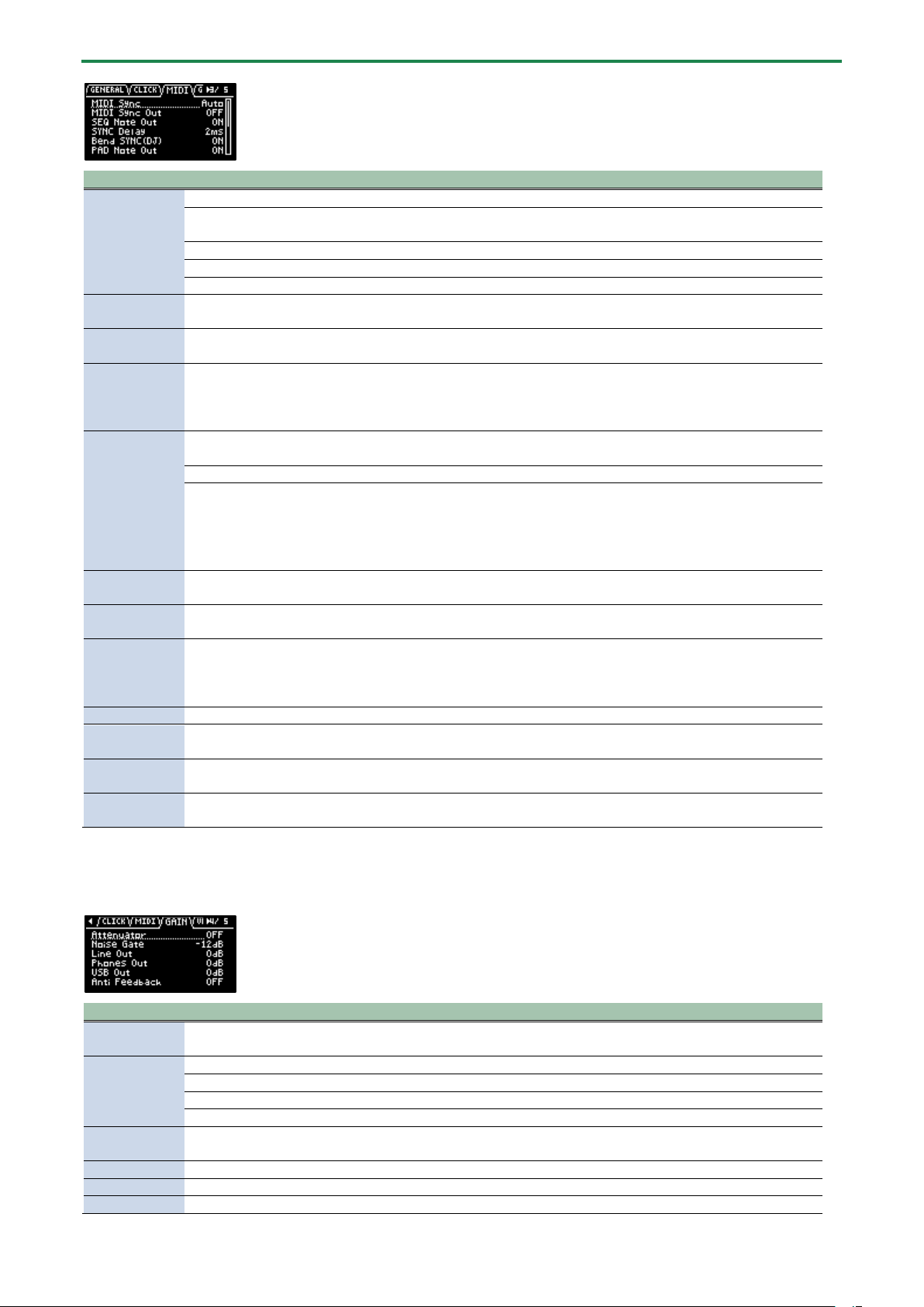
Appendix
125
Parameter
Value
Explanation
MIDI Sync
Specifies the tempo source.
Auto
The tempo automatically synchronizes to the MIDI clocks if MIDI clocks are input via the
MIDI IN connector or the USB port.
Internal
The tempo specified on this unit is used.
MIDI
The tempo synchronizes to the MIDI clocks received via the MIDI IN connector.
USB
The tempo synchronizes to the MIDI clocks received via the USB port.
MIDI Sync Out
OFF, ON
When this is ON, clocks, start and stop are transmitted to the device connected to this
unit’s MIDI OUT connector.
SEQ Note Out
OFF, ON
When this is set to “ON”, the note number corresponding to the pattern (pad) is output via
the MIDI OUT connector when the pattern plays back.
SYNC Delay
0–20ms
Adjust this if there is a delay (latency) in sound between your external MIDI device and this
unit.
Larger values make this unit play back at a more delayed timing.
When this is set to “0”, this unit plays and outputs MIDI messages with the same timing.
Bend
SYNC(DJ)
This sets how the MIDI clock output from this unit changes when you press the [BEND-] or [BEND+] pads to
change the playback speed of this unit.
OFF
MIDI clocks are output at a fixed rate.
ON
MIDI clocks outputted from this unit are synchronized with this unit’s playback speed.
With this setting, the tempo of MIDI devices connected externally changes in time with the
playback speed of this unit.
● If you press the [BEND-] [BEND+] pads while holding down the [REMAIN] button, the
MIDI clocks do not change (the effect is the same as the OFF setting).
PAD Note Out
OFF, ON
When this is set to “ON”, note numbers corresponding to the pads are output via the MIDI
OUT connector when you play the pads.
Soft Through
OFF, ON
If this is “ON”, MIDI messages that are input to the MIDI IN connector are output to the MIDI
OUT connector.
USB-MIDI
Thru
OFF, ON
When this is “ON”, MIDI signals that are input via the USB port are output to the MIDI OUT
connector. MIDI signals that are inputted via the MIDI IN connector are also outputted to
the USB port.
The inputted MIDI signals are also transmitted to the internal sound module at that time.
PC Rx
OFF, ON
When this is ON, program change messages are received.
MIDI Mode
A, B
Changes the note number assignment according to the mode you’ve selected.
For details, refer to “MIDI Note Map(P.152).”
Pad MIDI
Channels
1/2, 2/3–
9/10, 10/11
Sets the offset value for the MIDI channel.
This setting is enabled when “MIDI Mode” is set to “B”.
Note offset
-11–35
Sets the offset value for the note number.
This setting is enabled when “MIDI Mode” is set to “B”.
GAIN
Parameter
Value
Explanation
Attenuator
OFF, ON
When this is ON, the gain of the audio input from the LINE IN jacks is lowered.
Turn the Attenuator on when the LINE IN input seems to be distorting.
Noise Gate
Reduces the noise floor in the signal input from the LINE IN and INPUT jacks.
OFF
The noise gate is not used.
-9dB, -12dB, -18dB
Reduces the noise floor at the specified level.
-Inf
Reduces the noise floor to the bare minimum.
Anti Feedback
OFF, ON
When this is “ON”, the anti-feedback function is enabled for the mic input.
This helps prevent mic feedback.
LINE OUT
0, +6, +12 (dB)
Sets the gain of the audio output from the LINE OUT jacks.
PHONES OUT
-18, -12, -6, 0, +6, +12 (dB)
Sets the gain of the audio output from the PHONES OUT jacks.
USB OUT
-24, -12, 0 (dB)
Sets the gain of the audio output from the USB port.
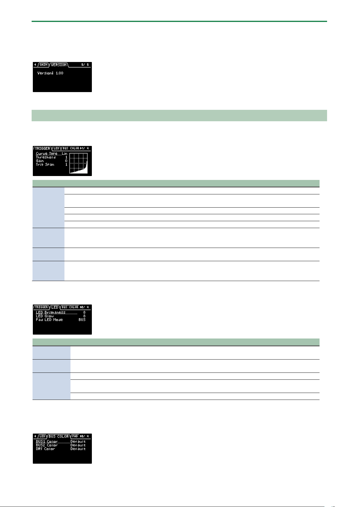
Appendix
126
VERSION
Displays the version of this unit.
PAD SET
TRIGGER
Parameter
Value
Explanation
Curve
Type
Sets how the volume changes according to how hard you strike a pad.
Lin
This is the standard setting. This produces the most natural balance between playing dynamics and
volume change.
Exp
Compared to “Lin”, playing strongly produces a greater change in volume.
Log
Compared to “Lin”, playing softly produces a greater change in volume.
Fix
Sets the volume at a fixed level of 127.
Threshold
1–
100
This sets the minimum sensitivity of the pads, at which the trigger signal is received only when a pad
is struck with at least a certain amount of force (velocity). This can be used to prevent a pad from
sounding due to vibrations from other pads.
Gain
0–
100
The sensitivity is adjusted with the curve as-is. The larger the value, the greater the sensitivity is when
playing the pads.
Trig Span
1–10
Adjusts the sensitivity of the pads to repeated strikes. With lower values, the pads detect repeated
strikes within a shorter time interval. Set this value higher if you don’t want the pad to accidentally
detect repeated strikes.
LED
Parameter
Value
Explanation
LED
Brightness
1–10
Sets the brightness of the indicators on the buttons and pads. This sets the brightness when the
buttons or pads are highlighted.
LED Glow
1–10
Sets the brightness of the indicators on the buttons and pads. This sets the brightness when the
buttons or pads are not highlighted.
Pad LED
Mode
This selects the color of the pad illumination.
BUS
The pads light up in the color set in “BUS COLOR”.
In this mode, the pad colors change according to the bus through which the sample audio is sent.
PAD
The pads light up in the color set in “PAD COLOR”.
BUS COLOR
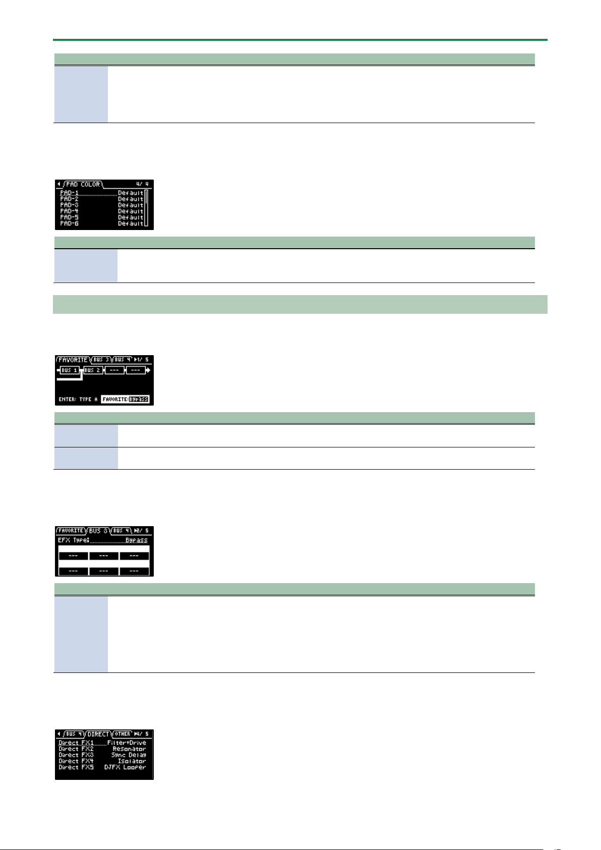
Appendix
127
Parameter
Value
Explanation
BUS1 Color
BUS2 Color
DRY Color
Default, 1–127,
White
Changes the pad color for each bus through which sample audio is sent.
This can be set for BUS 1, BUS 2 and DRY respectively.
This is enabled when Pad LED Mode is “BUS”.
● Hold down the [SHIFT] button and turn the [VALUE] knob to change the value in
steps of 10.
PAD COLOR
Parameter
Value
Explanation
PAD-1–PAD-
16
Default, 1–127,
White
Specifies the colors of individual pads.
This is enabled when Pad LED Mode is “PAD”, and when a sample is either playing back
or stopped while in sample mode.
EFX SET
FAVORITE
Parameter
Value
Explanation
Routing
TYPE A, TYPE B
Selects the routing (connection) of the bus to which effects are assigned.
“Configuring the Effect Routing(P.108)”
FAVORITE
1–16
Selects the combination of effects assigned to BUS 3 and BUS 4.
“Changing the Effects Assigned to BUS 3 and BUS 4(P.109)”
BUS 3, BUS 4
Parameter
Value
Explanation
EFX TYPE
Bypass, 303 VinylSim, 404 VinylSim, Cassette Sim, Lo-fi, Downer, Compressor,
Equalizer, Isolator, Super Filter, Filter+Drive, WrmSaturator, Overdrive, Distortion,
Crusher, Ring Mod, SBF, Resonator, Hyper-Reso, Chromatic PS, Reverb, Ha-Dou, Zan-
Zou, Sync Delay, TimeCtrlDly, Ko-Da-Ma, Tape Echo, Chorus, JUNO Chorus, Flanger,
Phaser, Wah, Slicer, Tremolo/Pan, To-Gu-Ro, DJFX Looper, Scatter, SX Reverb, SX
Delay, Cloud Delay
Selects the effects
assigned to BUS 3 or
BUS 4.
For details on the
parameters of each
effect, refer to “MFX
List(P.129)”.
DIRECT
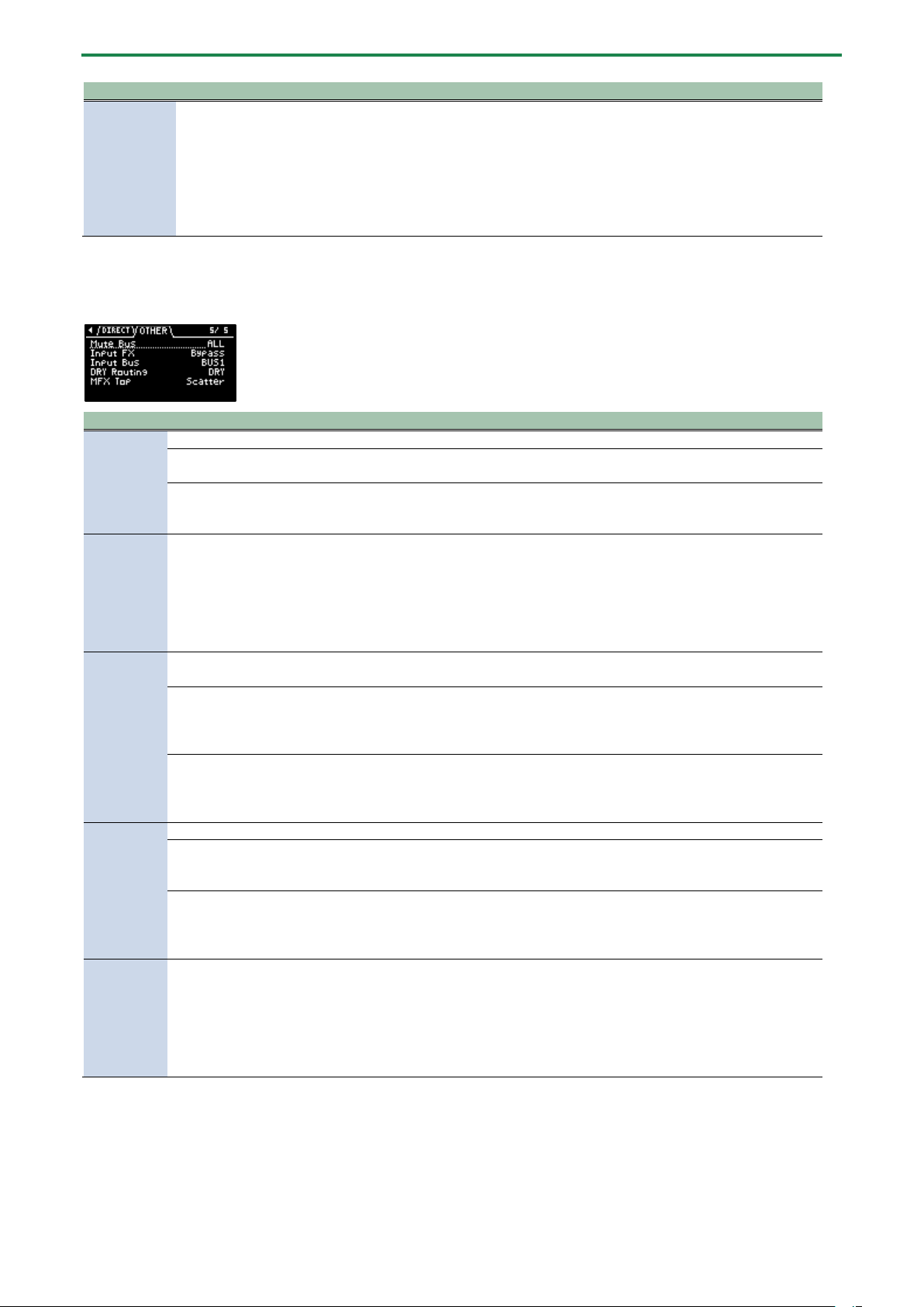
Appendix
128
Parameter
Value
Explanation
Direct FX1–
Direct FX5
Filter+Drive, Resonator, Sync Delay, Isolator, DJFX Looper, Scatter, Downer, Ha-
Dou, Ko-Da-Ma, Zan-Zou, To-Gu-Ro, SBF, Stopper, Tape Echo, TimeCtrlDly, Super
Filter, WrmSaturator, 303 VinylSim, 404 VinylSim, Cassette Sim, Lo-fi, Reverb,
Chorus, JUNO Chorus, Flanger, Phaser, Wah, Slicer, Tremolo/Pan, Chromatic PS,
Hyper-Reso, Ring Mod, Crusher, Overdrive, Distortion, Equalizer, Compressor, SX
Reverb, SX Delay, Cloud Delay, Back Spin
You can assign the
effects you like to the
effect buttons on the
top panel.
For details on the
parameters of each
effect, refer to “MFX
List(P.129)”.
OTHER
Parameter
Value
Explanation
Mute Bus
This individually selects the bus to mute with MUTE BUS.
ALL
Both BUS 1 and BUS 2
are muted.
BUS
Only the bus selected
with the [BUS FX] button
is muted.
Input FX
Bypass, Auto Pitch (*), Vocoder (*), Gt Amp Sim (*), Harmony (*), Chorus, JUNO
Chorus, Reverb, TimeCtrlDly, Chromatic PS, Downer, WrmSaturator, 303 VinylSim,
404 VinylSim, Cassette Sim, Lo-fi, Equalizer, Compressor
Effects marked with an (*) are for INPUT FX only.
You can apply effects to
the audio that’s inputted
to this unit.
For details on the
parameters of each
effect, refer to “MFX
List(P.129)”.
Input Bus
You can set the bus to which the playback audio signals coming into the INPUT jack are sent (meaning which
effects are used).
DRY
The signal is not sent to
BUS 1, BUS 2 (the BUS 1
and BUS 2 effects are not
used).
BUS1, BUS2
The signal is sent to BUS
1 or BUS 2. The effects
set for BUS 1 and BUS 2
are used.
DRY
Routing
This sets the routing for audio sent to the DRY bus.
DRY
Audio is not sent
through BUS 1–BUS 4
(no effects are applied).
BUS3
Audio is inserted just
before BUS 3. The BUS 3
and BUS 4 effects are
applied.
MFX TOP
Scatter, Downer, Ha-Dou, Ko-Da-Ma, Zan-Zou, To-Gu-Ro, SBF, Stopper, Tape Echo,
TimeCtrlDly, Super Filter, WrmSaturator, 303 VinylSim, 404 VinylSim, Cassette Sim,
Lo-fi, Reverb, Chorus, JUNO Chorus, Flanger, Phaser, Wah, Slicer, Tremolo/Pan,
Chromatic PS, Hyper-Reso, Ring Mod, Crusher, Overdrive, Distortion, Equalizer,
Compressor, SX Reverb, SX Delay, Cloud Delay, Back Spin
Sets the MFX that’s used
when this unit is turned
on.
For details on the
parameters of each
effect, refer to “MFX
List(P.129)”.
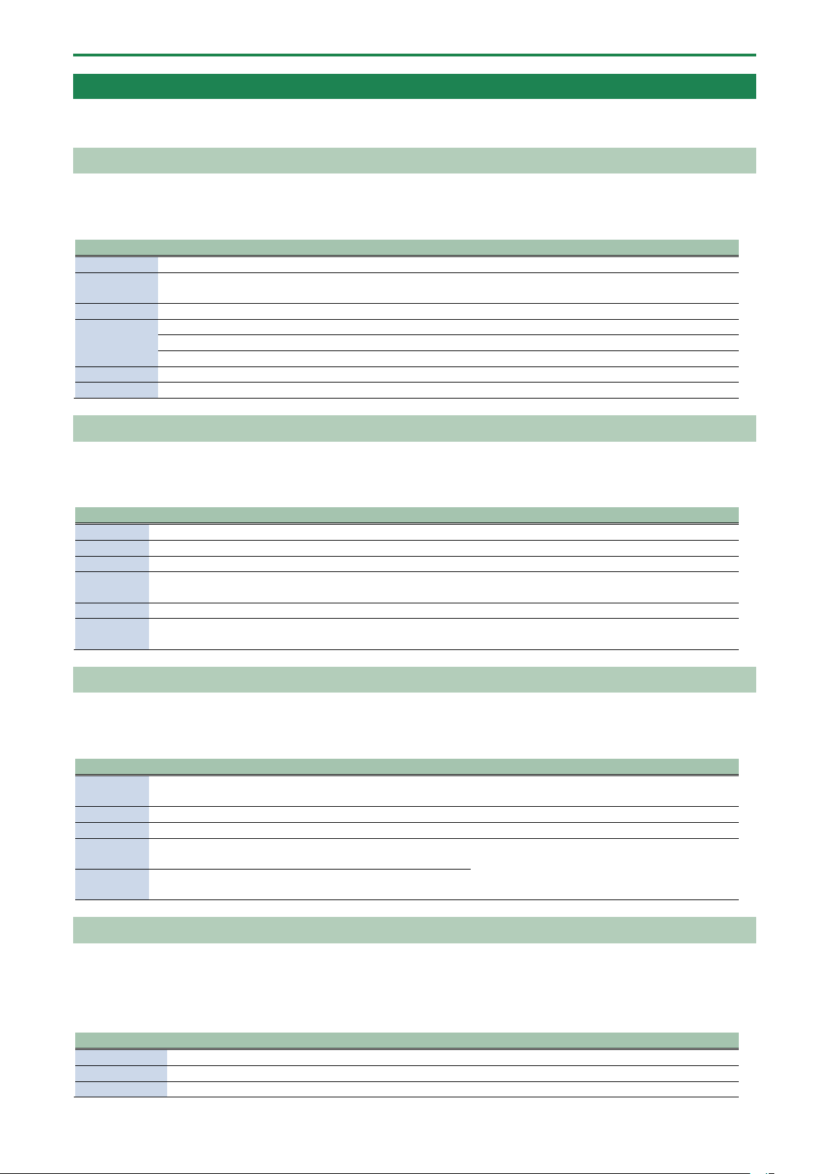
Appendix
129
MFX List
Filter+Drive
This is a filter with overdrive.
It cuts the specified frequencies and adds distortion.
Parameter
Value
Explanation
CUTOFF
20–16000 (Hz)
Sets the cutoff frequency range in which the filter works.
RESONANCE
0–100
Adjusts the filter’s resonance level.
The larger the value, the more that the frequency range set in CUTOFF is emphasized.
DRIVE
0–100
Adds distortion.
FLT TYPE
Sets the type of filter.
HPF
Cuts off the low frequencies.
LPF
Cuts off the high frequencies.
LOW FREQ
20–16000 (Hz)
Adjusts the frequency range that’s boosted or cut by the LOW GAIN parameter.
LOW GAIN
-24–24 (dB)
Adjusts the amount of boost/cut applied to the frequency range that’s set in LOW FREQ.
Resonator
This effect uses “Karplus-Strong synthesis”, which is often used in physical modeling of sounds.
This lets you alter the sound with a maximum of six “resonators” that match different keys or chords.
Parameter
Value
Explanation
ROOT
C1–G9
Sets the reference pitch (root note).
BRIGHT
0–100
Adjusts the tonal brightness.
FEEDBACK
0–99 (%)
Adjusts the amount of feedback for the effect.
CHORD
Root, Oct, UpDn, P5, m3, m5, m7, m7oct, m0, m11,
M3, M5, M7, M7oct, M9, M11
Sets the composite notes (chord) to resonate.
PANNING
0–100
Sets the panning for the resonator.
ENV MOD
0–100
Larger values increase the amount of feedback
according to the input level.
Sync Delay
Gives an echo effect in sync with the tempo.
Parameter
Value
Explanation
TIME
1/32, 1/16T, 1/32D, 1/16, 1/8T, 1/16D, 1/8, 1/4T, 1/8D, 1/4,
1/2T, 1/4D, 1/2, 1/1T, 1/2D, 1/1
Sets the sound delay time.
FEEDBACK
0–99 (%)
Adjusts the amount of feedback for the effect.
LEVEL
0–100
Adjusts the volume of the effect sound.
L DAMP F
FLAT, 80, 100, 125, 160, 200, 250, 315, 400, 500, 630, 800
(Hz)
Sets the frequency range that is attenuated each
time the delay repeats.
H DAMP F
630, 800, 1000, 1250, 1600, 2000, 2500, 3150, 4000, 5000,
6300, 8000, 10000, 12500, FLAT (Hz)
Isolator
This effect lets you cut off sounds in a specified frequency range.
Parameter
Value
Explanation
LOW
-INF, -41.87–+12 (dB)
Adjusts the amount of boost/cut in the low-frequency range.
MID
-INF, -41.87–+12 (dB)
Adjusts the amount of boost/cut in the mid-frequency range.
HIGH
-INF, -41.87–+12 (dB)
Adjusts the amount of boost/cut in the high-frequency range.
Appendix
130
DJFX Looper
This effect loops the sound in short cycles.
You can vary the playback direction and playback speed of the input sound to get a turntable-type effect.
Parameter
Value
Explanation
LENGTH
0.230–0.012
(sec)
Sets the length of the loop.
SPEED
-100–100
Sets the playback direction and playback speed.
The loop plays backward when this is set to a negative value, stops when this is set to zero,
and plays forward when this is set to a positive value.
LOOP SW
OFF, ON
Turn this ON while a sound is playing to make the sound play back in a loop, at a length
specified by the LENGTH parameter.
Turn this OFF to disable the loop.
Scatter
This effect swaps the sound played back by a loop in steps, altering its playback direction and gate length. This gives you the loop
playback a digital groove feeling.
Parameter
Value
Explanation
TYPE
1–10
Sets the scatter type.
DEPTH
10, 20, 30, 40, 50, 60, 70, 80, 90, 100
Adjusts the scatter depth.
SCATTER
OFF, ON
Switches the scatter effect on/off.
SPEED
SINGLE, DOUBLE
Sets the scatter speed.
Downer
Cyclically slows down the audio playback speed.
Parameter
Value
Explanation
DEPTH
0–100
Sets how much the playback speed should be slowed down.
RATE
1/32, 1/16, 1/8, 1/4,
1/2, 1, 2
Sets the period at which the playback speed is changed.
FILTER
0–100
Attenuates the high-frequency range.
PITCH
OFF, ON
When this is turned ON, pitches that were lowered due to the change in speed are
converted to their original pitch.
RESONANCE
0–100
Adjusts the filter’s resonance level.
Increasing the value further emphasizes the effect, for a more unusual sound.
Ha-Dou
This effect generates a wave-like sound based on the input audio.
Parameter
Value
Explanation
MOD
DEPTH
0–100
Adjusts the depth of the effect sound.
TIME
0–100
Sets the length of the effect sound.
LEVEL
0–100
Adjusts the volume of the effect sound.
LOW CUT
FLAT, 20, 25, 31, 40, 50, 63, 80, 100, 125, 160, 200, 250, 315,
400, 500, 630, 800 (Hz)
Sets the frequency range at which the effect
sound is attenuated.
HIGH CUT
630, 800, 1000, 1250, 1600, 2000, 2500, 3150, 4000, 5000,
6300, 8000, 10000, 12500, FLAT (Hz)
PRE DELAY
0–100
Sets the time it takes for the effect to sound.
Appendix
131
Ko-Da-Ma
This creates a reverberating audio effect.
Parameter
Value
Explanation
TIME
1/32, 1/16T, 1/32D, 1/16, 1/8T, 1/16D,
1/8, 1/4T, 1/8D, 1/4, 1/2T, 1/4D, 1/2, 1/1T,
1/2D, 1/1
Sets how much the effect sound is delayed.
FEEDBACK
0–99 (%)
Adjusts how much the effect sound is repeated.
SEND
0–100
Adjusts the volume of sound sent to the effect.
L DAMP F
FLAT, 80, 100, 125, 160, 200, 250, 315,
400, 500, 630, 800 (Hz)
Sets the frequency range that is attenuated each time the delay
repeats.
H DAMP F
630, 800, 1000, 1250, 1600, 2000, 2500,
3150, 4000, 5000, 6300, 8000, 10000,
12500, FLAT (Hz)
MODE
SINGLE, PAN
When this is set to “SINGLE”, the effect sound comes from the
center; and when this is set to “PAN”, the effect sound is heard on
the left and the right.
Zan-Zou
For left and right sounds, this effect applies delay to the negative phase of the sound. This gives the lingering effect of a sonic
“afterimage”.
The effect works for stereo sound, and does not have any effect on mono sound.
Parameter
Value
Explanation
TIME
1–100 (when the SYNC parameter is OFF)
1/32, 1/16T, 1/32D, 1/16, 1/8T, 1/16D, 1/8, 1/4T, 1/8D,
1/4, 1/2T, 1/4D, 1/2, 1/1T, 1/2D, 1/1 (when the SYNC
parameter is ON)
Sets the sound delay time.
FEEDBACK
0–99
Adjusts the amount of feedback for the effect.
HF DAMP
200, 250, 315, 400, 500, 630, 800, 1000, 1250, 1600,
2000, 2500, 3150, 4000, 5000, 6300, 8000, OFF (Hz)
Sets the frequency range at which the effect sound
is attenuated (how clearly defined the afterimage
sounds).
LEVEL
0–100
Adjusts the volume of the effect sound.
MODE
2TAP, 3TAP, 4TAP
Sets how the effect sound lingers.
SYNC
OFF, ON
When this is ON, the effect sound synchronizes with
the tempo.
To-Gu-Ro
This gives the sound an undulating effect, based on the image of a coiled-up snake.
Parameter
Value
Explanation
DEPTH
0–100
Adjusts how much the playback speed should be
slowed down.
RATE
0–100 (when the SYNC parameter is OFF)
1/128, 1/64, 1/32, 1/16, 1/8, 1/4, 1/2, 1/1, 2/1 (when
the SYNC parameter is ON)
Sets the period at which the playback speed is
lowered.
RESONANCE
0–100
Adjusts the filter’s resonance level.
Increasing the value further emphasizes the effect,
for a more unusual sound.
FLT MOD
0–100
Attenuates the high-frequency range according to
the playback speed.
AMP MOD
0–100
Attenuates the volume according to the playback
speed.
SYNC
OFF, ON
When this is ON, the effect sound synchronizes with
the tempo.
Appendix
132
SBF
A sideband filter that lets specific frequency components pass through.
Parameter
Value
Explanation
INTERVAL
0–100
Sets the band interval. Larger values produce wider band intervals, and the frequency
of each band increases.
WIDTH
0–100
Sets the bandwidth. Larger values produce a narrower bandwidth, which further
isolates the specific frequency components that pass through the filter.
BALANCE
100-0–0-100 (%)
Adjusts the volume balance between dry (the original sound) and effect sound.
TYPE
SBF1, SBF2, SBF3,
SBF4, SBF5, SBF6
Sets the range in which the filter works.
GAIN
-INF, -52.3–+10.0
(dB)
Adjusts the volume of the effect sound.
Stopper
This effect lowers the sample playback speed, reproducing the sound of a turntable stopping.
Parameter
Value
Explanation
DEPTH
0–100
Adjusts how much the playback speed should be slowed down.
RATE
1/128, 1/64, 1/32, 1/16, 1/8, 1/4, 1/2,
1, 2
Sets the period at which the playback speed is changed.
RESONANCE
0–100
Adjusts the filter’s resonance level.
Increasing the value further emphasizes the effect, for a more
unusual sound.
FLT MOD
0–100
Attenuates the high-frequency range according to the playback
speed.
AMP MOD
0–100
Lowers the volume according to the playback speed.
Tape Echo
This is a virtual tape echo effect that gives a realistic tape delay sound.
The effect simulates the tape echo section of a Roland RE-201 Space Echo.
Parameter
Value
Explanation
TIME
10–800 (ms)
Sets the tape speed.
Larger values make the tape speed slower, which creates a longer interval between
delay sounds.
FEEDBACK
0–99
Adjusts the volume of the delay repeat sound.
LEVEL
0–100
Adjusts the volume of the effect sound.
MODE
S, M, L, S+M, S+L, M+L,
S+M+L
Selects the combination of playback heads to use.
W/F RATE
0–100
Sets the speed of wow/flutter (the complex variation in pitch caused by tape wear
and rotational irregularity).
W/F
DEPTH
0–100
Sets the depth of wow/flutter.
TimeCtrlDly
This is a delay in which the delay time can be varied smoothly.
Parameter
Value
Explanation
TIME
0–100
Sets the sound delay time.
FEEDBACK
0–99
Adjusts the amount of feedback for the effect.
LEVEL
0–100
Sets the volume of the effect sound.
L DAMP F
FLAT, 80, 100, 125, 160, 200, 250, 315, 400, 500, 630, 800
(Hz)
Sets the frequency range that is attenuated each
time the delay repeats.
H DAMP F
630, 800, 1000, 1250, 1600, 2000, 2500, 3150, 4000, 5000,
6300, 8000, 10000, 12500, FLAT (Hz)
Appendix
133
Parameter
Value
Explanation
SYNC
OFF, ON
When this is ON, the effect sound synchronizes
with the tempo.
Super Filter
This is a filter with an extremely sharp slope (attenuation characteristics). The cutoff frequency can be varied cyclically.
Parameter
Value
Explanation
CUTOFF
0–100
Sets the frequency range in which the filter works (the cutoff frequency). Higher values increase
the frequency range.
RESONANCE
0–100
Adjusts the filter’s resonance level.
The larger the value, the more that the frequency range set in CUTOFF is emphasized.
FLT TYPE
Sets the filter type.
LPF
A low-pass filter. This filter lets frequencies pass through that are higher than the frequency range
set in CUTOFF.
BPF
A band-pass filter. This filter lets frequencies pass through that are near the frequency range set in
CUTOFF.
HPF
A high-pass filter. This filter lets frequencies pass through that are higher than the frequency range
set in CUTOFF.
DEPTH
0–100
Sets the depth of the effect.
RATE
0–100
Sets the cycle (period) of the effect.
SYNC
OFF,
ON
When this is ON, the effect sound synchronizes with the tempo.
WrmSaturator
This is a saturator effect with a characteristic warm sound.
This effect may output a very loud sound, depending on how the parameters are set. Use caution not to raise the values too
much.
Parameter
Value
Explanation
DRIVE
0–48 (dB)
Adjusts the strength of the distortion.
Eq LOW
-24–24 (dB)
Adjusts the amount of boost/cut for the low-frequency range.
Eq HIGH
-24–24 (dB)
Adjusts the amount of boost/cut for the high-frequency range.
LEVEL
0–100
Adjusts the volume of the effect sound.
303 VinylSim
This effect models the Vinyl Sim effect of the SP-303. The effect simulates the sound of an analog record playing.
Parameter
Value
Explanation
COMP
0–100
Sets the compression feel, a unique part of the analog record’s sound.
NOISE
0–100
Adjusts the volume of the noise.
WOW FLUT
0–100
Sets the inconsistencies (wow/flutter) heard when the analog record “rotates”.
LEVEL
0–100
Adjusts the volume of the effect sound.
404 VinylSim
This effect models the Vinyl Sim effect of the SP-404SX. The effect simulates the sound of an analog record playing.
Parameter
Value
Explanation
FREQUENCY
0–100
Sets the frequency characteristics of the playback system.
NOISE
0–100
Adjusts the volume of the noise.
WOW FLUT
0–100
Sets the inconsistencies (wow/flutter) heard when the analog record “rotates”.
Appendix
134
Cassette Sim
This effect simulates the sound of a cassette tape playing.
Parameter
Value
Explanation
TONE
0–100
Sets the tone.
HISS
0–100
Adjusts the volume of the noise.
AGE
0–60 (years)
Sets how many years the cassette tape has deteriorated.
DRIVE
0–100
Adjusts the amount of distortion.
WOW FLUT
0–100
Sets the inconsistencies (wow/flutter) heard when the cassette tape plays back.
CATCH
0–100
Sets how much the cassette tape has stretched out.
Lo-fi
Degrades the tonal character.
Parameter
Value
Explanation
PRE FILT
1–6
Sets the type of pre-filter (the filter that the sound passes
through before effects are applied).
LOFI TYPE
1–9
Larger settings cause more tonal degradation.
TONE
-100–100
Sets the tone. Larger settings emphasize the high-frequency
range. Smaller settings emphasize the low-frequency range.
CUTOFF
200, 250, 315, 400, 500, 630, 800, 1000, 1250,
1600, 2000, 2500, 3150, 4000, 5000, 6300,
8000 (Hz)
Sets the frequency range in which the post-filter (the filter
that the sound passes through after effects are applied)
works.
BALANCE
100-0–0-100
Adjusts the volume balance between dry (the original sound)
and effect sound.
LEVEL
0–100
Adjusts the volume of the effect sound.
This effect may output a very loud sound, depending on how the parameters are set. Use caution not to raise the values too
much.
Reverb
Adds reverberation to the sound.
Parameter
Value
Explanation
TYPE
AMBI, ROOM, HALL1, HALL2
Sets the type of reverb.
TIME
0–100
Sets the reverb time.
LEVEL
0–100
Adjusts the volume of the effect sound.
LOW CUT
FLAT, 20–800 (Hz)
Sets the frequency range at which the effect sound is attenuated.
HIGH CUT
630–12500, FLAT (Hz)
PRE DELAY
0–100 (ms)
Sets the time before the effect sound is output.
Chorus
Adds spaciousness and richness to the sound.
Parameter
Value
Explanation
DEPTH
0–100
Sets the depth of the effect sound.
RATE
0.33–2.30 (sec)
Sets the cycle (period) of the effect sound.
BALANCE
100-0–0-100 (%)
Adjusts the volume balance between dry (the original sound) and effect sound.
EQ LOW
-15–15 (dB)
Adjusts the amount of boost/cut of the low-frequency range.
EQ HIGH
-15–15 (dB)
Adjusts the amount of boost/cut of the high-frequency range.
LEVEL
0–100
Adjusts the volume of the effect sound.
JUNO Chorus
This effect models the chorus section of the Roland JUNO-106 and JX series.

Appendix
135
Parameter
Value
Explanation
MODE
JUNO 1, JUNO 2, JUNO12, JX-1 1,
JX-1 2
Sets the type of effect.
NOISE
0–100
Adjusts the volume of noise generated by the effect.
BALANCE
100-0–0-100 (%)
Adjusts the volume balance between dry (the original sound) and effect
sound.
Flanger
This effect creates modulation like a jet airplane taking off and landing.
Parameter
Value
Explanation
DEPTH
0–100
Sets the depth of the effect sound.
RATE
0–100 (when the SYNC parameter is OFF)
4.000–0.016 (bars; when the SYNC
parameter is ON)
Sets the cycle (period) of the effect sound.
MANUAL
0–100
Sets the frequency range in which the effect is applied.
Smaller values reduce the flanging effect in the low end.
RESONANCE
0–100
Adjusts the filter’s resonance level.
Increasing the value further emphasizes the effect, for a more
unusual sound.
BALANCE
100-0–0-100 (%)
Adjusts the volume balance between dry (the original sound)
and effect sound.
SYNC
OFF, ON
When this is ON, the effect sound synchronizes with the tempo.
Phaser
This effect creates modulation by adding a phase-shifted sound.
Parameter
Value
Explanation
DEPTH
0–100
Sets the depth of the effect sound.
RATE
0–100 (when the SYNC parameter is OFF)
4.000–0.016 (bars; when the SYNC
parameter is ON)
Sets the cycle (period) of the effect sound.
MANUAL
0–100
Sets the frequency range in which the effect is applied.
Larger values reduce the phasing effect in the low end.
RESONANCE
0–100
Adjusts the filter’s resonance level.
Increasing the value further emphasizes the effect, for a more
unusual sound.
BALANCE
100-0–0-100 (%)
Adjusts the volume balance between dry (the original sound)
and effect sound.
SYNC
OFF, ON
When this is ON, the effect sound synchronizes with the tempo.
Wah
This effect gives a wah-wah sound, by cyclically changing the tone.
Parameter
Value
Explanation
PEAK
0–100
Larger values narrow the frequency range at which the effect
is applied.
RATE
0–100 (when the SYNC parameter is OFF)
1.000–0.010 (bars; when the SYNC parameter
is ON)
Sets the cycle (period) of the effect.
MANUAL
0–100
Sets the frequency range in which the effect is applied.
DEPTH
0–100
Sets the depth of the effect.
FLT TYPE
Sets the filter type.
LPF
Applies the effect over a wide frequency range.
BPF
Applies the effect over a narrow frequency range.
SYNC
OFF, ON
When this is ON, the effect sound synchronizes with the
tempo.
Appendix
136
Slicer
This slices the sound up into small pieces, creating the impression that a backing phrase is being played.
This slices up the sound at certain intervals into 16 parts (16 steps), breaking the sound into a rhythm that follows the sequence
pattern (a pattern used for slicing up the sound). This is effective when used with sustaining sounds.
Parameter
Value
Explanation
PATTERN
1–32
Sets the sequence pattern.
SPEED
0–100 (when the SYNC parameter is
OFF)
2/1 to 1/64T (bars; when the SYNC
parameter is ON)
Sets the period over which the sequence pattern repeats.
DEPTH
0–100
Sets the slicing depth. Larger settings make the slicing effect more
prominent.
SHUFFLE
0–100
Larger settings delay the timing of even-numbered steps (2, 4...).
MODE
Sets how the volume changes when the next step sounds.
LEGATO
The volume is not changed between steps.
SLASH
The volume is reset to zero before the next step sounds (at the
boundary between steps).
SYNC
OFF, ON
When this is ON, the effect sound synchronizes with the tempo.
Tremolo/Pan
Cyclically varies the volume or panning.
Parameter
Value
Explanation
DEPTH
0–100
Sets the depth of the effect.
RATE
0–100 (when the SYNC parameter is OFF)
1.000–0.010 (when the SYNC parameter is
ON)
Sets the cycle (period) of the effect.
TYPE
Sets the type of effect.
TRE
Cyclically changes the volume (tremolo).
PAN
Cyclically changes the panning.
WAVE
Sets how the effect modulates the sound.
TRI
Triangle wave
SQR
Square wave
SIN
Sine wave
SAW1, SAW2
Sawtooth wave
TRP
Trapezoidal wave
SYNC
OFF, ON
When this is ON, the effect sound synchronizes with the
tempo.
Chromatic PS
A two-voice pitch shifter that changes the pitch in semitone steps.
Parameter
Value
Explanation
PITCH1, PITCH2
-24–12 (semi)
Adjusts the amount that PITCH1 or PITCH2 is pitch-shifted.
BALANCE
100-0–0-100 (%)
Adjusts the volume balance between dry (the original sound) and effect sound.
PAN1, PAN2
L50–R50
Sets the panning of PITCH1 or PITCH2.
Hyper-Reso
This is a resonator effect that is adjusted to make creating melodies and bass lines easier.
Parameter
Value
Explanation
NOTE
-17– -1, 1–18
Sets which note in the chromatic scale should resonate, counting from the
root of the SCALE value.
Appendix
137
Parameter
Value
Explanation
SPREAD
UNISON, TINY, SMALL,
MEDIUM, HUGE
Sets the octave of the resonator.
CHARACTER
0–100
Adjusts the brightness and detuning of the sound.
SCALE
C maj–B maj, C min–B min
Sets the composite notes (chord) to resonate.
FEEDBACK
0–99 (%)
Adjusts the amount of feedback for the effect.
ENV MOD
0–100
Larger values increase the amount of feedback according to the input level.
Ring Mod
This effect alters the tonal character to make the sound more metallic.
Parameter
Value
Explanation
FREQUENCY
0–100
Sets the frequency range to which the effect is applied.
SENS
0–100
Adjusts the volume of the effect sound.
BALANCE
100-0–0-100 (%)
Adjusts the volume balance between dry (the original sound) and effect sound.
POLARITY
OFF, ON
Sets the direction in which the frequency modulation moves.
EQ LOW
-15–15 (dB)
Adjusts the amount of boost/cut of the low-frequency range.
EQ HIGH
-15–15 (dB)
Adjusts the amount of boost/cut of the high-frequency range.
Crusher
Produces a lo-fi effect.
Parameter
Value
Explanation
FILTER
331–15392
(Hz)
Sets the frequency range in which the pre-filter (the filter that the sound passes through
before effects are applied) works.
RATE
0–100
Sets the sample rate of the effect. Larger values make the sample rate lower, for a more lo-fi
sound.
BALANCE
100-0–0-100
(%)
Adjusts the volume balance between dry (the original sound) and effect sound.
Overdrive
Mildly distorts the sound.
Parameter
Value
Explanation
DRIVE
0–100
Adjusts the amount of distortion.
TONE
-100–100
Sets the tone. Larger settings emphasize the high-frequency range. Smaller settings
emphasize the low-frequency range.
BALANCE
100-0–0-100
(%)
Adjusts the volume balance between dry (the original sound) and effect sound.
LEVEL
0–100
Adjusts the volume of the effect sound.
Distortion
Intensely distorts the sound.
Parameter
Value
Explanation
DRIVE
0–100
Adjusts the amount of distortion.
TONE
-100–100
Sets the tone. Larger settings emphasize the high-frequency range. Smaller settings
emphasize the low-frequency range.
BALANCE
100-0–0-100
(%)
Adjusts the volume balance between dry (the original sound) and effect sound.
LEVEL
0–100
Adjusts the volume of the effect sound.
Appendix
138
Equalizer
This is a three-band equalizer.
Parameter
Value
Explanation
LOW GAIN
-15–15 (dB)
Adjusts the amount of boost/cut of the low-
frequency range.
MID GAIN
-15–15 (dB)
Adjusts the amount of boost/cut of the
mid-frequency range.
HIGH GAIN
-15–15 (dB)
Adjusts the amount of boost/cut of the
high-frequency range.
LOW FREQ
20, 25, 31, 40, 50, 63, 80, 100, 125, 160, 200, 250, 315, 400 (Hz)
Sets the low-frequency range.
Mid Freq
200, 250, 315, 400, 500, 630, 800, 1000, 1250, 1600, 2000, 2500,
3150, 4000, 5000, 6300, 8000 (Hz)
Sets the mid-frequency range.
HIGH FREQ
2000, 2500, 3150, 4000, 5000, 6300, 8000, 10000, 12500, 16000
(Hz)
Sets the high-frequency range.
Compressor
This effect reduces high volume levels while bringing up the level of quieter sounds, smoothing out any variations in overall
volume.
Parameter
Value
Explanation
SUSTAIN
0–100
Sets how long the effect is applied to the decaying sound.
ATTACK
0–100
Sets how long it takes to reduce the volume when a high input level is detected.
RATIO
0–100
Sets the compression ratio.
LEVEL
0–100
Adjusts the volume of the effect sound.
This effect may output a very loud sound, depending on how the parameters are set. Use caution not to raise the values too
much.
SX Reverb
This adds reverberation to the sound.
As with the SP-404SX, you can adjust the volume balance between the dry (original) sound and the effect sound with this effect.
Parameter
Value
Explanation
TIME
0–100
Sets the reverb time.
TONE
-12–+12
Adjusts the tonal character of the reverb.
BALANCE
100-0–0-100 (%)
Adjusts the volume balance between the dry (original) sound and effect sound.
SX Delay
Gives an echo effect in sync with the tempo.
As with the SP-404SX, you can adjust the volume balance between the dry (original) sound and the effect sound with this effect.
Parameter
Value
Explanation
TIME
1/32, 1/16T, 1/32D, 1/16, 1/8T, 1/16D, 1/8, 1/4T, 1/8D,
1/4, 1/2T, 1/4D, 1/2, 1/1T, 1/2D, 1/1
Sets the sound delay time.
FEEDBACK
0–99 (%)
Adjusts the amount of feedback for the effect.
BALANCE
100-0–0-100 (%)
Adjusts the volume balance between the dry
(original) sound and effect sound.
Cloud Delay
Adds multiple delays to the dry sound, as well as reverberations for a thick “cloudy” effect.
Parameter
Value
Explanation
WINDOW
0–100
Adjusts the interval for the delayed sound.
Larger settings produce a deeper reverberation.
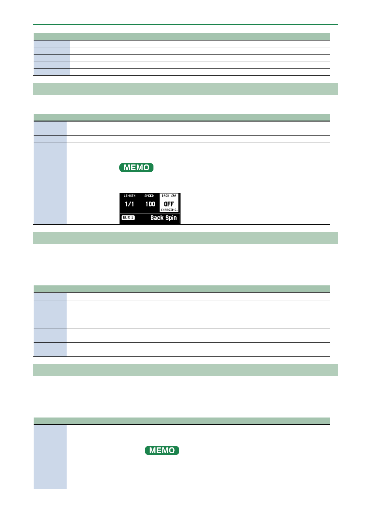
Appendix
139
Parameter
Value
Explanation
PITCH
-12–+12
Adjusts the volume of the pitch shifter for the effect sound.
BALANCE
100-0–0-100 (%)
Adjusts the volume balance between the dry (original) sound and effect sound.
FEEDBACK
0–99 (%)
Adjusts the amount of feedback for the effect.
CLOUDY
0–100
Adjusts the thickness of the effect sound.
LO-FI
OFF, ON
When this is ON, the tonal character of the effect sound is degraded.
Back Spin
This gives the effect of spinning a record backwards.
Parameter
Value
Explanation
LENGTH
1/1, 1/2, 1/4, 1/8,
1/16
Sets the length of the back spin.
SPEED
0–100
Sets the speed of the back spin.
BACK SW
OFF, ON
If you turn this ON while a sound is playing, the back spin plays for a length of time
specified by the LENGTH parameter.
Turn this OFF to disable the back spin.
After switching to this effect, the sample must be played back (charged) for up to
approximately three seconds.
The BACK SW parameter blinks during charging.
Auto Pitch
Processes the human voice to create a variety of characters.
* This is enabled with INPUT FX.
Parameter
Value
Explanation
PITCH
-100–100
Sets the pitch of the voice. You can change the pitch up and down one octave.
FORMANT
-100–100
Sets the formant of the voice. Lower settings give a more masculine vocal
character, and higher settings give a more feminine vocal character.
BALANCE
100-0–0-100 (%)
Adjusts the volume balance between dry (the original sound) and effect sound.
AT PITCH
0–100
Adjusts the strength at which the pitch is corrected.
KEY
CHROMA, A, B³, B, C, D³, D,
E³, E, F, G³, G, A³
Adjusts the key to which the pitch is corrected.
ROBOT
OFF, ON
When this is turned ON, the inputted voice is altered to a voice without
inflection, staying at the same pitch.
Vocoder
Changes the voice to a vocoder voice.
* This is enabled with INPUT FX.
Parameter
Value
Explanation
NOTE
-17– -1, 1–18
Sets which note in the chromatic scale should sound, counting from the root of
the SCALE value. The scale and chord structure that is used depends on the
SCALE and CHORD settings.
The NOTE value can be controlled via note messages from a MIDI keyboard
connected to the MIDI IN connector, a computer connected via USB, a DAW
app running on an iOS device and so on.
At that time, you can send pitch bend messages to continuously change the
pitch.
Appendix
140
Parameter
Value
Explanation
For note messages (Note Number = 0–127) and pitch bend messages, set the
MIDI channel on your external device to “11”.
FORMANT
-100–100
Adjusts the formant of the voice. Lower settings give a more masculine vocal
character, and higher settings give a more feminine vocal character.
TONE
-100–100
Adjusts the brightness of the effect sound.
SCALE
C maj–B maj, C min–B min
Sets the scale to use and its root.
CHORD
Root, P5, Oct, UpDn,
UpDnP5, 3rd, 5thUp,
5thDn, 7thUp, 7thDn
Sets the chord structure.
BALANCE
100-0–0-100
Adjusts the volume balance between dry (the original sound) and effect sound.
Harmony
This effect adds a harmony to your voice.
Parameter
Value
Explanation
PITCH
-100–100
Sets the pitch of the voice. You can change the pitch up and down
one octave.
FORMANT
-100–100
Sets the formant of the voice.
Lower settings give a more masculine vocal character, and higher
settings give a more feminine vocal character.
BALANCE
100-0–0-100 (%)
Adjusts the volume balance between the dry (original) sound and
effect sound.
AT PITCH
0–100
Adjusts the strength at which the pitch is corrected.
KEY
CHROMA, A, B³, B, C, D³, D, E³, E, F, G³,
G, A³
Sets the key to which the pitch is adjusted and the harmonies are
added.
HARMONY
Root, P5, Oct, UpDn, UpDnP5, 3rd,
5thUp, 5thDn, 7thUp, 7thDn
Sets the harmonization.
Gt Amp Sim
This effect models a guitar amplifier.
* This is enabled with INPUT FX.
Parameter
Value
Explanation
AMP TYPE
Selects the guitar amp type.
JC
Models the sound of a Roland JC-120.
TWIN
Models a Fender Twin Reverb.
BG
Models a lead guitar sound played using a MESA/Boogie combo amp.
MATCH
Models a Matchless D/C-30.
MS
Models a Marshall 1959.
SLDN
Models a Soldano SLO-100.
DRIVE
0–100
Adjusts the volume and distortion of the amp.
LEVEL
0–100
Adjusts the volume of the effect sound.
BASS
-100–100
Adjusts the low-frequency tonal character.
MIDDLE
-100–100
Adjusts the midrange tonal character.
TREBLE
-100–100
Adjusts the high-frequency tonal character.
Control change messages and corresponding effects
You can use a control change message (CC#83) to select the effects.
The effects (selectable effects) corresponding to the respective CC#83 values are shown below.
BUS1 (MIDI ch 1), BUS2 (MIDI ch 2)
Value of CC#83
Effect name
0
(OFF)
1
Direct FX1

Appendix
141
Value of CC#83
Effect name
2
Direct FX2
3
Direct FX3
4
Direct FX4
5
Direct FX5
6
Scatter
7
Downer
8
Ha-Dou
9
Ko-Da-Ma
10
Zan-Zou
11
To-Gu-Ro
12
SBF
13
Stopper
14
Tape Echo
15
TimeCtrlDly
16
Super Filter
17
WrmSaturator
18
303 VinylSim
19
404 VinylSim
20
Cassette Sim
21
Lo-fi
22
Reverb
23
Chorus
24
JUNO Chorus
25
Flanger
26
Phaser
27
Wah
28
Slicer
29
Tremolo/Pan
30
Chromatic PS
31
Hyper-Reso
32
Ring Mod
33
Crusher
34
Overdrive
35
Distortion
36
Equalizer
37
Compressor
38
SX Reverb
39
SX Delay
40
Cloud Delay
41
Back Spin
42–127
–
BUS3 (MIDI ch 3), BUS4 (MIDI ch 4)
Value of CC#83
Effect name
0
(OFF)
1
303 VinylSim
2
404 VinylSim
3
Cassette Sim
4
Lo-fi
5
Downer
6
Compressor
7
Equalizer
8
Isolator
9
Super Filter
10
Filter+Drive
11
WrmSaturator
12
Overdrive
13
Distortion
14
Crusher
15
Ring Mod
16
SBF
Appendix
142
Value of CC#83
Effect name
17
Resonator
18
Hyper-Reso
19
Chromatic PS
20
Reverb
21
Ha-Dou
22
Zan-Zou
23
Sync Delay
24
TimeCtrlDly
25
Ko-Da-Ma
26
Tape Echo
27
Chorus
28
JUNO Chorus
29
Flanger
30
Phaser
31
Wah
32
Slicer
33
Tremolo/Pan
34
To-Gu-Ro
35
DJFX Looper
36
Scatter
37
SX Reverb
38
SX Delay
39
Cloud Delay
40–127
–
INPUT FX (MIDI ch 5)
Value of CC#83
Effect name
0
(OFF)
1
Auto Pitch
2
Vocoder
3
Harmony
4
Gt Amp Sim
5
Chorus
6
JUNO Chorus
7
Reverb
8
TimeCtrlDly
9
Chromatic PS
10
Downer
11
WrmSaturator
12
303 VinylSim
13
404 VinylSim
14
Cassette Sim
15
Lo-fi
16
Equalizer
17
Compressor
18–127
–
Appendix
143
List of Shortcut Keys
You can quickly recall a desired function or screen by pressing a button or pad while holding down the [SHIFT] button.
● Shortcuts that use the [SHIFT] button(P.143)
● Shortcuts that use the [REMAIN] button(P.144)
● Shortcuts that use the [VALUE] button(P.144)
● Shortcuts that use the [DEL] button(P.145)
● Shortcuts that use the [COPY] button(P.145)
● Shortcuts that use the [MFX] button(P.145)
● Shortcuts used in DJ mode(P.145)
● Shortcuts used in TR-REC(P.146)
Shortcuts that use the [SHIFT] button
While holding down the
[SHIFT] button
Function Explanation
Pad [1]
FIXED VELOCITY
Sets the sample’s velocity so that it always plays back at 127 (the maximum).
Pad [2]
16 VELOCITY
Changes a sample’s velocity (volume) in steps when it plays back.
Pad [3]
CUE
Adjusts the balance of the audio you monitor via the PHONES jack.
Pad [4]
CHROMATIC
Lets you play back samples (changing their pitches) as a chromatic scale with
the pads.
Pad [5]
EXCHANGE
Exchanges (swaps) the sample or pattern data saved in different pads.
Pad [6]
INIT PARAM
Initializes the sample parameters for the selected pad.
Pad [7]
PAD LINK
Lets you play back all the pads at the same time that are assigned to a group, by
using a single pad.
Pad [8]
MUTE GROUP
Groups together samples that you don’t want to play together (samples that
you don’t want layered).
Pad [9]
METRONOME
Turns the metronome on/off.
Pad [10]
COUNT-IN
Adds a count-in before sampling or pattern recording begins.
Pad [11]
TAP TEMPO
Lets you set the tempo in an intuitive way by tapping the pad in time, as if you
were clapping out the beat.
Pad [12]
GAIN
Displays the UTILITY MENU > SYSTEM > GAIN tab.
Pad [13]
UTILITY
Displays the UTILITY MENU screen.
Pad [14]
IMPORT/EXPORT
Displays the UTILITY MENU > IMPORT (IMPORT/EXPORT MENU).
Pads [15]
PAD SETTING
Displays the UTILITY MENU > PAD SET (PAD SETTING).
Pad [16]
EFX SETTING
Displays the UTILITY MENU > EFX SET (EFX SETTING) screen.
[BUS FX] button
MUTE BUS
Temporarily turns off the audio sent to the bus (the sample playback sound or
the sound inputted to the INPUT jack), and outputs only the sound of the effect.
[HOLD] button
PAUSE
Pauses the sample that’s currently playing back.
[EXT SOURCE] button
INPUT SETTING
Displays the input settings screen.
[SUB PAD] button
PROJECT
Displays the SELECT PROJECT screen.
[MARK] button (at least
three seconds)
SAVE EFX
PARAMETER
Saves the main parameters of the effects assigned to BUS 1 and BUS 2.
[PITCH/SPEED] button
ENVELOPE
Sets how the volume changes when the sample plays back.
[START/END] button
CHOP
Splits the sample at the marker positions, and assigns the resulting samples to
separate pads.
[PATTERN SELECT] button
UNDO
Undoes the data you just inputted (recorded).
* Enabled only when recording a pattern
[ROLL] button
ROLL SET
This shows how to set the roll interval (how fast the roll repeats).
[REVERSE] button + pads
[1]–[16]
PAD MUTE
Switches the pad mute on/off.
[REVERSE] button +
[REMAIN] button
PAD MUTE MODE
Keeps the [SHIFT] and [REVERSE] buttons in “pressed-down” state.
[LOOP] button
PING-PONG LOOP
Loops the sample by repeatedly playing back forward and then backward.
[GATE] button
GATE ALL ON/OFF
Turns the GATE parameter for all samples in the selected bank on/off.
[BPM SYNC] button
SYNC ALL ON/OFF
Turns the BPM SYNC parameter for all samples in the selected bank on/off.
Appendix
144
While holding down the
[SHIFT] button
Function Explanation
[REC] button
TR-REC
Switches to pattern recording using TR-REC.
This lets you record a sample onto the pattern that’s playing back.
* Enabled only when playing back a pattern
Bank [A/F]–[E/J] buttons
BANK VOLUME
Adjusts the volume for the specified bank overall.
[REMAIN] button (at least
three seconds)
LIVE MODE
Use this to disable buttons that are not used when playing live (sampling and
edit-related buttons).
[COPY] button
BANK PROTECT
This function prevents the samples and patterns assigned to a pad from being
copied, overwritten by editing or accidentally deleted.
[EXIT] button
STOP
Stops the playback of all samples.
Shortcuts that use the [REMAIN] button
While holding down the [REMAIN] button
Function (explanation)
Pads [1]–[16]
Sets which sample playback audio is sent to which bus (meaning which
effects are used) for each sample.
Bank [A/F]–[E/J] buttons
Sets the bus send destination for all samples in a bank.
[MFX] button
Makes the effect edit screen keep displaying.
[BUS FX] button
You can swap the effects of BUS 1 and BUS 2.
Edits the following parameters on the
pitch/speed settings screen
● SPEED
● PITCH
● VOLUME
● PAN
● BPM
● BPM SYNC
● GATE
● LOOP
● REVERSE
Lets you simultaneously edit the parameters of samples that are registered to
the same bank.
Edits the following parameters on the envelope
settings screen
● ATTACK
● HOLD
● RELEASE
● BPM SYNC
● GATE
● LOOP
● REVERSE
Lets you simultaneously edit the parameters of samples that are registered to
the same bank.
Shortcuts that use the [VALUE] button
While holding down the [VALUE] knob
Function (explanation)
Pads [1]–[16]
Selects a sample (no sound is produced).
Also, selects a pattern when [PATTERN SELECT] is lit (the pattern does not play back).
[BUS FX] button
Temporarily bypasses BUS 3 and BUS 4.
[SUB PAD] button
This minimizes the slight differences in timing when you play multiple samples at the
same time.
Effect buttons ([FILTER+DRIVE]–[MFX]
button)
Applies effects only while you hold down the effect buttons (EFFECT GRAB).
[GATE] button
Switches the “one-shot playback” sample playback mode on/off.
Appendix
145
Shortcuts that use the [DEL] button
While holding down the [DEL] button
Function (explanation)
[MARK] button
Deletes the effect operations recorded using EFX MOTION REC from a pattern.
* Enabled on the pattern edit screen
[REVERSE] button
Deletes the pad mute operations recorded using EFX MOTION REC from a pattern.
* Enabled on the pattern edit screen
[EXIT] button
Deletes all samples or patterns in a bank.
Shortcuts that use the [COPY] button
While holding down the [COPY] button
Function (explanation)
Edits the following parameters on the pitch/speed
settings screen
● SPEED
● PITCH
● VOLUME
● PAN
● BPM
● BPM SYNC
● GATE
● LOOP
● REVERSE
Lets you simultaneously edit the parameters of samples that are registered
to the same mute group.
Edits the following parameters on the envelope
settings screen
● ATTACK
● HOLD
● RELEASE
● BPM SYNC
● GATE
● LOOP
● REVERSE
Lets you simultaneously edit the parameters of samples that are registered
to the same mute group.
[EXIT] button
Copies all samples or patterns in a bank to a different bank.
Shortcuts that use the [MFX] button
While holding down the [MFX] button
Function (explanation)
[DJFX LOOPER] button
Displays the MFX LIST from #17 onwards.
[ISOLATOR] button
Displays the MFX LIST from #33 onwards.
Shortcuts used in DJ mode
Operation
Parameter
Explanation
[SHIFT] button + [REVERSE]
button + pad [13] (CH1)
[SHIFT] button + [REVERSE]
button + pad [15] (CH2)
MUTE
Mutes the sample that’s playing back.
[SHIFT] button + pads [1]–
[16]
–
You can play back a sample from the position of the marker that’s set for that
sample.

Appendix
146
Operation
Parameter
Explanation
[SHIFT] button + [REMAIN]
button
–
The [SHIFT] button remains in a “pressed-down” state. This makes it easier to select
a marker and play back.
Press the [EXIT] button to cancel this behavior.
[SHIFT] button + [MARK]
button
–
You can add markers while playing samples in DJ mode.
[SHIFT] button +
[START/END] button
–
You can edit markers while playing samples in DJ mode.
[SHIFT] button + [DEL]
button + pads [1]–[16]
–
While in DJ mode, you can delete the markers you’ve set for samples.
[SHIFT] button + [ROLL]
button
ROLL SIZE
Sets the roll interval (1/4, 1/2, 1 or 2 measures).
Set the ROLL SIZE before playing back rolls. (You can’t change the ROLL SIZE with
this operation while a roll is playing back).
[ROLL] button + pad [13]
(CH1)
[ROLL] button + pad [15]
(CH2)
–
Repeats the sample playback in more detailed intervals (ROLL).
Note that when the ROLL SIZE (roll interval) is longer than the sample length, a roll
cannot played back.
[ROLL] button + pads [1]–[4]
–
Changes the roll interval while the roll is playing back.
[ROLL] button + pad [1]: quarter-note (1/4 of a measure)
[ROLL] button + pad [2]: half-note (1/2 of a measure)
[ROLL] button + pad [3]: whole note (1 measure)
[ROLL] button + pad [4]: two whole notes (2 measures)
[REMAIN] + pad [14] (CH1)
[REMAIN] + pad [16] (CH2)
BUS FX
You can set the bus to which the CH1/CH2 sample playback is sent (meaning
which effects are used).
While holding down the [REMAIN] button, each time you press pad [14] or pad [16]
switches the effect to use as follows: “BUS-1” -> “BUS-2” -> “DRY” -> “BUS-1”.
Press [RESAMPLE] button +
[VALUE] knob
VOLUME
CURVE
Selects the volume curve characteristics used for each slider (CH1 LEVEL, CH2
LEVEL, X-FADE) in DJ mode.
Each time you hold down the [RESAMPLE] button and press the [VALUE] knob, the
characteristic switches in this order: “FAST CUT” -> “LINEAR” -> “SQUARE” ->
“CUBIC” -> “FAST CUT”.
[DEL] button + pad [2] + pad
[6] (CH1)
[DEL] button + pad [4] + pad
[8] (CH2)
BPM
Resets the tempo to the default value.
[START/END] button
–
Switches between the functions (CUE MIX or X-FADE) for the [CTRL 3] knob.
[PITCH/SPEED] button
–
Changes the number of digits shown for the BPM.
Each time you press the [PITCH/SPEED] button, the display switches in the
following order: integers only -> to the second decimal place -> to the first decimal
place -> integers only....
When you set the BPM value using pads [2] [4] (BPM+) and pads [6] [8] (BPM-), the
number of digits shown for the BPM changes according to the minimum unit.
[MARK] button
–
Switches between the EFX and MIXER screen views.
[BPM SYNC] button
–
Selects the channel (CH1/CH2) used to control reverse playback ([REVERSE]
button).
Shortcuts used in TR-REC
Operation
Explanation
[DEL] button + [A/F] button
Deletes the notes (for one measure) corresponding to the selected
pad.
[DEL] button + [B/G] button
Deletes the notes (for one measure) corresponding to all pads.
[ROLL] button + [CTRL 1] knob
You can record the motion of [CTRL 1] knob in the steps.
* This is enabled when MODE is “TRIG”.
[ROLL] button + [CTRL 2] knob
You can record the motion of [CTRL 2] knob in the steps.
* This is enabled when MODE is “TRIG”.
[ROLL] button + [CTRL 3] knob
You can record the motion of [CTRL 3] knob in the steps.
* This is enabled when MODE is “TRIG”.
[VALUE] knob (press) + [SUB PAD] button + pads [1]–
[16]
You can select samples without playing them back.

Appendix
147
Error Messages
Error messages
Explanation
Action
Battery Low!
The batteries are nearly depleted.
Replace the batteries, or switch to an AC adaptor.
→
“About the Power Supply(P.8)”
Unsupported
FILE
The file type is not supported on this unit.
Check the file extension, format and folder directory.
→
“Importing/Exporting (Using the SD Card)(P.114)”
No SD CARD!
No SD card is inserted. Also, the SD card
might not be fully inserted.
Turn off the power, and make sure that the SD card is fully
inserted before you turn the power back on.
Unsupported
SD Card!
An unsupported type of SD card has been
inserted.
Please format the SD card.
→
“Formatting an SD Card(P.121)”
SD CARD
Protected!
The write-protect feature has been enabled
on the SD card.
Unlock the lock switch on the left side of the SD card.
SD CARD Full!
The SD card has run out of free space.
Delete any unneeded data on the card.
Internal Storage
Full!
There is not enough storage capacity left
on this unit.
Delete any unneeded data on the unit.
Storage Error!
A problem has occurred with the internal
storage.
Try performing a factory reset.
→
“Restoring the Factory Settings (FACTORY RESET)(P.122)”
Protected!
The function can’t be executed because
bank protect is enabled.
Use a bank for which bank protect is disabled, or disable bank
protect on the currently selected bank.
→ “Selecting a Sample Bank(P.12)” “Selecting a Pattern
Bank(P.67)” “Protecting a Sample (PROTECT)(P.57)” “Protecting a
Pattern (PROTECT)(P.80)”
Max Length
Pattern
The maximum number of notes that can be
recorded to the pattern sequencer has
been exceeded.
Reduce the number of notes in the pattern, or shorten and split
the pattern to record.
→ “Creating a New Pattern (Real-time Recording)(P.60)”
“Creating a New Pattern (TR-REC)(P.62)”
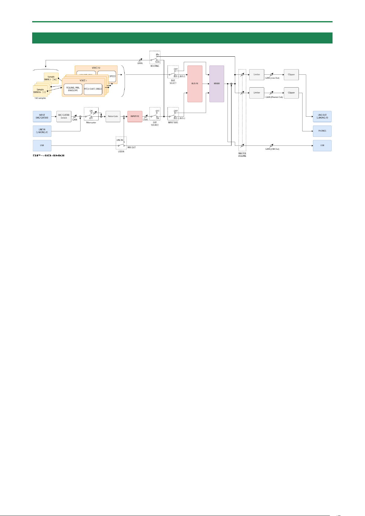
Appendix
148
Audio Diagram

Appendix
149
Main Specifications
Maximum polyphony
32 voices
Recordable Data
Samples: 2,560 (16 samples x 10 banks x 16 projects: stored in internal storage)
Patterns: 2,560 (16 patterns x 10 banks x 16 projects: stored in internal storage)
Internal storage
Size: 16 GB
*Include preload data
Maximum sampling time
16 minutes (approximately 185 MB per sample)
Skip back sampling time
Maximum 25 seconds (Always records LINE OUT signal independently of
sampling/resample)
Data format
16-bit linear
Import format
WAV, AIFF, MP3 import supported.
*SP-404MK2 App supports WAV, AIFF, MP3, FLAC, M4A.
Sample rate
48 kHz
Pattern sequencer
Resolution: 480 ticks per quarter note
Pattern length: 1 to 64 bars
Recording method: Realtime Loop Recording (with shuffle quantize function), TR-REC
(Automation supported)
Effects
Multi-effects: 41 types
Input effects: 17 types
Pads
16 pads + 1 sub pad (Velocity-sensitive pad)
Controllers
Control knob x 3
Display
Graphic OLED display
External storage
SD card (SDHC compatible, commercially available)
* For backup, restore, import, and export functions
Connection terminals
PHONES jacks: 1/4-inch phone type, Stereo miniature phone type
LINE OUT (L/MONO, R) jacks: 1/4-inch TRS phone type (impedance balanced)
LINE IN (L/MONO, R) jacks: 1/4-inch phone type
MIC/GUITAR IN jacks: 1/4-inch TRS phone type (for MIC), 1/4-inch phone type (for
GUITAR)
MIDI (IN, OUT) jack: Stereo miniature phone type
USB terminal: USB Type-C
®
(Audio, MIDI)
DC IN jack
Power supply
AC adaptor
USB bus power supply (USB Type-C
®
port, 1.5 A or more)
Ni-MH batteries (AA, HR6) (commercially available) x 6 or Alkaline battery (AA, LR6)
(commercially available) x 6
Current draw
1,100 mA (AC adaptor)
1,500 mA (USB bus power)
Expected battery life under
continuous use
Alkaline battery: Approx. 2.5 hours
Ni-MH battery: Approx. 3.5 hours
* This can vary depending on the specifications of the batteries, capacity of the
batteries, and the conditions of use.
External dimensions
178 (W) x 276 (D) x 71 (H) mm
7 (W) x 10-7/8 (D) x 2-13/16 (H) inches
Weight (excluding AC adaptor)
1.1 kg
2 lbs 7 oz
Accessories
Quick Start
“Read Me First” leaflet
AC adaptor
Warranty card
Options (sold separately)
TRS/MIDI connecting cable: BOSS BMIDI series, BOSS BCC series
Wireless MIDI Expression Pedal: BOSS EV-1-WL
* This document explains the specifications of the product at the time that the document was issued. For the latest
information, refer to the Roland website.
Appendix
150
MIDI Implementation Chart
Model: SP-404MK2
Date: Mar. 9, 2023
Version: 3.00
Function
Transmitted
Recognized
Remarks
Basic
Channel
Default
× (MIDI mode A)
1–10 (MIDI mode B)
× (MIDI mode A)
1–10 (MIDI mode B)
*1
Changed
× (MIDI mode A)
1–10 (MIDI mode B)
× (MIDI mode A)
1–10 (MIDI mode B)
*1
Mode
Default
×
Mode 3
Messages
×
×
Altered
-
×
Note
Number
35–51 (B1–E³3, MIDI
mode A) *1
0, 12–91 (C-1, C0–G6,
MIDI mode B) *1
36–60 (C2–C4, CH 16) *7
35–51 (B1–E³3, MIDI
mode A) *1
0, 12–91 (C-1, C0–G6,
MIDI mode B) *1
0–127 (CH 11) *2
36–60 (C2–C4, CH 16) *6
True Voice
-
36–51 (C2–E³3, MIDI
mode A) *1
12–91 (C0–G6, MIDI
mode B) *1
Velocity
Note On
○
○
Note Off
×
×
Aftertouch
Key’s
×
×
Channel’s
×
×
Pitch Bend
×
○
*2
Control
Change
CC#16–19
×
○
*7
Example:
0xB0 10 00 -> BUS 1 Ctrl 1=0
0xB1 13 7F -> BUS 2 EFX switch
= ON
CC#80–83
×
○ *7
Example:
0xB2 50 7F -> BUS 3 Ctrl 4=127
0xB3 53 01 -> BUS 4 EFX number
= 01 (303 VinylSim)
CC#07
○
*8
○
*8
Example:
0xB1 07 7F -> CH2 volume slider
= 127
CC#08
○
*8
○
*8
Example:
0xB0 08 7F -> X-FADE = 0:127
(CH1 = 0, CH2 = 127)
CC#20–27
○
*8
×
Example:
0xB0 14 01 -> CH1 play
0xB2 1A 7F -> press the pattern
sequencer [BPM+] button
Program Change
×
○
*1 *9
Example:
0xC3 0F -> Bank D Pattern 16
System Exclusive
×
×
System
Common
Song Position
×
×
Song Select
×
×
Tune Request
×
×
System
Realtime
Clock
○
*3
○
*4
Commands
○
*3
○
*4
Aux
Messages
All Sound Off
×
○
*5
Reset All
Controllers
×
×
Local On/Off
×
×
All Notes Off
×
×
Active Sensing
○
○
System Reset
×
×
Notes
*1: Refer to “MIDI Note Map(P.152)”.
*2: Enabled when INPUT FX is “Vocoder” (MIDI CH 11).
Appendix
151
Function
Transmitted
Recognized
Remarks
*3: Output when MIDI Sync Out is “ON” and when there is no tempo input from an external device.
*4: Enabled when this unit is in remote mode (when a tempo signal is received from an external device).
*5: All samples stop playing back when the MIDI cable is unplugged.
*6: Enabled when playing samples in chromatic mode (MIDI CH 16).
*7:
MIDI channels
CH 1: BUS 1
CH 2: BUS 2
CH 3: BUS 3
CH 4: BUS 4
CH 5: INPUT
Control change message numbers and corresponding EFX controls
CC#19
EFX switch (0–63: OFF, 64–127: ON)
CC#83
EFX number (0–127)
“Control change messages and corresponding effects(P.140)”
CC#16
Ctrl 1 (0–127)
CC#17
Ctrl 2 (0–127)
CC#18
Ctrl 3 (0–127)
CC#80
Ctrl 4 (0–127)
CC#81
Ctrl 5 (0–127)
CC#82
Ctrl 6 (0–127)
*8:
Control change message numbers and corresponding controllers in DJ mode
MIDI channel 1 (CH1 sample)
MIDI channel 2 (CH2 sample)
MIDI channels 3 (pattern
sequencer)
CC#7
[Ctrl 1] knob: CH1 volume
slider (0–127)
[Ctrl 2] knob: CH2 volume
slider (0–127)
[Ctrl 1] knob: pattern sequencer
volume slider (0–127)
CC#8
[Ctrl 3] knob: X-FADE (CH1:
CH2 = 127:0–0:127)
-
-
CC#20
[ñ] button (0: pause, 127:
play)
[ñ] button (0: pause, 127:
play)
[ñ] button (0: pause, 127:
play)
CC#21
[õ] button (0: release the
button, 127: press the button)
[õ] button (0: release the
button, 127: press the button)
[õ] button (0: release the
button, 127: press the button)
CC#22
[SYNC] button (0: Off, 127: On)
[SYNC] button (0: Off, 127: On)
[SYNC] button (0: Off, 127: On)
CC#23
[CUE] button (0: Off, 127: On)
[CUE] button (0: Off, 127: On)
[CUE] button (0: Off, 127: On)
CC#24
[BEND+] button (0: release the
button, 127: press the button)
[BEND+] button (0: release the
button, 127: press the button)
[BEND+] button (0: release the
button, 127: press the button)
CC#25
[BEND-] button (0: release the
button, 127: press the button)
[BEND-] button (0: release the
button, 127: press the button)
[BEND-] button (0: release the
button, 127: press the button)
CC#26
[BPM+] button (0: release the
button, 127: press the button)
[BPM+] button (0: release the
button, 127: press the button)
[BPM+] button (0: release the
button, 127: press the button)
CC#27
[BPM-] button (0: release the
button, 127: press the button)
[BPM-] button (0: release the
button, 127: press the button)
[BPM-] button (0: release the
button, 127: press the button)
*9:
Program change numbers and corresponding patterns
PC#0
Pattern 1
PC#1
Pattern 2
:
:
PC#15
Pattern 16
Mode 1: OMNI ON, POLY
Mode 2: OMNI ON, MONO
Mode 3: OMNI OFF, POLY
Mode 4: OMNI OFF, MONO
○: Yes
×: No
Appendix
152
MIDI Note Map
MIDI Mode
A
B
MIDI Channel
CH 1
…
CH 10
CH 1–9
CH 2–10
Note Number
BANK
PAD
…
BANK
PAD
BANK
PAD
BANK
PAD
127
G9
Blank
…
Blank
Blank
(for Note Offset)
Blank
(for Note Offset)
:
:
92
A³6
91
G6
E
4
J
4
90
F´6
3
3
89
F6
2
2
88
E6
1
1
87
E³6
8
8
86
D6
7
7
85
C´6
6
6
84
C6
5
5
83
B5
12
12
82
B³5
11
11
81
A5
10
10
80
A³5
9
9
79
G5
16
16
78
F´5
15
15
77
F5
14
14
76
E5
13
13
75
E³5
D
4
I
4
74
D5
3
3
73
C´5
2
2
72
C5
1
1
71
B4
8
8
70
B³4
7
7
69
A4
6
6
68
A³4
5
5
67
G4
12
12
66
F´4
11
11
65
F4
10
10
64
E4
9
9
63
E³4
16
16
62
D4
15
15
61
C´4
14
14
60
C4
13
13
59
B3
C
4
H
4
58
B³3
3
3
57
A3
2
2
56
A³3
1
1
55
G3
8
8
54
F´3
7
7
53
F3
6
6
52
E3
5
5
51
E³3
A
4
…
J
4
12
12
50
D3
3
3
11
11
49
C´3
2
2
10
10
48
C3
1
1
9
9
47
B2
8
8
16
16
46
B³2
7
7
15
15
45
A2
6
6
14
14
44
A³2
5
5
13
13
43
G2
12
12
B
4
G
4
42
F´2
11
11
3
3
41
F2
10
10
2
2
40
E2
9
9
1
1
39
E³2
16
16
8
8
38
D2
15
15
7
7
Appendix
153
MIDI Mode
A
B
37
C´2
14
14
6
6
36
C2
13
13
5
5
35
B1
EXT SOURCE
12
12
34
B³1
Blank
…
Blank
11
11
33
A1
10
10
32
A³1
9
9
31
G1
16
16
30
F´1
15
15
29
F1
14
14
28
E1
13
13
27
E³1
A
4
F
4
26
D1
3
3
25
C´1
2
2
24
C1
1
1
23
B0
8
8
22
B³0
7
7
21
A0
6
6
20
A³0
5
5
19
G0
12
12
18
F´0
11
11
17
F0
10
10
16
E0
9
9
15
E³0
16
16
14
D0
15
15
13
C´0
14
14
12
C0
13
13
11
B-1
Blank
(for Note Offset)
Blank
(for Note Offset)
:
:
1
C´-1
0
C-1
EXT SOURCE

Appendix
154
SP-404MK2 (Version 3.00)
Reference Manual
02
Roland Corporation
©2021 Roland Corporation