Loading ...
Loading ...
Loading ...
2-2A
8
Installation
2-2A
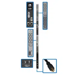
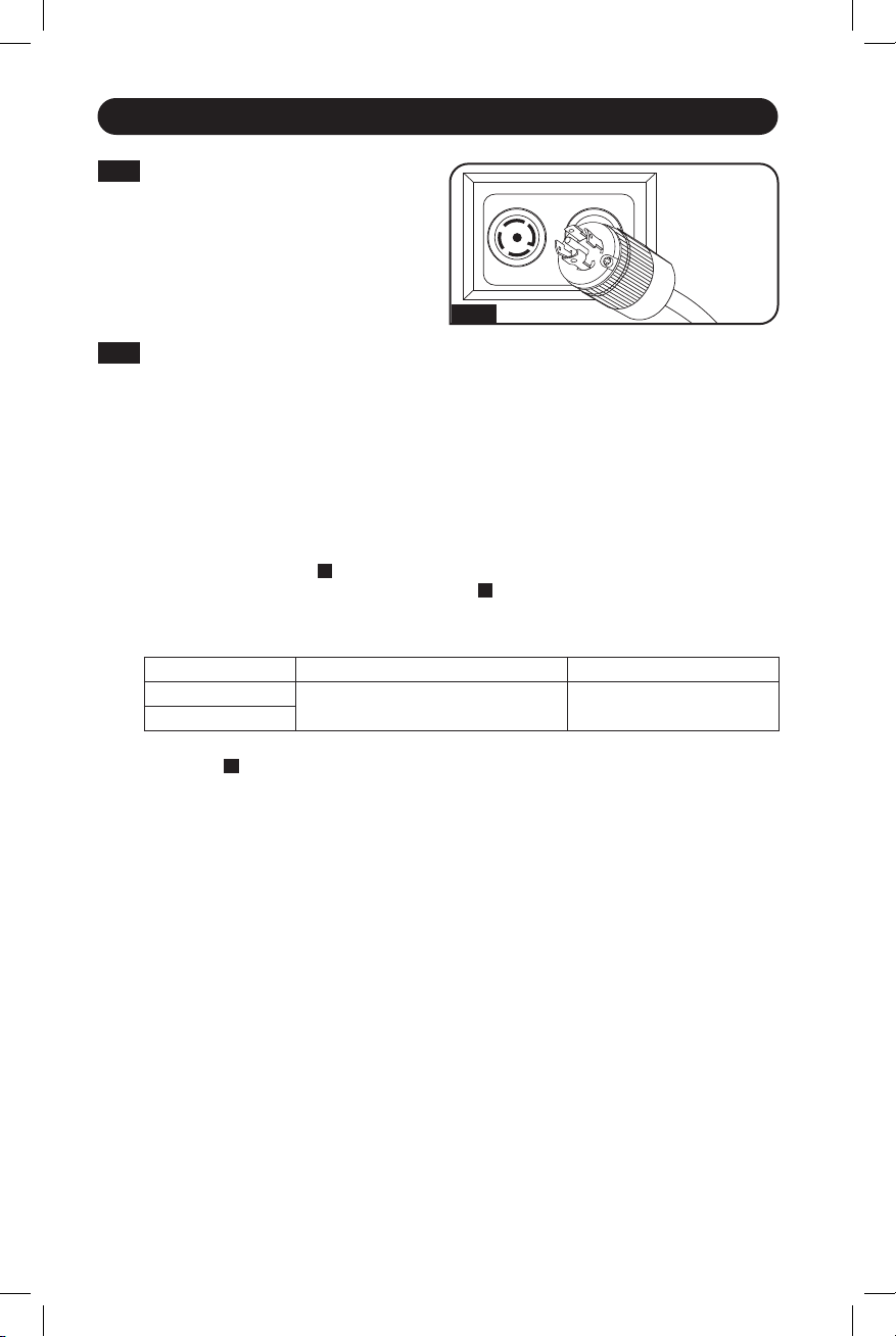
Corded Models - Connect the input
plug to your facility’s compatible AC
power source and input connection.
Plug type may
vary by model.
2-2B
Hardwire Models (PDU3XEVSRHWA and PDU3XEVSRHWB only)
WARNING
Only qualified personnel should perform hardwire installations. Wire codes and
requirements differ from area to area. Permanent connection to the branch circuit
shall be done by an approved wiring method in accordance with the local electrical
requirements. Use of copper wiring with ferrules is recommended for AC input
terminal connections. Each input terminal connection should be torqued to the
listed specification. Improperly sized wiring, inadequate torque, or use of non-
copper wiring can result in overheating of input terminal connections.
These models do not come equipped with an input cable. Conduit and adapters are
installed to the endplate
A
, wires are channeled through the conduit and adapters to the
terminal block, located behind the access plate
B
.
Note: An appropriate disconnect device rated for the application shall be provided as part of the
building installation.
Model Recommended Wire Gauge / Type Torque Specifications
PDU3XEVSRHWA
#6 AWG Copper Wire (13.3 mm
2
) 12.2 in•lbf (1.38 N•m)
PDU3XEVSRHWB
To access the terminal block, remove the access plate screws located on the rear panel
of the PDU
C
. Then remove the access plate to make the input wire connections. Use an
appropriate length of 3/4” EMT conduit for connection from the location of the disconnect
device to the PDU. Connect the conduit using 3/4” adapters to the cutout on the endplate
of the PDU.
Use an appropriate length of 8 THHN wire from the disconnect device to the PDU for each
terminal connection and ground.
21-02-090 93-349E-EN.indd 821-02-090 93-349E-EN.indd 8 2/18/2021 8:53:05 AM2/18/2021 8:53:05 AM
Loading ...
Loading ...
Loading ...