Loading ...
Loading ...
Loading ...
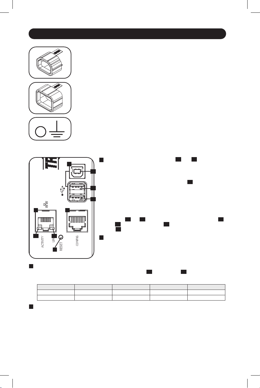
ACTIVITY
LINK
RESET
CONFIG
A
BC
D
A1
C1 C2
A2
A3
16
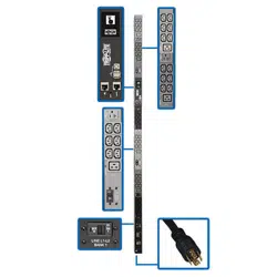
Features
A
USB Ports: The two USB-A ports
A1
and
A2
connect
to one of four different Tripp Lite EnviroSense2 (E2)
environmental sensors* for remote temperature or
temperature/humidity monitoring (up to three E2 sensors
can be daisy-chained). The USB-B port
A3
is used for
initial network interface configuration and direct console
access from a laptop**.
*USB-A ports are designed for use with E2 modules only. Do not
connect other USB devices to these ports.
**Only 2 of 3 USB ports can be used simultaneously. For example:
2 USB-A (
A1
and
A2
), or 1 USB-B and the lower USB-A port (
A3
and
A1
); the upper USB-A port
A2
cannot connect with the USB-B
port
A3
.
B
RJ45 Configuration Port: This port can also be used to
configure the network interface and command line access
from a laptop.
D
SNMP Reset Button: The reset button is recessed. Use a paper clip or other suitable object
to press the reset button for 3 seconds to reboot the PDU’s network interface. Rebooting
the network interface will not erase network settings or interrupt AC power. Press and hold
the reset button for 20 seconds to restore the PDU’s network interface to its factory default
settings. Restoring to the factory default will erase all previously saved data—including
network settings—without interrupting AC power.
Ground Screw: Use this to connect any equipment that requires a
chassis ground.
C20 Plug-Lock Inserts (Optional): Use the included C20 plug-lock
inserts to secure plugs to C19 receptacles. Attach the sleeve to the plug
making sure the pull tabs remain outside the plug and that the fit is
secure. To unplug equipment properly, use the pull tabs to remove the
plug and insert from the receptacle.
C14 Plug-Lock Inserts (Optional): Use the included C14 plug-lock
inserts to secure plugs to C13 receptacles. Attach the sleeve to the plug
making sure the pull tabs remain outside the plug and that the fit is
secure. To unplug equipment properly, use the pull tabs to remove the
plug and insert from the receptacle.
C
Ethernet Port: Use this RJ45 jack to connect the PDU to the network with a standard
Ethernet patch cable. The behavior of the Activity LED
C1
and Link LED
C2
is shown in the
table below. This port is not compatible with PoE (Power Over Ethernet) applications.
LED Function LED Color Off On Flashing
Activity Green No Activity — Activity
Link Yellow No Link
Link (Any Speed)
—
Network Interface
21-02-090 93-349E-EN.indd 1621-02-090 93-349E-EN.indd 16 2/18/2021 8:53:08 AM2/18/2021 8:53:08 AM
Loading ...
Loading ...