Loading ...
Loading ...
Loading ...
2-3
2-4
B
A
10
Installation
Networking the PDU
Your PDU can receive IP address assignments via DHCP server (dynamic) or static (manual)
addressing methods. See the LX Platform User’s Guide for an explanation of these methods. You
can find the guide by going to tripplite.com/support and typing LX Platform in the search field. If
you are uncertain which method to use, contact your network administrator for assistance before
continuing the configuration process.
Note: The MAC address of the PDU (12-digit string in this format: 000667xxxxxx) is printed on a label attached
to the PDU enclosure.
2-3
Connect your equipment’s input plugs to
the appropriate outlets on the PDU. The
LED near each outlet illuminates when
the outlet is ready to distribute live
AC power.
Note: It is recommended that you do not
connect a live load to the PDU. If the load you
intend to connect has an ON/OFF switch, please
turn the switch to OFF prior to connection.
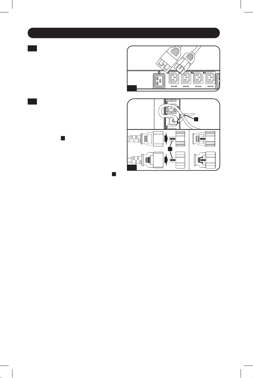
2-4
Optional Cord Retention Procedure
Option 1: Use the bridge lances located
near each receptacle to retain power
cords. Tie each equipment power cord
to a bridge lance by looping the cord
and securing it with one of the included
cable ties
A
.
Make sure each cord can
be unplugged from the PDU without
removing the cable tie.
Option 2: Use the included C14 and
C20 plastic sleeves to secure plugs to
receptacles. Attach the sleeve to the
plug, making sure that the pull tabs
B
remain outside the plug and that the fit
is secure. To unplug equipment properly,
use the pull tabs to remove the plug
and sleeve from the receptacle.
21-02-090 93-349E-EN.indd 1021-02-090 93-349E-EN.indd 10 2/18/2021 8:53:06 AM2/18/2021 8:53:06 AM
Loading ...
Loading ...
Loading ...