Loading ...
Loading ...
Loading ...
Electrical I 0
IZ_WARNINGI Hazardous voltage. Can shock, burn, or
kill. Connect ground wire before connecting power sup-
ply wires. Use the wire size (including the ground wire)
specified in the wiring chart. If possible, connect the
pump to a separate branch circuit with no other appli-
ances on it.
I_kWARNINGIExplosion hazard. Do not ground to a gas
supply line.
WIRING CONNECTIONS
I_i'WARNINGI Fire hazard. Incorrect voltage can cause a
fire or seriously damage the motor and voids the warran-
ty. The supply voltage must be within _+10%of the motor
nameplate voltage.
NOTICE: Dual-voltage motors are factory wired for 230
volts. If necessary, reconnect the motor for 1] 5 volts, as
shown. Do not alter the wiring in single voltage motors.
Install, ground, wire, and maintain your pump in compli-
ance with the National Electrical Code (NEC) or the
Canadian Electrical Code (CEC), as applicable, and with
all local codes and ordinances that apply. Consult your
local building inspector for code information.
Connection Procedure:
Step 1. Connect the ground wire first as shown in Figure
14. The ground wire must be a solid copper wire
at least as large as the power supply wires.
Step 2. There must be a solid metal connection between
the pressure switch and the motor for motor
grounding protection. If the pressure switch is not
connected to the motor, connect the green
ground screw in the switch to the green ground
screw under the motor end cover. Use a solid
copper wire at least as large as the power supply
wires.
Step 3. Connect the ground wire to a grounded lead in a
service panel, to a metal underground water
pipe, to a metal well casing at least ten feet (3M)
long, or to a ground electrode provided by the
power company or the hydro authority.
Step 4. Connect the power supply wires to the pressure
switch as shown in Figure 14.
You have just completed the wiring for your pump.
Please go to Page 11 or 12 for startup preparations.
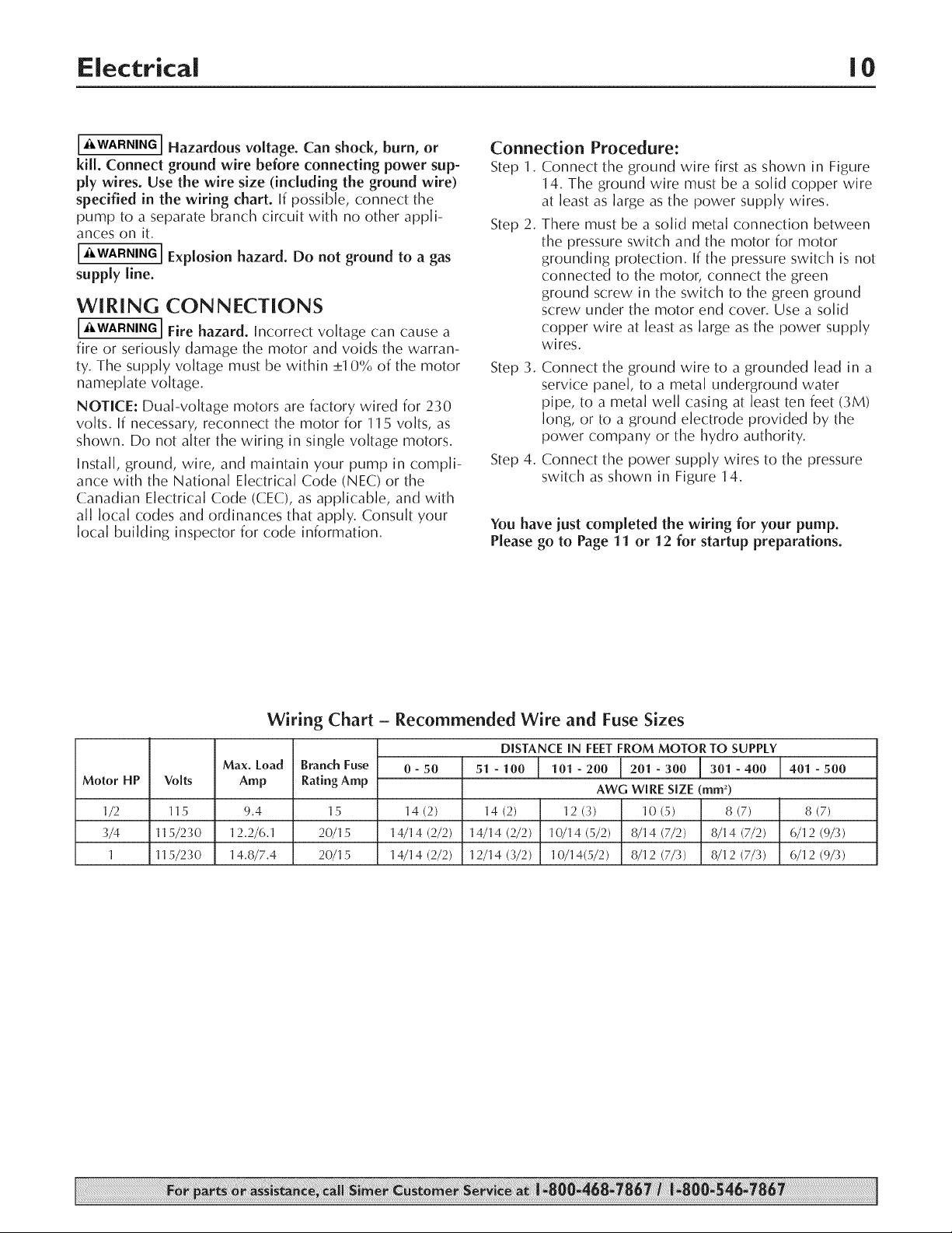
Motor HP Volts
1/2 115
3/4 115/230
1 115/230
Wiring Chart - Recommended Wire and Fuse Sizes
Max. Load
Amp
Branch Fuse
Rating Amp
DISTANCE [N FEET FROM MOTOR TO SUPPLY
0 - 50 51 - 100 101 - 200 201 - 300 301 - 400 401 - 500
9.4 15 14 (2) 14 (2) 8 (7)
12.2/6.1 20/15 14/14 (2/2) 14/14 (2/2) 6/12 (9/3)
14.8/7.4 20/15 14/14 (2/2) 12/14 (3/2) 6/12 (9/3)
AWG WIRE SIZE (ram 2)
12 (3) 10 (5) 8 (7)
10/14(5/2) 8/14 (7/2) 8/14 (7/2)
10/14(5/2) 8/12 (7/3) 8/12 (7/3)
Loading ...
Loading ...
Loading ...