INSTRUCTION MANUAL
MANUAL DE INSTRUCCIONES
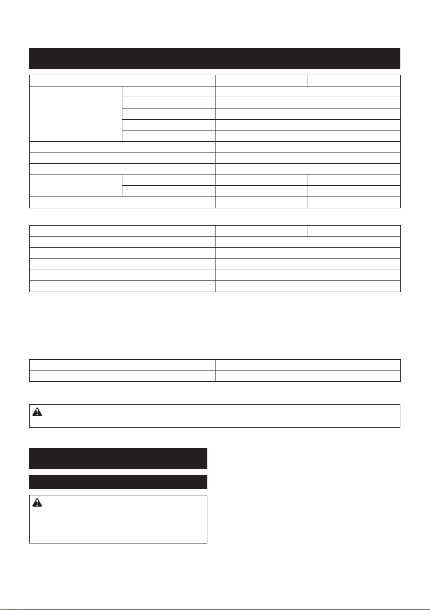
Cordless Combination Hammer
Martillo Rotativo Combinado
Inalámbrico
GRH01
GRH02
IMPORTANT: Read Before Using.
IMPORTANTE: Lea antes de usar.
2 ENGLISH
ENGLISH (Original instructions)
SPECIFICATIONS
Model: GRH01 GRH02
Capacities Concrete 28 mm (1-1/8")
Core bit 54 mm (2-1/8")
Diamond core bit (dry type) 65 mm (2-9/16")
Steel 13 mm (1/2")
Wood 32 mm (1-1/4")
No load speed 0 - 980/min
Blows per minute 0 - 5,000/min
Rated voltage D.C. 36 V - 40 V max
Overall length with BL4025 358 mm (14-1/8″) 389 mm (15-1/4″)
with BL4040 373 mm (14-3/4″) 404 mm (15-7/8″)
Net weight 3.9 - 4.6 kg (8.6 - 10.1 lbs) 4.1 - 4.6 kg (9.0 - 10.1 lbs)
Optional accessory
Model: DX12 (For GRH01) DX14 (For GRH02)
Suction performance 350 l/min
Operating stroke Up to 190 mm (7-1/2")
Suitable drill bit Up to 260 mm (10-1/4")
Rated voltage D.C. 36 V - 40 V max
Net weight 1.6 kg (3.5 lbs)
• Due to our continuing program of research and development, the specications herein are subject to change
without notice.
• Specications may differ from country to country.
• The weight may differ depending on the attachment(s), including the battery cartridge. The lightest and heavi-
est combination, according to EPTA-Procedure 01/2014, are shown in the table.
Applicable battery cartridge and charger
Battery cartridge BL4025 / BL4040
Charger DC40RA
• Some of the battery cartridges and chargers listed above may not be available depending on your region of
residence.
WARNING: Only use the battery cartridges and chargers listed above. Use of any other battery cartridges
and chargers may cause injury and/or re.
SAFETY WARNINGS
General power tool safety warnings
WARNING: Read all safety warnings, instruc-
tions, illustrations and specications provided
with this power tool. Failure to follow all instructions
listed below may result in electric shock, re and/or
serious injury.
Save all warnings and instruc-
tions for future reference.
The term "power tool" in the warnings refers to your mains-oper-
ated (corded) power tool or battery-operated (cordless) power tool.
Work area safety
1. Keep work area clean and well lit. Cluttered or
dark areas invite accidents.
2. Do not operate power tools in explosive atmo-
spheres, such as in the presence of ammable
liquids, gases or dust. Power tools create sparks
which may ignite the dust or fumes.
3. Keep children and bystanders away while
operating a power tool. Distractions can cause
you to lose control.

3 ENGLISH
Electrical Safety
1. Power tool plugs must match the outlet. Never
modify the plug in any way. Do not use any
adapter plugs with earthed (grounded) power
tools. Unmodied plugs and matching outlets will
reduce risk of electric shock.
2. Avoid body contact with earthed or grounded
surfaces, such as pipes, radiators, ranges and
refrigerators. There is an increased risk of elec-
tric shock if your body is earthed or grounded.
3. Do not expose power tools to rain or wet con-
ditions. Water entering a power tool will increase
the risk of electric shock.
4. Do not abuse the cord. Never use the cord for
carrying, pulling or unplugging the power tool.
Keep cord away from heat, oil, sharp edges
or moving parts. Damaged or entangled cords
increase the risk of electric shock.
5. When operating a power tool outdoors, use an
extension cord suitable for outdoor use. Use of
a cord suitable for outdoor use reduces the risk of
electric shock.
6. If operating a power tool in a damp location is
unavoidable, use a ground fault circuit inter-
rupter (GFCI) protected supply. Use of a GFCI
reduces the risk of electric shock.
7.
Power tools can produce electromagnetic elds
(EMF) that are not harmful to the user. However,
users of pacemakers and other similar medical
devices should contact the maker of their device and/
or doctor for advice before operating this power tool.
Personal Safety
1. Stay alert, watch what you are doing and use
common sense when operating a power tool.
Do not use a power tool while you are tired or
under the inuence of drugs, alcohol or med-
ication. A moment of inattention while operating
power tools may result in serious personal injury.
2. Use personal protective equipment. Always
wear eye protection. Protective equipment such
as dust mask, non-skid safety shoes, hard hat, or
hearing protection used for appropriate conditions
will reduce personal injuries.
3. Prevent unintentional starting. Ensure the
switch is in the off-position before connecting
to power source and/or battery pack, picking
up or carrying the tool. Carrying power tools with
your nger on the switch or energising power tools
that have the switch on invites accidents.
4. Remove any adjusting key or wrench before
turning the power tool on. A wrench or a key left
attached to a rotating part of the power tool may
result in personal injury.
5. Do not overreach. Keep proper footing and
balance at all times. This enables better control
of the power tool in unexpected situations.
6. Dress properly. Do not wear loose clothing or
jewellery. Keep your hair, clothing and gloves
away from moving parts. Loose clothes, jewel-
lery or long hair can be caught in moving parts.
7. If devices are provided for the connection of
dust extraction and collection facilities, ensure
these are connected and properly used. Use of
dust collection can reduce dust-related hazards.
8. Do not let familiarity gained from frequent use
of tools allow you to become complacent and
ignore tool safety principles. A careless action
can cause severe injury within a fraction of a
second.
9. Always wear protective goggles to protect
your eyes from injury when using power tools.
The goggles must comply with ANSI Z87.1 in
the USA.
It is an employer's responsibility to enforce the
use of appropriate safety protective equipment
by the tool operators and by other persons in
the immediate working area.
Power tool use and care
1. Do not force the power tool. Use the correct
power tool for your application. The correct
power tool will do the job better and safer at the
rate for which it was designed.
2. Do not use the power tool if the switch does
not turn it on and off. Any power tool that cannot
be controlled with the switch is dangerous and
must be repaired.
3. Disconnect the plug from the power source
and/or remove the battery pack, if detachable,
from the power tool before making any adjust-
ments, changing accessories, or storing power
tools. Such preventive safety measures reduce
the risk of starting the power tool accidentally.
4. Store idle power tools out of the reach of chil-
dren and do not allow persons unfamiliar with
the power tool or these instructions to operate
the power tool. Power tools are dangerous in the
hands of untrained users.
5. Maintain power tools and accessories. Check
for misalignment or binding of moving parts,
breakage of parts and any other condition that
may affect the power tool’s operation. If dam-
aged, have the power tool repaired before use.
Many accidents are caused by poorly maintained
power tools.
6. Keep cutting tools sharp and clean. Properly
maintained cutting tools with sharp cutting edges
are less likely to bind and are easier to control.
7. Use the power tool, accessories and tool bits
etc. in accordance with these instructions, tak-
ing into account the working conditions and
the work to be performed. Use of the power tool
for operations different from those intended could
result in a hazardous situation.
8. Keep handles and grasping surfaces dry,
clean and free from oil and grease. Slippery
handles and grasping surfaces do not allow for
safe handling and control of the tool in unexpected
situations.
9. When using the tool, do not wear cloth work
gloves which may be entangled. The entangle-
ment of cloth work gloves in the moving parts may
result in personal injury.
Battery tool use and care
1. Recharge only with the charger specied by
the manufacturer. A charger that is suitable for
one type of battery pack may create a risk of re
when used with another battery pack.

4 ENGLISH
2. Use power tools only with specically desig-
nated battery packs. Use of any other battery
packs may create a risk of injury and re.
3. When battery pack is not in use, keep it away
from other metal objects, like paper clips,
coins, keys, nails, screws or other small metal
objects, that can make a connection from one
terminal to another. Shorting the battery termi-
nals together may cause burns or a re.
4. Under abusive conditions, liquid may be
ejected from the battery; avoid contact. If con-
tact accidentally occurs, ush with water. If
liquid contacts eyes, additionally seek medical
help. Liquid ejected from the battery may cause
irritation or burns.
5. Do not use a battery pack or tool that is dam-
aged or modied. Damaged or modied batteries
may exhibit unpredictable behaviour resulting in
re, explosion or risk of injury.
6. Do not expose a battery pack or tool to re or
excessive temperature. Exposure to re or tem-
perature above 130 °C may cause explosion.
7. Follow all charging instructions and do not
charge the battery pack or tool outside the
temperature range specied in the instruc-
tions. Charging improperly or at temperatures
outside the specied range may damage the
battery and increase the risk of re.
Service
1. Have your power tool serviced by a qualied
repair person using only identical replacement
parts. This will ensure that the safety of the power
tool is maintained.
2. Never service damaged battery packs. Service
of battery packs should only be performed by the
manufacturer or authorized service providers.
3. Follow instruction for lubricating and chang-
ing accessories.
4. Do not modify or attempt to repair the appli-
ance or the battery pack except as indicated in
the instructions for use and care.
CORDLESS ROTARY HAMMER
SAFETY WARNINGS
1. Wear ear protectors. Exposure to noise can
cause hearing loss.
2. Use auxiliary handle(s), if supplied with the
tool. Loss of control can cause personal injury.
3. Hold power tool by insulated gripping sur-
faces, when performing an operation where
the cutting accessory may contact hidden
wiring. Cutting accessory contacting a "live"
wire may make exposed metal parts of the power
tool "live" and could give the operator an electric
shock.
4. Wear a hard hat (safety helmet), safety glasses
and/or face shield. Ordinary eye or sun glasses
are NOT safety glasses. It is also highly recom-
mended that you wear a dust mask and thickly
padded gloves.
5. Be sure the bit is secured in place before
operation.
6. Under normal operation, the tool is designed
to produce vibration. The screws can come
loose easily, causing a breakdown or accident.
Check tightness of screws carefully before
operation.
7. In cold weather or when the tool has not been
used for a long time, let the tool warm up for
a while by operating it under no load. This
will loosen up the lubrication. Without proper
warm-up, hammering operation is difcult.
8. Always be sure you have a rm footing. Be
sure no one is below when using the tool in
high locations.
9. Hold the tool rmly with both hands.
10. Keep hands away from moving parts.
11. Do not leave the tool running. Operate the tool
only when hand-held.
12. Do not point the tool at any one in the area
when operating. The bit could y out and
injure someone seriously.
13. Do not touch the bit, parts close to the bit, or
workpiece immediately after operation; they
may be extremely hot and could burn your
skin.
14. Some material contains chemicals which may
be toxic. Take caution to prevent dust inhala-
tion and skin contact. Follow material supplier
safety data.
15. Always be sure that the tool is switched
off and the battery cartridge and the bit are
removed before handing the tool to other
person.
16. Before operation, make sure that there is no
buried object such as electric pipe, water pipe
or gas pipe in the working area. Otherwise, the
drill bit/chisel may touch them, resulting an electric
shock, electrical leakage or gas leak.
SAVE THESE INSTRUCTIONS.
WARNING: DO NOT let comfort or familiarity
with product (gained from repeated use) replace
strict adherence to safety rules for the subject
product. MISUSE or failure to follow the safety
rules stated in this instruction manual may cause
serious personal injury.
Symbols
The followings show the symbols used for tool.
volts
direct current
no load speed
revolutions or reciprocation per minute
number of blow

5 ENGLISH
Important safety instructions for
battery cartridge
1. Before using battery cartridge, read all instruc-
tions and cautionary markings on (1) battery
charger, (2) battery, and (3) product using
battery.
2. Do not disassemble or tamper the battery
cartridge. It may result in a re, excessive heat,
or explosion.
3. If operating time has become excessively
shorter, stop operating immediately. It may
result in a risk of overheating, possible burns
and even an explosion.
4. If electrolyte gets into your eyes, rinse them
out with clear water and seek medical atten-
tion right away. It may result in loss of your
eyesight.
5. Do not short the battery cartridge:
(1) Do not touch the terminals with any con-
ductive material.
(2) Avoid storing battery cartridge in a con-
tainer with other metal objects such as
nails, coins, etc.
(3) Do not expose battery cartridge to water
or rain.
A battery short can cause a large current
ow, overheating, possible burns and even a
breakdown.
6. Do not store the tool and battery cartridge in
locations where the temperature may reach or
exceed 50 °C (122 °F).
7. Do not incinerate the battery cartridge even if
it is severely damaged or is completely worn
out. The battery cartridge can explode in a re.
8. Do not nail, cut, crush, throw, drop the battery
cartridge, or hit against a hard object to the
battery cartridge. Such conduct may result in a
re, excessive heat, or explosion.
9. Do not use a damaged battery.
10. The contained lithium-ion batteries are subject
to the Dangerous Goods Legislation require-
ments.
For commercial transports e.g. by third parties,
forwarding agents, special requirement on pack-
aging and labeling must be observed.
For preparation of the item being shipped, consult-
ing an expert for hazardous material is required.
Please also observe possibly more detailed
national regulations.
Tape or mask off open contacts and pack up the
battery in such a manner that it cannot move
around in the packaging.
11. When disposing the battery cartridge, remove
it from the tool and dispose of it in a safe
place. Follow your local regulations relating to
disposal of battery.
12. Use the batteries only with the products
specied by Makita. Installing the batteries to
non-compliant products may result in a re, exces-
sive heat, explosion, or leak of electrolyte.
13. If the tool is not used for a long period of time,
the battery must be removed from the tool.
14. During and after use, the battery cartridge may
take on heat which can cause burns or low
temperature burns. Pay attention to the han-
dling of hot battery cartridges.
15. Do not touch the terminal of the tool imme-
diately after use as it may get hot enough to
cause burns.
16. Do not allow chips, dust, or soil stuck into the
terminals, holes, and grooves of the battery
cartridge. It may result in poor performance or
breakdown of the tool or battery cartridge.
17. Unless the tool supports the use near a
high-voltage electrical power lines, do not use
the battery cartridge near a high-voltage elec-
trical power lines. It may result in a malfunction
or breakdown of the tool or battery cartridge.
SAVE THESE INSTRUCTIONS.
CAUTION: Only use genuine Makita batteries.
Use of non-genuine Makita batteries, or batteries that
have been altered, may result in the battery bursting
causing res, personal injury and damage. It will
also void the Makita warranty for the Makita tool and
charger.
Tips for maintaining maximum
battery life
1. Charge the battery cartridge before completely
discharged. Always stop tool operation and
charge the battery cartridge when you notice
less tool power.
2. Never recharge a fully charged battery car-
tridge. Overcharging shortens the battery
service life.
3. Charge the battery cartridge with room tem-
perature at 10 °C - 40 °C (50 °F - 104 °F). Let
a hot battery cartridge cool down before
charging it.
4. When not using the battery cartridge, remove
it from the tool or the charger.
5. Charge the battery cartridge if you do not use
it for a long period (more than six months).
Important safety instructions for
wireless unit
1. Do not disassemble or tamper with the wire-
less unit.
2. Keep the wireless unit away from young chil-
dren. If accidentally swallowed, seek medical
attention immediately.
3. Use the wireless unit only with Makita tools.
4. Do not expose the wireless unit to rain or wet
conditions.
5. Do not use the wireless unit in places where
the temperature exceeds 50°C (122°F).
6. Do not operate the wireless unit in places
where medical instruments, such as heart
pace makers are nearby.
7. Do not operate the wireless unit in places
where automated devices are nearby. If oper-
ated, automated devices may develop malfunction
or error.
6 ENGLISH
8. Do not operate the wireless unit in places
under high temperature or places where
static electricity or electrical noise could be
generated.
9. The wireless unit can produce electromagnetic
elds (EMF) but they are not harmful to the
user.
10. The wireless unit is an accurate instrument. Be
careful not to drop or strike the wireless unit.
11. Avoid touching the terminal of the wireless
unit with bare hands or metallic materials.
12. Always remove the battery on the product
when installing the wireless unit into it.
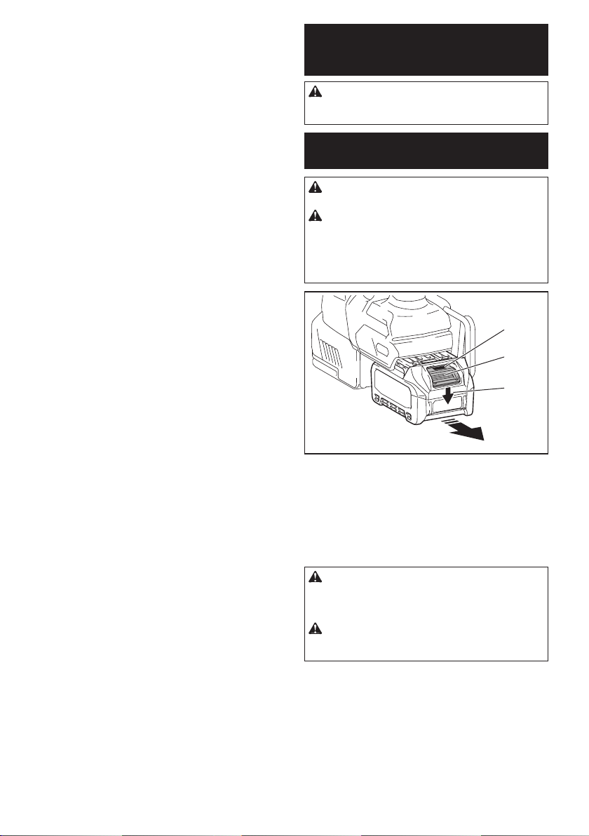
13. When opening the lid of the slot, avoid the
place where dust and water may come into the
slot. Always keep the inlet of the slot clean.
14. Always insert the wireless unit in the correct
direction.
15. Do not press the wireless activation button
on the wireless unit too hard and/or press the
button with an object with a sharp edge.
16. Always close the lid of the slot when
operating.
17. Do not remove the wireless unit from the slot
while the power is being supplied to the tool.
Doing so may cause a malfunction of the wireless
unit.
18. Do not remove the sticker on the wireless unit.
19. Do not put any sticker on the wireless unit.
20. Do not leave the wireless unit in a place where
static electricity or electrical noise could be
generated.
21. Do not leave the wireless unit in a place sub-
ject to high heat, such as a car sitting in the
sun.
22. Do not leave the wireless unit in a dusty or
powdery place or in a place corrosive gas
could be generated.
23. Sudden change of the temperature may bedew
the wireless unit. Do not use the wireless unit
until the dew is completely dried.
24. When cleaning the wireless unit, gently wipe
with a dry soft cloth. Do not use benzine, thin-
ner, conductive grease or the like.
25. When storing the wireless unit, keep it in the
supplied case or a static-free container.
26. Do not insert any devices other than Makita
wireless unit into the slot on the tool.
27. Do not use the tool with the lid of the slot dam-
aged. Water, dust, and dirt come into the slot may
cause malfunction.
28. Do not pull and/or twist the lid of the slot more
than necessary. Restore the lid if it comes off
from the tool.
29. Replace the lid of the slot if it is lost or
damaged.
SAVE THESE INSTRUCTIONS.
FUNCTIONAL
DESCRIPTION
CAUTION: Always be sure that the tool is
switched off and the battery cartridge is removed
before adjusting or checking function on the tool.
Installing or removing battery
cartridge
CAUTION: Always switch off the tool before
installing or removing of the battery cartridge.
CAUTION: Hold the tool and the battery car-
tridge rmly when installing or removing battery
cartridge. Failure to hold the tool and the battery
cartridge rmly may cause them to slip off your hands
and result in damage to the tool and battery cartridge
and a personal injury.
1
2
3
► 1. Red indicator 2. Button 3. Battery cartridge
To remove the battery cartridge, slide it from the tool
while sliding the button on the front of the cartridge.
To install the battery cartridge, align the tongue on the
battery cartridge with the groove in the housing and slip
it into place. Insert it all the way until it locks in place
with a little click. If you can see the red indicator on the
upper side of the button, it is not locked completely.
CAUTION: Always install the battery cartridge
fully until the red indicator cannot be seen. If not,
it may accidentally fall out of the tool, causing injury to
you or someone around you.
CAUTION: Do not install the battery cartridge
forcibly. If the cartridge does not slide in easily, it is
not being inserted correctly.
7 ENGLISH
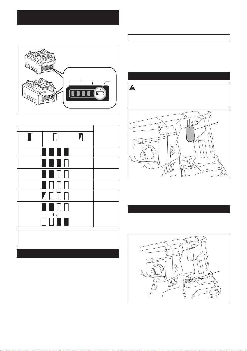
Indicating the remaining battery
capacity
Press the check button on the battery cartridge to indi-
cate the remaining battery capacity. The indicator lamps
light up for a few seconds.
1
2
► 1. Indicator lamps 2. Check button
Indicator lamps Remaining
capacity
Lighted Off Blinking
75% to 100%
50% to 75%
25% to 50%
0% to 25%
Charge the
battery.
The battery
may have
malfunctioned.
NOTE: Depending on the conditions of use and the
ambient temperature, the indication may differ slightly
from the actual capacity.
Tool / battery protection system
The tool is equipped with a tool/battery protection sys-
tem. This system automatically cuts off power to the
motor to extend tool and battery life. The tool will auto-
matically stop during operation if the tool or battery is
placed under one of the following conditions:
Overload protection
When the battery is operated in a manner that causes
it to draw an abnormally high current, the tool automat-
ically stops without any indication. In this situation, turn
the tool off and stop the application that caused the tool
to become overloaded. Then turn the tool on to restart.
Overheat protection
When the tool or battery is overheated, the tool stops
automatically. In this case, let the tool and battery cool
before turning the tool on again.
NOTE: When the tool is overheated, the lamp blinks.
Overdischarge protection
When the battery capacity is not enough, the tool stops
automatically. In this case, remove the battery from the
tool and charge the battery.
Switch action
WARNING: Before installing the battery car-
tridge into the tool, always check to see that the
switch trigger actuates properly and returns to
the "OFF" position when released.
1
► 1. Switch trigger
To start the tool, simply pull the switch trigger. Tool
speed is increased by increasing pressure on the switch
trigger. Release the switch trigger to stop.
Speed change
The revolutions and blows per minute can be adjusted
by turning the adjusting dial. The dial is marked 1 (low-
est speed) to 5 (full speed).
1
► 1. Adjusting dial
Refer to the table below for the relationship between the
number on the adjusting dial and the revolutions and
blows per minute.
8 ENGLISH
Number Revolutions per
minute
Blows per minute
5 980 5,000
4 870 4,440
3 630 3,210
2 380 1,940
1 300 1,530
CAUTION: Do not turn the adjusting dial when
the tool is running. Failure to do so may result in
the loss of control of the tool and cause an injury.
NOTICE: If the tool is operated continuously at
low speed for a long time, the motor will get over-
loaded, resulting in tool malfunction.
NOTICE: The speed adjusting dial can be turned
only as far as 5 and back to 1. Do not force it past
5 or 1, or the speed adjusting function may no
longer work.
NOTE: Soft no-load rotation function
When the speed adjusting dial is set to "4" or higher,
the tool automatically reduces the speed at no-load to
reduce the vibration under no-load. Once operation
starts with a bit against concrete, blows per minute
increase and reach the numbers as shown in the
table. When temperature is low and there is less
uidity in grease, the tool may not have this function
even with the motor rotating.
Lighting up the front lamp
1
► 1. Lamp
CAUTION: Do not look in the light or see the
source of light directly.
Pull the switch trigger to light up the lamp. The lamp
keeps on lighting while the switch trigger is being pulled.
The lamp goes out approximately 10 seconds after
releasing the switch trigger.
CAUTION: If the lamp goes off after blinking
for a few seconds, the active feedback sensing
technology is not working properly. Ask your
local Makita Service Center for repair.
NOTE: Use a dry cloth to wipe the dirt off the lens of
the lamp. Be careful not to scratch the lens of lamp, or
it may lower the illumination.
NOTE: If the dust collection system is installed on the
tool, the lamp of the dust collection system lights up
instead of the lamp of the tool.
Reversing switch action
1
AB
► 1. Reversing switch lever
CAUTION: Always check the direction of
rotation before operation.
CAUTION: Use the reversing switch only after
the tool comes to a complete stop. Changing the
direction of rotation before the tool stops may dam-
age the tool.
CAUTION: When not operating the tool,
always set the reversing switch lever to the neu-
tral position.
This tool has a reversing switch to change the direction
of rotation. Depress the reversing switch lever from the
A side for clockwise rotation or from the B side for coun-
terclockwise rotation.
When the reversing switch lever is in the neutral posi-
tion, the switch trigger cannot be pulled.
Changing the quick change chuck
for SDS-plus
For GRH02
The quick change chuck for SDS-plus can be easily
exchanged for the quick change drill chuck.
9 ENGLISH
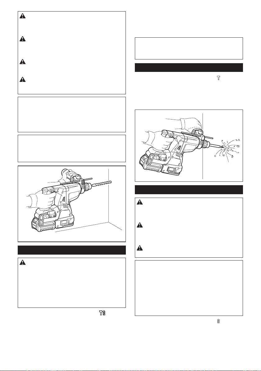
Removing the quick change chuck
for SDS-plus
CAUTION: Before removing the quick change
chuck for SDS-plus, be sure to remove the bit.
Grasp the change cover of the quick change chuck for
SDS-plus and turn in the direction of the arrow until
the change cover line moves from the
symbol to
the
symbol. Pull forcefully in the direction of the arrow.
1 2
3
► 1. Quick change chuck for SDS-plus 2. Change
cover 3. Change cover line
Installing the quick change drill chuck
Check the line of the quick change drill chuck shows
the
symbol. Grasp the change cover of the quick
change drill chuck and set the line to the
symbol.
Place the quick change drill chuck on the spindle of the
tool. Grasp the change cover of the quick change drill
chuck and turn the change cover line to the
symbol
until a click can clearly be heard.
1 2
3 4
► 1. Quick change drill chuck 2. Spindle 3. Change
cover line 4. Change cover
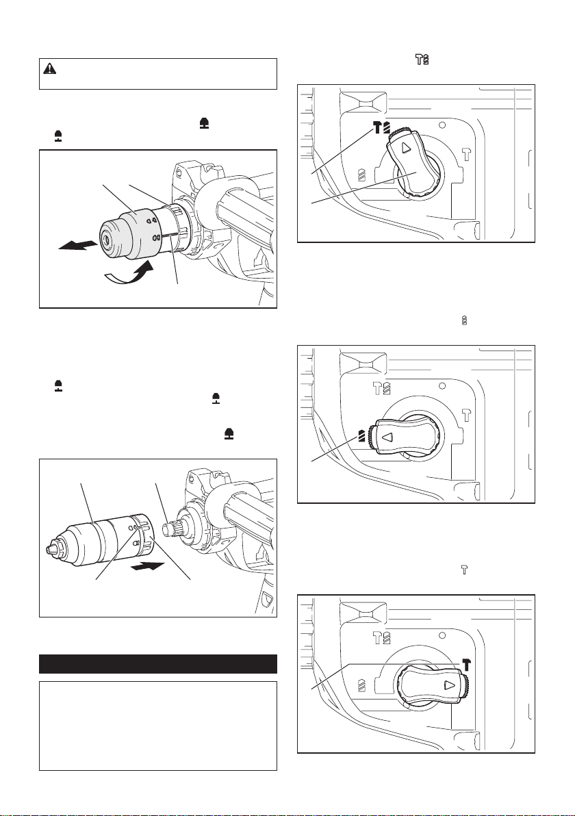
Selecting the action mode
NOTICE: Do not rotate the action mode chang-
ing knob when the tool is running. The tool will be
damaged.
NOTICE: To avoid rapid wear on the mode
change mechanism, be sure that the action mode
changing knob is always positively located in one
of the three action mode positions.
Rotation with hammering
For drilling in concrete, masonry, etc., rotate the action
mode changing knob to the
symbol. Use a tungsten-
carbide tipped bit (optional accessory).
1
2
► 1. Rotation with hammering 2. Action mode chang-
ing knob
Rotation only
For drilling in wood, metal or plastic materials, rotate
the action mode changing knob to the
symbol. Use a
twist drill bit or wood drill bit.
1
► 1. Rotation only
Hammering only
For chipping, scaling or demolition operations, rotate
the action mode changing knob to the
symbol. Use a
bull point, cold chisel, scaling chisel, etc.
1
► 1. Hammering only
10 ENGLISH
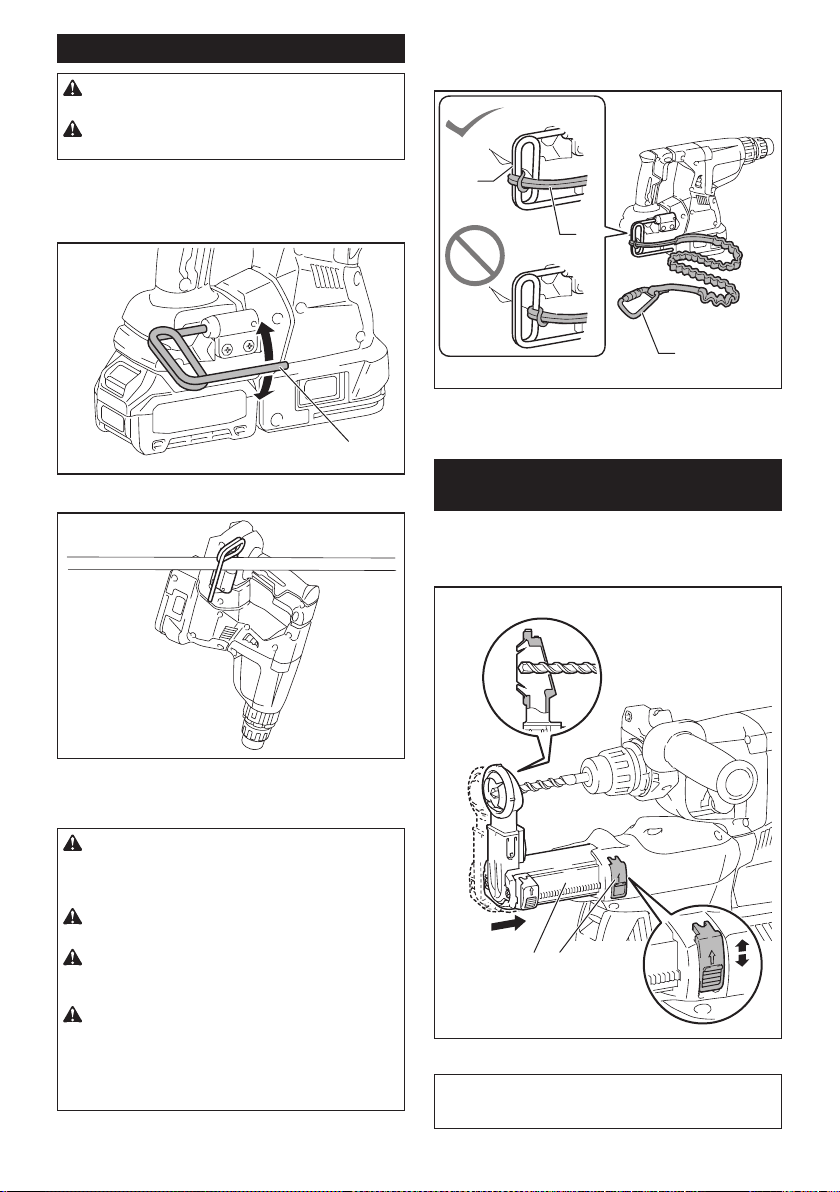
Hook
CAUTION: Always remove the battery when
hanging the tool with the hook.
CAUTION: Never hook the tool at high loca-
tion or on potentially unstable surface.
The hook is convenient for temporarily hanging the tool.
To use the hook, simply lift up hook until it snaps into
the open position. When not in use, always lower hook
until it snaps into the closed position.
1
► 1. Hook
Connecting lanyard (tether strap) to
the hook
CAUTION: Do not use damaged hook and
screws. Before use, always check for damages,
cracks or deformations, and make sure that the
screws are tightened.
CAUTION: Make sure that the hook is
securely installed with the screws.
CAUTION: Do not remove the battery car-
tridge while hanging the tool. The tool may fall if the
screws are not tightened.
CAUTION: Always use a locking carabiner
(multi-action and screw gate type) and be sure
to attach the lanyard (tether strap) to the double
looped portion of the hook. Improper attachment
may cause tool drop from the hook and result in
personal injury.
The hook is also used for connecting the lanyard (tether
strap). Be sure to connect the lanyard (tether strap) to
the double looped portion of the hook.
1
2
3
► 1. Double looped portion of the hook 2. Lanyard
(tether strap) 3. Locking carabiner (multi-action and
screw gate type)
Adjusting the nozzle position of the
dust collection system
Optional accessory
Push in the guide while pushing up the guide adjustment
button, and then release the button at the desired position.
1 2
► 1. Guide 2. Guide adjustment button
NOTE: Before adjusting the nozzle position, release
the nozzle forward completely by pushing up the
guide adjustment button.
11 ENGLISH
If a long drill bit is installed, extend the guide by pushing
up the extension button.
1
► 1. Extension button
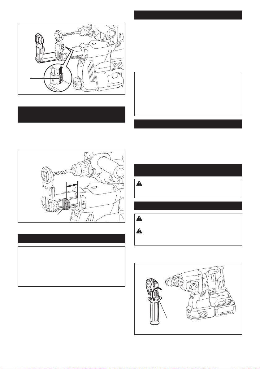
Adjusting the drilling depth of the
dust collection system
Optional accessory
Slide the depth adjustment button to the desired posi-
tion while pushing it up. The distance (A) is the drilling
depth.
1
A
► 1. Depth adjustment button
Torque limiter
NOTICE: As soon as the torque limiter actuates,
switch off the tool immediately. This will help pre-
vent premature wear of the tool.
NOTICE: Drill bits such as hole saw, which tend
to pinch or catch easily in the hole, are not appro-
priate for this tool. This is because they will cause
the torque limiter to actuate too frequently.
The torque limiter will actuate when a certain torque
level is reached. The motor will disengage from the
output shaft. When this happens, the drill bit will stop
turning.
Electronic function
The tool is equipped with the electronic functions for
easy operation.
• Constant speed control
The speed control function provides the constant
rotation speed regardless of load conditions.
• Active Feedback sensing Technology
If the tool is swung at the predetermined accelera-
tion during operation, the motor is forcibly stopped
to reduce the burden on the wrist.
NOTE: This function does not work if the acceleration
does not reach the predetermined one when the tool
is swung.
NOTE: If the bit is swung at the predetermined
acceleration during chipping, scaling, or demolishing,
the motor is forcibly stopped. In this case, release
the switch trigger, and then pull the switch trigger to
restart the tool.
Electric brake
This tool is equipped with an electric brake. If the tool
consistently fails to quickly stop after the switch trigger
is released, have the tool serviced at a Makita service
center.
ASSEMBLY
CAUTION: Always be sure that the tool is
switched off and the battery cartridge is removed
before carrying out any work on the tool.
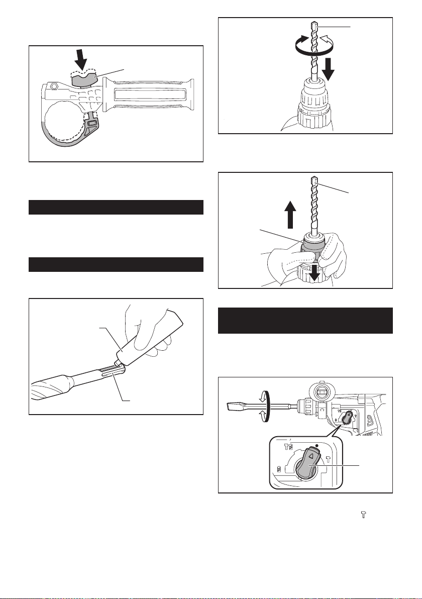
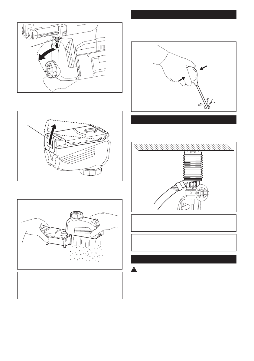
Side grip (auxiliary handle)
CAUTION: Always use the side grip to ensure
safe operation.
CAUTION: After installing or adjusting the
side grip, make sure that the side grip is rmly
secured.
To install the side grip, follow the steps below.
1. Loosen the thumb screw on the side grip.
1
► 1. Thumb screw
12 ENGLISH
2. Attach the side grip while pressing the thumb
screw so that the grooves on the grip t in the protru-
sions on the tool barrel.
1
► 1. Thumb screw
3. Tighten the thumb screw to secure the grip. The
grip can be xed at desired angle.
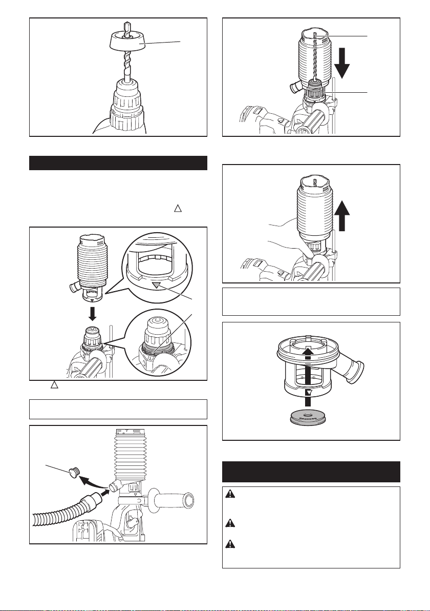
Grease
Coat the shank end of the drill bit beforehand with a
small amount of grease (about 0.5 - 1 g).
This chuck lubrication assures smooth action and lon-
ger service life.
Installing or removing drill bit
Clean the shank end of the drill bit and apply grease
before installing the drill bit.
1
2
► 1. Shank end 2. Grease
Insert the drill bit into the tool. Turn the drill bit and push
it in until it engages.
After installing the drill bit, always make sure that the
drill bit is securely held in place by trying to pull it out.
1
► 1. Drill bit
To remove the drill bit, pull the chuck cover down all the
way and pull the drill bit out.
1
2
► 1. Drill bit 2. Chuck cover
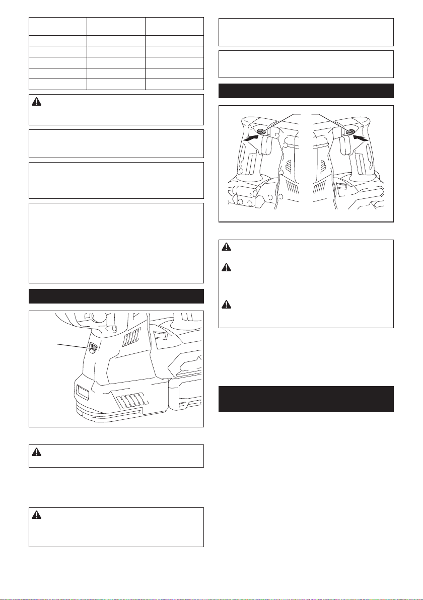
Chisel angle (when chipping,
scaling or demolishing)
The chisel can be secured at the desired angle. To
change the chisel angle, rotate the action mode chang-
ing knob to the O symbol. Turn the chisel to the desired
angle.
1
► 1. Action mode changing knob
Rotate the action mode changing knob to the
sym-
bol. Then make sure that the chisel is securely held in
place by turning it slightly.
13 ENGLISH
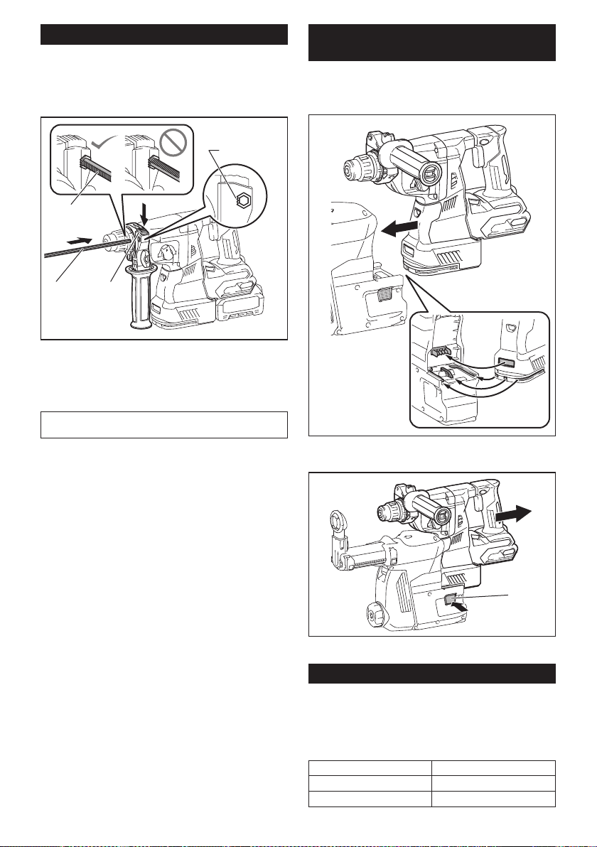
Depth gauge
The depth gauge is convenient for drilling holes of
uniform depth.
Press and hold the lock button, and then insert the
depth gauge into the hex hole. Make sure that the
toothed side of the depth gauge faces the marking.
3
4
1 2
► 1. Depth gauge 2. Lock button 3. Marking
4. Toothed side
Adjust the depth gauge by moving it back and forth
while pressing the lock button. After the adjustment,
release the lock button to lock the depth gauge.
NOTE: Make sure that the depth gauge does not
touch the main body of the tool when attaching it.
Installing or removing the dust
collection system
Optional accessory
To install the dust collection system, insert the tool into the dust collec-
tion system all the way until it locks in place with a little double click.
To remove the dust collection system, pull the tool while
pressing the lock-off button.
1
► 1. Lock-off button
Dust cup
Optional accessory
Use the dust cup to prevent dust from falling over the tool and
on yourself when performing overhead drilling operations.
Attach the dust cup to the bit as shown in the gure. The size
of bits which the dust cup can be attached to is as follows.
Model Bit diameter
Dust cup 5 6 mm (1/4") - 14.5 mm (9/16")
Dust cup 9 12 mm (15/32") - 16 mm (5/8")
14 ENGLISH
1
► 1. Dust cup
Dust cup set
Optional accessory
Before installing the dust cup set, remove the bit from
the tool if installed.
Install the dust cup set on the tool so that the
sym-
bol on the dust cup is aligned with the groove in the tool.
2
1
► 1. symbol 2. Groove
NOTE: If you connect a vacuum cleaner to the dust
cup set, remove the dust cap before connecting it.
1
► 1. Dust cap
To remove the dust cup set, remove the bit while pulling
the chuck cover in the direction of the arrow.
1
2
► 1. Bit 2. Chuck cover
Hold the root of dust cup and pull it out.
NOTE: If the cap comes off from the dust cup, attach
it with its printed side facing up so that groove on the
cap ts in the inside periphery of the attachment.
OPERATION
CAUTION: Always use the side grip (auxiliary
handle) and rmly hold the tool by both side grip
and switch handle during operations.
CAUTION: Always make sure that the work-
piece is secured before operation.
CAUTION: Do not pull the tool out forcibly
even the bit gets stuck. Loss of control may
cause injury.
15 ENGLISH
CAUTION: The dust collection system is
intended for drilling in concrete only. Do not use
the dust collection system for drilling in metal or
wood.
CAUTION: When using the tool with the dust
collection system, be sure to attach the lter
to the dust collection system to prevent dust
inhalation.
CAUTION: Before using the dust collection
system, check that the lter is not damaged.
Failure to do so may cause dust inhalation.
CAUTION: The dust collection system col-
lects the generated dust at a considerable rate,
but not all dust can be collected.
NOTICE: Do not use the dust collection system
for core drilling or chiseling.
NOTICE: Do not use the dust collection system
for drilling in wet concrete or use this system
in wet environment. Failure to do so may cause
malfunction.
NOTE: If the battery cartridge is in low temperature,
the tool’s capability may not be fully obtained. In this
case, warm up the battery cartridge by using the
tool with no load for a while to fully obtain the tool’s
capability.
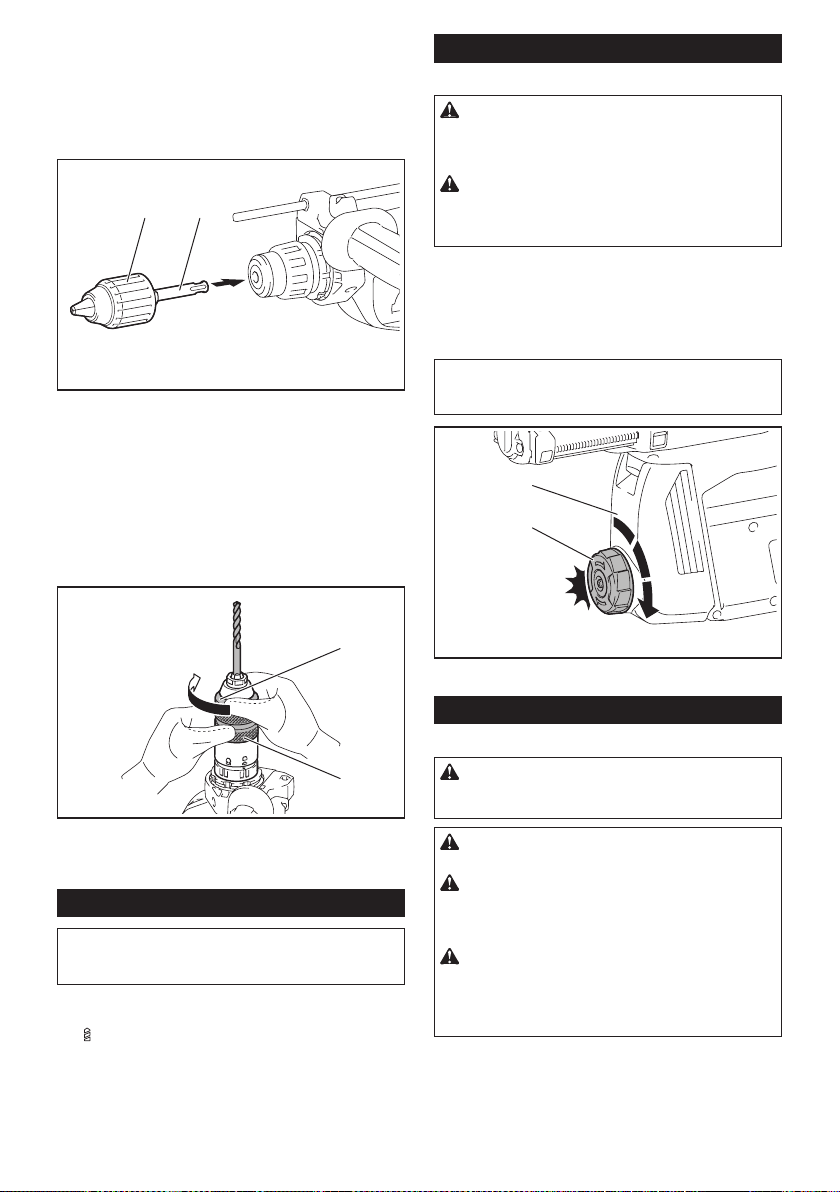
Hammer drilling operation
CAUTION: There is tremendous and sudden
twisting force exerted on the tool/drill bit at the time of
hole break-through, when the hole becomes clogged
with chips and particles, or when striking reinforcing
rods embedded in the concrete. Always use the side
grip (auxiliary handle) and rmly hold the tool by
both side grip and switch handle during opera-
tions. Failure to do so may result in the loss of control
of the tool and potentially severe injury.
Set the action mode changing knob to the symbol.
Position the drill bit at the desired location for the hole,
then pull the switch trigger. Do not force the tool. Light
pressure gives best results. Keep the tool in position
and prevent it from slipping away from the hole.
Do not apply more pressure when the hole becomes
clogged with chips or particles. Instead, run the tool at
an idle, then remove the drill bit partially from the hole.
By repeating this several times, the hole will be cleaned
out and normal drilling may be resumed.
NOTE: Eccentricity in the drill bit rotation may occur
while operating the tool with no load. The tool auto-
matically centers itself during operation. This does not
affect the drilling precision.
Chipping/Scaling/Demolition
Set the action mode changing knob to the symbol.
Hold the tool rmly with both hands. Turn the tool on
and apply slight pressure on the tool so that the tool will
not bounce around, uncontrolled.
Pressing very hard on the tool will not increase the
efciency.
Drilling in wood or metal
CAUTION: Hold the tool rmly and exert care
when the drill bit begins to break through the
workpiece. There is a tremendous force exerted on
the tool/drill bit at the time of hole break through.
CAUTION: A stuck drill bit can be removed
simply by setting the reversing switch to reverse
rotation in order to back out. However, the tool
may back out abruptly if you do not hold it rmly.
CAUTION: Always secure workpieces in a
vise or similar hold-down device.
NOTICE: Never use “rotation with hammering”
when the drill chuck is installed on the tool. The
drill chuck may be damaged.
Also, the drill chuck will come off when reversing the
tool.
NOTICE: Pressing excessively on the tool will
not speed up the drilling. In fact, this excessive
pressure will only serve to damage the tip of your drill
bit, decrease the tool performance and shorten the
service life of the tool.
Set the action mode changing knob to the symbol.
16 ENGLISH
For GRH01
Optional accessory
Attach the chuck adapter to a keyless drill chuck to
which 1/2"-20 size screw can be installed, and then
install them to the tool. When installing it, refer to the
section “Installing or removing drill bit”.
1 2
► 1. Keyless drill chuck 2. Chuck adapter
For GRH02
Use the quick change drill chuck as standard equip-
ment. When installing it, refer to "changing the quick
change chuck for SDS-plus".
Hold the ring and turn the sleeve counterclockwise to
open the chuck jaws. Place the bit in the chuck as far as
it will go. Hold the ring rmly and turn the sleeve clock-
wise to tighten the chuck.
1
2
► 1. Sleeve 2. Ring
To remove the bit, hold the ring and turn the sleeve
counterclockwise.
Diamond core drilling
NOTICE: If performing diamond core drilling
operations using “rotation with hammering”
action, the diamond core bit may be damaged.
When performing diamond core drilling opera-
tions, always set the action mode changing knob to
the
position to use "rotation only" action.
Beating dust on the lter
Optional accessory
CAUTION: Do not turn the dial on the dust
case while the dust case is removed from the
dust collection system. Doing so may cause dust
inhalation.
CAUTION: Always switch off the tool when
turning the dial on the dust case. Turning the dial
while the tool is running may result in the loss of
control of the tool.
By beating the dust on the lter inside the dust case,
you can keep the vacuum efciency and also reduce
the number of times to dispose of the dust.
Turn the dial on the dust case three times after col-
lecting every 50,000 mm
3
of dust or when you feel the
vacuum performance declined.
NOTE: 50,000 mm
3
of dust equivalents to drilling 10
holes of ø10 mm and 65 mm depth (14 holes of ø3/8″
and 2″ depth).
2
1
► 1. Dust case 2. Dial
Disposing of dust
Optional accessory
CAUTION: Always be sure that the tool is
switched off and the battery cartridge is removed
before carrying out any work on the tool.
CAUTION: Be sure to wear dust mask when
disposing of dust.
CAUTION: Empty the dust case regularly
before the dust case becomes full. Failure to do so
may decrease the dust collection performance and
cause dust inhalation.
CAUTION: The performance of dust collection
decreases if the lter in the dust case become
clogged. Replace the lter with new one after
approximately 200 times of dust fulllment as a
guide. Failure to do so may cause dust inhalation.
17 ENGLISH
1. Remove the dust case while pressing down the
lever of the dust case.
1
► 1. Lever
2. Open the cover of the dust case.
1
► 1. Cover
3. Dispose of the dust, and then clean the lter.
NOTICE: When cleaning the lter, tap the case
of the lter gently by hand to remove dust. Do not
tap the lter directly; touch the lter with brush
or similar; or blow compressed air on the lter.
Doing so may damage the lter.
Blow-out bulb
Optional accessory
After drilling the hole, use the blow-out bulb to clean the
dust out of the hole.
Using dust cup set
Optional accessory
Fit the dust cup set against the ceiling when operating the tool.
NOTICE:
Do not use the dust cup set when drilling in
metal or similar. It may damage the dust cup set due to
the heat produced by small metal dust or similar.
NOTICE: Do not install or remove the dust cup
set with the drill bit installed in the tool. It may
damage the dust cup set and cause dust leak.
Connecting lanyard (tether strap) to the hook
Safety warnings specic for use at height
Read all safety warnings and instructions. Failure to follow
the warnings and instructions may result in serious injury.
1.
Always keep the tool tethered when working "at
height". Maximum lanyard length is 2 m (6.5 ft).
The maximum permissible fall height for lan-
yard (tether strap) must not exceed 2 m (6.5 ft).
2. Use only with lanyards appropriate for this tool
type and rated for at least 8.0 kg (17.6 lbs).
3. Do not anchor the tool lanyard to anything on
your body or on movable components. Anchor
the tool lanyard to a rigid structure that can
withstand the forces of a dropped tool.
4. Make sure the lanyard is properly secured at
each end prior to use.
18 ENGLISH
5. Inspect the tool and lanyard before each use
for damage and proper function (including
fabric and stitching). Do not use if damaged or
not functioning properly.
6. Do not wrap lanyards around or allow them to
come in contact with sharp or rough edges.
7.
Fasten the other end of the lanyard outside the
working area so that a falling tool is held securely.
8.
Attach the lanyard so that the tool will move away
from the operator if it falls. Dropped tools will swing on
the lanyard, which could cause injury or loss of balance.
9. Do not use near moving parts or running
machinery. Failure to do so may result in a crush
or entanglement hazard.
10. Do not carry the tool by the attachment device
or the lanyard.
11. Only transfer the tool between your hands
while you are properly balanced.
12. Do not attach lanyards to the tool in a way that
keeps switches or trigger-lock (if supplied)
from operating properly.
13. Avoid getting tangled in the lanyard.
14.
Keep lanyard away from the drilling area of the tool.
15. Use a locking carabiner (multi-action and
screw gate type). Do not use single action
spring clip carabiners.
16. In the event the tool is dropped, it must be
tagged and removed from service, and should
be inspected by a Makita Factory or Authorized
Service Center.
WIRELESS ACTIVATION
FUNCTION
What you can do with the wireless
activation function
The wireless activation function enables clean and com-
fortable operation. By connecting a supported vacuum
cleaner to the tool, you can run the vacuum cleaner
automatically along with the switch operation of the tool.
To use the wireless activation function, prepare following items:
• A wireless unit (optional accessory)
• A vacuum cleaner which supports the wireless
activation function
The overview of the wireless activation function
setting is as follows. Refer to each section for detail
procedures.
1. Installing the wireless unit
2. Tool registration for the vacuum cleaner
3. Starting the wireless activation function
Installing the wireless unit
Optional accessory
CAUTION: Place the tool on a at and stable
surface when installing the wireless unit.
NOTICE: Clean the dust and dirt on the tool
before installing the wireless unit. Dust or dirt
may cause malfunction if it comes into the slot of the
wireless unit.
NOTICE: To prevent the malfunction caused by
static, touch a static discharging material, such
as a metal part of the tool, before picking up the
wireless unit.
NOTICE: When installing the wireless unit,
always be sure that the wireless unit is inserted
in the correct direction and the lid is completely
closed.
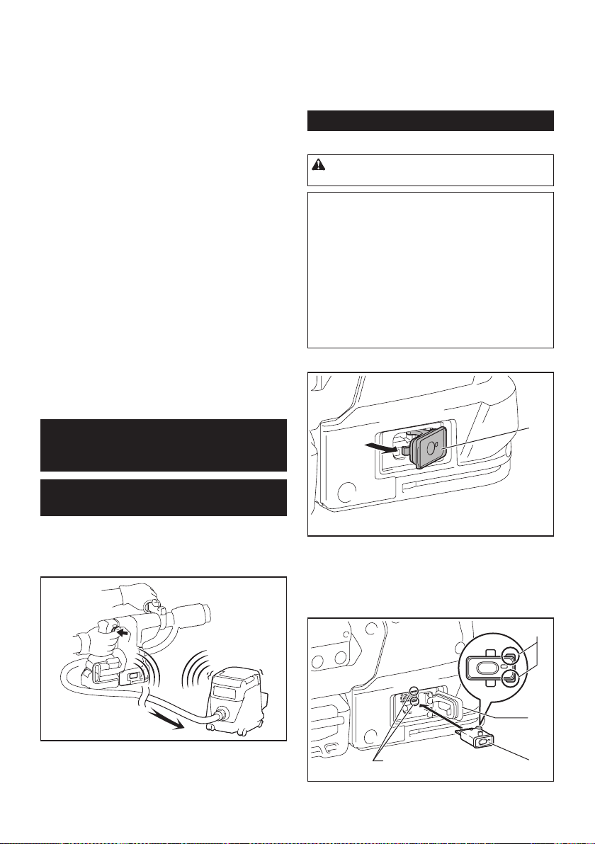
1. Open the lid on the tool as shown in the gure.
1
► 1. Lid
2. Insert the wireless unit to the slot and then close
the lid.
When inserting the wireless unit, align the projections
with the recessed portions on the slot.
3
1
4
2
► 1. Wireless unit 2. Projection 3. Lid 4. Recessed
portion
19 ENGLISH
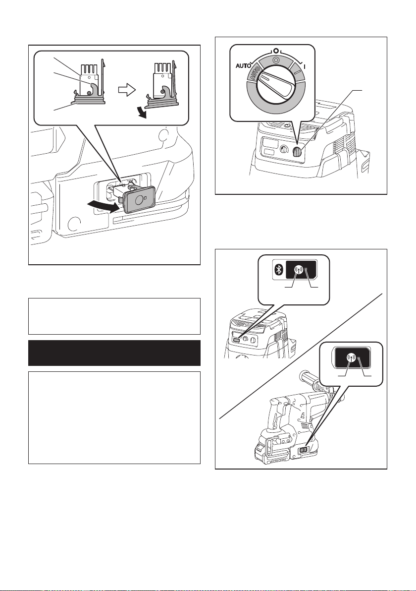
When removing the wireless unit, open the lid slowly.
The hooks on the back of the lid will lift the wireless unit
as you pull up the lid.
1
2
3
► 1. Wireless unit 2. Hook 3. Lid
After removing the wireless unit, keep it in the supplied
case or a static-free container.
NOTICE: Always use the hooks on the back of
the lid when removing the wireless unit. If the
hooks do not catch the wireless unit, close the lid
completely and open it slowly again.
Tool registration for the vacuum
cleaner
NOTE: A Makita vacuum cleaner supporting the
wireless activation function is required for the tool
registration.
NOTE: Finish installing the wireless unit to the tool
before starting the tool registration.
NOTE: During the tool registration, do not pull the
switch trigger or turn on the power switch on the
vacuum cleaner.
NOTE: Refer to the instruction manual of the vacuum
cleaner, too.
If you wish to activate the vacuum cleaner along with
the switch operation of the tool, nish the tool registra-
tion beforehand.
1. Install the batteries to the vacuum cleaner and the
tool.
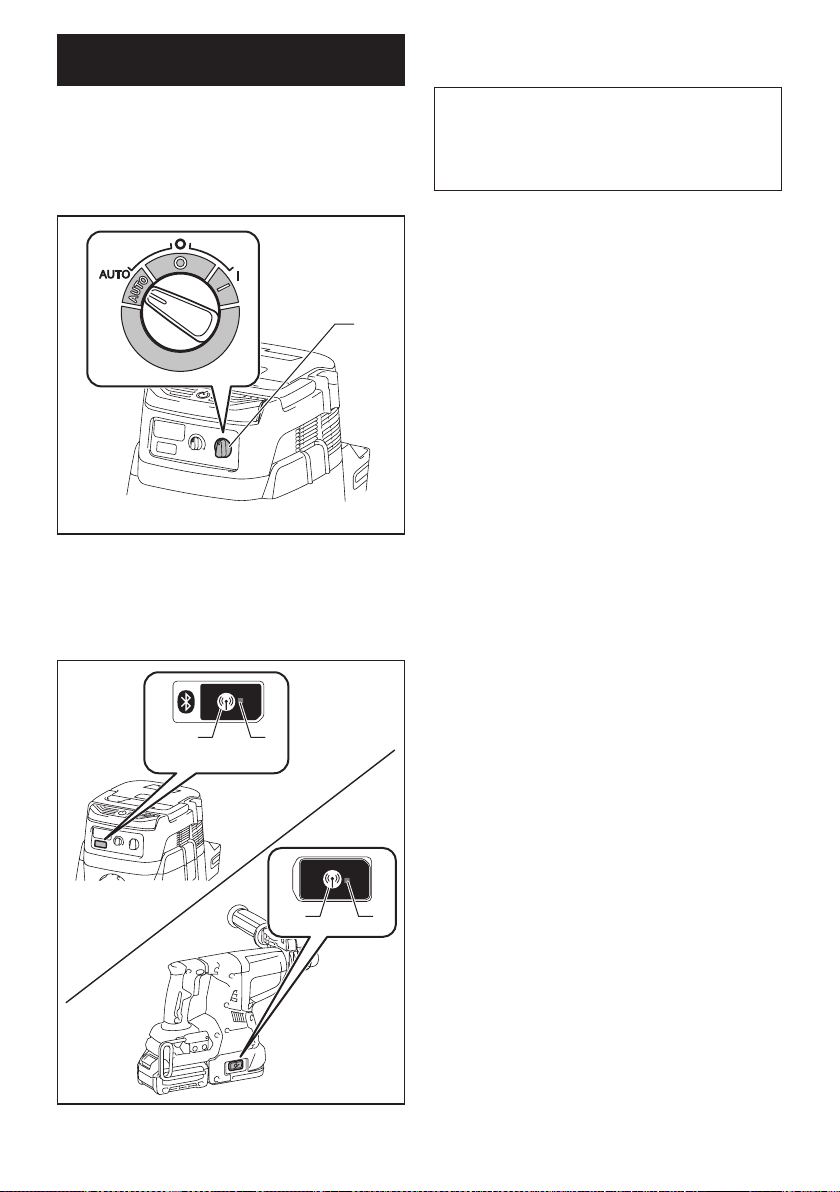
2. Set the stand-by switch on the vacuum cleaner to
"AUTO".
1
► 1. Stand-by switch
3. Press the wireless activation button on the vac-
uum cleaner for 3 seconds until the wireless activation
lamp blinks in green. And then press the wireless acti-
vation button on the tool in the same way.
12
12
► 1. Wireless activation button 2. Wireless activation
lamp
If the vacuum cleaner and the tool are linked success-
fully, the wireless activation lamps will light up in green
for 2 seconds and start blinking in blue.
20 ENGLISH
NOTE: The wireless activation lamps nish blinking
in green after 20 seconds elapsed. Press the wireless
activation button on the tool while the wireless acti-
vation lamp on the cleaner is blinking. If the wireless
activation lamp does not blink in green, push the wire-
less activation button briey and hold it down again.
NOTE: When performing two or more tool registra-
tions for one vacuum cleaner, nish the tool registra-
tion one by one.
Starting the wireless activation
function
NOTE: Finish the tool registration for the vacuum
cleaner prior to the wireless activation.
NOTE: Refer to the instruction manual of the vacuum
cleaner, too.
After registering a tool to the vacuum cleaner, the
vacuum cleaner will automatically runs along with the
switch operation of the tool.
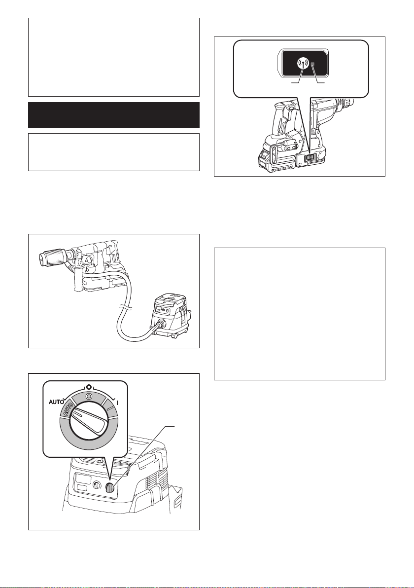
1. Install the wireless unit to the tool.
2. Connect the hose of the vacuum cleaner with the
tool.
3. Set the stand-by switch on the vacuum cleaner to
"AUTO".
1
► 1. Stand-by switch
4. Push the wireless activation button on the tool
briey. The wireless activation lamp will blink in blue.
12
► 1. Wireless activation button 2. Wireless activation
lamp
5. Pull the switch trigger of the tool. Check if the
vacuum cleaner runs while the switch trigger is being
pulled.
To stop the wireless activation of the vacuum cleaner,
push the wireless activation button on the tool.
NOTE: The wireless activation lamp on the tool will
stop blinking in blue when there is no operation for
2 hours. In this case, set the stand-by switch on the
vacuum cleaner to "AUTO" and push the wireless
activation button on the tool again.
NOTE: The vacuum cleaner starts/stops with a delay.
There is a time lag when the vacuum cleaner detects
a switch operation of the tool.
NOTE: The transmission distance of the wireless unit
may vary depending on the location and surrounding
circumstances.
NOTE: When two or more tools are registered to one
vacuum cleaner, the vacuum cleaner may start run-
ning even if you don't pull the switch trigger because
another user is using the wireless activation function.
21 ENGLISH
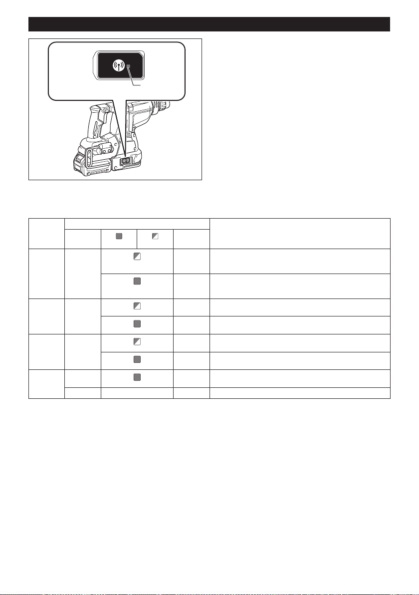
Description of the wireless activation lamp status
1
► 1. Wireless activation lamp
The wireless activation lamp shows the status of the wireless activation function. Refer to the table below for the
meaning of the lamp status.
Status Wireless activation lamp Description
Color
On
Blinking
Duration
Standby Blue
2 hours The wireless activation of the vacuum cleaner is available. The
lamp will automatically turn off when no operation is performed
for 2 hours.
When
the tool is
running.
The wireless activation of the vacuum cleaner is available and the
tool is running.
Tool
registration
Green
20 seconds Ready for the tool registration. Waiting for the registration by the
vacuum cleaner.
2 seconds The tool registration has been nished. The wireless activation
lamp will start blinking in blue.
Cancelling
tool
registration
Red
20 seconds Ready for the cancellation of the tool registration. Waiting for the
cancellation by the vacuum cleaner.
2 seconds The cancellation of the tool registration has been nished. The
wireless activation lamp will start blinking in blue.
Others Red
3 seconds The power is supplied to the wireless unit and the wireless activa-
tion function is starting up.
Off - - The wireless activation of the vacuum cleaner is stopped.
22 ENGLISH
Cancelling tool registration for the
vacuum cleaner
Perform the following procedure when cancelling the
tool registration for the vacuum cleaner.
1. Install the batteries to the vacuum cleaner and the
tool.
2. Set the stand-by switch on the vacuum cleaner to
"AUTO".
1
► 1. Stand-by switch
3. Press the wireless activation button on the vac-
uum cleaner for 6 seconds. The wireless activation
lamp blinks in green and then become red. After that,
press the wireless activation button on the tool in the
same way.
12
12
► 1. Wireless activation button 2. Wireless activation
lamp
If the cancellation is performed successfully, the wire-
less activation lamps will light up in red for 2 seconds
and start blinking in blue.
NOTE: The wireless activation lamps nish blinking in
red after 20 seconds elapsed. Press the wireless acti-
vation button on the tool while the wireless activation
lamp on the cleaner is blinking. If the wireless acti-
vation lamp does not blink in red, push the wireless
activation button briey and hold it down again.

23 ENGLISH
Troubleshooting for wireless activation function
Before asking for repairs, conduct your own inspection rst. If you nd a problem that is not explained in the manual,
do not attempt to dismantle the tool. Instead, ask Makita Authorized Service Centers, always using Makita replace-
ment parts for repairs.
State of abnormality Probable cause (malfunction) Remedy
The wireless activation lamp does
not light/blink.
The wireless unit is not installed into the tool.
The wireless unit is improperly installed
into the tool.
Install the wireless unit correctly.
The terminal of the wireless unit and/or
the slot is dirty.
Gently wipe off dust and dirt on the terminal of the
wireless unit and clean the slot.
The wireless activation button on the
tool has not been pushed.
Push the wireless activation button on the tool
briey.
The stand-by switch on the vacuum
cleaner is not set to "AUTO".
Set the stand-by switch on the vacuum cleaner to
"AUTO".
No power supply
Supply the power to the tool and the vacuum cleaner.
Cannot nish tool registration / can-
celling tool registration successfully.
The wireless unit is not installed into the tool.
The wireless unit is improperly installed
into the tool.
Install the wireless unit correctly.
The terminal of the wireless unit and/or
the slot is dirty.
Gently wipe off dust and dirt on the terminal of the
wireless unit and clean the slot.
The stand-by switch on the vacuum
cleaner is not set to "AUTO".
Set the stand-by switch on the vacuum cleaner to
"AUTO".
No power supply
Supply the power to the tool and the vacuum cleaner.
Incorrect operation
Push the wireless activation button briey and perform
the tool registration/cancellation procedures again.
The tool and vacuum cleaner are away
from each other (out of the transmission
range).
Get the tool and vacuum cleaner closer to each
other. The maximum transmission distance is
approximately 10 m however it may vary according
to the circumstances.
Before nishing the tool registration/cancellation;
- the switch trigger on the tool is pulled or;
- the power button on the vacuum
cleaner is turned on.
Push the wireless activation button briey and
perform the tool registration/cancellation procedures
again.
The tool registration procedures for the
tool or vacuum cleaner have not nished.
Perform the tool registration procedures for both the
tool and the vacuum cleaner at the same timing.
Radio disturbance by other appliances
which generate high-intensity radio
waves.
Keep the tool and vacuum cleaner away from the
appliances such as Wi-Fi devices and microwave
ovens.
The vacuum cleaner does not run
along with the switch operation of
the tool.
The wireless unit is not installed into the tool.
The wireless unit is improperly installed
into the tool.
Install the wireless unit correctly.
The terminal of the wireless unit and/or
the slot is dirty.
Gently wipe off dust and dirt on the terminal of the
wireless unit and clean the slot.
The wireless activation button on the
tool has not been pushed.
Push the wireless activation button briey and make
sure that the wireless activation lamp is blinking in blue.
The stand-by switch on the vacuum
cleaner is not set to "AUTO".
Set the stand-by switch on the vacuum cleaner to
"AUTO".
More than 10 tools are registered to the
vacuum cleaner.
Perform the tool registration again.
If more than 10 tools are registered to the vacuum cleaner,
the tool registered earliest will be cancelled automatically.
The vacuum cleaner erased all tool
registrations.
Perform the tool registration again.
No power supply
Supply the power to the tool and the vacuum cleaner.
The tool and vacuum cleaner are away
from each other (out of the transmission
range).
Get the tool and vacuum cleaner closer each other. The
maximum transmission distance is approximately 10 m
however it may vary according to the circumstances.
Radio disturbance by other appliances
which generate high-intensity radio
waves.
Keep the tool and vacuum cleaner away from the
appliances such as Wi-Fi devices and microwave
ovens.
The vacuum cleaner runs while the
tool's switch trigger is not pulled.
Other users are using the wireless
activation of the vacuum cleaner with
their tools.
Turn off the wireless activation button of the other
tools or cancel the tool registration of the other
tools.
24 ENGLISH
MAINTENANCE
CAUTION: Always be sure that the tool is
switched off and the battery cartridge is removed
before attempting to perform inspection or
maintenance.
NOTICE: Never use gasoline, benzine, thinner,
alcohol or the like. Discoloration, deformation or
cracks may result.
To maintain product SAFETY and RELIABILITY,
repairs, any other maintenance or adjustment should
be performed by Makita Authorized or Factory Service
Centers, always using Makita replacement parts.
Replacing lter of dust case
Optional accessory
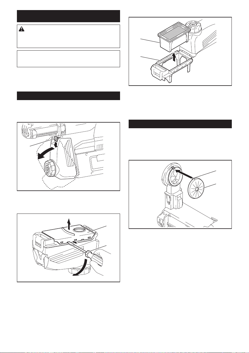
1. Remove the dust case while pressing down the
lever of the dust case.
1
► 1. Lever
2. Insert the at-blade screwdriver into the slots of
the lter cover to remove the lter cover.
2
1
► 1. Flat-blade screwdriver 2. Filter cover
3. Remove the lter from the lter case.
1
2
► 1. Filter 2. Filter case
4. Attach a new lter to the lter case, and then
attach the lter cover.
5. Close the cover of the dust case, and then attach
the dust case to the dust collection system.
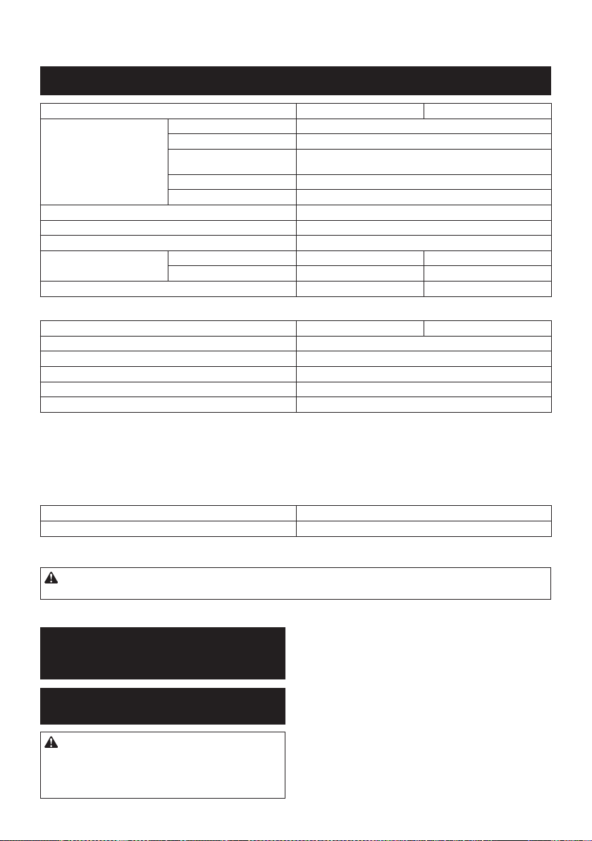
Replacing sealing cap
Optional accessory
If the sealing cap is worn out, the performance of the
dust collection decreases. Replace it if it's worn out.
Remove the sealing cap, and then attach a new one
with its protrusion facing upward.
1
2
► 1. Protrusion 2. Sealing cap

25 ENGLISH
OPTIONAL
ACCESSORIES
CAUTION: These accessories or attachments
are recommended for use with your Makita tool
specied in this manual. The use of any other
accessories or attachments might present a risk of
injury to persons. Only use accessory or attachment
for its stated purpose.
If you need any assistance for more details regard-
ing these accessories, ask your local Makita Service
Center.
• Carbide-tipped drill bits (SDS-Plus carbide-tipped
bits)
• Core bit
• Bull point
• Diamond core bit
• Cold chisel
• Scaling chisel
• Grooving chisel
• Chuck adapter
• Keyless drill chuck
• Bit grease
• Depth gauge
• Blow-out bulb
• Dust cup
• Dust cup set
• Hook set
• Dust case set
• Drill chuck set
• Filter set
• Tool holder set
• Joint set
• Dust collection system
• Wireless unit
• Makita genuine battery and charger
• Safety goggles
• Plastic carrying case
NOTE: Some items in the list may be included in the
tool package as standard accessories. They may
differ from country to country.
MAKITA LIMITED WARRANTY
Please refer to the annexed warranty sheet for the
most current warranty terms applicable to this product.
If annexed warranty sheet is not available, refer to the
warranty details set forth at below website for your
respective country.
United States of America: www.makitatools.com
Canada: www.makita.ca
Other countries: www.makita.com
26 ESPAÑOL
ESPAÑOL (Instrucciones originales)
ESPECIFICACIONES
Modelo: GRH01 GRH02
Capacidades Concreto 28 mm (1-1/8″)
Punta de corona 54 mm (2-1/8″)
Punta de corona de diamante
(tipo seco)
65 mm (2-9/16″)
Acero 13 mm (1/2″)
Madera 32 mm (1-1/4″)
Velocidad sin carga 0 r/min - 980 r/min
Golpes por minuto 0 gpm - 5 000 gpm
Tensión nominal 36 V - 40 V c.c. máx.
Longitud total con BL4025 358 mm (14-1/8″) 389 mm (15-1/4″)
con BL4040 373 mm (14-3/4″) 404 mm (15-7/8″)
Peso neto
3,9 kg - 4,6 kg (8,6 lbs - 10,1 lbs) 4,1 kg - 4,6 kg (9,0 lbs - 10,1 lbs)
Accesorio opcional
Modelo: DX12 (para el modelo GRH01) DX14 (para el modelo GRH02)
Desempeño de succión 350 l/min
Carrera de operación Hasta 190 mm (7-1/2″)
Broca apropiada Hasta 260 mm (10-1/4″)
Tensión nominal 36 V - 40 V c.c. máx.
Peso neto 1,6 kg (3,5 lbs)
• Debido a nuestro continuo programa de investigación y desarrollo, las especicaciones aquí incluidas están
sujetas a cambio sin previo aviso.
• Las especicaciones pueden variar de país a país.
• El peso puede variar en función de los accesorios, incluido el cartucho de batería. En la tabla se muestra la
combinación de peso más ligero y más pesado conforme al procedimiento 01/2014 de EPTA.
Cartucho de batería y cargador aplicables
Cartucho de batería BL4025/BL4040
Cargador DC40RA
• Algunos de los cartuchos de batería y cargadores enumerados arriba podrían no estar disponibles depen-
diendo de su área de residencia.
ADVERTENCIA: Use únicamente los cartuchos de batería y los cargadores indicados arriba. El uso de
cualquier otro cartucho de batería y cargador podría ocasionar una lesión y/o un incendio.
ADVERTENCIAS DE
SEGURIDAD
Advertencias generales de seguridad
para herramientas eléctricas
ADVERTENCIA:
Lea todas las advertencias de
seguridad, instrucciones, ilustraciones y especicaciones
suministradas con esta herramienta eléctrica. El no seguir
todas las instrucciones indicadas a continuación podría oca-
sionar una descarga eléctrica, incendio y/o lesiones graves.
Conserve todas las advertencias
e instrucciones como referencia
en el futuro.
En las advertencias, el término “herramienta eléctrica”
se reere a su herramienta eléctrica de funcionamiento
con conexión a la red eléctrica (con cableado eléctrico)
o herramienta eléctrica de funcionamiento a batería
(inalámbrica).
Seguridad en el área de trabajo
1. Mantenga el área de trabajo limpia y bien ilu-
minada. Las áreas oscuras o desordenadas son
propensas a accidentes.

27 ESPAÑOL
2. No utilice las herramientas eléctricas en
atmósferas explosivas, tal como en la presen-
cia de líquidos, gases o polvo inamables. Las
herramientas eléctricas crean chispas que pueden
prender fuego al polvo o los humos.
3. Mantenga a los niños y curiosos alejados
mientras utiliza una herramienta eléctrica. Las
distracciones le pueden hacer perder el control.
Seguridad eléctrica
1.
Las clavijas de conexión de las herramientas
eléctricas deberán encajar perfectamente en la
toma de corriente. No modique nunca la clavija
de conexión de ninguna forma. No utilice ninguna
clavija adaptadora con herramientas eléctricas
que tengan conexión a tierra (puesta a tierra). La
utilización de clavijas no modicadas y que encajen
perfectamente en la toma de corriente reducirá el
riesgo de que se produzca una descarga eléctrica.
2.
Evite tocar con el cuerpo supercies conecta-
das a tierra o puestas a tierra tales como tubos,
radiadores, cocinas y refrigeradores. Si su cuerpo
es puesto a tierra o conectado a tierra existirá un
mayor riesgo de que sufra una descarga eléctrica.
3. No exponga las herramientas eléctricas a la
lluvia ni a condiciones húmedas. La entrada de
agua en una herramienta eléctrica aumentará el
riesgo de que se produzca una descarga eléctrica.
4. No maltrate el cable. Nunca utilice el cable
para transportar, jalar o desconectar la herra-
mienta eléctrica. Mantenga el cable alejado del
calor, aceite, objetos cortantes o piezas móvi-
les. Los cables dañados o enredados aumentan
el riesgo de sufrir una descarga eléctrica.
5.
Cuando utilice una herramienta eléctrica en
exteriores, utilice un cable de extensión apro-
piado para uso en exteriores. La utilización de un
cable apropiado para uso en exteriores reducirá el
riesgo de que se produzca una descarga eléctrica.
6. Si no es posible evitar usar una herramienta
eléctrica en condiciones húmedas, utilice un
alimentador protegido con interruptor de cir-
cuito de falla a tierra (ICFT). El uso de un ICFT
reduce el riesgo de descarga eléctrica.
7. Las herramientas eléctricas pueden producir
campos electromagnéticos (CEM) que no son
dañinos para el usuario. Sin embargo, si los
usuarios tienen marcapasos y otros dispositivos
médicos similares, deberán consultar al fabricante
de su dispositivo y/o a su médico antes de operar
esta herramienta eléctrica.
Seguridad personal
1. Manténgase alerta, preste atención a lo que
está haciendo y utilice su sentido común
cuando opere una herramienta eléctrica. No
utilice una herramienta eléctrica cuando esté
cansado o bajo la inuencia de drogas, alco-
hol o medicamentos. Un momento de distracción
mientras opera las herramientas eléctricas puede
terminar en una lesión grave.
2. Use equipo de protección personal. Póngase
siempre protección para los ojos. El equipo
protector tal como máscara contra el polvo, zapa-
tos de seguridad antiderrapantes, casco rígido y
protección para oídos utilizado en las condiciones
apropiadas reducirá el riesgo de lesiones.
3.
Impida el encendido accidental. Asegúrese
de que el interruptor esté en la posición de
apagado antes de conectar a la alimentación
eléctrica y/o de colocar el cartucho de batería,
así como al levantar o cargar la herramienta.
Cargar las herramientas eléctricas con su dedo
en el interruptor o enchufarlas con el interruptor
encendido hace que los accidentes sean comunes.
4. Retire cualquier llave de ajuste o llave de
apriete antes de encender la herramienta. Una
llave de ajuste o llave de apriete que haya sido
dejada puesta en una parte giratoria de la herra-
mienta eléctrica puede ocasionar alguna lesión.
5.
No utilice la herramienta donde no alcance.
Mantenga los pies sobre suelo rme y el equilibrio
en todo momento. Esto permite un mejor control de
la herramienta eléctrica en situaciones inesperadas.
6. Use una vestimenta apropiada. No use ropa
suelta ni alhajas. Mantenga el cabello, la ropa
y los guantes alejados de las piezas móviles.
Las prendas de vestir holgadas, las alhajas y
el cabello largo suelto podrían engancharse en
estas piezas móviles.
7.
Si dispone de dispositivos para la conexión de
equipos de extracción y recolección de polvo,
asegúrese de conectarlos y utilizarlos debida-
mente. Hacer uso de la recolección de polvo puede
reducir los riesgos relacionados con el polvo.
8.
No permita que la familiaridad adquirida debido
al uso frecuente de las herramientas haga que se
sienta conado e ignore los principios de seguri-
dad de las herramientas. Un descuido podría oca-
sionar una lesión grave en una fracción de segundo.
9. Utilice siempre gafas protectoras para prote-
ger sus ojos de lesiones al usar herramientas
eléctricas. Las gafas deben cumplir con la
Norma ANSI Z87.1 en EUA.
Es responsabilidad del empleador imponer
el uso de equipos protectores de seguridad
apropiados a los operadores de la herramienta
y demás personas cerca del área de trabajo.
Mantenimiento y uso de la herramienta eléctrica
1. No fuerce la herramienta eléctrica. Utilice la
herramienta eléctrica correcta para su aplica-
ción. La herramienta eléctrica adecuada hará un
mejor trabajo y de forma más segura a la veloci-
dad para la que ha sido fabricada.
2. No utilice la herramienta eléctrica si el inte-
rruptor no la enciende y apaga. Cualquier
herramienta eléctrica que no pueda ser contro-
lada con el interruptor es peligrosa y debe ser
reemplazada.
3.
Desconecte la clavija de la fuente de alimenta-
ción y/o retire la batería de la herramienta eléc-
trica, en caso de ser removible, antes de realizar
ajustes, cambiar accesorios o almacenar las
herramientas eléctricas. Tales medidas de segu-
ridad preventivas reducirán el riesgo de poner en
marcha la herramienta eléctrica de forma accidental.
4. Guarde la herramienta eléctrica que no use
fuera del alcance de los niños y no permita
que las personas que no están familiarizadas
con ella o con las instrucciones la operen. Las
herramientas eléctricas son peligrosas en manos
de personas que no saben operarlas.

28 ESPAÑOL
5. Dé mantenimiento a las herramientas eléctri-
cas y los accesorios. Compruebe que no haya
piezas móviles desalineadas o estancadas,
piezas rotas y cualquier otra condición que
pueda afectar al funcionamiento de la herra-
mienta eléctrica. Si la herramienta eléctrica
está dañada, haga que la reparen antes de
utilizarla. Muchos de los accidentes son ocasio-
nados por no dar un mantenimiento adecuado a
las herramientas eléctricas.
6. Mantenga las herramientas de corte limpias
y losas. Si recibe un mantenimiento adecuado
y tiene los bordes alados, es probable que la
herramienta se atasque menos y sea más fácil
controlarla.
7. Utilice la herramienta eléctrica, los accesorios
y las brocas de acuerdo con estas instruccio-
nes, considerando las condiciones laborales
y el trabajo a realizar. Si utiliza la herramienta
eléctrica para realizar operaciones distintas de
las indicadas, podrá presentarse una situación
peligrosa.
8. Mantenga los mangos y supercies de asi-
miento secos, limpios y libres de aceite o
grasa. Los mangos y supercies de asimiento
resbalosos no permiten una manipulación segura
ni el control de la herramienta en situaciones
inesperadas.
9. Cuando vaya a utilizar esta herramienta, evite
usar guantes de trabajo de tela ya que éstos
podrían atorarse. Si los guantes de trabajo de
tela llegaran a atorarse en las piezas móviles,
esto podría ocasionar lesiones personales.
Uso y cuidado de la herramienta a batería
1. Recargue sólo con el cargador especicado
por el fabricante. Un cargador que es adecuado
para un solo tipo de batería puede generar riesgo
de incendio al ser utilizado con otra batería.
2. Utilice las herramientas eléctricas solamente
con las baterías designadas especícamente
para ellas. La utilización de cualquier otra batería
puede crear un riesgo de lesiones o incendio.
3. Cuando no se esté usando la batería, mantén-
gala alejada de otros objetos metálicos, como
sujetapapeles (clips), monedas, llaves, clavos,
tornillos u otros objetos pequeños de metal
los cuales pueden actuar creando una cone-
xión entre las terminales de la batería. Originar
un cortocircuito en las terminales puede causar
quemaduras o incendios.
4. En condiciones abusivas, podrá escapar
líquido de la batería; evite tocarlo. Si lo toca
accidentalmente, enjuague con agua. Si hay
contacto del líquido con los ojos, busque asis-
tencia médica. Puede que el líquido expulsado
de la batería cause irritación o quemaduras.
5. No utilice una herramienta ni una batería que
estén dañadas o hayan sido modicadas. Las
baterías dañadas o modicadas podrían oca-
sionar una situación inesperada provocando un
incendio, explosión o riesgo de lesiones.
6. No exponga la herramienta ni la batería al
fuego ni a una temperatura excesiva. La expo-
sición al fuego o a una temperatura superior a los
130 °C podría causar una explosión.
7. Siga todas las instrucciones para la carga y
evite cargar la herramienta o la batería fuera
del rango de temperatura especicado en
las instrucciones. Una carga inadecuada o a
una temperatura fuera del rango especicado
podría dañar la batería e incrementar el riesgo de
incendio.
Servicio
1. Haga que una persona calicada repare la
herramienta eléctrica utilizando sólo piezas de
repuesto idénticas. Esto asegura que se man-
tenga la seguridad de la herramienta eléctrica.
2. Nunca dé servicio a baterías que estén daña-
das. El servicio a las baterías solamente deberá
ser efectuado por el fabricante o un agente de
servicio autorizado.
3. Siga las instrucciones para la lubricación y
cambio de accesorios.
4. No modique ni intente reparar el aparato ni el
paquete de baterías salvo como se indique en
las instrucciones para el uso y cuidado.
ADVERTENCIAS DE SEGURIDAD
PARA EL MARTILLO ROTATIVO
INALÁMBRICO
1. Utilice protectores de oídos. La exposición al
ruido puede provocar pérdida auditiva.
2. Utilice los mango(s) auxiliare(s) que se sumi-
nistren con la herramienta. La pérdida de con-
trol puede ocasionar lesiones.
3. Sujete la herramienta eléctrica por las super-
cies de asimiento aisladas al realizar una ope-
ración en la que el accesorio de corte pueda
entrar en contacto con cableado oculto. Si el
accesorio de corte entra en contacto con un cable
con corriente, las piezas metálicas expuestas de
la herramienta eléctrica se cargarán también de
corriente y el operador podría recibir una des-
carga eléctrica.
4. Utilice un casco protector (casco de seguri-
dad), gafas de seguridad y/o careta de protec-
ción. Los anteojos comunes o de sol NO son
gafas de seguridad. También es muy recomen-
dable que utilice una máscara contra polvo y
guantes bien acolchados.
5. Asegúrese de que la punta se encuentre ase-
gurada en su lugar antes de la operación.
6. En condiciones normales de operación, la
herramienta está diseñada para producir vibra-
ción. Los tornillos pueden aojarse fácilmente
y causar una falla o accidente. Verique cuida-
dosamente que los tornillos estén apretados
antes de la operación.
7. En clima frío o cuando la herramienta no se
haya utilizado durante un tiempo prolongado,
permita que la herramienta se caliente un
rato haciéndola funcionar sin carga. Esto
facilitará la lubricación. Sin un calentamiento
apropiado, la operación de percusión resultará
difícil.
8. Asegúrese siempre de que pisa sobre suelo
rme. Asegúrese de que no haya nadie debajo
cuando utilice la herramienta en lugares altos.
29 ESPAÑOL
9. Sujete la herramienta rmemente con ambas
manos.
10. Mantenga las manos alejadas de las piezas
móviles.
11. No deje la herramienta funcionando. Tenga en
marcha la herramienta solamente cuando la
esté sosteniendo con la mano.
12. Durante la operación, no apunte con la herra-
mienta a ninguna persona en el área. La punta
podría salir volando y causarle una lesión
grave a alguien.
13. No toque la punta, las partes cerca de la punta
o la pieza de trabajo inmediatamente después
de la operación; éstas podrían estar extrema-
damente calientes y provocarle quemaduras
en la piel.
14. Algunos materiales contienen sustancias
químicas que pueden ser tóxicas. Evite inhalar
polvo y que éste entre en contacto con la piel.
Consulte la hoja de seguridad de materiales
del proveedor.
15. Asegúrese siempre de que la herramienta esté
apagada y de que el cartucho de batería y la
punta hayan sido extraídos antes de pasarle la
herramienta a otra persona.
16. Antes de iniciar la operación, asegúrese de
que no hay objetos enterrados tales como
tuberías eléctricas, de gas o de agua en el
área de trabajo. De lo contrario, la broca/cincel
podrían entrar en contacto con estas y resultar en
una descarga eléctrica, fuga eléctrica o fuga de
gas.
GUARDE ESTAS
INSTRUCCIONES.
ADVERTENCIA: NO DEJE que la comodidad
o familiaridad con el producto (a base de utilizarlo
repetidamente) evite que siga estrictamente las
normas de seguridad para dicho producto. El
USO INCORRECTO o el no seguir las normas de
seguridad indicadas en este manual de instruc-
ciones puede ocasionar lesiones graves.
Símbolos
A continuación se muestran los símbolos utilizados
para la herramienta.
volts o voltios
corriente directa o continua
velocidad sin carga
revoluciones o alternaciones por minuto,
frecuencia de rotación
número de percusiones
Instrucciones importantes de
seguridad para el cartucho de batería
1.
Antes de utilizar el cartucho de batería, lea todas
las instrucciones e indicaciones de precaución
en el (1) el cargador de batería, (2) la batería, y
(3) el producto con el que se utiliza la batería.
2.
No desarme ni modique el cartucho de batería. Podría
ocurrir un incendio, calor excesivo o una explosión.
3. Si el tiempo de operación se ha acortado en
exceso, deje de operar de inmediato. Podría
correrse el riesgo de sobrecalentamiento,
posibles quemaduras e incluso explosión.
4. En caso de que ingresen electrolitos en sus
ojos, enjuáguelos bien con agua limpia y con-
sulte de inmediato a un médico. Esto podría
ocasionar pérdida de visión.
5. Evite cortocircuitar el cartucho de batería:
(1) No toque las terminales con ningún mate-
rial conductor.
(2) Evite guardar el cartucho de batería en un
cajón junto con otros objetos metálicos,
tales como clavos, monedas, etc.
(3) No exponga el cartucho de batería al
agua o la lluvia.
Un cortocircuito en la batería puede causar un ujo
grande de corriente, sobrecalentamiento, posibles
quemaduras e incluso una descompostura.
6. No guarde la herramienta ni el cartucho de
batería en lugares donde la temperatura pueda
alcanzar o exceder los 50°C (122°F).
7. Nunca incinere el cartucho de batería incluso
en el caso de que esté dañado seriamente o
ya no sirva en absoluto. El cartucho de batería
puede explotar si se tira al fuego.
8.
No clave, corte, aplaste, lance o deje caer el cartu-
cho de batería, ni golpee un objeto sólido contra
el cartucho de batería. Dicha acción podría resultar
en un incendio, calor excesivo o en una explosión.
9. No use una batería dañada.
10. Las baterías de ión de litio están sujetas a los
requisitos reglamentarios en materia de bie-
nes peligrosos.
Para el trasporte comercial, por ej., mediante
terceros o agentes de transporte, se deben tomar
en cuenta los requisitos especiales relativos al
empaque y el etiquetado.
Para efectuar los preparativos del artículo que se
va a enviar, se requiere consultar a un experto en
materiales peligrosos. Si es posible, consulte ade-
más otras regulaciones nacionales más detalladas.
Pegue o cubra con cinta adhesiva los contactos
abiertos y empaque la batería de manera que ésta
no pueda moverse dentro del paquete.
11. Para deshacerse del cartucho de batería,
sáquelo de la herramienta y deséchelo en un
lugar seguro. Siga las regulaciones locales
relacionadas al desecho de las baterías.
12. Utilice las baterías únicamente con los pro-
ductos especicados por Makita. Instalar las
baterías en productos que no cumplan con los
requisitos podría ocasionar un incendio, un calen-
tamiento excesivo, una explosión o una fuga de
electrolito.

30 ESPAÑOL
13. Si no se utiliza la herramienta por un
período largo, debe extraerse la batería de la
herramienta.
14. El cartucho de batería podría absorber calor
durante y después de su uso, lo que ocasiona-
ría quemaduras o quemaduras a baja tempe-
ratura. Tenga cuidado con la manipulación de
los cartuchos de batería que estén calientes.
15. No toque el terminal de la herramienta inme-
diatamente después de su uso, ya que el
mismo podría estar lo sucientemente caliente
como para provocarle quemaduras.
16. No permita que las rebabas, el polvo o la tierra
queden atrapados en los terminales, oricios
y ranuras del cartucho de batería. Esto podría
ocasionar un desempeño deciente o descompos-
tura de la herramienta o del cartucho de batería.
17. No utilice el cartucho de batería cerca de
cables eléctricos de alto voltaje, a menos que
la herramienta sea compatible con el uso cer-
cano a estos cables eléctricos de alto voltaje.
Esto podría ocasionar una avería o descompos-
tura de la herramienta o del cartucho de batería.
GUARDE ESTAS INSTRUCCIONES.
PRECAUCIÓN: Utilice únicamente baterías
originales de Makita. El uso de baterías no origina-
les de Makita, o de baterías alteradas, puede ocasio-
nar que las baterías exploten causando un incendio,
lesiones personales y daños. Asimismo, esto inva-
lidará la garantía de Makita para la herramienta y el
cargador Makita.
Consejos para alargar al máximo
la vida útil de la batería
1. Cargue el cartucho de batería antes de que
se descargue completamente. Pare siem-
pre la operación y cargue el cartucho de
batería cuando note menos potencia en la
herramienta.
2. No cargue nunca un cartucho de batería que
esté completamente cargado. La sobrecarga
acortará la vida de servicio de la batería.
3. Cargue el cartucho de batería a una tempera-
tura ambiente de 10 °C - 40 °C (50 °F - 104 °F).
Si un cartucho de batería está caliente, déjelo
enfriar antes de cargarlo.
4. Cuando no utilice el cartucho de batería,
sáquelo de la herramienta o del cargador.
5. Cargue el cartucho de batería si no va a utili-
zarlo durante un período prolongado (más de
seis meses).
Instrucciones importantes de
seguridad para la unidad inalámbrica
1. No desarme ni modique la unidad
inalámbrica.
2. Mantenga la unidad inalámbrica alejada de
los niños pequeños. En caso de ingerirla
accidentalmente, solicite atención médica de
inmediato.
3. Utilice la unidad inalámbrica solamente con
herramientas de Makita.
4. No exponga la unidad inalámbrica a la lluvia ni
a condiciones de humedad.
5. No utilice la unidad inalámbrica en lugares
donde la temperatura exceda los 50°C (122°F).
6. No utilice la unidad inalámbrica en lugares
donde haya instrumentos médicos tales como
marcapasos cerca.
7. No utilice la unidad inalámbrica en lugares
donde haya dispositivos automáticos cerca.
Si se utiliza, los dispositivos automáticos podrían
causar alguna avería o error.
8. No opere la unidad inalámbrica en lugares con
alta temperatura o donde pueda generarse
electricidad estática o ruido eléctrico.
9. La unidad inalámbrica puede producir campos
electromagnéticos (CEM), sin embargo éstos
no son dañinos para el usuario.
10. La unidad inalámbrica es un instrumento de
precisión. Tenga cuidado de no dejar caer ni
golpear la unidad inalámbrica.
11. Evite tocar la terminal de la unidad inalámbrica
con las manos descubiertas o con materiales
metálicos.
12. Retire siempre la batería del producto al insta-
lar en él la unidad inalámbrica.
13. Cuando abra la tapa de la ranura, evite el lugar
donde el polvo y el agua puedan introducirse
en la ranura. Mantenga siempre la entrada de
la ranura limpia.
14. Inserte siempre la unidad inalámbrica en la
dirección correcta.
15. No oprima el botón de activación inalámbrica
en la unidad inalámbrica demasiado fuerte, ni
lo haga con ningún objeto que tenga un borde
loso.
16. Cierre siempre la tapa de la ranura durante la
operación.
17. No retire la unidad inalámbrica de la ranura
mientras se esté suministrando energía a la
herramienta. El hacerlo podría causar una avería
de la unidad inalámbrica.
18. No retire la etiqueta en la unidad inalámbrica.
19. No coloque ninguna etiqueta en la unidad
inalámbrica.
20. No deje la unidad inalámbrica en un lugar
donde pueda generarse electricidad estática o
ruido eléctrico.
21. No deje la unidad inalámbrica en un lugar
sujeto a temperaturas altas, tal como un vehí-
culo estacionado bajo el sol.
22. No deje la unidad inalámbrica en un lugar
donde haya polvo o suciedad ni en un lugar
donde pueda generarse gas corrosivo.
23. Los cambios repentinos de temperatura
podrían humedecer la unidad inalámbrica. No
utilice la unidad inalámbrica hasta que la con-
densación se haya secado por completo.
24. Cuando vaya a limpiar la unidad inalámbrica,
hágalo cuidadosamente usando un paño
suave seco. No utilice bencina, disolvente,
grasa conductora o sustancias similares.
25. Cuando vaya a almacenar la unidad inalám-
brica, guárdela en el estuche suministrado o
en un contenedor libre de electricidad estática.
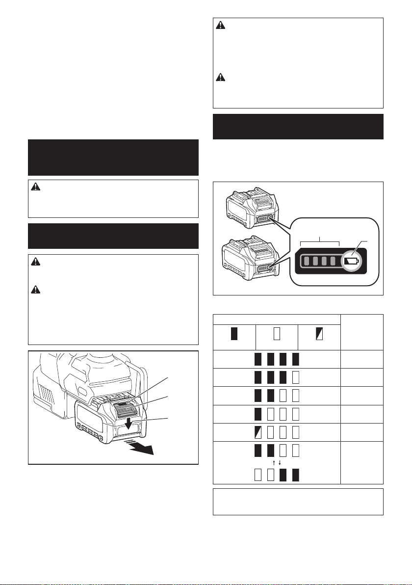
31 ESPAÑOL
26. No inserte ningún otro dispositivo que no sea
la unidad inalámbrica de Makita en la ranura de
la herramienta.
27. No utilice la herramienta si la tapa de la ranura
está dañada. La entrada de agua, polvo o sucie-
dad en la ranura podría causar una avería.
28. No jale ni tuerza la tapa de la ranura más de
lo necesario. Vuelva a colocar la tapa si ésta se
sale de la herramienta.
29. Reemplace la tapa de la ranura si llega a per-
derse o dañarse.
GUARDE ESTAS INSTRUCCIONES.
DESCRIPCIÓN DEL
FUNCIONAMIENTO
PRECAUCIÓN: Asegúrese siempre de que la
herramienta esté apagada y el cartucho de batería
haya sido extraído antes de realizar cualquier
ajuste o comprobación en la herramienta.
Instalación o extracción del
cartucho de batería
PRECAUCIÓN: Apague siempre la herra-
mienta antes de colocar o quitar el cartucho de
batería.
PRECAUCIÓN: Sujete la herramienta y el car-
tucho de la batería con rmeza al colocar o quitar
el cartucho de batería. Si no se sujeta con rmeza la
herramienta y el cartucho de batería, puede ocasio-
nar que se resbalen de sus manos causando daños
a la herramienta y al cartucho de batería, así como
lesiones a la persona.
1
2
3
► 1. Indicador rojo 2. Botón 3. Cartucho de batería
Para quitar el cartucho de batería, deslícelo de la herra-
mienta mientras desliza el botón sobre la parte delan-
tera del cartucho.
Para colocar el cartucho de batería, alinee la lengüeta
sobre el cartucho de batería con la ranura en la carcasa
y deslice en su lugar. Inserte por completo hasta que
se je en su lugar con un pequeño clic. Si puede ver el
indicador rojo del lado superior del botón, esto indica
que no ha quedado jo por completo.
PRECAUCIÓN: Introduzca siempre com-
pletamente el cartucho de batería hasta que
el indicador rojo no pueda verse. Si no, podría
accidentalmente salirse de la herramienta y caer al
suelo causando una lesión a usted o alguien a su
alrededor.
PRECAUCIÓN: No instale el cartucho de
batería a la fuerza. Si el cartucho no se desliza al
interior fácilmente, se debe a que no está siendo
insertado correctamente.
Indicación de la capacidad restante
de la batería
Oprima el botón de vericación en el cartucho de la
batería para que indique la capacidad restante de la
batería. Las luces indicadoras se iluminarán por algu-
nos segundos.
1
2
► 1. Luces indicadoras 2. Botón de vericación
Luces indicadoras Capacidad
restante
Iluminadas Apagadas Parpadeando
75% a 100%
50% a 75%
25% a 50%
0% a 25%
Cargar la
batería.
La batería
pudo haber
funcionado
mal.
NOTA: Dependiendo de las condiciones de uso y
la temperatura ambiente, la indicación podrá diferir
ligeramente de la capacidad real.
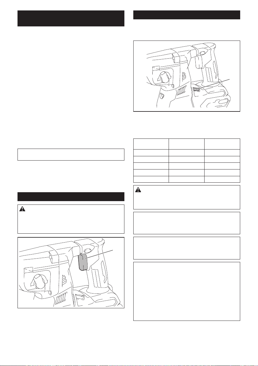
32 ESPAÑOL
Sistema de protección para la
herramienta/batería
La herramienta está equipada con un sistema de pro-
tección de la herramienta/batería. Este sistema corta
en forma automática el suministro de energía al motor
para prolongar la vida útil de la herramienta y la batería.
La herramienta se detendrá automáticamente durante
la operación si la herramienta o la batería se someten a
una de las siguientes condiciones:
Protección contra sobrecarga
Cuando la batería se esté utilizando de una manera
que cause que consuma una cantidad de corriente
anormalmente alta, la herramienta se detendrá automá-
ticamente sin indicación alguna. En este caso, apague
la herramienta y detenga la aplicación que causó que la
herramienta se sobrecargara. Luego encienda la herra-
mienta para reiniciarla.
Protección contra sobrecalentamiento
Cuando la herramienta o la batería se sobrecalienten,
la herramienta se detendrá automáticamente. En este
caso, permita que la herramienta y la batería se enfríen
antes de volver a encender la herramienta.
NOTA: Cuando la herramienta se sobrecaliente, la
lámpara parpadeará.
Protección en caso de sobredescarga
Cuando la capacidad de la batería no es suciente, la
herramienta se detiene automáticamente. En este caso,
retire la batería de la herramienta y cárguela.
Accionamiento del interruptor
ADVERTENCIA: Antes de insertar el car-
tucho de batería en la herramienta, compruebe
siempre y cerciórese de que el gatillo interruptor
se acciona debidamente y que vuelve a la posi-
ción “OFF” (apagado) cuando lo suelta.
1
► 1. Gatillo interruptor
Para arrancar la herramienta, simplemente jale el gatillo
interruptor. La velocidad de la herramienta aumenta
al incrementar la presión en el gatillo interruptor. Para
detenerla, suelte el gatillo interruptor.
Cambio de velocidad
Las revoluciones y golpes por minuto se pueden ajustar
girando el selector de ajuste. El selector está marcado
del 1 (velocidad más baja) al 5 (velocidad más alta).
1
► 1. Selector de ajuste
Consulte la tabla a continuación para ver la relación
entre el número en el selector de ajuste y las revolucio-
nes y golpes por minuto.
Número Revoluciones por
minuto
Golpes por minuto
5 980 5 000
4 870 4 440
3 630 3 210
2 380 1 940
1 300 1 530
PRECAUCIÓN: No gire el selector de ajuste
cuando la herramienta esté funcionando. De lo
contrario, podría resultar en la pérdida de control
de la herramienta y ocasionar una lesión.
AVISO: Si la herramienta es operada a baja velo-
cidad de forma continua durante un tiempo pro-
longado, el motor se sobrecargará provocando
que la herramienta se averíe.
AVISO: El selector de ajuste de velocidad solo
puede girarse hasta 5 y de regreso a 1. No lo
fuerce más allá de 5 o 1 o la función de ajuste de
velocidad podría dejar de funcionar.
NOTA: Función de rotación suave sin carga
Cuando el selector de ajuste de velocidad está ajus-
tado en “4” o más, la herramienta automáticamente
reduce la velocidad a velocidad sin carga a n de
disminuir la vibración en esta modalidad. Cuando la
operación comienza con una punta contra concreto,
los golpes por minuto se incrementan y alcanzan
los números que se muestran en la tabla. Cuando la
temperatura es baja y hay menos uidez de grasa, la
herramienta podría no tener esta función aun con el
motor girando.
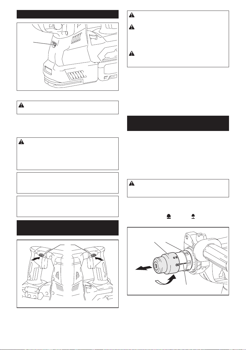
33 ESPAÑOL
Iluminación de la luz delantera
1
► 1. Luz
PRECAUCIÓN: No mire a la luz ni vea a la
fuente de luz directamente.
Jale el gatillo interruptor para encender la luz. La luz
continúa iluminándose mientras se está jalando el
gatillo interruptor. La luz se apaga aproximadamente 10
segundos tras haber liberado el gatillo interruptor.
PRECAUCIÓN: Si la lámpara se apaga des-
pués de parpadear durante algunos segundos,
la tecnología de detección de retroalimentación
activa no está funcionando correctamente.
Solicite la reparación al centro de servicio Makita
de su localidad.
NOTA: Utilice un paño seco para quitar la suciedad
de la lente de la lámpara. Tenga cuidado de no rayar
la lente de la lámpara ya que la iluminación podría
disminuir.
NOTA: Cuando el sistema de recolección de polvo se
encuentre instalado en la herramienta, la lámpara del
sistema de recolección de polvo se encenderá en vez
de la lámpara de la herramienta.
Accionamiento del conmutador de
inversión de giro
1
AB
► 1. Palanca del interruptor de inversión
PRECAUCIÓN: Conrme siempre la direc-
ción de rotación antes de la operación.
PRECAUCIÓN: Utilice el conmutador de
inversión solamente después de que la herra-
mienta haya parado completamente. Si cambia
la dirección de rotación antes de que la herramienta
haya parado podría dañarla.
PRECAUCIÓN: Cuando no esté utilizando la
herramienta, ponga siempre la palanca del con-
mutador de inversión en la posición neutral.
Esta herramienta tiene un conmutador de inversión
para cambiar la dirección de rotación. Presione la
palanca del conmutador de inversión desde el lado A
para una rotación en sentido de las manecillas del reloj
o desde el lado B, para una rotación en sentido inverso
al de las manecillas del reloj.
Cuando la palanca del conmutador de inversión esté
en la posición neutral, no se podrá jalar el gatillo
conmutador.
Cambio del portabrocas de cambio
rápido para SDS-plus
Para el modelo GRH02
El portabrocas de cambio rápido para SDS-plus puede
intercambiarse fácilmente por el portabrocas adaptador
de cambio rápido.
Extracción del portabrocas de
cambio rápido para SDS-plus
PRECAUCIÓN: Antes de extraer el portabro-
cas de cambio rápido para SDS-plus, asegúrese de
retirar la punta.
Sujete la cubierta de cambio del portabrocas de cam-
bio rápido para SDS-plus y gírela en la dirección de la
echa hasta que la línea de la cubierta de cambio se
desplace del símbolo
al símbolo . Jale con fuerza
en la dirección de la echa.
1 2
3
► 1. Portabrocas de cambio rápido para SDS-plus
2. Cubierta de cambio 3. Línea de la cubierta de
cambio
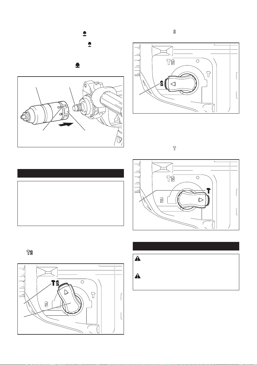
34 ESPAÑOL
Instalación del portabrocas
adaptador de cambio rápido
Verique que la línea del portabrocas adaptador de
cambio rápido muestre el símbolo
. Sujete la cubierta
de cambio del portabrocas adaptador de cambio
rápido y ajuste la línea en el símbolo
. Coloque el
portabrocas adaptador de cambio rápido en el eje de
la herramienta. Sujete la cubierta de cambio del porta-
brocas adaptador de cambio rápido y gire la línea de la
cubierta de cambio al símbolo
hasta que se pueda
escuchar claramente un clic.
1 2
3 4
► 1. Portabrocas adaptador de cambio rápido 2. Eje
3. Línea de la cubierta de cambio 4. Cubierta de
cambio
Selección del modo de accionamiento
AVISO: No gire la perilla de cambio de modo de
accionamiento cuando la herramienta esté en
marcha. Esto podría causar daños a la herramienta.
AVISO: Para evitar un desgaste rápido del meca-
nismo de cambio de modo, asegúrese siempre
de que la perilla de cambio de modo de acciona-
miento se encuentre realmente ubicada en una de
las tres posiciones del modo de accionamiento.
Rotación con percusión
Para taladrar en concreto, mampostería, etc., gire la
perilla de cambio de modo de accionamiento al sím-
bolo
. Utilice una broca con punta de carburo de
tungsteno (accesorio opcional).
1
2
► 1. Rotación con percusión 2. Perilla de cambio de
modo de accionamiento
Sólo rotación
Para taladrar en materiales de madera, metal o
plástico, gire la perilla de cambio de modo de accio-
namiento al símbolo
. Utilice una broca helicoidal o
broca para madera.
1
► 1. Sólo rotación
Sólo percusión
Para operaciones de cincelado, desincrustación o
demolición, gire la perilla de cambio de modo de accio-
namiento al símbolo
. Utilice un cincel de punta,
cincel plano, cincel de desincrustación, etc.
1
► 1. Sólo percusión
Gancho
PRECAUCIÓN: Extraiga siempre la bate-
ría cuando vaya a colgar la herramienta con el
gancho.
PRECAUCIÓN: Nunca enganche la herra-
mienta en un lugar elevado o en una supercie
potencialmente inestable.
El gancho resulta conveniente para colgar temporal-
mente la herramienta.
Cuando vaya a utilizar el gancho, simplemente leván-
telo hasta que quede trabado en la posición abierta.
Cuando no lo vaya a utilizar, siempre bájelo hasta que
quede trabado en la posición cerrada.
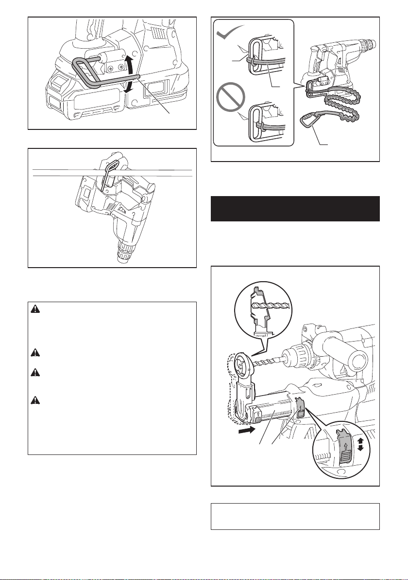
35 ESPAÑOL
1
► 1. Gancho
Conexión del cordel de seguridad
(correa de amarre) al gancho
PRECAUCIÓN: No utilice un gancho y tor-
nillos que ya estén dañados. Antes de usarlos,
verique la existencia de daños, roturas o defor-
maciones y asegúrese de que los tornillos estén
apretados.
PRECAUCIÓN: Asegúrese de que el gancho
esté instalado rmemente con los tornillos.
PRECAUCIÓN: No extraiga el cartucho de la
batería mientras cuelga la herramienta. La herra-
mienta podría caer si los tornillos no están apretados.
PRECAUCIÓN: Utilice siempre una carabina
de bloqueo (de tipo multiacción y de seguro de
rosca) y asegúrese de sujetar el cordel de segu-
ridad (correa de amarre) a la parte de doble bucle
del gancho. Una sujeción inapropiada ocasionaría
que la herramienta se cayera del gancho y resultar en
lesiones personales.
El gancho también se utiliza para conectar el cordel de
seguridad (correa de amarre). Asegúrese de conectar
el cordón de seguridad (correa de amarre) a la parte de
doble bucle del gancho.
1
2
3
► 1. Parte de doble bucle del gancho 2. Cordel de
seguridad (correa de amarre) 3. Carabina de blo-
queo (de tipo multiacción y de seguro de rosca)
Ajuste de la posición de la boquilla
del sistema de recolección de polvo
Accesorio opcional
Empuje hacia adentro la guía mientras oprime hacia
arriba el botón de ajuste de la guía y luego suelte el
botón en la posición deseada.
1 2
► 1. Guía 2. Botón de ajuste de la guía
NOTA: Antes de ajustar la posición de la boquilla,
libere totalmente la boquilla hacia adelante opri-
miendo hacia arriba el botón de ajuste de la guía.
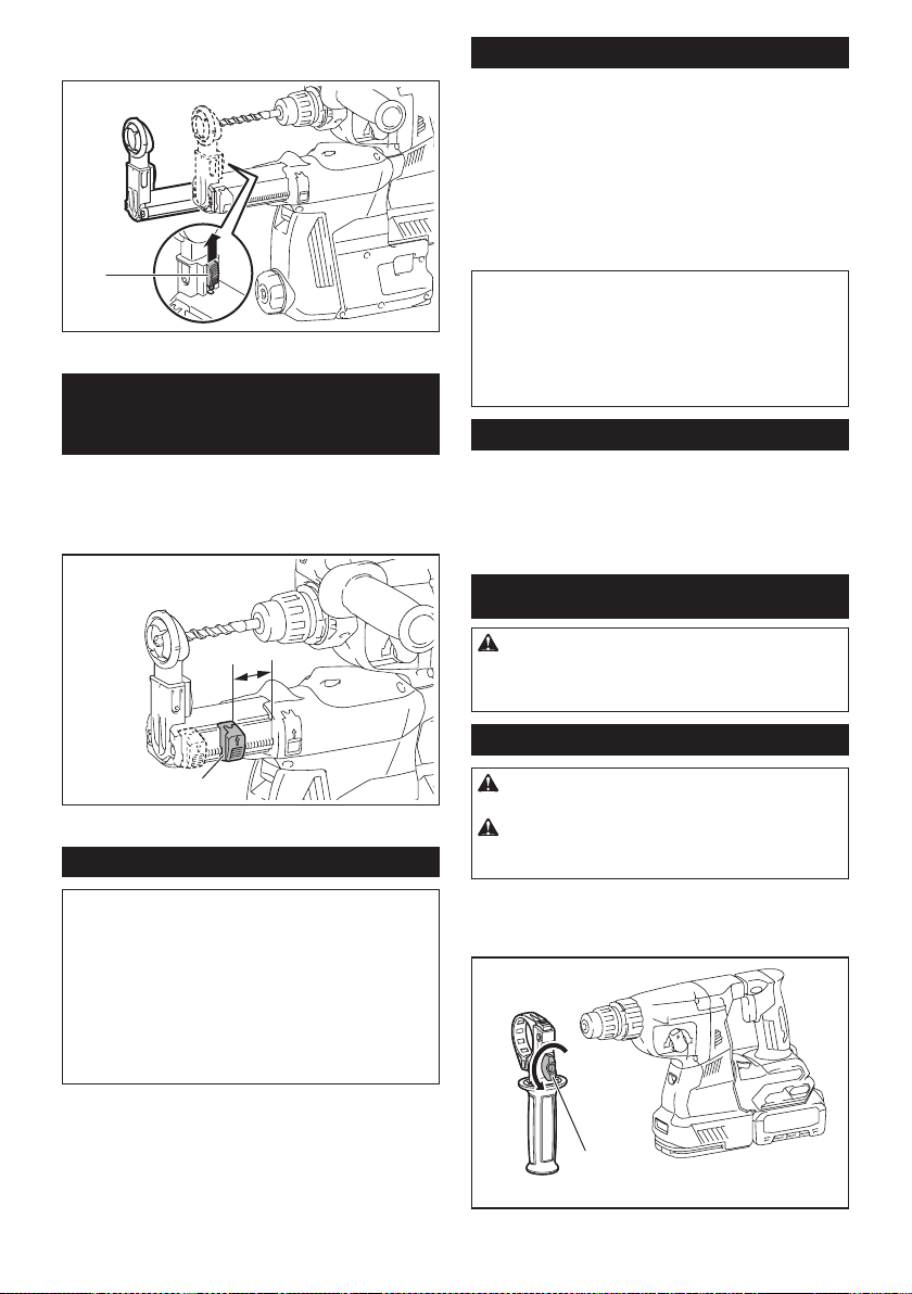
36 ESPAÑOL
Si va a instalar una broca larga, extienda la guía opri-
miendo hacia arriba el botón de extensión.
1
► 1. Botón de extensión
Ajuste de la profundidad de
perforación del sistema de
recolección de polvo
Accesorio opcional
Deslice el botón de ajuste de profundidad hasta la
posición deseada mientras lo oprime hacia arriba. La
distancia (A) es la profundidad de perforación.
1
A
► 1. Botón de ajuste de profundidad
Limitador de torsión
AVISO: En cuanto el limitador de torsión se
accione, apague de inmediato la herramienta.
Esto ayudará a evitar el desgaste prematuro de la
herramienta.
AVISO: Las brocas tales como las de sierra
perforadora, las cuales tienden a atorarse o
engancharse fácilmente en el agujero, no son
adecuadas para esta herramienta. Esto es debido
a que pueden provocar que el limitador de torsión se
accione con demasiada frecuencia.
El limitador de torsión se accionará una vez que se
alcance un cierto nivel de torsión. El motor se desen-
ganchará del eje de salida. Cuando esto suceda, la
broca dejará de girar.
Funcionamiento electrónico
La herramienta está equipada con funciones electróni-
cas para facilitar la operación.
• Control de velocidad constante
La función de control de velocidad permite una
rotación constante independientemente de las
condiciones de carga.
•
Tecnología de detección de retroalimentación activa
Si la herramienta gira a la aceleración predetermi-
nada durante la operación, el motor será detenido
forzadamente para reducir la carga en la muñeca.
NOTA: Esta función no servirá si la aceleración no
alcanza la predeterminada al girar la herramienta.
NOTA: Si la punta gira a la aceleración predetermi-
nada durante el cincelado, la desincrustación o la
demolición, el motor será detenido forzadamente. En
este caso, suelte el gatillo interruptor y luego jálelo
para reiniciar la herramienta.
Freno eléctrico
La herramienta está equipada con un freno eléctrico. Si
la herramienta falla constantemente en detenerse tras
soltar el gatillo interruptor, lleve la herramienta a mante-
nimiento a un centro de servicio Makita.
MONTAJE
PRECAUCIÓN: Asegúrese siempre de que la
herramienta esté apagada y el cartucho de batería
haya sido extraído antes de realizar cualquier
trabajo en la misma.
Empuñadura lateral (mango auxiliar)
PRECAUCIÓN: Utilice siempre la empuña-
dura lateral para garantizar una operación segura.
PRECAUCIÓN: Después de instalar o ajustar
la empuñadura lateral, asegúrese de que quede
rmemente asegurada.
Para instalar la empuñadura lateral, siga los pasos a
continuación.
1.
Aoje el tornillo de mariposa en la empuñadura lateral.
1
► 1. Tornillo de mariposa
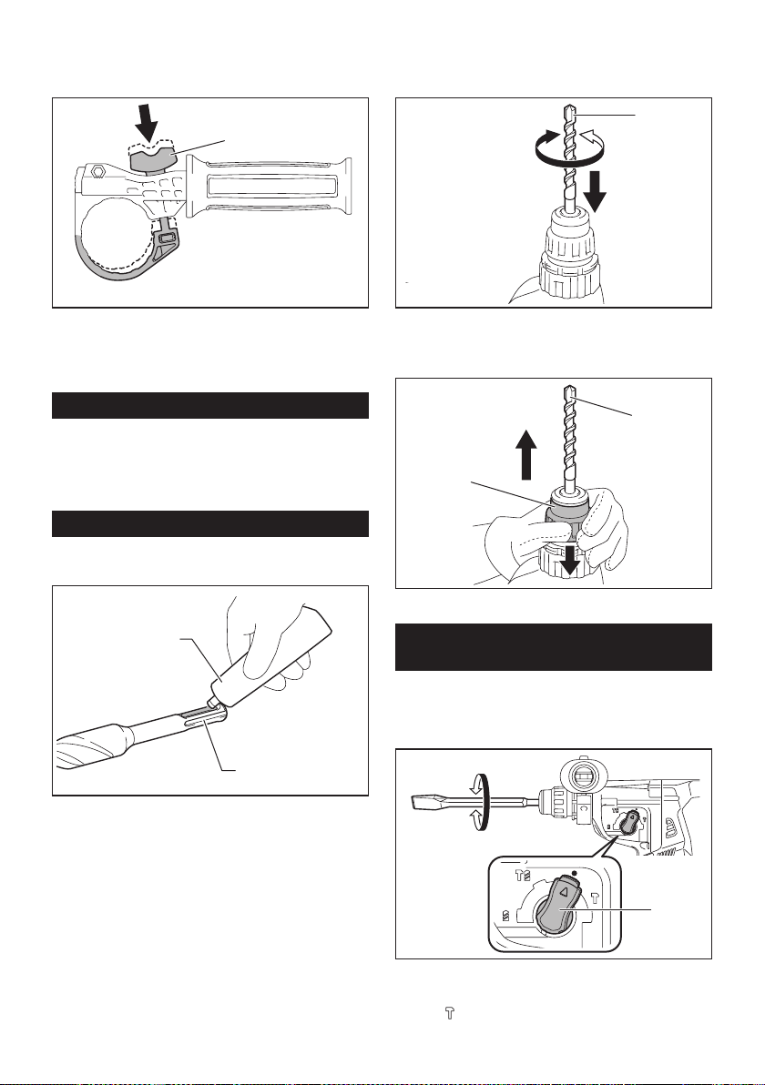
37 ESPAÑOL
2. Instale la empuñadura lateral mientras presiona
el tornillo de mariposa de modo que las ranuras en la
empuñadura encajen en las protuberancias del cilindro
de la herramienta.
1
► 1. Tornillo de mariposa
3. Apriete el tornillo de mariposa para asegurar
la empuñadura. La empuñadura puede jarse en el
ángulo deseado.
Grasa
Aplique previamente una pequeña cantidad de grasa
(alrededor de 0,5 g - 1 g) en el extremo de la espiga de
la broca.
La lubricación del portabrocas asegura un acciona-
miento suave y una vida útil más larga.
Instalación o extracción de la broca
Limpie el extremo de la espiga de la broca y aplique
grasa antes de instalar la broca.
1
2
► 1. Extremo de la espiga 2. Grasa
Inserte la broca en la herramienta. Gire la broca y
empújela hacia adentro hasta que quede enganchada.
Después de instalar la broca, asegúrese siempre de que la broca
quede asegurada en su lugar intentando jalarla hacia afuera.
1
► 1. Broca
Para extraer la broca, jale hasta abajo la cubierta del
portabrocas y jale la broca hacia afuera.
1
2
► 1. Broca 2. Cubierta del portabrocas
Ángulo del cincel (durante el cincelado,
desincrustación o demolición)
El cincel puede jarse en el ángulo deseado. Para
cambiar el ángulo del cincel, gire la perilla de cambio de
modo de accionamiento al símbolo O. Gire el cincel al
ángulo deseado.
1
► 1. Perilla de cambio de modo de accionamiento
Gire la perilla de cambio de modo de accionamiento al
símbolo
. Luego asegúrese de que el cincel quede
asegurado en su lugar girándolo ligeramente.
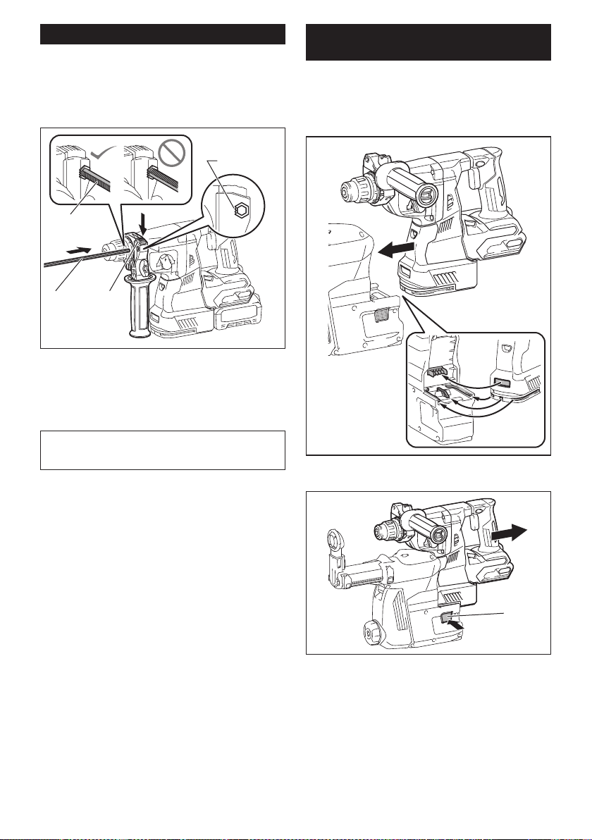
38 ESPAÑOL
Calibrador de profundidad
El calibrador de profundidad sirve para perforar oricios
de profundidad uniforme.
Oprima y mantenga oprimido el botón de bloqueo y
luego inserte el calibrador de profundidad en el oricio
hexagonal. Asegúrese de que el lado dentado del cali-
brador de profundidad quede de frente a la marca.
3
4
1 2
► 1. Calibrador de profundidad 2. Botón de bloqueo
3. Marca 4. Lado dentado
Ajuste el calibrador de profundidad moviéndolo hacia
atrás y hacia adelante mientras oprime el botón de blo-
queo. Después de ajustarlo, suelte el botón de bloqueo
para bloquear el calibrador de profundidad.
NOTA: Asegúrese de que el calibrador de profundi-
dad no toque el cuerpo principal de la herramienta al
momento de jarlo.
Instalación o extracción del sistema
de recolección de polvo
Accesorio opcional
Para instalar el sistema de recolección de polvo, inserte
la herramienta en el sistema de recolección de polvo
hasta que llegue al fondo y quede asegurado en su
lugar con un pequeño doble clic.
Para extraer el sistema de recolección de polvo, jale la
herramienta mientras oprime el botón de desbloqueo.
1
► 1. Botón de desbloqueo
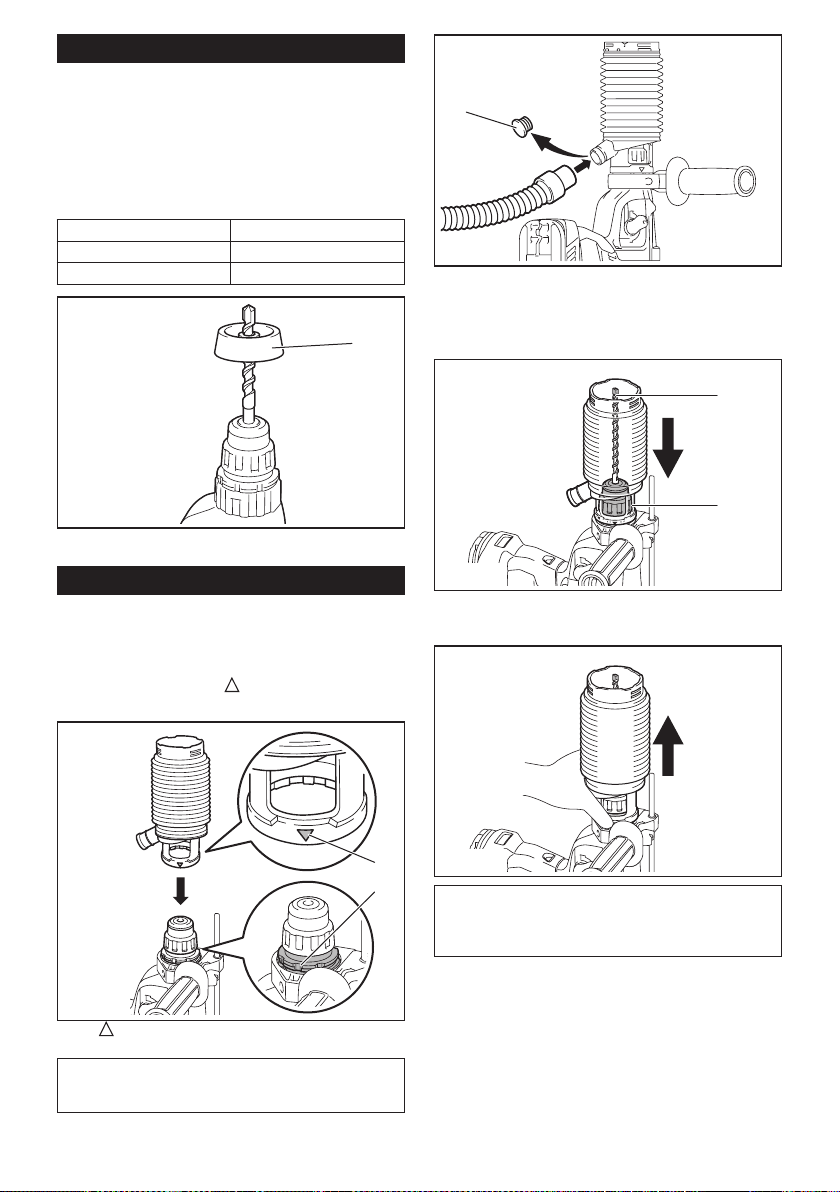
39 ESPAÑOL
Contenedor de polvo
Accesorio opcional
Utilice el contenedor de polvo para evitar que el polvo
caiga sobre la herramienta y sobre usted al realizar
operaciones de perforación por encima de su cabeza.
Fije el contenedor de polvo en la punta tal como se
muestra en la ilustración. El tamaño de las puntas en
las que el contenedor de polvo puede jarse es el que
se indica a continuación.
Modelo Diámetro de la punta
Contenedor de polvo 5 6 mm (1/4″) - 14,5 mm (9/16″)
Contenedor de polvo 9 12 mm (15/32″) - 16 mm (5/8″)
1
► 1. Contenedor de polvo
Juego contenedor de polvo
Accesorio opcional
Antes de instalar el juego contenedor de polvo, extraiga
la punta de la herramienta en caso de estar instalada.
Instale el juego contenedor de polvo en la herramienta
de manera que el símbolo
en el contenedor de
polvo quede alineado con la ranura en la herramienta.
2
1
► 1. símbolo 2. Ranura
NOTA: Si conecta una aspiradora al juego contene-
dor de polvo, retire la tapa guardapolvos antes de
conectarla.
1
► 1. Tapa guardapolvos
Para extraer el juego contenedor de polvo, retire la
punta mientras jala la cubierta del portabrocas en la
dirección de la echa.
1
2
► 1. Punta 2. Cubierta del portabrocas
Tome el contenedor de polvo desde la raíz y sáquelo.
NOTA: Si la tapa llega a salirse del contenedor de
polvo, fíjela con su lado impreso orientado hacia
arriba de manera que la ranura en la tapa encaje en
la periferia interior del accesorio.
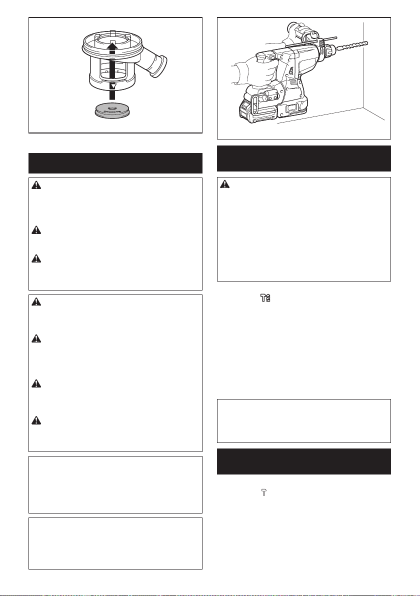
40 ESPAÑOL
OPERACIÓN
PRECAUCIÓN: Utilice siempre la empuña-
dura lateral (mango auxiliar) y sujete rmemente
la herramienta tanto de la empuñadura lateral
como del mango del interruptor durante las
operaciones.
PRECAUCIÓN: Asegúrese siempre de que
la pieza de trabajo quede asegurada antes de la
operación.
PRECAUCIÓN: No jale hacia afuera la herra-
mienta con demasiada fuerza aun si la punta
se atora. La pérdida de control podría causar
lesiones.
PRECAUCIÓN: El sistema de recolección de
polvo está diseñado para perforar en concreto
únicamente. No utilice el sistema de recolección
de polvo para perforar en metal ni en madera.
PRECAUCIÓN: Cuando vaya a utilizar la
herramienta con el sistema de recolección de
polvo, asegúrese de colocar el ltro en el sistema
de recolección de polvo para evitar la inhalación
de polvo.
PRECAUCIÓN: Antes de utilizar el sistema
de recolección de polvo, verique que el ltro no
esté dañado. El no hacerlo podría causar la inhala-
ción de polvo.
PRECAUCIÓN: El sistema de recolección
de polvo recolecta el polvo que se genera en un
volumen considerable, sin embargo, es imposible
recolectarlo todo.
AVISO: No utilice el sistema de recolección de
polvo para taladrado con corona ni cincelado.
AVISO: No utilice el sistema de recolección de
polvo para perforar en concreto húmedo ni lo
utilice en entornos mojados. El hacerlo podría
causar averías.
NOTA: Si el cartucho de batería se encuentra a baja
temperatura, la herramienta podría no alcanzar su
máxima capacidad. En este caso, caliente el cartucho
de batería usando la herramienta sin carga durante
un rato a n de lograr que la herramienta alcance su
máxima capacidad.
Operación de taladrado con
percusión
PRECAUCIÓN: En el momento de comenzar
a penetrar, cuando se obstruye el oricio con viru-
tas y partículas, o cuando se topa contra varillas
de refuerzo de concreto, se ejerce una tremenda y
repentina fuerza de torsión sobre la herramienta/
broca. Utilice siempre la empuñadura lateral
(mango auxiliar) y sujete rmemente la herra-
mienta tanto de la empuñadura lateral como del
mango del interruptor durante las operaciones. El
no hacerlo puede provocar la pérdida de control de
la herramienta y potencialmente ocasionar lesiones
graves.
Ajuste la perilla de cambio de modo de accionamiento
en el símbolo
.
Coloque la broca donde desee hacer el agujero y luego
jale el gatillo interruptor. No fuerce la herramienta. Los
mejores resultados se obtienen con una ligera presión.
Mantenga la herramienta en posición y evite que se
deslice y se salga del agujero.
No aplique más presión cuando el agujero se obstruya
con astillas o partículas. En vez de esto, haga funcionar
la herramienta sin presión y luego retire parcialmente
la broca del agujero. Repitiendo esto varias veces, el
agujero se limpiará y se podrá reanudar el taladrado de
manera normal.
NOTA: Es posible que se produzca excentricidad en
la rotación de la broca al operar la herramienta sin
carga. La herramienta se centrará automáticamente
durante la operación. Esto no afectará la precisión en
el taladrado.
Cincelado/desincrustación/
demolición
Ajuste la perilla de cambio de modo de accionamiento
en el símbolo
.
Sujete la herramienta rmemente con ambas manos.
Encienda la herramienta y aplique una ligera presión
sobre ella de manera que no rebote de forma descon-
trolada.
Aplicar mucha presión sobre la herramienta no incre-
mentará la eciencia.
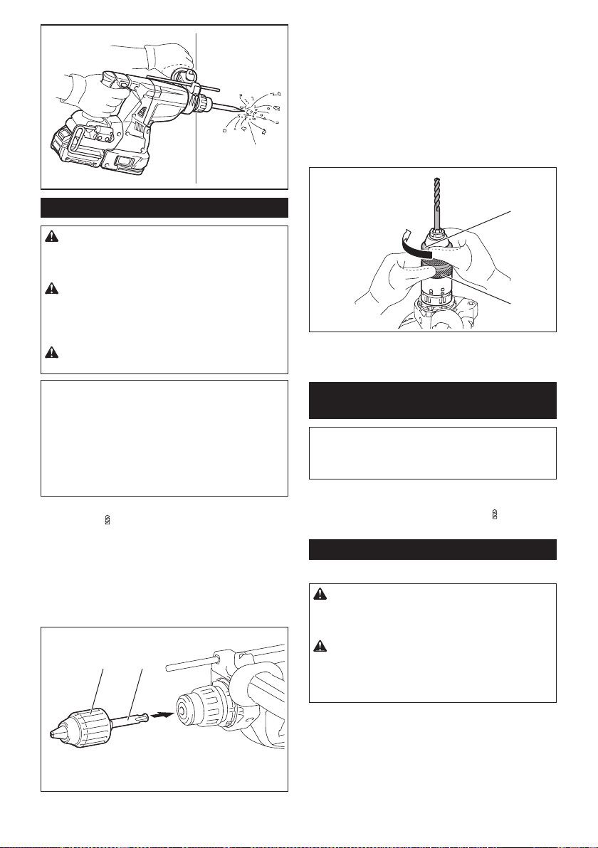
41 ESPAÑOL
Taladrado en madera o metal
PRECAUCIÓN:
Sujete rmemente la herramienta y
tenga cuidado cuando la broca de taladro comience a pene-
trar en la pieza de trabajo. La fuerza ejercida en la herramienta/
broca de taladro al momento de la penetración es enorme.
PRECAUCIÓN:
Para extraer una broca de tala-
dro atorada, basta simplemente con ajustar el inte-
rruptor de inversión en rotación inversa para hacerla
retroceder. Sin embargo, la herramienta puede retro-
ceder bruscamente si no la sujeta con rmeza.
PRECAUCIÓN:
Asegure siempre las piezas de tra-
bajo con un tornillo de banco o dispositivo de sujeción similar.
AVISO:
Nunca use la “rotación con percusión” cuando
el portabrocas adaptador esté instalado en la herra-
mienta. Esto podría causar daños al portabrocas adaptador.
Asimismo, el portabrocas adaptador podría salirse al
invertir la rotación de la herramienta.
AVISO:
Ejercer una presión excesiva sobre la herramienta
no hará que consiga taladrar más rápido. De hecho, una pre-
sión excesiva sólo logrará dañar la punta de la broca de taladro,
reducir el desempeño y acortar la vida útil de la herramienta.
Ajuste la perilla de cambio de modo de accionamiento
en el símbolo
.
Para el modelo GRH01
Accesorio opcional
Fije el adaptador de mandril en un portabrocas adaptador sin
llave en el que pueda instalarse un tornillo que mida 1/2″-20,
y después instálelos en la herramienta. Cuando lo instale,
consulte la sección “Instalación o extracción de la broca”.
1 2
►
1. Portabrocas adaptador sin llave 2. Adaptador de mandril
Para el modelo GRH02
Utilice el portabrocas adaptador de cambio rápido como
equipo estándar. Cuando lo instale, consulte la sec-
ción “Cambio del portabrocas de cambio rápido para
SDS-plus”.
Sostenga el anillo y gire el mandril en sentido inverso
al de las manecillas del reloj para abrir las mordazas
del portabrocas. Coloque la punta en el mandril hasta
que llegue al tope. Sostenga el anillo rmemente y gire
el mandril en el sentido de las manecillas del reloj para
apretar el portabrocas.
1
2
► 1. Mandril 2. Anillo
Para extraer la punta, sostenga el anillo y gire el man-
dril en sentido inverso al de las manecillas del reloj.
Taladrado con punta de corona de
diamante
AVISO: Si realiza operaciones de taladrado con
punta de corona de diamante usando la acción de
“rotación con percusión”, la punta de corona de
diamante podría dañarse.
Cuando realice operaciones de taladrado con punta de
corona de diamante, ajuste siempre la perilla de cambio
de modo de accionamiento a la posición
para utilizar
la acción “sólo rotación”.
Sacudir el polvo del ltro
Accesorio opcional
PRECAUCIÓN: No gire el selector de la caja
para polvo mientras la caja para polvo se extrae
del sistema de recolección de polvo. De lo contra-
rio puede ocasionarse la inhalación de polvo.
PRECAUCIÓN: Apague siempre la herra-
mienta antes de girar el selector de la caja para
polvo. Si se gira el selector mientras la herramienta
está en funcionamiento, se puede ocasionar la pér-
dida del control de la herramienta.
Si se sacude el polvo del ltro en el interior de la caja
para polvo, se puede mantener la eciencia de aspira-
ción y reducir además el número de veces que hay que
desechar el polvo.
Gire tres veces el selector de la caja para polvo cada
vez que se acumulen 50 000 mm
3
de polvo o cuando
crea que el rendimiento de aspiración se ha reducido.
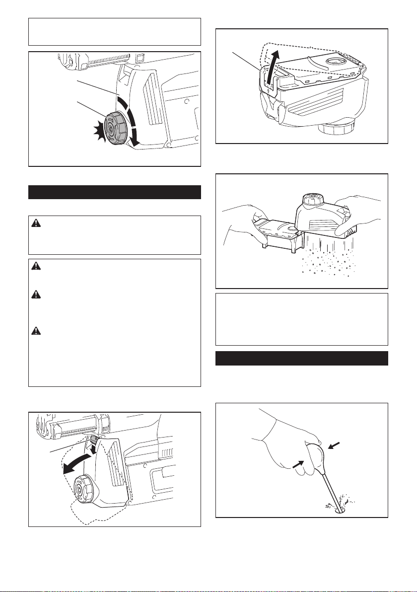
42 ESPAÑOL
NOTA: 50 000 mm
3
de polvo equivalen a perforar
10 oricios de ø10 mm y 65 mm de profundidad (14
oricios de ø3/8″ y 2″ de profundidad).
2
1
► 1. Caja para polvo 2. Selector
Eliminación del polvo
Accesorio opcional
PRECAUCIÓN: Asegúrese siempre de que la
herramienta esté apagada y el cartucho de batería
haya sido extraído antes de realizar cualquier
trabajo en la misma.
PRECAUCIÓN: Cuando vaya a proceder a
eliminar el polvo, asegúrese de usar una máscara
contra polvo.
PRECAUCIÓN: Vacíe la caja para polvo regu-
larmente antes de que ésta se llene. El no hacerlo
podría reducir el desempeño de la recolección de
polvo y causar la inhalación de polvo.
PRECAUCIÓN: El desempeño de la recolec-
ción de polvo se verá reducido si el ltro en la
caja para polvo llega a obstruirse. Como referen-
cia, reemplace el ltro con uno nuevo después de
aproximadamente 200 veces que la caja se haya
llenado de polvo. El no hacerlo podría causar la
inhalación de polvo.
1. Extraiga la caja para polvo mientras presiona
hacia abajo la palanca de la caja para polvo.
1
► 1. Palanca
2. Abra la cubierta de la caja para polvo.
1
► 1. Cubierta
3. Elimine el polvo y luego limpie el ltro.
AVISO: Cuando limpie el ltro, golpee suave-
mente la caja del ltro con la mano para eliminar
el polvo. No golpee el ltro directamente; evite
tocarlo con un cepillo u objeto similar, ni sople
aire comprimido al ltro. El hacerlo podría dañar
el ltro.
Soplador
Accesorio opcional
Después de perforar el agujero, utilice el soplador para
limpiar el polvo del agujero.
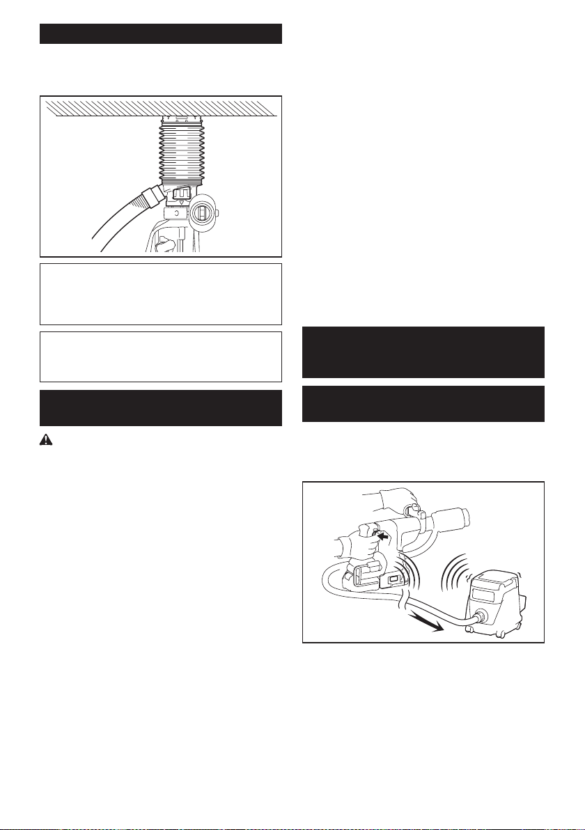
43 ESPAÑOL
Uso del juego contenedor de polvo
Accesorio opcional
Fije el juego contenedor de polvo contra el techo
cuando opere la herramienta.
AVISO: No utilice el juego contenedor de polvo
cuando perfore en metal o un material similar.
Esto podría dañar el juego contenedor de polvo
debido al calor producido por las pequeñas partí-
culas de polvo de metal o material similar.
AVISO: No instale ni extraiga el juego contene-
dor de polvo con la broca instalada en la herra-
mienta. Esto podría dañar el juego contenedor de
polvo y causar la ltración de polvo.
Conexión del cordel de seguridad
(correa de amarre) al gancho
Advertencias de seguridad especícas para uso
en alturas
Lea todas las advertencias de seguridad e instruc-
ciones. El no seguir las advertencias e instrucciones
podría ocasionar lesiones graves.
1. Mantenga siempre la herramienta atada
cuando trabaje “en alturas”. La longitud
máxima del cordel es de 2 m (6,5 ft).
La altura de caída máxima permisible para
el cordel de seguridad (correa de amarre) no
deberá superar los 2 m (6,5 ft).
2. Use solo con cordeles apropiados para este
tipo de herramienta y con una capacidad nomi-
nal de al menos 8,0 kg (17,6 lbs).
3.
No ancle el cordel de la herramienta a nada en su
cuerpo o a componentes móviles. Ancle el cordel
de la herramienta a una estructura rígida que pueda
soportar las fuerzas de una herramienta en caída.
4. Asegúrese de que el cordel esté debidamente
asegurado de cada extremo previo al uso.
5. Inspeccione la herramienta y el cordel antes
de cada uso para ver que no tengan daños y
que funcionen correctamente (incluyendo la
tela y las puntadas). No los utilice si presentan
daños o no funcionan correctamente.
6.
No envuelva cordeles alrededor de bordes losos o áspe-
ros ni permita que estos entren en contacto con ellos.
7. Asegure el otro extremo del cordel fuera del
área de trabajo de manera que la herramienta
en caída esté rmemente sujetada.
8.
Fije el cordel de forma que la herramienta se mueva
lejos del operador en caso de que esta se caiga. Las
herramientas en caída se balancean en el cordel, lo que
puede ocasionar lesiones o la pérdida del equilibrio.
9. No la utilice cerca de piezas móviles o maqui-
naria funcionando. El hacerlo podría ocasionar
riesgo de choque o enredo.
10. No transporte la herramienta sujetándola del
dispositivo de atadura o el cordel.
11. Cargue la herramienta únicamente entre sus
manos mientras mantenga bien el equilibrio.
12.
No sujete cordeles de seguridad a la herramienta de
manera que evite que los interruptores o el bloqueo para
el gatillo (de ser suministrado) funcionen correctamente.
13. Evite enredarse en el cordel.
14. Mantenga el cordel de seguridad alejado del
área de perforación de la herramienta.
15. Use una carabina de bloqueo (de tipo multiac-
ción y de seguro de rosca). No use carabinas
de tipo acción única con gancho de resorte.
16.
En caso de que la herramienta llegue a caerse, esta debe
etiquetarse, sacarse de servicio y ser inspeccionada por
una fábrica o centro de servicio autorizado Makita.
FUNCIÓN DE ACTIVACIÓN
INALÁMBRICA
Lo que puede hacer con la función
de activación inalámbrica
La función de activación inalámbrica permite una operación
limpia y cómoda. Si conecta a la herramienta una aspira-
dora compatible, podrá hacer que ésta funcione automáti-
camente al activar el interruptor de la herramienta.
Para hacer uso de la función de activación inalámbrica,
tenga preparado lo siguiente:
• Una unidad inalámbrica (accesorios opcionales)
• Una aspiradora compatible con la función de
activación inalámbrica
A continuación se presenta la descripción general del
ajuste de la función de activación inalámbrica. Consulte
cada sección para ver los procedimientos a detalle.
1. Instalación de la unidad inalámbrica
2. Registro de la herramienta para la aspiradora
3. Inicio de la función de activación inalámbrica
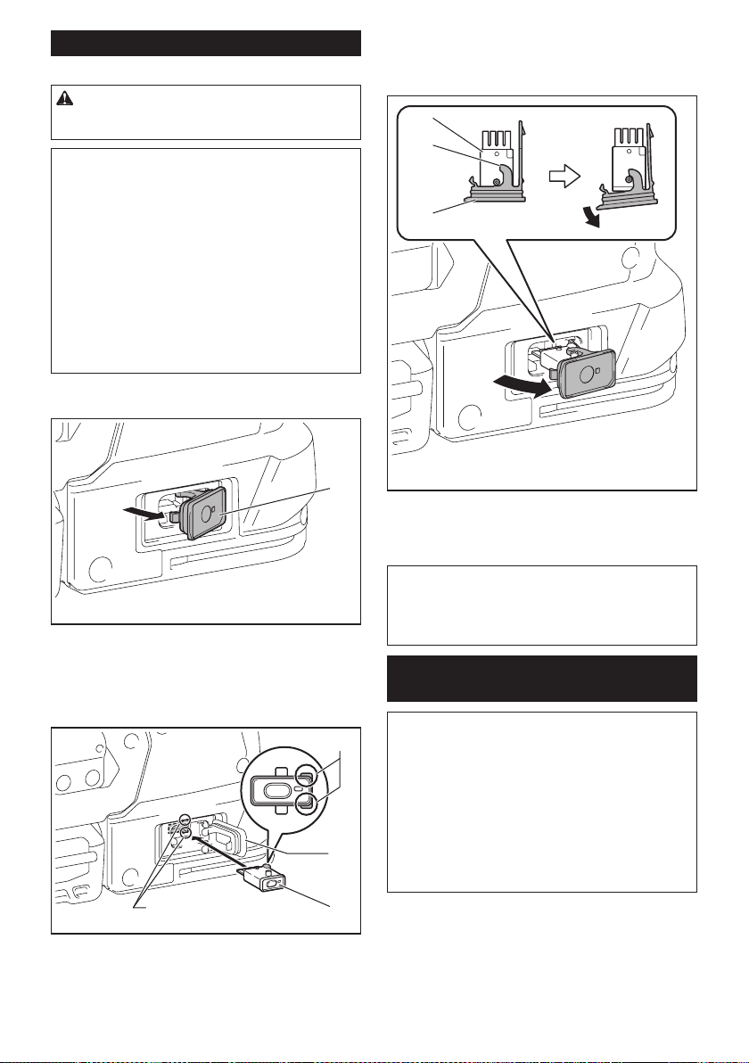
44 ESPAÑOL
Instalación de la unidad inalámbrica
Accesorio opcional
PRECAUCIÓN: Coloque la herramienta sobre
una supercie plana y estable cuando vaya a
instalar la unidad inalámbrica.
AVISO: Limpie el polvo y la suciedad en la herra-
mienta antes de instalar la unidad inalámbrica.
El polvo o la suciedad podrían causar una avería
si llegan a introducirse en la ranura de la unidad
inalámbrica.
AVISO: Para evitar una avería a causa de la elec-
tricidad estática, toque un material de descarga
de electricidad estática, tal como una pieza metá-
lica de la herramienta antes de levantar la unidad
inalámbrica.
AVISO: Cuando vaya a instalar la unidad inalám-
brica, asegúrese siempre de que ésta sea inser-
tada en la dirección correcta y que la tapa esté
completamente cerrada.
1. Abra la tapa en la herramienta tal como se mues-
tra en la ilustración.
1
► 1. Tapa
2. Inserte la unidad inalámbrica en la ranura y luego
cierre la tapa.
Cuando inserte la unidad inalámbrica, alinee las partes
salientes con las partes cóncavas en la ranura.
3
1
4
2
► 1. Unidad inalámbrica 2. Parte saliente 3. Tapa
4. Parte cóncava
Cuando extraiga la unidad inalámbrica, abra la tapa
lentamente. Los ganchos en la parte posterior de la
tapa levantarán la unidad inalámbrica mientras usted
jala hacia arriba la tapa.
1
2
3
► 1. Unidad inalámbrica 2. Gancho 3. Tapa
Una vez extraída la unidad inalámbrica, guárdela en el
estuche suministrado o en un contenedor libre de elec-
tricidad estática.
AVISO: Use siempre los ganchos en la parte
posterior de la tapa cuando extraiga la unidad
inalámbrica. Si los ganchos no sujetan la unidad
inalámbrica, cierre la tapa por completo y vuelva a
abrirla lentamente.
Registro de la herramienta para la
aspiradora
NOTA: Para el registro de la herramienta, se requiere
una aspiradora Makita compatible con la función de
activación inalámbrica.
NOTA: Termine de instalar la unidad inalámbrica en
la herramienta antes de comenzar con el registro de
la herramienta.
NOTA: Durante el registro de la herramienta, no jale
el gatillo interruptor ni active el interruptor de encen-
dido en la aspiradora.
NOTA: Consulte también el manual de instrucciones
de la aspiradora.
Si desea activar la aspiradora junto con el interruptor
de la herramienta, termine antes con el registro de la
herramienta.
1. Instale las baterías en la aspiradora y en la
herramienta.
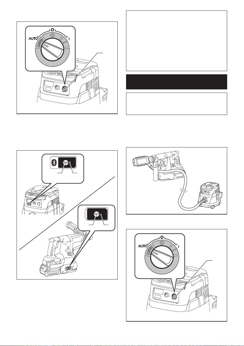
45 ESPAÑOL
2. Ajuste el interruptor de modo en espera en la aspi-
radora en “AUTO”.
1
► 1. Interruptor de modo en espera
3. Oprima el botón de activación inalámbrica en la
aspiradora durante 3 segundos hasta que la luz indica-
dora de activación inalámbrica parpadee en verde. Y
luego oprima el botón de activación inalámbrica en la
herramienta de la misma manera.
12
12
► 1. Botón de activación inalámbrica 2. Luz indica-
dora de activación inalámbrica
Si la aspiradora y la herramienta han sido conectadas
exitosamente, las luces indicadoras de activación ina-
lámbrica se encenderán en verde durante 2 segundos y
comenzarán a parpadear en azul.
NOTA: Las luces indicadoras de activación inalám-
brica terminarán parpadeando en verde después de
un lapso de 20 segundos. Oprima el botón de acti-
vación inalámbrica en la herramienta mientras la luz
indicadora de activación inalámbrica en la aspiradora
esté parpadeando. Si la luz indicadora de activación
inalámbrica no parpadea en verde, oprima el botón
de activación inalámbrica durante un lapso breve y
vuelva a mantenerlo oprimido.
NOTA: Cuando realice dos o más registros de la
herramienta para una aspiradora, termine el registro
de la herramienta de uno en uno.
Inicio de la función de activación
inalámbrica
NOTA: Termine con el registro de la herramienta para
la aspiradora antes de la activación inalámbrica.
NOTA: Consulte también el manual de instrucciones
de la aspiradora.
Después de registrar una herramienta en la aspiradora,
esta última se activará automáticamente junto con el
interruptor de la herramienta.
1. Instale la unidad inalámbrica en la herramienta.
2.
Conecte la manguera de la aspiradora a la herramienta.
3. Ajuste el interruptor de modo en espera en la aspi-
radora en “AUTO”.
1
► 1. Interruptor de modo en espera
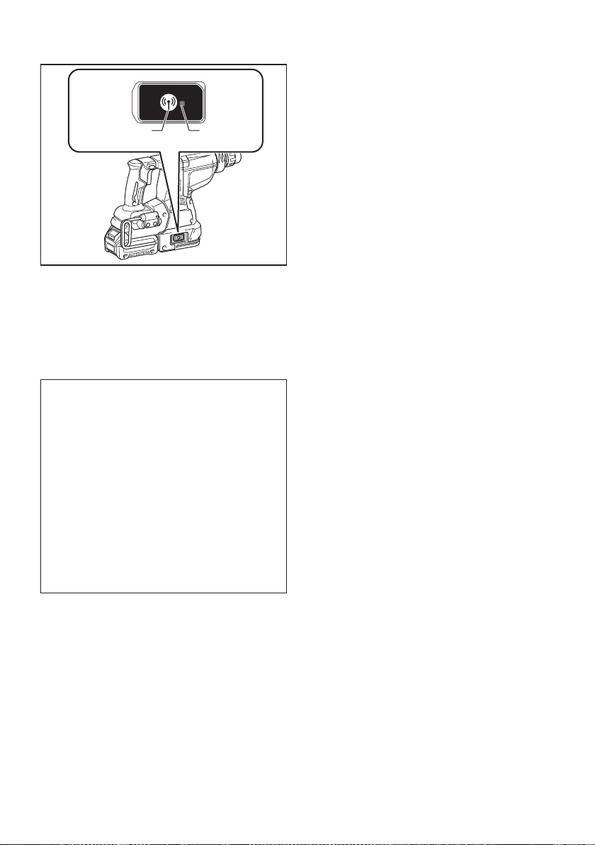
46 ESPAÑOL
4. Oprima el botón de activación inalámbrica en la
herramienta durante un lapso breve. La luz indicadora
de activación inalámbrica parpadeará en azul.
12
► 1. Botón de activación inalámbrica 2. Luz indica-
dora de activación inalámbrica
5. Jale el gatillo interruptor de la herramienta.
Verique que la aspiradora funcione mientras jala el
gatillo interruptor.
Para detener la activación inalámbrica de la aspira-
dora, oprima el botón de activación inalámbrica en la
herramienta.
NOTA: La luz indicadora de activación inalámbrica en
la herramienta dejará de parpadear en azul cuando
no haya operación durante 2 horas. En este caso,
ajuste el interruptor de modo en espera en la aspi-
radora en “AUTO” y oprima el botón de activación
inalámbrica en la herramienta nuevamente.
NOTA: La aspiradora funcionará/detendrá con un
retraso. Existirá un desfase cuando la aspiradora
detecte la activación del interruptor de la herramienta.
NOTA: La distancia de transmisión de la unidad
inalámbrica podrá variar en función del lugar y las
circunstancias de los alrededores.
NOTA: Cuando dos o más herramientas estén
registradas en una aspiradora, esta última podrá
comenzar a funcionar incluso si usted no jala el gatillo
interruptor debido a que otro usuario está utilizando
la función de activación inalámbrica.
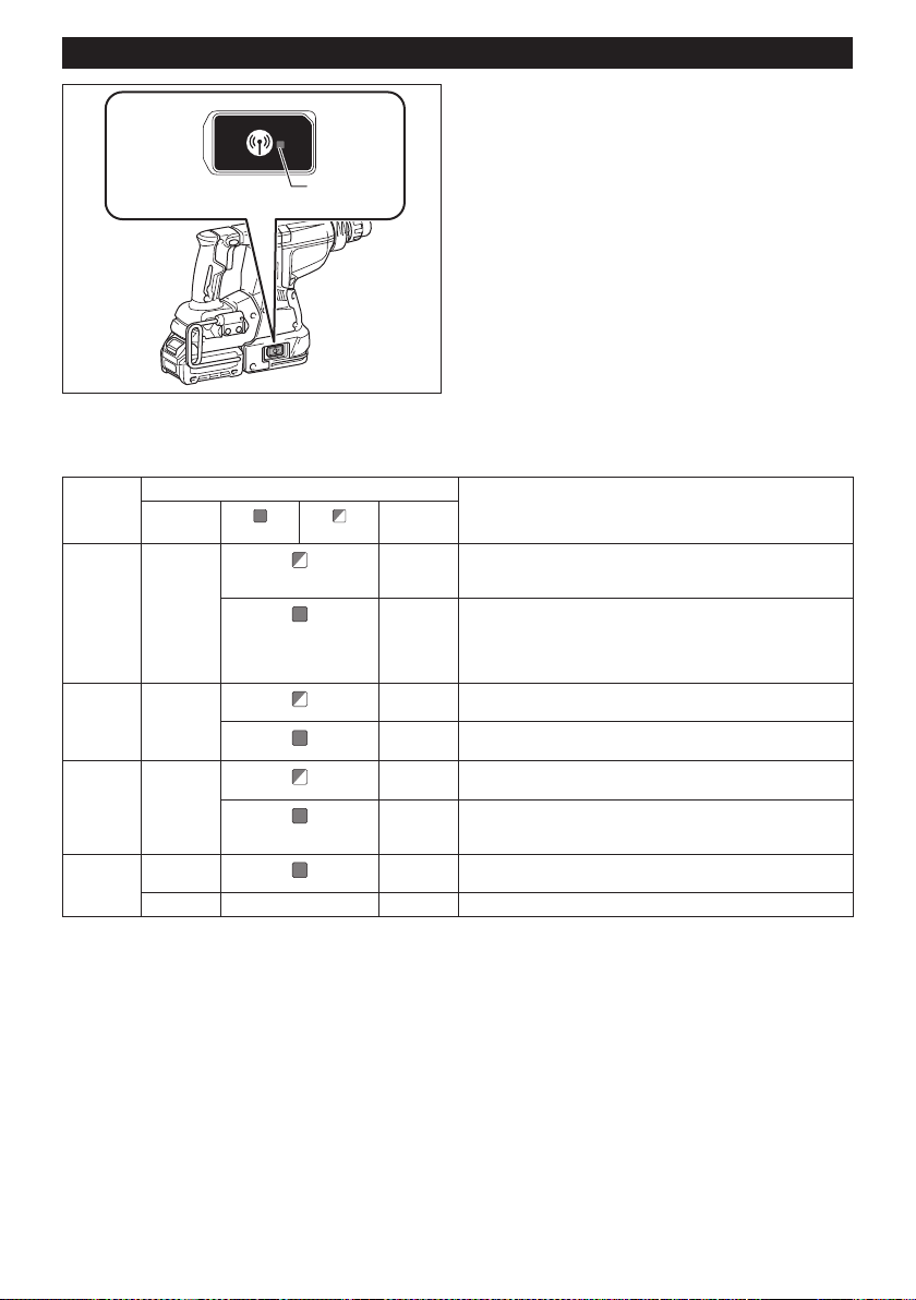
47 ESPAÑOL
Descripción del estado de la luz indicadora de activación inalámbrica
1
► 1. Luz indicadora de activación inalámbrica
La luz indicadora de activación inalámbrica muestra el estado de la función de activación inalámbrica. Consulte la
tabla a continuación para ver qué signica el estado de la luz indicadora.
Estado Luz indicadora de activación inalámbrica Descripción
Color
Encendida
Parpadeando
Duración
En espera Azul
2 horas La activación inalámbrica de la aspiradora está disponible. La
luz se apagará automáticamente cuando no se realice ninguna
operación durante 2 horas.
Cuando
la herra-
mienta
está fun-
cionando.
La activación inalámbrica de la aspiradora está disponible y la
herramienta está funcionando.
Registro
de la
herramienta
Verde
20
segundos
Ya se puede realizar el registro de la herramienta. Esperando el
registro por parte de la aspiradora.
2
segundos
El registro de la herramienta ha terminado. La luz indicadora de
activación inalámbrica comenzará a parpadear en azul.
Cancelación
del regis-
tro de la
herramienta
Rojo 20
segundos
Ya se puede cancelar el registro de la herramienta. Esperando la
cancelación por parte de la aspiradora.
2
segundos
La cancelación del registro de la herramienta ha terminado. La
luz indicadora de activación inalámbrica comenzará a parpadear
en azul.
Otros Rojo
3
segundos
La energía es suministrada a la unidad inalámbrica y la función
de activación inalámbrica está arrancando.
Apagada - - La activación inalámbrica de la aspiradora se ha detenido.

48 ESPAÑOL
Cancelación del registro de la
herramienta para la aspiradora
Realice el siguiente procedimiento para cancelar el
registro de la herramienta para la aspiradora.
1. Instale las baterías en la aspiradora y en la
herramienta.
2. Ajuste el interruptor de modo en espera en la aspi-
radora en “AUTO”.
1
► 1. Interruptor de modo en espera
3.
Oprima el botón de activación inalámbrica en la
aspiradora durante 6 segundos. La luz indicadora de acti-
vación inalámbrica parpadeará en verde y luego se pondrá
en rojo. Después de eso, oprima el botón de activación
inalámbrica en la herramienta de la misma manera.
12
12
► 1. Botón de activación inalámbrica 2. Luz indica-
dora de activación inalámbrica
Si la cancelación se realiza exitosamente, las luces
indicadoras de activación inalámbrica se encenderán
en rojo durante 2 segundos y comenzarán a parpadear
en azul.
NOTA: Las luces indicadoras de activación inalám-
brica terminarán parpadeando en rojo después de un
lapso de 20 segundos. Oprima el botón de activación
inalámbrica en la herramienta mientras la luz indi-
cadora de activación inalámbrica en la aspiradora
esté parpadeando. Si la luz indicadora de activación
inalámbrica no parpadea en rojo, oprima el botón
de activación inalámbrica durante un lapso breve y
vuelva a mantenerlo oprimido.

49 ESPAÑOL
Detección y solución de problemas para la función de activación inalámbrica
Antes de solicitar alguna reparación, primero realice una inspección por su cuenta. Si detecta algún problema que
no esté explicado en el manual, no intente desensamblar la herramienta. En vez de esto, solicite la reparación a un
centro de servicio autorizado de Makita, usando siempre piezas de repuesto Makita.
Estado de la anomalía Causa probable (avería) Remedio
La luz indicadora de activación ina-
lámbrica no enciende/parpadea.
La unidad inalámbrica no está instalada
en la herramienta.
La unidad inalámbrica está instalada
incorrectamente en la herramienta.
Instale la unidad inalámbrica correctamente.
La terminal de la unidad inalámbrica y/o
la ranura está sucia.
Retire con cuidado el polvo y la suciedad en la
terminal de la unidad inalámbrica y limpie la ranura.
El botón de activación inalámbrica en la
herramienta no se ha oprimido.
Oprima el botón de activación inalámbrica en la
herramienta durante un lapso breve.
El interruptor de modo en espera en la
aspiradora no está ajustado en “AUTO”.
Ajuste el interruptor de modo en espera en la
aspiradora en “AUTO”.
No hay suministro de energía. Suministre energía a la herramienta y a la
aspiradora.
No se puede terminar/cancelar
el registro de la herramienta
exitosamente.
La unidad inalámbrica no está instalada
en la herramienta.
La unidad inalámbrica está instalada
incorrectamente en la herramienta.
Instale la unidad inalámbrica correctamente.
La terminal de la unidad inalámbrica y/o
la ranura está sucia.
Retire con cuidado el polvo y la suciedad en la
terminal de la unidad inalámbrica y limpie la ranura.
El interruptor de modo en espera en la
aspiradora no está ajustado en “AUTO”.
Ajuste el interruptor de modo en espera en la
aspiradora en “AUTO”.
No hay suministro de energía. Suministre energía a la herramienta y a la
aspiradora.
Operación incorrecta Oprima el botón de activación inalámbrica durante
un lapso breve y realice los procedimientos de
registro/cancelación de la herramienta nuevamente.
La herramienta y la aspiradora están
lejos una de la otra (fuera del rango de
transmisión).
Acerque más la herramienta a la aspiradora. La
distancia máxima de transmisión es de aproxima-
damente 10 m, pero puede variar en función de las
circunstancias.
Antes de terminar el registro/cancela-
ción de la herramienta;
- el gatillo interruptor en la herramienta
se ha jalado; o
- el botón de encendido en la aspira-
dora está activado.
Oprima el botón de activación inalámbrica durante
un lapso breve y realice los procedimientos de
registro/cancelación de la herramienta nuevamente.
Los procedimientos de registro para
la herramienta o aspiradora no se han
terminado.
Realice los procedimientos de registro tanto para
la herramienta como para la aspiradora al mismo
tiempo.
La perturbación radioeléctrica generada
por otros aparatos que emiten ondas de
radio de alta intensidad.
Mantenga la herramienta y la aspiradora lejos de
aparatos tales como dispositivos Wi-Fi y hornos de
microondas.
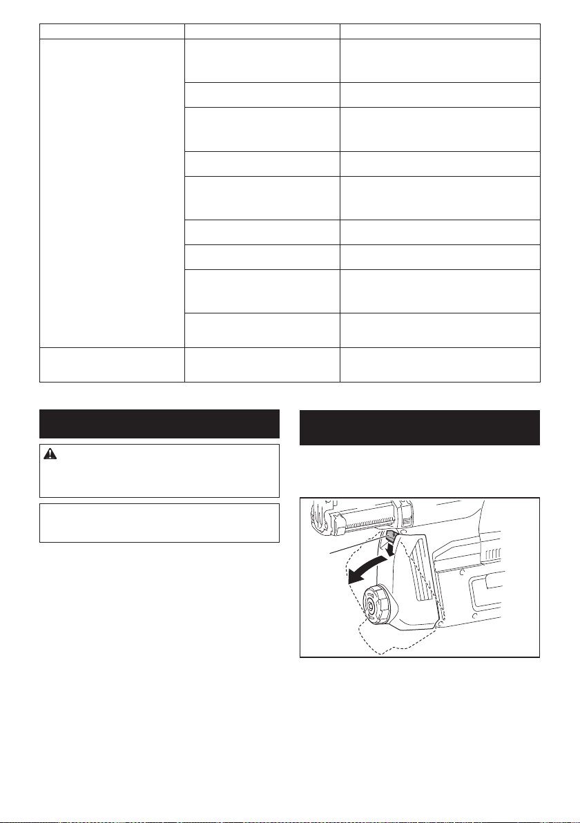
50 ESPAÑOL
Estado de la anomalía Causa probable (avería) Remedio
La aspiradora no funciona junto con
el interruptor de la herramienta.
La unidad inalámbrica no está instalada
en la herramienta.
La unidad inalámbrica está instalada
incorrectamente en la herramienta.
Instale la unidad inalámbrica correctamente.
La terminal de la unidad inalámbrica y/o
la ranura está sucia.
Retire con cuidado el polvo y la suciedad en la
terminal de la unidad inalámbrica y limpie la ranura.
El botón de activación inalámbrica en la
herramienta no se ha oprimido.
Oprima el botón de activación inalámbrica durante
un lapso breve y asegúrese de que la luz indicadora
de activación inalámbrica esté parpadeando en
azul.
El interruptor de modo en espera en la
aspiradora no está ajustado en “AUTO”.
Ajuste el interruptor de modo en espera en la
aspiradora en “AUTO”.
Más de 10 herramientas están registra-
das en la aspiradora.
Vuelva a realizar el registro de la herramienta.
Si más de 10 herramientas están registradas en la
aspiradora, la herramienta registrada al principio se
cancelará automáticamente.
La aspiradora borró todos los registros
de la herramienta.
Vuelva a realizar el registro de la herramienta.
No hay suministro de energía. Suministre energía a la herramienta y a la
aspiradora.
La herramienta y la aspiradora están
lejos una de la otra (fuera del rango de
transmisión).
Acerque más la herramienta a la aspiradora. La
distancia máxima de transmisión es de aproxima-
damente 10 m, pero puede variar en función de las
circunstancias.
La perturbación radioeléctrica generada
por otros aparatos que emiten ondas de
radio de alta intensidad.
Mantenga la herramienta y la aspiradora lejos de
aparatos tales como dispositivos Wi-Fi y hornos de
microondas.
La aspiradora funciona aun cuando
el gatillo interruptor de la herra-
mienta no ha sido jalado.
Otros usuarios están usando la activa-
ción inalámbrica de la aspiradora con
sus herramientas.
Apague el botón de activación inalámbrica de las
demás herramientas o cancele el registro de dichas
herramientas.
MANTENIMIENTO
PRECAUCIÓN: Asegúrese siempre de que la
herramienta esté apagada y el cartucho de batería
extraído antes de intentar realizar una inspección
o mantenimiento.
AVISO: Nunca use gasolina, bencina, diluyente
(tíner), alcohol o sustancias similares. Puede que
esto ocasione grietas o descoloramiento.
Para mantener la SEGURIDAD y FIABILIDAD del pro-
ducto, las reparaciones, y cualquier otra tarea de man-
tenimiento o ajuste deberán ser realizadas en centros
de servicio autorizados o de fábrica Makita, empleando
siempre repuestos Makita.
Reemplazo del ltro de la caja para
polvo
Accesorio opcional
1. Extraiga la caja para polvo mientras presiona
hacia abajo la palanca de la caja para polvo.
1
► 1. Palanca
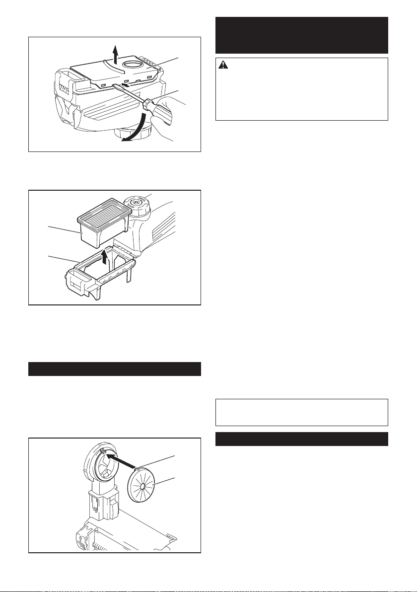
51 ESPAÑOL
2.
Inserte un destornillador de punta plana en las ranu-
ras de la cubierta del ltro para extraer la cubierta del ltro.
2
1
► 1. Destornillador de punta plana 2. Cubierta del
ltro
3. Extraiga el ltro de la caja del ltro.
1
2
► 1. Filtro 2. Caja del ltro
4. Coloque un ltro nuevo en la caja del ltro y luego
je la cubierta del ltro.
5. Cierre la cubierta de la caja para polvo y luego
fíjela en el sistema de recolección de polvo.
Reemplazo del tapón sellador
Accesorio opcional
Si el tapón sellador está desgastado, el desempeño de
la recolección de polvo se verá reducido. Reemplácelo
si presenta indicios de desgaste.
Retire el tapón sellador y luego coloque uno nuevo con
su protuberancia orientada hacia arriba.
1
2
► 1. Protuberancia 2. Tapón sellador
ACCESORIOS
OPCIONALES
PRECAUCIÓN: Estos accesorios o aditamen-
tos están recomendados para utilizarse con su
herramienta Makita especicada en este manual.
El empleo de cualquier otro accesorio o aditamento
puede conllevar el riesgo de lesiones personales.
Utilice los accesorios o aditamentos solamente para
su n establecido.
Si necesita cualquier ayuda para más detalles en
relación con estos accesorios, pregunte a su centro de
servicio local Makita.
• Brocas con puntas de carburo (puntas de carburo
SDS-Plus)
• Punta de corona
• Cincel de punta
• Punta de corona de diamante
• Cincel plano
• Cincel de desincrustación
• Cincel de ranurado
• Adaptador de mandril
• Portabrocas adaptador sin llave
• Grasa para puntas
• Calibrador de profundidad
• Soplador
• Contenedor de polvo
• Juego contenedor de polvo
• Conjunto de ganchos
• Conjunto de caja para polvo
• Conjunto de mandril de taladro
• Conjunto del ltro
• Conjunto de soportes de la herramienta
• Conjunto de juntas
• Sistema de recolección de polvo
• Unidad inalámbrica
• Batería y cargador originales de Makita
• Gafas de seguridad
• Maletín de transporte de plástico
NOTA: Algunos de los artículos en la lista pueden
incluirse en el paquete de la herramienta como acce-
sorios estándar. Éstos pueden variar de país a país.
GARANTÍA LIMITADA DE MAKITA
Ésta Garantía no aplica para México
Consulte la hoja de la garantía anexa para ver los
términos más vigentes de la garantía aplicable a este
producto. En caso de no disponer de esta hoja de
garantía anexa, consulte los detalles sobre la garantía
descritos en el sitio web de su país respectivo indicado
a continuación.
Estados Unidos de América: www.makitatools.com
Canadá: www.makita.ca
Otros países: www.makita.com

Some dust created by power sanding, sawing, grinding, drilling, and other
construction activities contains chemicals known to the State of California
to cause cancer, birth defects or other reproductive harm. Some examples
of these chemicals are:
• lead from lead-based paints,
• crystalline silica from bricks and cement and other masonry products, and
• arsenic and chromium from chemically-treated lumber.
Your risk from these exposures varies, depending on how often you do this
type of work. To reduce your exposure to these chemicals: work in a well
ventilated area, and work with approved safety equipment, such as those
dust masks that are specially designed to filter out microscopic particles.
WARNING
< USA only >
ADVERTENCIA
Algunos polvos creados por el lijado, aserrado, esmerilado, taladrado y
otras actividades de la construcción contienen sustancias químicas
reconocidas por el Estado de California como causantes de cáncer, defectos
de nacimiento y otros peligros de reproducción. Algunos ejemplos de estos
productos químicos son:
• plomo de pinturas a base de plomo,
• sílice cristalino de ladrillos y cemento y otros productos de albañilería, y
• arsénico y cromo de maderas tratadas químicamente.
El riesgo al que se expone varía, dependiendo de la frecuencia con la que
realice este tipo de trabajo. Para reducir la exposición a estos productos
químicos: trabaje en un área bien ventilada y póngase el equipo de seguridad
indicado, tal como las máscaras contra polvo que están especialmente
diseñadas para filtrar partículas microscópicas.
< Sólo en los Estados Unidos >
Makita Corporation
3-11-8, Sumiyoshi-cho,
Anjo, Aichi 446-8502 Japan
www.makita.com
885753A947
GRH01-1
EN, ESMX
20190827