
Loading ...
Loading ...
Loading ...
HEATIZON.COM
14
5. INSTALLATION
Follow these steps to ensure a successful Heatwave®
installation.
5.1.1 PLAN THE LAYOUT
Using the back page of this manual, make a sketch layout or a floor
plan of the room; include all permanent furnishings such as toilets,
bathtubs, appliances, cabinetry, etc. Indicate all dimensions required to
determine the available floor area and the position of the thermostat.
Important: Tools and materials required
The following items may be required to install and test the floor heating system:
• Scissors • Tape measure • Hot glue gun • Utility knife
• Screwdriver • Tin snips • Wire strippers • Multimeter
• Heatizon Plastic Cable Clips or Cable Strap
Heatizon recommends that the installation be documented with photos and drawings
to note the location of connections and the sensor, as well as the cable layout.
NOTE:
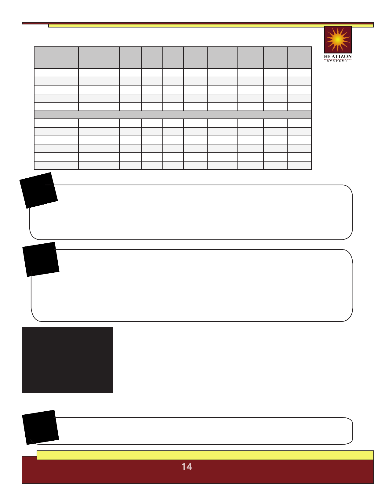
Heatwave® Cables, 120/240 VAC
Heatizon Part
Number
120V Input
Manufacturer
Number
Total
Watts
Total
Ohms
Amp
Load
Watts/
Foot
Coverage
Area/Square
Foot
Watts/
Square
Foot
Cable
Length
Cable
spacing
(O.C.)
HWC-815 HWC2012-44 120 120.0 1.0 2.73 8-15 14-8 44’ 2.5-4.5”
HWC-1630 HWC2012-77 240 60.0 2.0 3.12 16-30 14-8 77’ 2.5-4.5”
HWC-3260 HWC2012-154 480 30.0 4.0 3.12 32-60 14-8 154’ 2.5-4.5”
HWC-5094 HWC2012-203 750 19.2 6.3 3.69 50-94 14-8 203’ 2.5-4.5”
HWC-64120 HWC2012-362 960 15.0 8.0 2.65 64-120 14-8 362’ 2.5-4.5”
240V Input
HWC-1631B HWC2024-86 245 235.1 1.0 2.85 16-31 14-8 86’ 2.5-4.5”
HWC-3260B HWC2024-110 480 120.0 2.0 4.36 32-60 14-8 110’ 2.5-4.5”
HWC-56105B HWC2024-242 840 68.6 3.5 3.47 56-105 14-8 242’ 2.5-4.5”
HWC-80150B HWC2024-375 1200 48.0 5.0 3.20 80-150 14-8 375’ 2.5-4.5”
HWC-114214B HWC2024-564 1710 33.7 7.1 3.03 114-214 14-8 564’ 2.5-4.5”
HWC-128239B HWC2024-726 1915 30.1 8.0 2.64 128-239 14-8 726’ 2.5-4.5”
Before Laying the Heatwave® Mat or Cable
Note: Measure the resistance between each conductor and the shielding/ground
wire. Both should read infinity. Always complete a Heatizon Systems “Resistance in
OHMS Form” (see form in the back of this manual) out of the box, immediately following
the installation of the Heatwave® Heating Cable/Mat, immediately prior to covering the
Heatwave® Heating Cable/Mat, and again just prior to energizing the Heatwave® Heating
Cable/Mat.
NOTE:
Loading ...
Loading ...
Loading ...