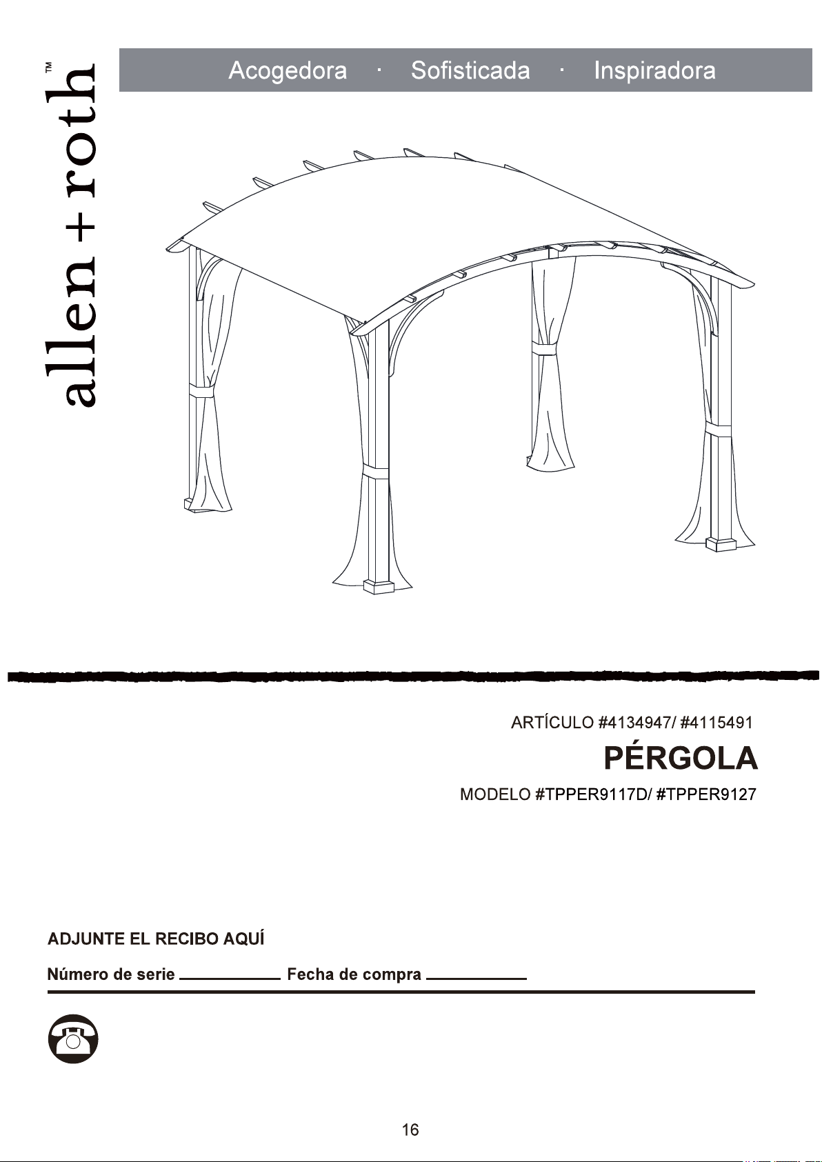
Questions, problems, missing parts? Before returning to your retailer, call our customer
service department at 1-866-439-9800, 8 a.m. - 8 p.m., ES T, Monday - Sunday. You could
ALLEN + ROTH and logo design are trademarks
or registered trademarks of LF, LLC.
All Rights Reserved.
AS21328
also contact us at partsplus@lowes.com or visit www.lowespartsplus.com.
2
TABLE OF CONTENTS
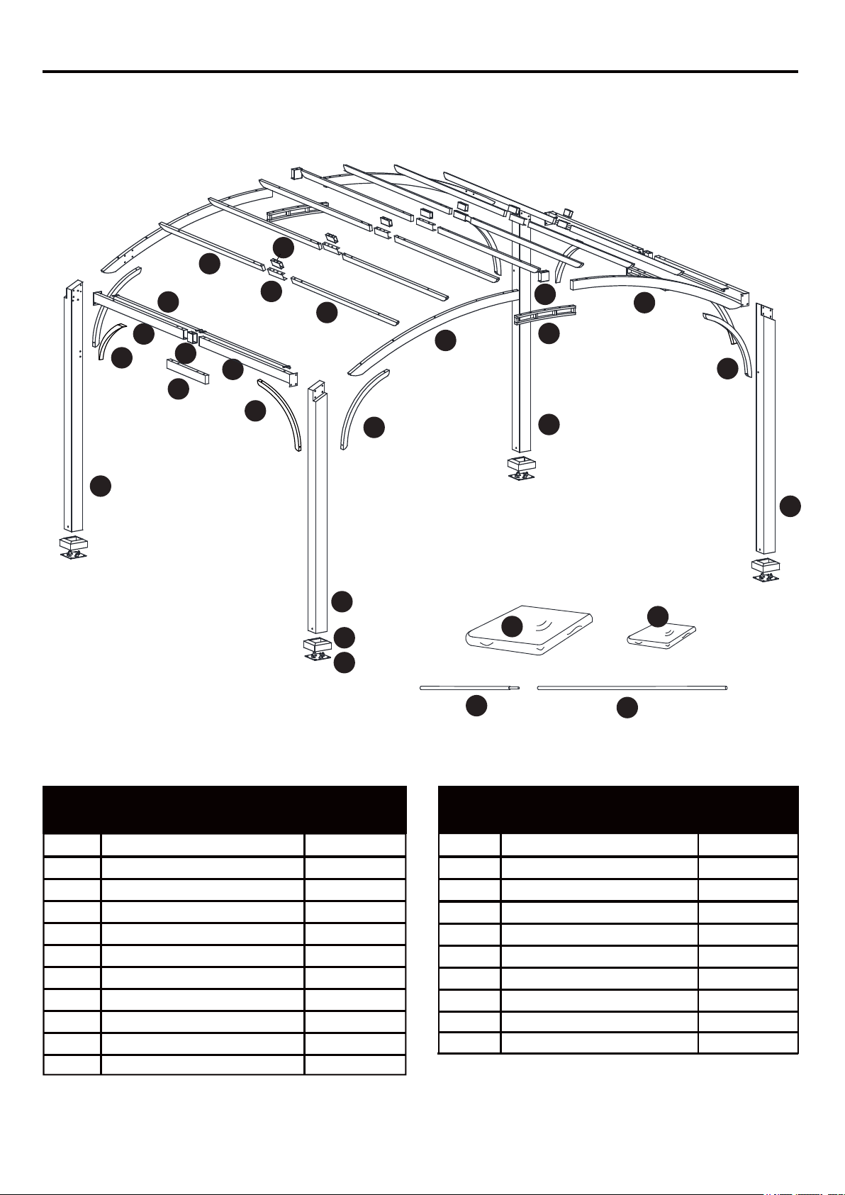
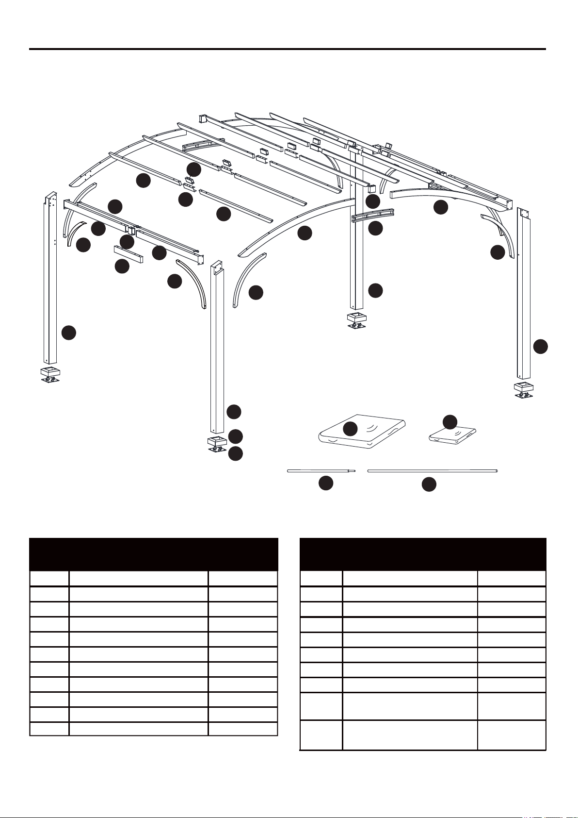
Post
Post
Arc Beam
Arc Beam
Beam
Beam
Connector
Connector
Arc Connector
Ferrule
Ferrule
A1
A2
B1
B2
C1
C2
E1
E2
D
F1
F22
2
2
2
2
2
Top Beam
D1
14
2
2
3
7
4
7
Support Bar
Support Bar
Base Cover
Base
Sidewall Rod
Sidewall
Canopy
4
4
4
2
2
2
1
G1
G
H
I
J
K
L
M1
M2
F1
K
A1
L
A1
B1
F1
C1
B2
A2
G
A2
C2
D1
D1
E1
E2
D
F2
G1
G
H
I
M1
M2
J
Canopy Holding Rod
Canopy Holding Rod
4
4
G1
PACKAGE CONTENTS
PART DESCRIPTION
QUANTITY
PART DESCRIPTION
QUANTITY
Allen Wrench
AA CC
GG
BB DD EE
JJ KKII
Stake
Qty. 16
(NOT TO SCALE)
LL
Qty. 1
(NOT TO SCALE)
HARDWARE CONTENTS (shown actual size)
HH
MM
FF
KEEP ALL FLAME AND HEAT AWAY FROM THIS GAZEBO FABRIC.
Please read and understand this entire manual before attempting to assemble or install the product.
Three people are need for assembly.
SAFETY INFORMATION
WARNING:
CAUTION
PREPARTION
This gazebo meets the flammability requirements of CPAI-84 The fabric may burn if left in
continuous contact with any flame source. The application of any foreign substance to the
gazebo fabric may render the flame-resistant properties ineffective.
Do not leave outside during high winds, heavy rains or snow. If high winds, heavy rains or any
snow occurs, remove canopy and Sidewall, clear snow load from roof, and check for damage
before continued use.
Before beginning assembly of product, make sure all parts are presented. Compare parts with
package contents list and hardware contents list. If any part is missing or damaged, do not attempt
to assemble the product.
Estimated Assembly Time: 50minutes
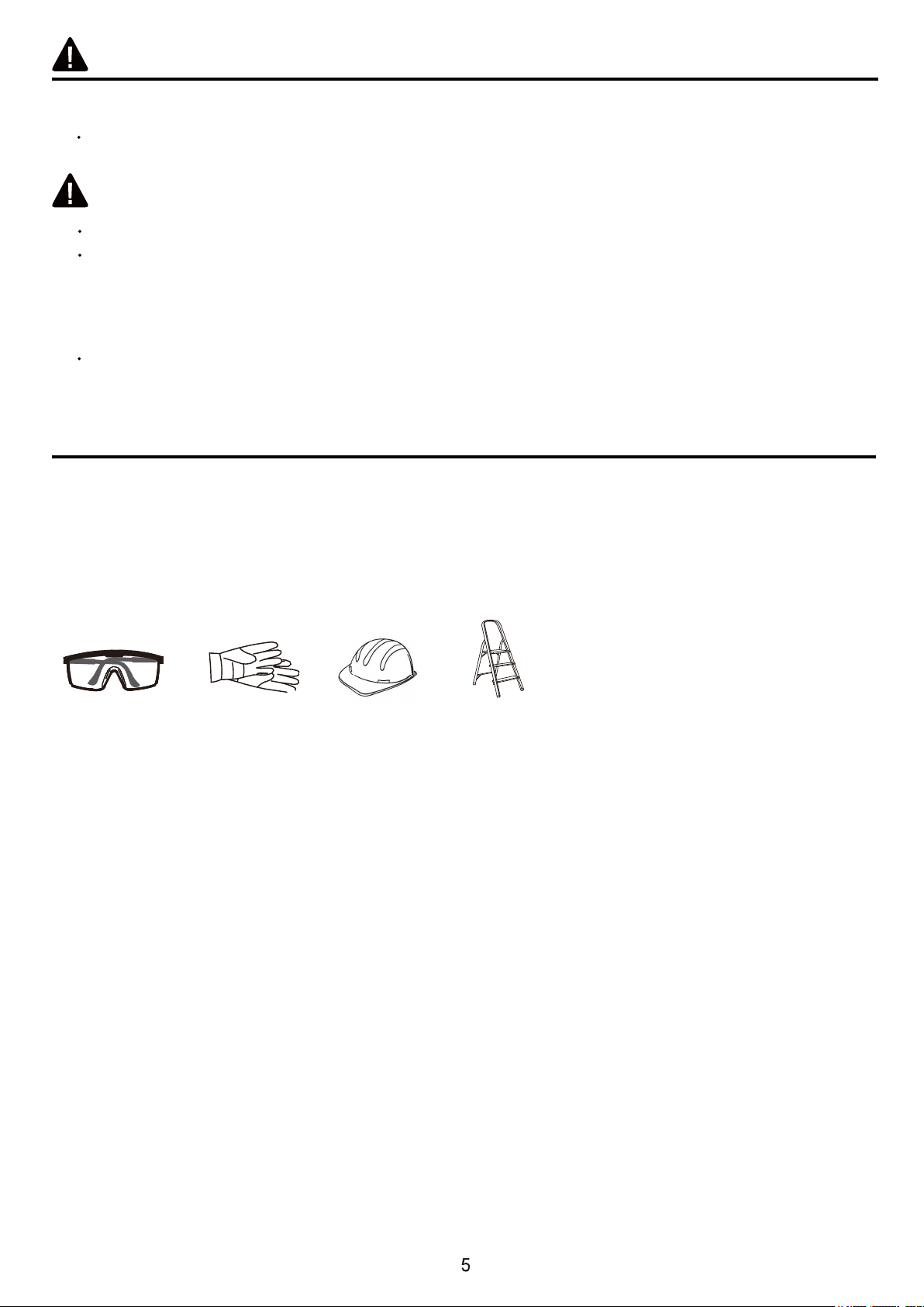
Tools Required for Assembly (included): Wrench
Tools Required for Assembly (not included): Safety goggles, Gloves, Hardhat, Stepladder.
Safety goggles
Gloves
Stepladder
Hardhat
A1
A1
A2
A2
A1
H
I
AA
HH
AA
HH
EE
EE
A2
1
AA
EE
JJ
HH
H
B1
B2
B2
B1
C1
C2
C1
C2
ASSEMBLY INSTRUCTIONS
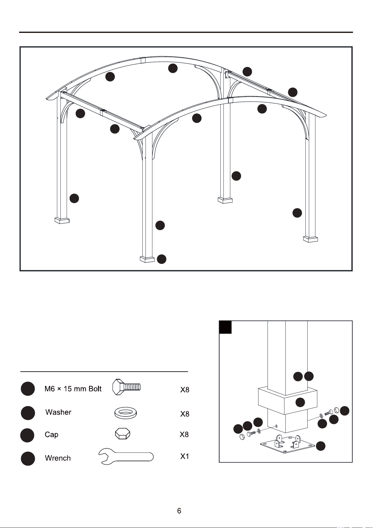
1. Insert the posts (A1/A2) into the base cover (H),
then attach the bases (I) to the posts (A1/A2)
using bolts (AA) and washers (EE). Tighten with
wrench (JJ). Place cap (HH) on the bolt heads.
Hardware Used
ASSEMBLY INSTRUCTIONS
Hardware Used
Hardware Used
AA
FF
HH
JJ
AA
JJ
HH
FF
AA
FF
HH
C1
C1
C2
C1
F1
F1
2
4
3
E1
E1
AA
FF
HH
C2
C1
F1
AA
FF
HH
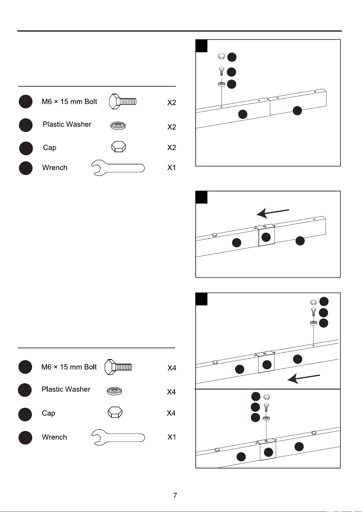
2. Insert the connectors (E1) to the beams (C1),
secure with bolts (AA) and plastic washers (FF),
tighten with wrench (JJ). Place cap (HH) on the
bolt heads.
3. Attach the ferrule (F1) to the beam
assemblies (C1/E1).
4. Attach the beams (C2) to the beam assemblies
(C1/E1/F1) and secure with bolts (AA) and
plastic washers (FF), tighten with wrench (JJ).
Place cap (HH) on the bolt heads.
Hardware Used
AA
JJ
7
6
B1
E2
E2
F1
B1
FF
HH
AA
FF
HH
AA
FF
HH
Hardware Used
AA
JJ
FF
HH
5
AA
FF
F1
HH
AA
FF
HH
C1
J
J
C2
C2
J
ASSEMBLY INSTRUCTIONS
5. Attach the sidewall rod (J) to the beam (C1/C2),
secure with bolts (AA) and plastic washers (FF),
tighten with wrench (JJ). Place cap (HH) on the
bolt heads.
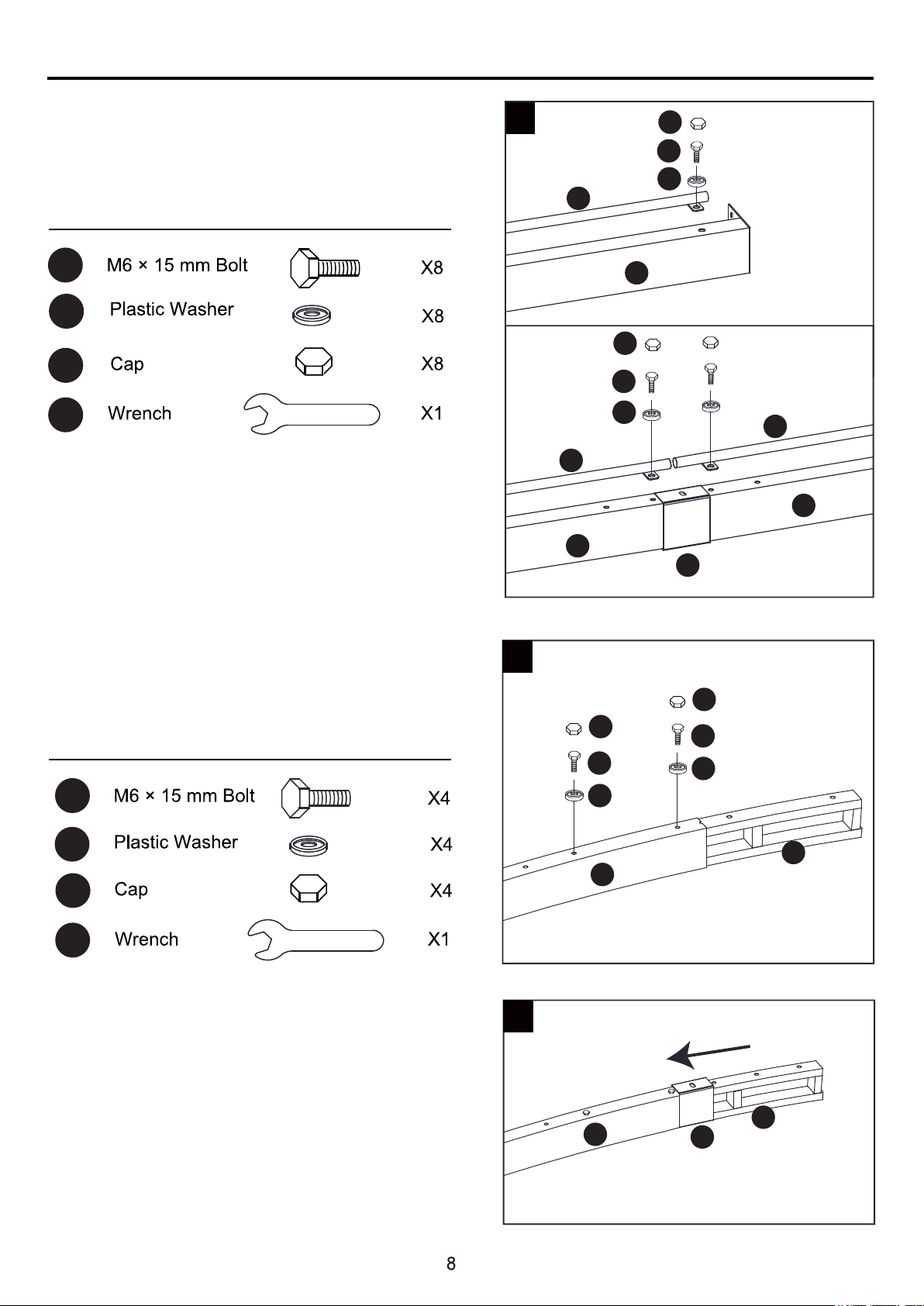
6. Insert arc connectors (E2) to the arc beams (B1),
secure with bolts (AA) and plastic washers (FF),
tighten with wrench (JJ). Place cap (HH) on the
bolt heads.
7. Attach the ferrule (F1) to the beam
assemblies (B1/E2).
ASSEMBLY INSTRUCTIONS
Hardware Used
Hardware Used
Hardware Used
AA
JJ
BB
LL
EE
HH
AA
JJ
FF
HH
F1
LL
BB
BB
B1
B2
A1
A2
A1
B1
B2
A2
A2
B2
A1
B1 B2
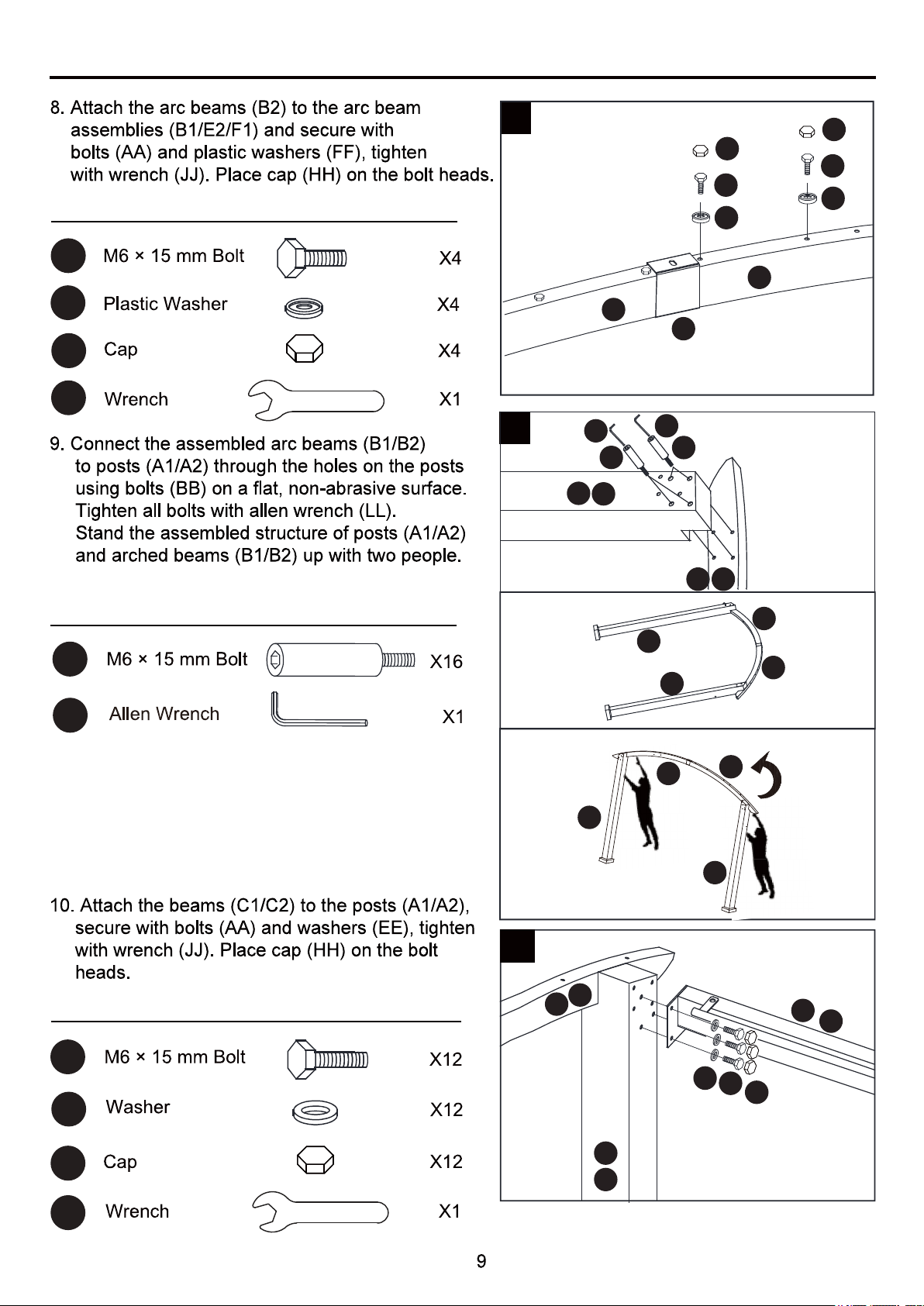
8
9
AA
FF
HH
AA
FF
HH
10
AA
EE
HH
LL
A1
A2
B1
B2
C2
C1
B1

ASSEMBLY INSTRUCTIONS
MM
HH
Hardware Used
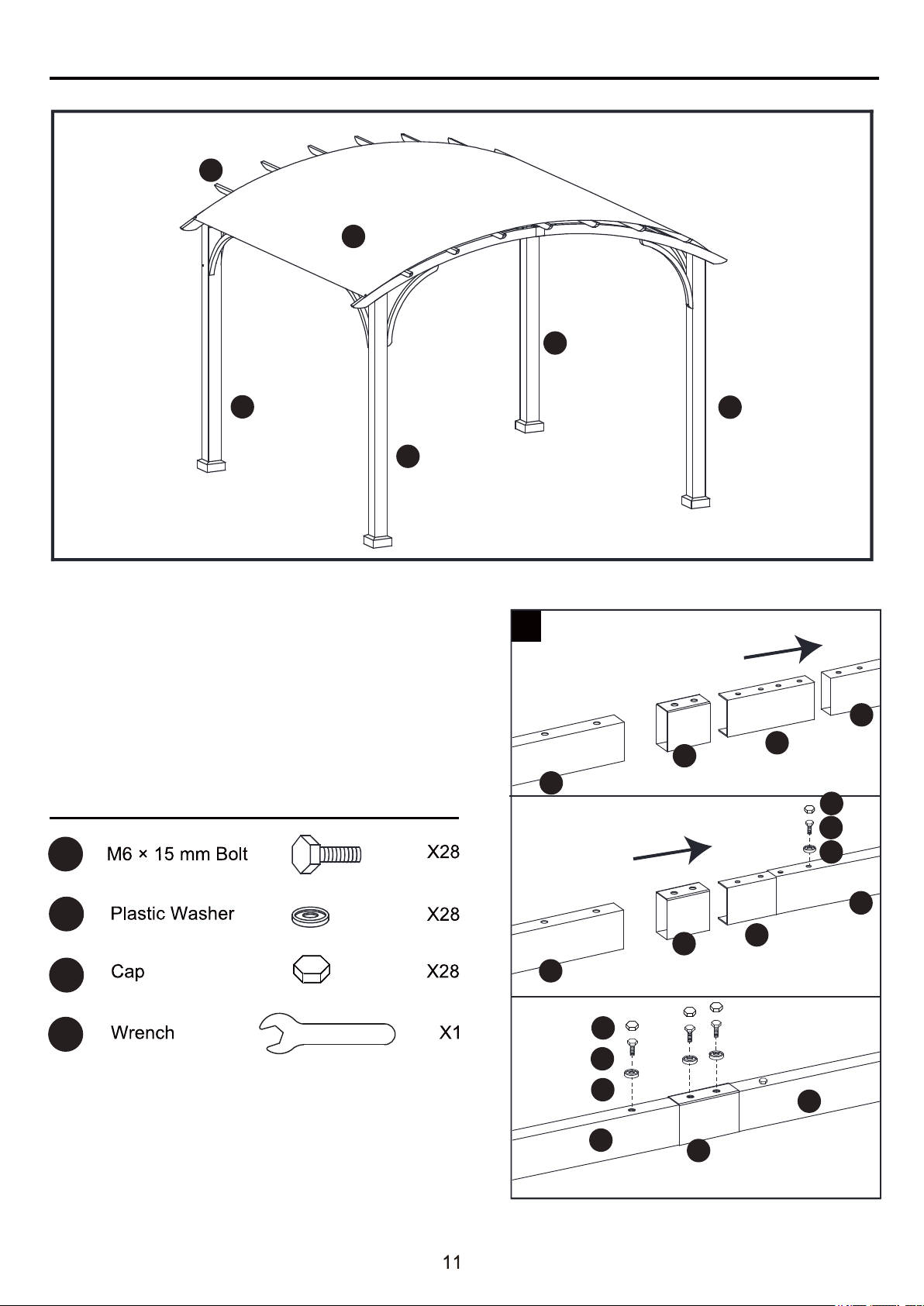
and the beams (C1/C2) using bolts (CC) and
washers (EE), tighten with wrench (JJ). Repeat this
step for attaching the supports bar (G1) to the posts
(A1/A2) and the arc beams (B1/B2) using bolts (CC)
and washers (EE), tighten with wrench (JJ). Place cap
(HH) on the bolt heads.
Place the cap (MM) on the inside of the posts (A1/A2).
11. Attach the supports bar (G) to the posts (A1/A2)
CC
EE
JJ
11
EE
EE
HH
HH
CC
CC
A1
A2
B1 B2
C2
C1
G2
G1
G
MM
A1
A2
C1
C2
B1 B2
A1
A1
A2
A2
H
G1
C1
C2
C1
C2
G
G
B2
B1
G
G
G1
G1
B1
B2
A1
ASSEMBLY INSTRUCTIONS
Hardware Used
12. Insert connectors (D) to the top beams (D1),
secure with bolts (AA) and plastic washers (FF).
Attach the ferrule (F2) and the top beams (D1)
to the beam assemblies (D1/D) and secure with
bolts (AA) and plastic washers (FF), tighten with
wrench (JJ). Place cap (HH) on the bolt heads.
AA
JJ
HH
FF
12
D1
D1
F2
D1
F2
D
D
D1
AA
FF
HH
A1
A1
K
D
A2
A2
D1
D1
F2
HH
AA
FF
ASSEMBLY INSTRUCTIONS
Hardware Used
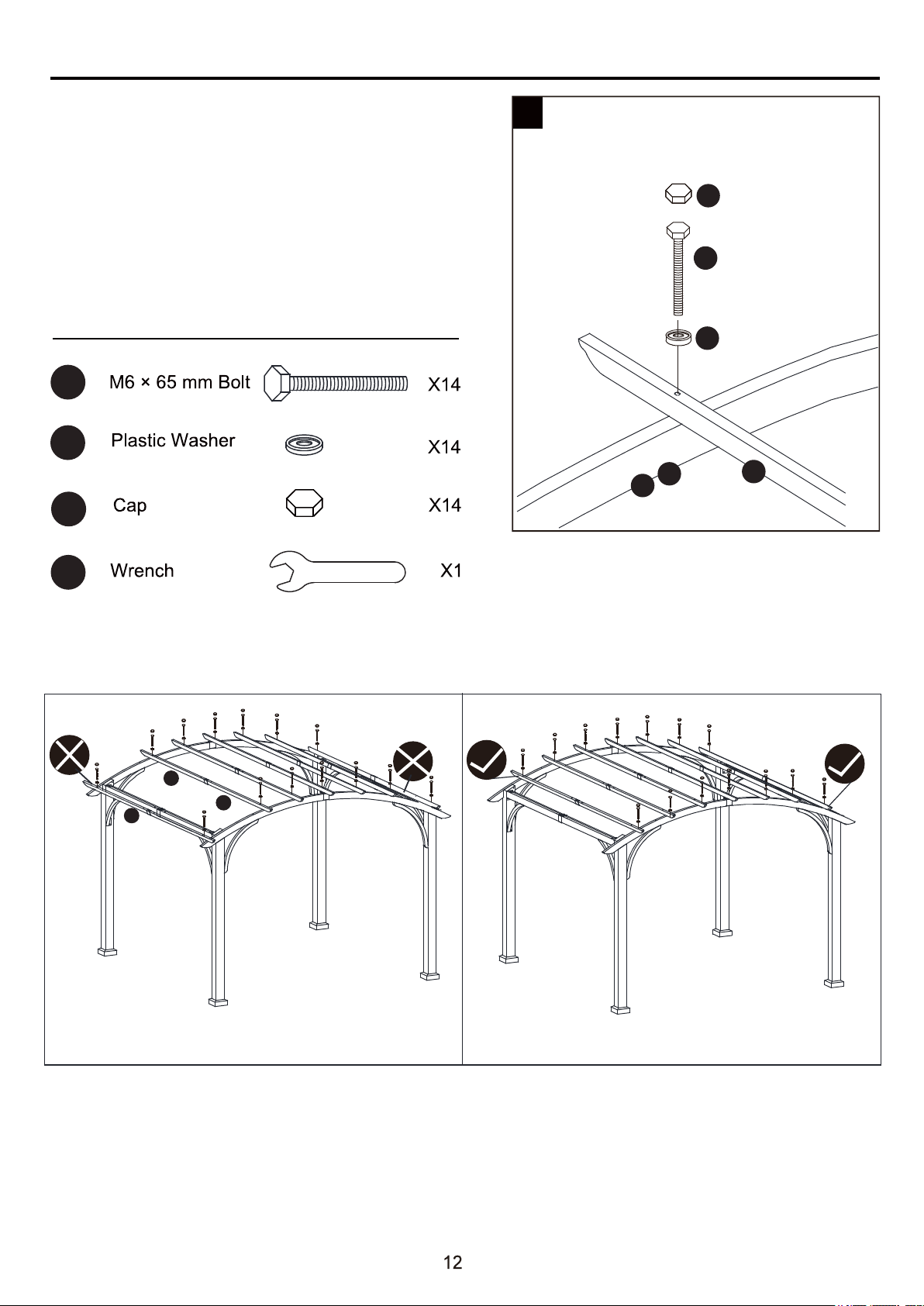
13. Attach the assembled top beams (D1) to
the arc beams (B1/B2) using bolts (DD) and
plastic washers (FF), tighten with wrench (JJ).
Place cap (HH) on the bolt heads.
Note: Don’t attach the assembled top
beams (D1) to the holes on the outside
of the arc beams (B1/B2).
13
B1
B2
DD
FF
HH
D1
HH
DD
JJ
FF
D1
D1
D1

ASSEMBLY INSTRUCTIONS
Hardware Used
Hardware Used
Hardware Used
16. Lift the base covers (H) and secure
the assembled pergola to the ground
with stakes (KK).
Your pergola is now fully assembled.
A1
KK
KK
I
A2
16
15
KK
KK
14. Connect canopy holding rod (M1)
and canopy holding rod (M2),
insert the assembed canopy holding
rod (M1/M2) into the canopy (K),
then secure the rod onto the
arc beam (B1/B2) with the bolt (GG).
15. Put the sidewall (L) onto the sidewall
rod (J) by the rings (II), then secure
it onto the posts (A1/A2).
GG
II
A1
A2
14
K
L
J
II
M1
M2
K
M1
M2
K
GG

CARE AND MAINTENANCE
WARRANTY
1 YEAR WARRANTY FOR FRAME AND FABRIC.
WHAT IS COVERED
We provide warranty to the original purchase for 1 year for frame and fabric from the date of
purchase, and the fabric and frame will be replaced at no charge due to manufacturing defects.
WHAT IS NOT COVERED
We do not reimburse for transportation costs. This warranty does not cover the damage caused
by commercial use, acts of nature, fire, freezing, and abusive use. Discoloration or fading of the
finish or fabrics as a result of chemicals or spills is not covered.
Contact the Customer Service Team at 1-866-439-9800.
For cleaning, use a mild detergent solution, rinse with water, and allow to air dry.
Do not use acetone, abrasive, or other special detergents as they would be harmful to the
product’s finish.
Due to the nature of steel, surface oxidation (rusting) will occur if this protective coating is scratched.
This is a natural process. To minimize this condition, it is recommended that care be taken when
assembling and handling the product in order to prevent the paint from being scratched.
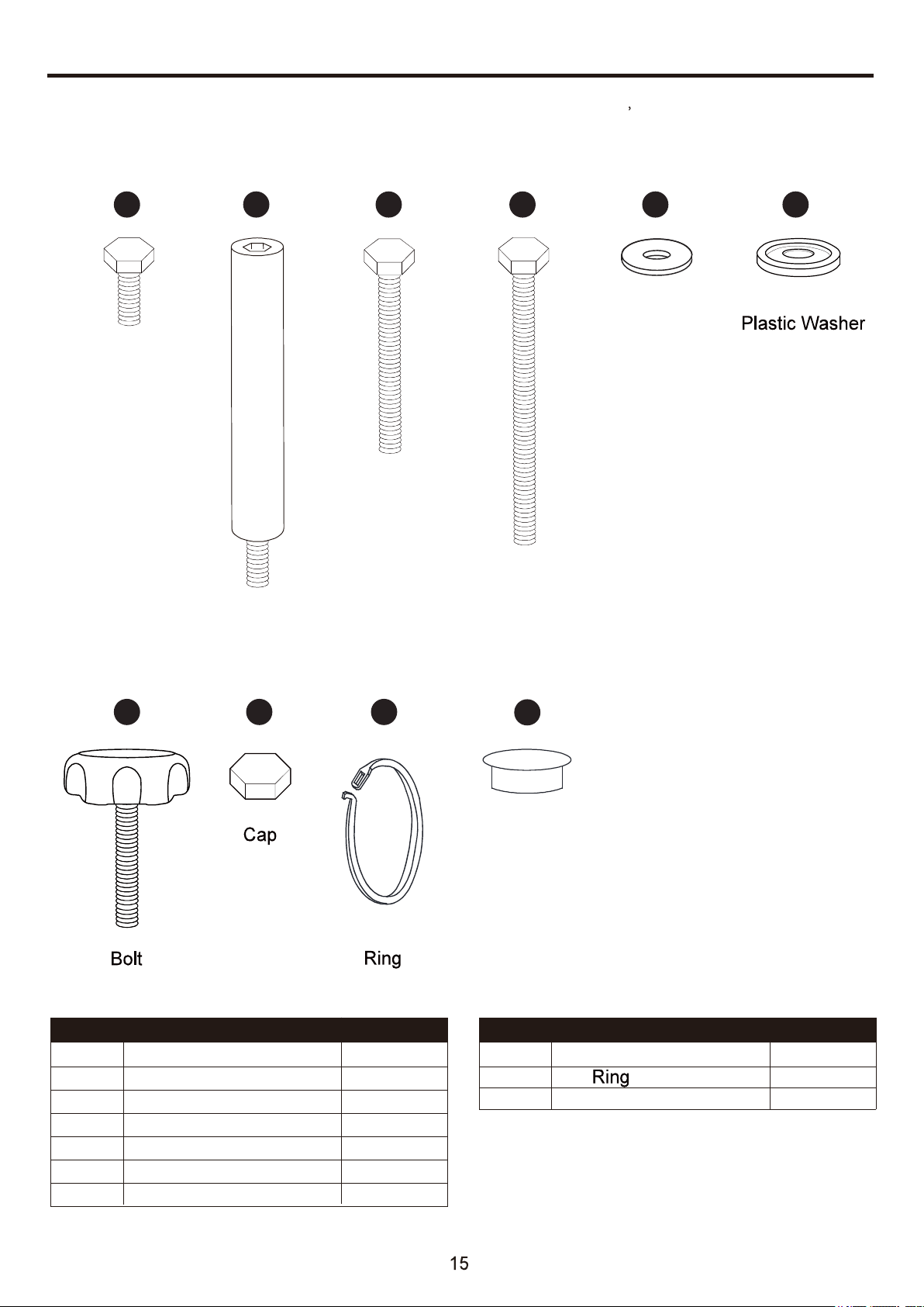
REPLACEMENT PARTS LIST
For replacement parts, call our customer service department at 1-866-439-9800 8 a.m. - 8 p.m.,
EST, Monday - Sunday. You could also contact us at [email protected] or
visit www.lowespartsplus.com.
PART DESCRIPTION PART #
AA 6
BB 2
CC 2
DD 2
EE 6
FF 6
GG 1
HH 6
PART DESCRIPTION PART #
II
MM
2
1
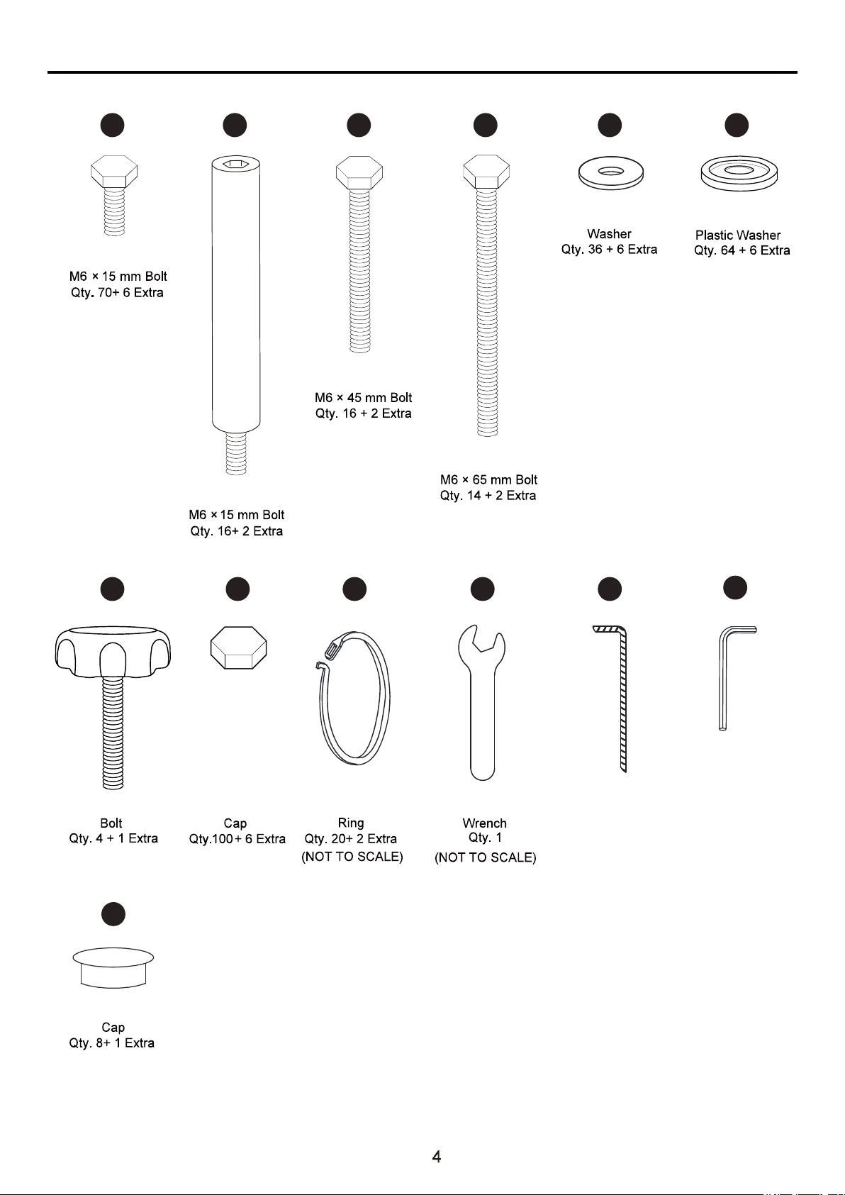
M6 x 15 mm Bolt
M6 x 15 mm Bolt
M6 x 15 mm Bolt
M6 x 15 mm Bolt
M6 x 45 mm Bolt
M6 x 65 mm Bolt
Washer
Plastic Washer
Bolt
Cap
Cap
M6 × 45 mm Bolt
Washer
AA CC
GG
BB DD EE
II
M6 × 65 mm Bolt
HH
Cap
MM
FF
Printed in China
¿Preguntas, problemas, piezas faltantes? Antes de volver a la tienda, llame a nuestro
Departamento de Servicio al Cliente al 1-866-439-9800, de lunes a domingo de 8 a.m.
a 8 p.m., hora estándar del Este. También puede ponerse en contacto con nosotros en
[email protected] o visitar www.lowespartsplus.com.
ALLEN + ROTH y el diseño del logo son marcas
comerciales o marcas registradas de LF, LLC.
Todos los derechos reservados.
17
ÍNDICE
Poste
Poste
Viga de arco
Viga de arco
Viga
Viga
Conector
Conector
Conector de arco
Casquillo
Casquillo
A1
A2
B1
B2
C1
C2
E1
E2
D
F1
F22
2
2
2
2
2
Viga superior
D1
14
2
2
18
7
4
7
Barra de soporte
Barra de soporte
Cubierta de la base
Base
Varilla de la pared lateral
Pared lateral
Toldo
4
4
4
2
2
2
1
G1
G
H
I
J
K
L
M1
M2
F1
K
A1
L
A1
B1
F1
C1
B2
A2
G
A2
C2
D1
D1
E1
E2
D
F2
G1
G
H
I
M1
M2
J
Varilla de sujeción del
toldo
Varilla de sujeción del
toldo
4
4
G1
CONTENIDO DEL PAQUETE
PIEZA DESCRIPCIÓN
CANTIDAD
PIEZA DESCRIPCIÓN
CANTIDAD
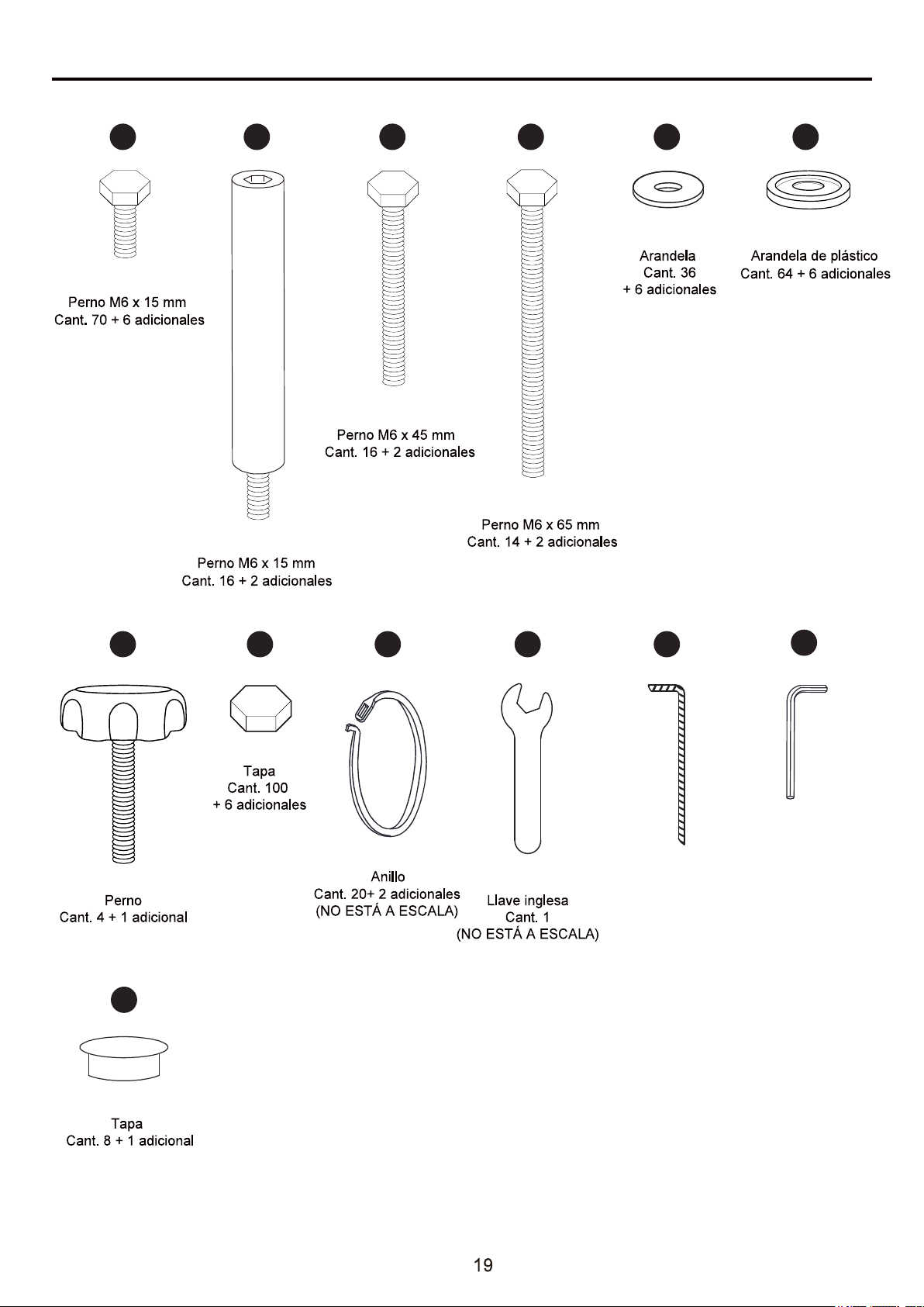
Llave Allen
Cant. 1
(NO ESTÁ A ESCALA)
AA CC
GG
BB DD EE
JJ KKII
Estaca
Cant. 16
(NO ESTÁ A ESCALA)
LL
ADITAMENTOS (se muestran en tamaño real)
HH
MM
FF

MANTENGA LA TELA DE ESTE GAZEBO ALEJADA DE LAS LLAMAS Y EL CALOR.
Lea y comprenda completamente este manual antes de intentar ensamblar o instalar el producto.
Para realizar el ensamblaje se necesitan tres personas.
INFORMACIÓN DE SEGURIDAD
ADVERTENCIA:
PRECAUCIÓN
PREPARACIÓN
Este gazebo cumple con los requisitos de inflamabilidad de la norma CPAI-84. La tela puede
quemarse si se encuentra en contacto continuo con cualquier fuente de llamas. La aplicación
de cualquier sustancia extraña a la tela del gazebo puede hacer que sus propiedades
ignífugas se anulen.
No lo deje afuera si hay vientos fuertes, lluvia torrencial o nieve. Si hay vientos fuertes, lluvia
torrencial o nieve, retire el toldo y la pared lateral, elimine la carga de nieve del techo y revise
si hay daños antes de continuar el uso.
Antes de comenzar a ensamblar el producto, asegúrese de tener todas las piezas. Compare las
piezas con la lista del contenido del paquete y la lista de aditamentos. No intente ensamblar el
producto si falta alguna pieza o si estas están dañadas.
Tiempo estimado de ensamblaje: 50 minutos
Herramientas necesarias para el ensamblaje (se incluyen): llave inglesa.
Herramientas necesarias para el ensamblaje (no se incluyen): gafas de seguridad, guantes, casco,
escalera de tijera.
Gafas de seguridad
Guantes
Escalera de tijera
Casco
A1
A1
A2
A2
A1
H
I
AA
HH
AA
HH
EE
EE
A2
1
AA
EE
JJ
HH
H
B1
B2
B2
B1
C1
C2
C1
C2
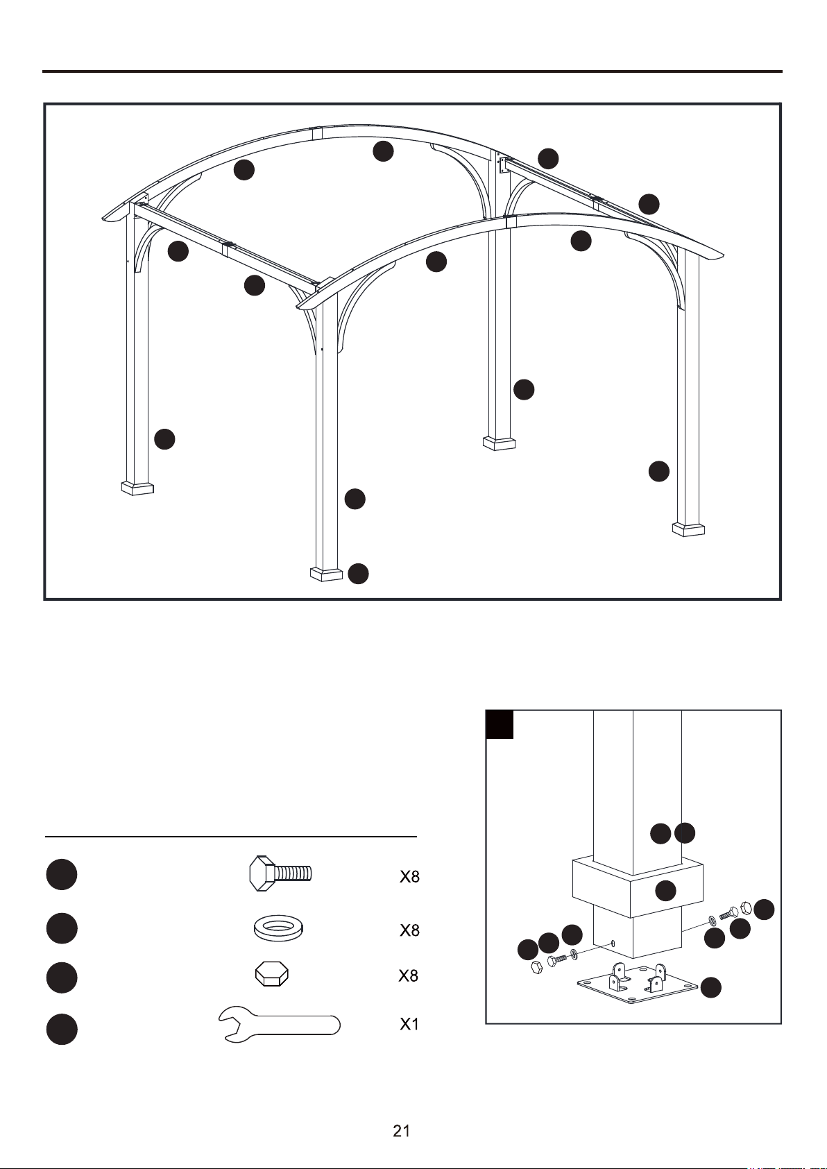
INSTRUCCIONES DE ENSAMBLAJE
1. Inserte los postes (A1/A2) en la cubierta de la
base (H), luego fije las bases (I) a los postes (A1/A2)
con pernos (AA) y arandelas (EE). Apriete con la
llave inglesa (JJ). Coloque la tapa (HH) sobre las
cabezas de los pernos.
Aditamentos utilizados
Perno M6 x 15 mm
Arandela
Tapa
Llave inglesa
INSTRUCCIONES DE ENSAMBLAJE
Aditamentos utilizados
Aditamentos utilizados
AA
FF
HH
JJ
AA
JJ
HH
FF
AA
FF
HH
C1
C1
C2
C1
F1
F1
2
4
3
E1
E1
AA
FF
HH
C2
C1
F1
AA
FF
HH
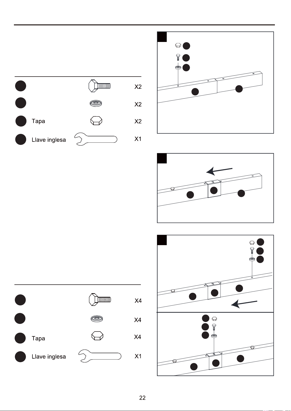
2. Inserte los conectores (E1) en las vigas (C1),
asegure con los pernos (AA) y las arandelas de
plástico (FF). Apriete con la llave inglesa (JJ).
Coloque la tapa (HH) sobre las cabezas de
los pernos.
3. Fije el casquillo (F1) a los ensamblajes
de las vigas (C1/E1).
4. Fije las vigas (C2) a los ensamblajes de las
vigas (C1/E1/F1) y asegure con los pernos (AA)
y las arandelas de plástico (FF). Apriete con la
llave inglesa (JJ). Coloque la tapa (HH) sobre
las cabezas de los pernos.
Perno M6 x 15 mm
Perno M6 x 15 mm
Arandela de plástico
Arandela de plástico
Aditamentos utilizados
AA
JJ
7
6
B1
E2
E2
F1
B1
FF
HH
AA
FF
HH
AA
FF
HH
Aditamentos utilizados
AA
JJ
FF
HH
5
AA
FF
F1
HH
AA
FF
HH
C1
J
J
C2
C2
J
INSTRUCCIONES DE ENSAMBLAJE
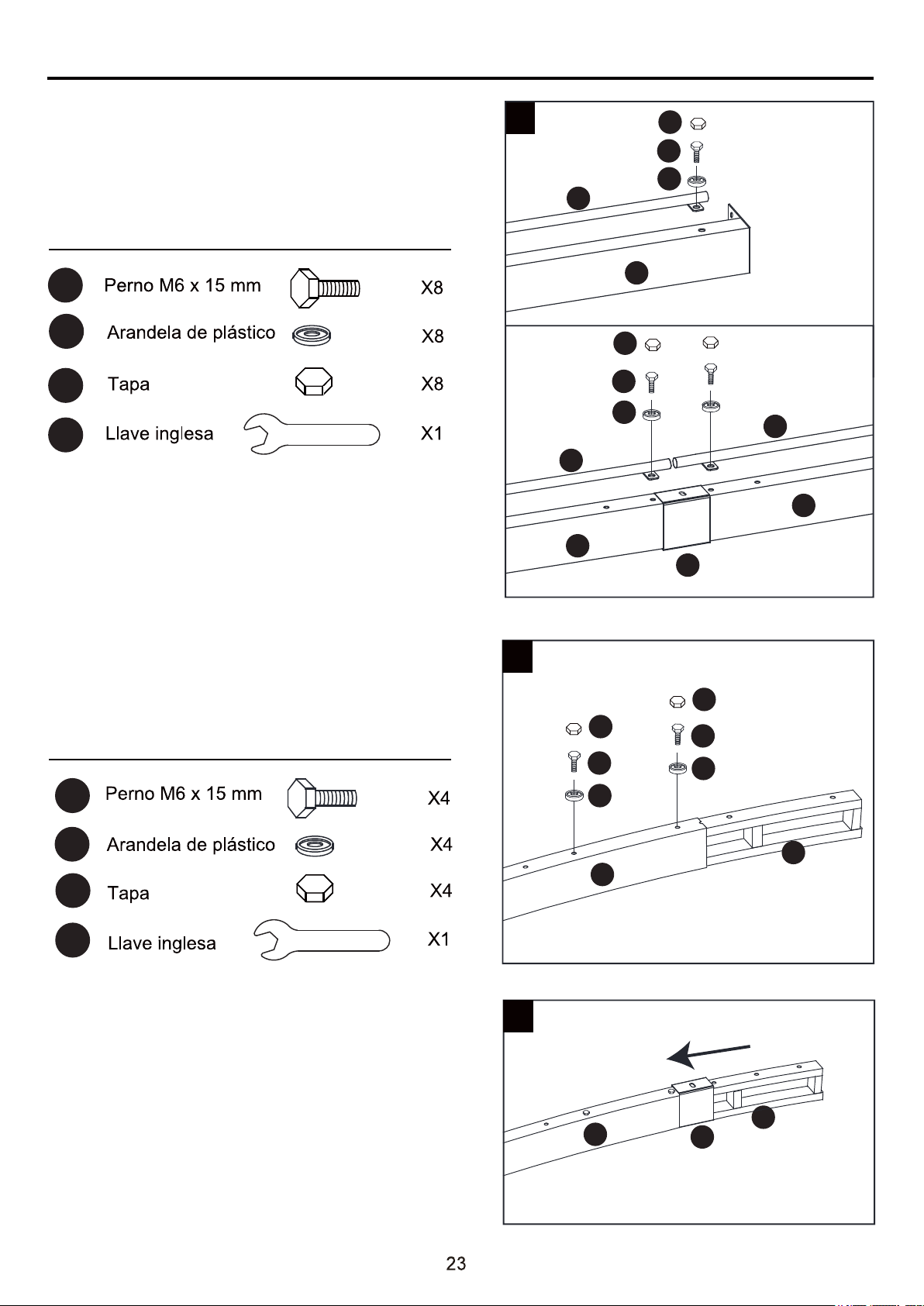
5. Fije la varilla de la pared lateral (J) a la
viga (C1/C2), asegure con los pernos (AA) y las
arandelas de plástico (FF). Apriete con la llave
inglesa (JJ). Coloque la tapa (HH) sobre las
cabezas de los pernos.
6. Inserte los conectores de arco (E2) en las vigas
de arco (B1), asegure con los pernos (AA) y las
arandelas de plástico (FF). Apriete con la llave
inglesa (JJ). Coloque la tapa (HH) sobre las
cabezas de los pernos.
7. Fije el casquillo (F1) a los ensamblajes de las
vigas (B1/E2).

INSTRUCCIONES DE ENSAMBLAJE
Aditamentos utilizados
Aditamentos utilizados
Aditamentos utilizados
AA
JJ
BB
LL
EE
HH
AA
JJ
FF
HH
F1
LL
BB
BB
B1
B2
A1
A2
A1
B1
B2
A2
A2
B2
A1
B1 B2
8
9
AA
FF
HH
AA
FF
HH
10
AA
EE
HH
LL
A1
A2
B1
B2
C2
C1
B1
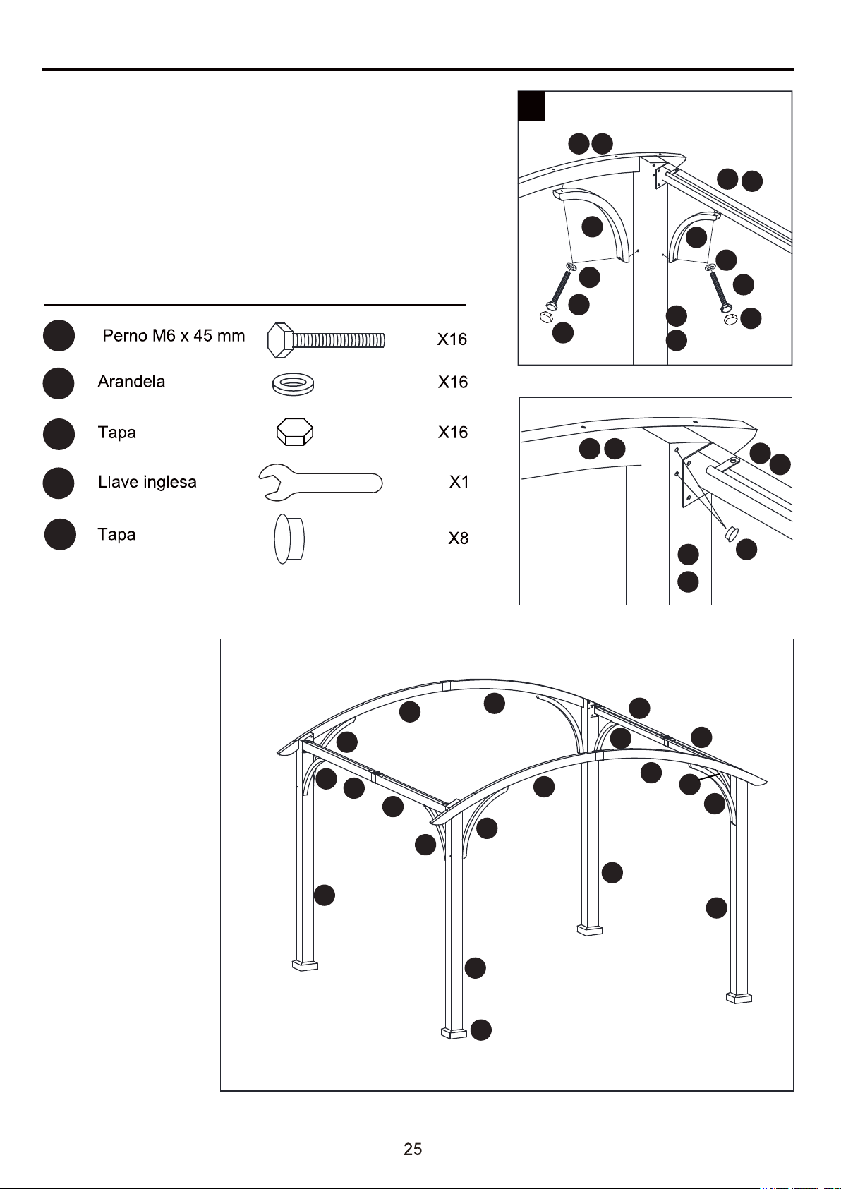
Fije las vigas de arco (B2) a los ensamblajes de
las vigas de arco (B1/E2/F1) y asegure con los
pernos (AA) y las arandelas de plástico (FF).
Apriete con la llave inglesa (JJ). Coloque la tapa
(HH) sobre las cabezas de los pernos.
Conecte el arco (B1/B2), que ya anteriormente
ha montado, a los postes (A1/A2) con los tornillos
(BB) a través de los agujeros que hay en los
mismos. Utilice una superficie plana y no abrasiva.
Apriete todos los tornillos con la llave
hexagonal (LL).
Levante la estructura de los postes (A1/A2) y
los arcos (B1/B2) con el apoyo de dos personas.
Fije las vigas (C1/C2) a los postes (A1/A2),
asegure con los pernos (AA) y las arandelas
(EE). Apriete con la llave inglesa (JJ). Coloque
la tapa (HH) sobre las cabezas de los pernos.
INSTRUCCIONES DE ENSAMBLAJE
MM
HH
Aditamentos utilizados
las vigas (C1/C2) con los pernos (CC) y las arandelas
(EE). Apriete con la llave inglesa (JJ). Repita este paso
para fijar la barra de soporte (G1) a los postes (A1/A2) y
las vigas de arco (B1/B2) con los pernos (CC) y las
arandelas (EE). Apriete con la llave inglesa (JJ).
Coloque la tapa (HH) sobre las cabezas de los pernos.
Coloque la tapa (MM) dentro de los postes (A1/A2).
11. Fije la barra de soporte (G) a los postes (A1/A2) y
CC
EE
JJ
11
EE
EE
HH
HH
CC
CC
A1
A2
B1 B2
C2
C1
G2
G1
G
MM
A1
A2
C1
C2
B1 B2
A1
A1
A2
A2
H
G1
C1
C2
C1
C2
G
G
B2
B1
G
G
G1
G1
B1
B2
A1

INSTRUCCIONES DE ENSAMBLAJE
Aditamentos utilizados
12. Inserte los conectores (D) en las vigas superiores
(D1), asegúrelos con pernos (AA) y arandelas de
plástico (FF). Fije el casquillo (F2) y las vigas
superiores (D1) a los ensambles de las vigas
(D1/D) y asegure con pernos (AA) y arandelas de
plástico (FF). Apriete con la llave inglesa (JJ).
Coloque la tapa (HH) sobre las cabezas de los
pernos.
AA
JJ
HH
FF
12
D1
D1
F2
D1
F2
D
D
D1
AA
FF
HH
A1
A1
K
D
A2
A2
D1
D1
F2
HH
AA
FF

INSTRUCCIONES DE ENSAMBLAJE
Aditamentos utilizados
13. Fije las vigas superiores ensambladas (D1)
a las vigas de arco (B1/B2) con los pernos (DD)
y las arandelas de plástico (FF). Apriete con la
llave inglesa (JJ). Coloque la tapa (HH) sobre
las cabezas de los pernos.
Nota: no fije las vigas superiores ensambladas
(D1) en los orificios afuera de las vigas de
arco (B1/B2).
13
B1
B2
DD
FF
HH
D1
HH
DD
JJ
FF
D1
D1
D1
INSTRUCCIONES DE ENSAMBLAJE
Aditamentos utilizados
Aditamentos utilizados
Aditamentos utilizados
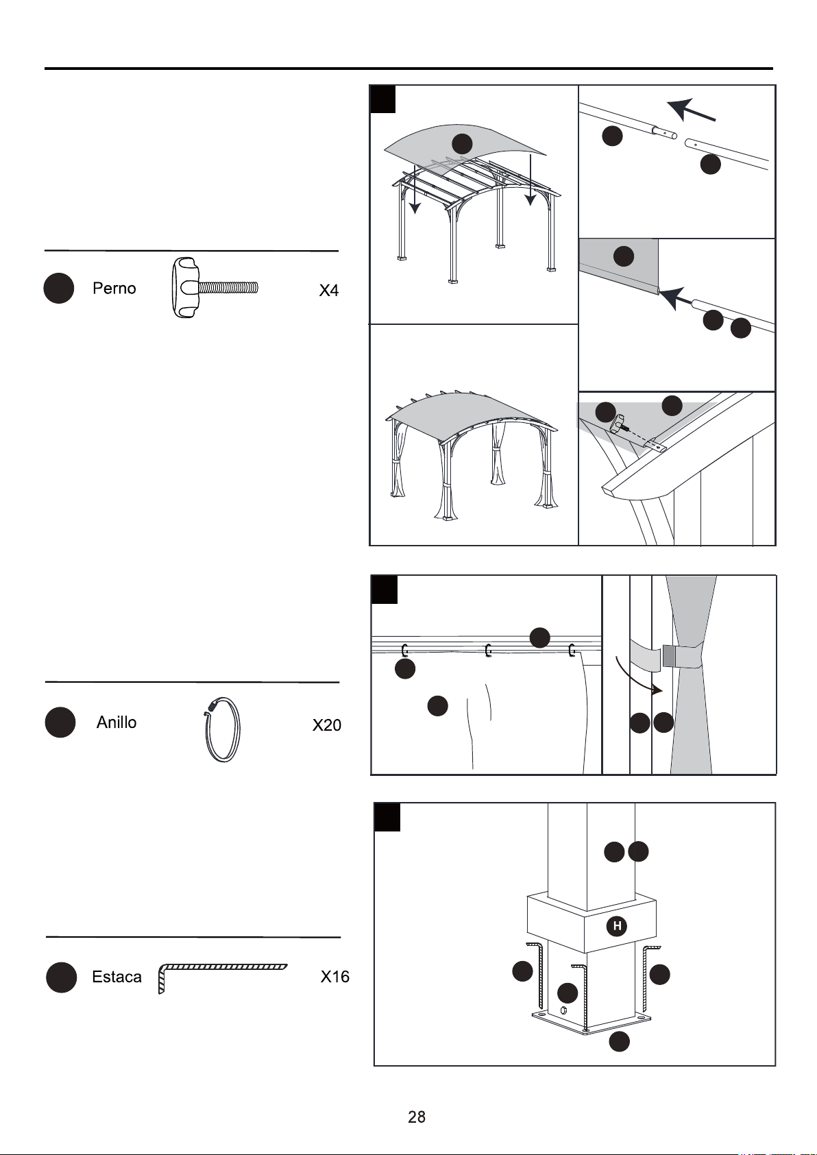
16. Levante las cubiertas de la base (H)
y asegure la pérgola ensamblada en
el suelo con las estacas (KK).
La pérgola ya está completamente
ensamblada.
A1
KK
KK
I
A2
16
15
KK
KK
14. Conecte la varilla de sujeción del
toldo (M1) y la varilla de sujeción del
toldo (M2), inserte la varilla de sujeción
del toldo ensamblada (M1/M2) en el
toldo (K) y, luego, fije la varilla en la
viga de arco (B1/B2) con un perno
(GG).
15. Coloque la pared lateral (L) en la
varilla de la pared lateral (J) a través
de los anillos (II) y, luego, fíjela en los
postes (A1/A2).
GG
II
A1
A2
14
K
L
J
II
M1
M2
K
M1
M2
K
GG

CUIDADO Y MANTENIMIENTO
GARANTÍA
1 AÑO DE GARANTÍA PARA LA ESTRUCTURA Y LA TELA.
LO QUE CUBRE LA GARANTÍA
Ofrecemos una garantía de 1 año por la compra original para la estructura y la tela desde la fecha de
compra, estas se reemplazarán sin costo debido a defectos de fabricación.
LO QUE NO CUBRE LA GARANTÍA
No realizamos reembolsos por los costos de transporte. Esta garantía no cubre daños provocados
por el uso comercial, los desastres naturales, los incendios, el congelamiento ni el abuso del producto.
La decoloración o el desteñido en el acabado o las telas como resultado de la exposición a productos
químicos o derrames no están cubiertos.
Póngase en contacto con el equipo de Servicio al Cliente al 1-866-439-9800.
Para limpiar, use una solución de detergente suave, enjuáguela con agua y deje que se seque al aire.
No use acetona, productos abrasivos u otros detergentes especiales porque dañarían el acabado
del producto.
Debido a la naturaleza del acero, puede oxidarse la superficie si este recubrimiento protector se raya.
Este es un proceso natural. Para minimizar este problema, se recomienda que tenga cuidado cuando
ensamble y manipule el producto para evitar que la pintura se raye.
LISTA DE PIEZAS DE REPUESTO
Para obtener piezas de repuesto, llame a nuestro Departamento de Servicio al Cliente al 1-866-439-9800,
de lunes a domingo de 8 a.m. a 8 p.m., hora estándar del Este. También puede ponerse en contacto
con nosotros en partsplus@lowes.com o visitar www.lowespartsplus.com.
PIEZA DESCRIPCIÓN PIEZA #
AA 6
BB 2
CC 2
DD 2
EE 6
FF 6
GG 1
HH 6
II
MM
2
1
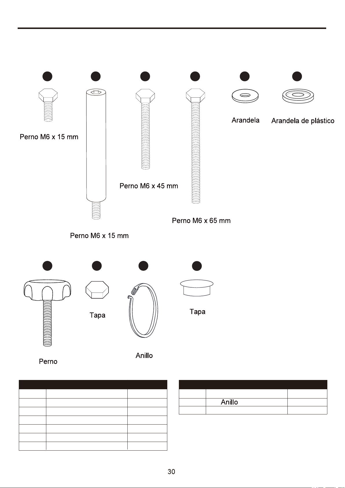
Perno M6 x 15 mm
Perno M6 x 15 mm
Perno M6 x 45 mm
Perno M6 x 65 mm
Arandela
Arandela de plástico
Perno
Tapa
Tapa
AA CC
GG
BB DD EE
IIHH
MM
FF
Impreso en China
PIEZA DESCRIPCIÓN PIEZA #
