Loading ...
Loading ...
Loading ...
5 English
Regarding drainage of drain pipe
Is the drain pipe executed to perform com-•
plete drainage?
If proper drainage is not carried out from the
outdoor drain pipes during air-conditioning op-
eration, chances are that dust and dirt are
clogged in the pipe. This may result in a water
leakage from the indoor unit. Under such circum-
stances, stop the operation of the air conditioner,
and then consult your dealer or our service sta-
tion.
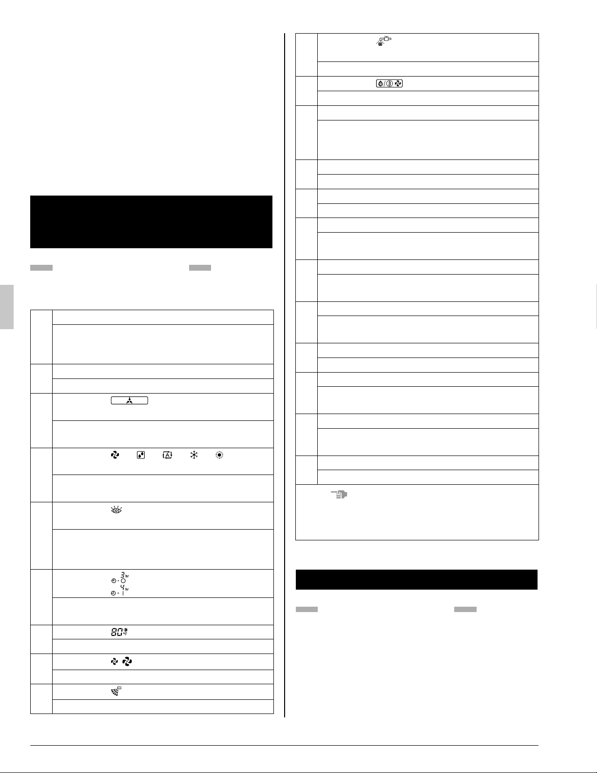
NAME AND FUNCTION OF 5.
EACH SWITCH AND DISPLAY
ON THE REMOTE CONTROLLER
Refer to Fig. 1 on page [1]
The illustrations in this operating manual corre-
spond to the remote control format BRC1C type.
1
ON/OFF BUTTON
Press the button and the system will start.
Press the button again and the system will
stop.
2
OPERATION LAMP (RED)
The lamp lights up during operation.
3
DISPLAY “
” (UNDER CENTRAL-
IZED CONTROL)
When this display shows, the system is UN-
DER CENTRALIZED CONTROL.
4
DISPLAY “
” “ ” “ ” “ ” “ ”
(OPERATION MODE)
This display shows the current OPERATION
MODE.
5
DISPLAY “
TEST ” (INSPECTION/TEST
OPERATION)
When the INSPECTION/TEST OPERATION
BUTTON is pressed, the display shows the
system mode is in.
6
DISPLAY “
” (PROGRAMMED TIME)
This display shows the PROGRAMMED
TIME of the system start or stop.
7
DISPLAY “
” (SET TEMPERATURE)
This display shows the set temperature.
8
DISPLAY “
” (FAN SPEED)
This display shows the set fan speed.
9
DISPLAY “
” (AIR FLOW FLAP)
Refer to “AIR FLOW DIRECTION ADJUST”.
10
DISPLAY “
” (TIME TO CLEAN AIR
FILTER)
Refer to “HOW TO CLEAN THE AIR FILTER”.
11
DISPLAY “
” (DEFROST)
Refer to “DEFROST OPERATION”.
12
NON-FUNCTIONING DISPLAY
If that particular function is not available,
pressing the button may display the words
“NOT AVAILABLE” for a few seconds.
13
TIMER MODE START/STOP BUTTON
Refer to “PROGRAM TIMER OPERATION”.
14
TIMER ON/OFF BUTTON
Refer to “PROGRAM TIMER OPERATION”.
15
INSPECTION/TEST OPERATION BUTTON
This button is used only by qualifi ed service
persons for maintenance purposes.
16
PROGRAMMING TIME BUTTON
Use this button for programming “START
and/or STOP” time.
17
TEMPERATURE SETTING BUTTON
Use this button for SETTING TEMPERA-
TURE.
18
FILTER SIGN RESET BUTTON
Refer to “HOW TO CLEAN THE AIR FILTER”.
19
FAN SPEED CONTROL BUTTON
Press this button to select the fan speed,
HIGH or LOW, of your choice.
20
OPERATION MODE SELECTOR BUTTON
Press this button to select OPERATION
MODE.
21
AIR FLOW DIRECTION ADJUST BUTTON
Refer to “AIR FLOW DIRECTION ADJUST”.
NOTE
For the sake of explanation, all indications are •
shown on the display in Fig. 1 on page [1] con-
trary to actual running situations.
OPERATION PROCEDURE6.
Refer to Fig. 1 on page [1]
To protect the unit, turn on the main power •
switch 6 hours before operation.
If the main power supply is turned off during •
operation, operation will restart automatically
after the power turns back on again.
01_EN_3PN07753-11N.indd 501_EN_3PN07753-11N.indd 5 12/19/2008 8:00:30 PM12/19/2008 8:00:30 PM
Loading ...
Loading ...
Loading ...