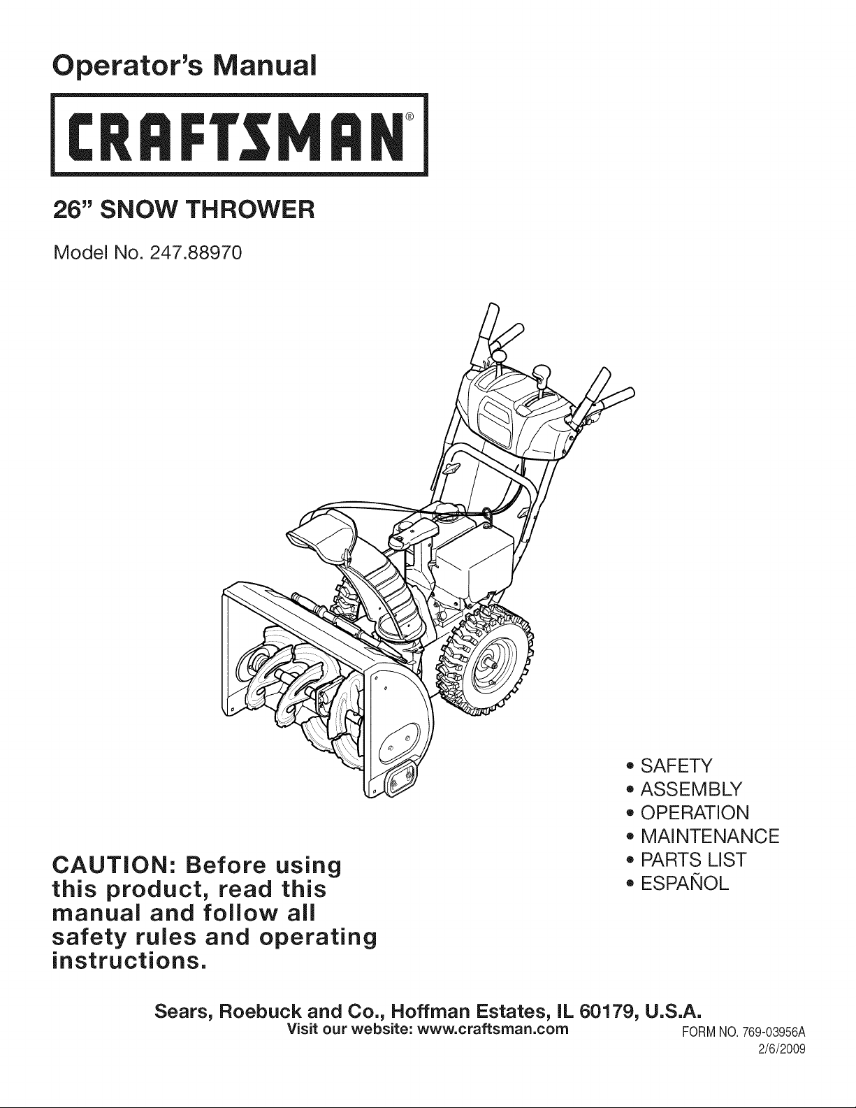
Operator's Manual
CRRFTSMRH
26" SNOW THROWER
Model No. 247.88970
CAUTION: Before using
this product, read this
manual and follow all
safety rules and operating
instructions.
o SAFETY
ASSEMBLY
OPERATION
MAINTENANCE
PARTS LIST
o ESPANOL
Sears, Roebuck and Co., Hoffman Estates, IL 60179, U.S.A.
Visit our website: www.craftsman.com FORM1/0. 769-03956A
2/6/2009
WarrantyStatement.................... Page2
SafeOperationPractices.............. Pages3-6
SafetyLabels......................... Page7
Assembly......................... Pages8-11
Operation........................ Pages12-15
Service&Maintenance.............. Pages16-23
Off-SeasonStorage................... Page24
Troubleshooting...................... Page25
PartsList......................... Pages26-35
RepairProtectionAgreement............ Page39
Espadol............................. Page40
CRAFTSMANLiMiTED WARRANTY
Two Years on Snow Thrower
Whenoperatedand maintainedaccordingto allsuppliedinstructions,if this snowthrowerfailsdue to a defectin materialor workmanshipwithin
twoyearsfromthe dateor purchase,returnit to any authorizedCraftsmandrop-off locationfor free repair. Forthe nearestauthorizedlocation,
call 1-800-4MYHOME.
Thiswarrantyappliesfor only90 daysfromthe dateof purchaseif thissnowthroweris everusedfor commercialor rentalpurposes.
Thiswarranty coversONLYdefects in material andworkmanship. Sears will NOTpay for:
• Expendableitemsthatbecomewornduringnormaluse,includingbutnot limitedto skidshoes,shaveplate,shearpins,sparkplug,air
cleaner,belts,andoil filter.
• Standardmaintenanceservicing,oilchanges,or tune-ups.
• Tire replacementor repaircausedby puncturesfrom outsideobjects,such as nails,thorns,stumps,or glass.
• Tireor wheelreplacementor repairresultingfromnormalwear,accident,orimproperoperationor maintenance.
• Repairsnecessarybecauseof operatorabuse, includingbutnot limitedto damagecausedby impactingobjectsthat bendthe frameor
crankshaft,orover-speedingtheengine.
• Repairsnecessarybecauseof operatornegligence,includingbut not limitedto,electricalandmechanicaldamagecausedby improper
storage,failureto usethe propergradeandamountof engineoil, or failureto maintainthe equipmentaccordingto the instructionscontained
inthe operator'smanual.
• Engine(fuelsystem)cleaningor repairscausedbyfuel determinedto becontaminatedoroxidized(stale).In general,fuel shouldbeused
within30 daysof itspurchasedate.
• Normaldeteriorationandwearof the exteriorfinishes,or productlabelreplacement.
Thiswarrantyappliesonly whilethisproductis usedinthe UnitedStates.
Thiswarrantygivesyou specificlegalrights,andyou mayalso haveotherrightswhichvaryfromstateto state.
Sears, Roebuck and Co., NoffmanEstates, IL 60179
EngineOilType: 5W-30
EngineOilCapacity: 20ounces
FuelCapacity: 2.3Quarts
SparkPlug: TorchF6RTC(F6TC)
SparkPlugGap: .020"to .030"
Model Number.................................................................
Serial Number .................................................................
Dateof Purchase.............................................................
Recordthe modelnumber,serialnumber
anddateof purchaseabove
© Sears Brands,LLC
2
Thissymbolpointsout importantsafetyinstructionswhich,if not
followed,couldendangerthepersonalsafetyand/orpropertyof
yourselfandothers. Readandfollowall instructionsin thismanual
beforeattemptingto operatethismachine.Failureto complywith
theseinstructionsmay resultin personalinjury.Whenyou seethis
symbol,HEEDITSWARNING!
CALIFORNIA PROPOSITION 65
EngineExhaust,someof itsconstituents,and certainvehicle
componentscontainoremitchemicalsknownto Stateof California
to cause cancerandbirthdefectsorotherreproductiveharm,
Thismachinewasbuiltto be operatedaccordingto the safeopera-
tion practicesin this manual.As withanytypeof powerequipment,
carelessnessor error on the partof the operatorcan resultin serious
injury.Thismachineis capableof amputatingfingers,hands,toes
andfeetandthrowingdebris.Failureto observethe followingsafety
instructionscouldresultin seriousinjuryor death.
Your Responsibility--Restrict the useof this powermachineto
personswho read,understandandfollowthewarningsand instruc-
tionsin thismanualandon the machine,
SAVE THESE INSTRUCTIONS!
TRAiNiNG
• Read,understand,and followall instructionson the machineand
in themanual(s)beforeattemptingto assembleandoperate.
Failureto do socan resultin seriousinjuryto the operatorand/
orbystanders.Keepthismanualin a safeplaceforfutureand
regularreferenceandfor orderingreplacementparts. Forques-
tionscall,1-800-659-5917.
• Befamiliarwithall controlsandtheir properoperation.Knowhow
to stop the machineanddisengagethemquickly.
• Neverallowchildrenunder14yearsof ageto operatethis
machine.Children14andover shouldreadandunderstandthe
instructionsand safe operationpracticesin this manualand on
the machineand be trainedandsupervisedby an adult.
• Neverallowadultsto operatethis machinewithoutproper
instruction.
• Thrownobjectscan causeseriouspersonalinjury.Planyour
snow-throwingpatternto avoiddischargeof materialtoward
roads,bystandersandthe like.
• Keepbystanders,pets and childrenat least75feetfromthe
machinewhile itisin operation.Stopmachineifanyoneenters
the area.
• Exercisecautionto avoidslippingor falling,especiallywhen
operatinginreverse.
PREPARATION
Thoroughlyinspecttheareawherethe equipmentis to beused.
Removeall doormats,newspapers,sleds,boards,wires and other
foreignobjects,whichcouldbe trippedoverorthrownby the auger/
impeller.
Alwayswear safetyglassesor eyeshieldsduringoperationand
while performingan adjustmentor repairto protectyoureyes.
Thrownobjectswhichricochetcancauseseriousinjuryto the
eyes.
Donot operatewithoutwearingadequatewinteroutergarments.
Donot wearjewelry,long scarvesor otherlooseclothing,which
could becomeentangledin movingparts.Wearfootwearwhich
will improvefooting on slipperysurfaces.
Usea groundedthree-wireextensioncordand receptaclefor all
machineswith electricstartengines.
Disengageall controlleversbeforestartingthe engine.
Adjustcollectorhousingheightto cleargravelorcrushedrock
surfaces.
Neverattemptto make anyadjustmentswhileengineis running,
exceptwherespecificallyrecommendedinthe operator'smanual.
Letengineandmachineadjustto outdoortemperaturebefore
startingto clearsnow.
3
Safe Handling of Gasoline
Toavoidpersonalinjuryor propertydamageuseextremecare in
handlinggasoline.Gasolineis extremelyflammableandthe vaporsare
explosive.Seriouspersonalinjurycan occurwhengasolineis spilled
onyourselfor yourclotheswhichcan ignite.Washyour skin and
changeclothesimmediately.
• Useonly anapprovedgasolinecontainer.
• Extinguishall cigarettes,cigars,pipesand other sources
of ignition.
• Neverfuelmachineindoors.
• Neverremovegas capor addfuel whilethe engineis hot
or running.
• Allowengine to coolat leasttwo minutesbeforerefueling.
• Neveroverfill fueltank. Filltank to no morethan1/2inch
belowbottomof filler neckto providespacefor fuel
expansion.
• Replacegasolinecap andtightensecurely.
• If gasolineis spilled,wipeit offthe engineand equipment.
Movemachineto anotherarea.Wait5 minutesbefore
startingthe engine.
• Neverstorethe machineor fuel containerinsidewhere
thereis an open flame,sparkor pilotlight (e.g.furnace,
waterheater,spaceheater,clothesdryer etc.).
• Allowmachineto cool at least5 minutesbeforestoring.
• Neverfill containersinsidea vehicleor on a truckor trailer
bedwitha plasticliner.Alwaysplacecontainersonthe
groundawayfromyourvehiclebeforefilling.
• If possible,removegas-poweredequipmentfrom thetruck
ortrailerand refuelit on the ground.If thisis not possible,
then refuelsuchequipmentona trailerwitha portable
container,ratherthan fromagasolinedispensernozzle.
• Keepthe nozzleincontactwiththe rimof the fueltankor
containeropeningat all timesuntil fuelingis complete.Do
notuse a nozzlelock-opendevice.
OPERATION
• Do not puthandsorfeetnear rotatingparts,in the auger/impeller
housingor chuteassembly.Contactwith the rotatingpartscan
amputatehandsandfeet.
• Theauger/impellercontrolleveris a safetydevice.Neverbypass
itsoperation.Doingso makesthe machineunsafeand may cause
personalinjury.
• Thecontrolleversmustoperateeasilyin bothdirectionsand
automaticallyreturnto the disengagedpositionwhenreleased.
• Neveroperatewitha missingor damagedchuteassembly.Keep
all safetydevicesin placeandworking.
• Neverrunanengineindoorsor ina poorlyventilatedarea. Engine
exhaustcontainscarbonmonoxide,an odorlessanddeadlygas.
• Do notoperatemachinewhileunder the influenceof alcoholor
drugs.
• Mufflerandenginebecomehotandcan causea burn.Do not
touch.Keepchildrenaway.
• Exerciseextremecautionwhenoperatingon orcrossinggravel
surfaces.Stayalertfor hiddenhazardsor traffic.
• Exercisecautionwhenchangingdirectionandwhileoperatingon
slopes.
• Planyoursnow-throwingpatternto avoiddischargetowards
windows,walls,carsetc. Thus,avoidingpossibleproperty
damageor personalinjurycausedby a ricochet.
• Neverdirect dischargeat children,bystandersand petsor allow
anyoneinfrontof the machine.
• Donot overloadmachinecapacityby attemptingto clearsnowat
too fastof a rate.
• Neveroperatethis machinewithoutgoodvisibility or light. Always
be sureof yourfootingand keepa firm hold on the handles.Walk,
neverrun.
• Disengagepowerto theauger/impellerwhentransportingor not
in use.
• Neveroperatemachineat hightransportspeedson slippery
surfaces.Lookdownand behindand usecare whenbackingup.
• If the machineshouldstart to vibrateabnormally,stopthe engine,
disconnectthe spark plugwire andgroundit againstthe engine.
Inspectthoroughlyfor damage.Repairanydamagebefore
startingandoperating.
• Disengageall controlleversand stop enginebeforeyouleave
the operatingposition(behindthe handles).Wait untilthe auger/
impellercomesto a completestop beforeuncloggingthechute
assembly,makingany adjustments,or inspections.
• Neverput yourhandinthe dischargeor collectoropenings.Do
not unclogchuteassemblywhileengineis running.Shutoff
engineand remainbehindhandlesuntilall movingpartshave
stoppedbeforeunclogging.
• Useonly attachmentsandaccessoriesapprovedby the manufac-
turer (e.g.wheelweights,tire chains,cabsetc.).
• Whenstartingengine,pullcord slowlyuntilresistanceis felt, then
pull rapidly.Rapidretractionof startercord(kickback)will pull
handandarmtowardenginefasterthan youcan let go. Broken
bones,fractures,bruisesor sprainscould result.
• If situationsoccur whichare notcoveredin this manual,use care
andgoodjudgment.ContactCustomerSupportfor assistance
andthe nameof your nearestservicingdealer.
CLEARING A CLOGGED DISCHARGE CHUTE
Handcontactwiththe rotatingimpellerinsidethe dischargechute
is the mostcommoncauseof injuryassociatedwithsnowthrowers.
Neveruse yourhand to cleanout thedischargechute.
Toclear thechute:
1. SHUTTHEENGINEOFF!
2. Wait 10secondsto be surethe impellerbladeshavestopped
rotating.
3. Alwaysusea clean-outtool, not yourhands.
4
MAINTENANCE & STORAGE
• Nevertamperwithsafetydevices.Checktheirproperoperation
regularly.Referto the maintenanceandadjustmentsectionsof
thismanual.
• Beforecleaning,repairing,or inspectingmachinedisengageall
controlleversandstop the engine.Waituntilthe auger/impeller
cometo a completestop.Disconnectthe sparkplugwireand
groundagainsttheengineto preventunintendedstarting.
Checkboltsand screwsfor propertightnessat frequentintervals
to keepthe machineinsafe workingcondition.Also, visually
inspectmachinefor anydamage.
Do notchangetheenginegovernorsettingor over-speedthe
engine.Thegovernorcontrolsthe maximumsafeoperatingspeed
of the engine.
Snowthrowershaveplatesand skidshoesare subjectto wear
anddamage.Foryoursafetyprotection,frequentlycheckall
componentsand replacewithoriginalequipmentmanufacturer's
(OEM)partsonly."Useof parts whichdo not meetthe original
equipmentspecificationsmayleadto improperperformanceand
compromisesafety!"
Checkcontrolleversperiodicallyto verifythey engageanddisen-
gageproperlyand adjust,if necessary.Referto the adjustment
sectioninthisoperator'smanualfor instructions.
Maintainor replacesafetyandinstructionlabels,as necessary.
• Observeproperdisposallawsand regulationsfor gas,oil,etc. to
protectthe environment.
Priorto storing,runmachinea few minutestoclear snowfrom
machineand preventfreezeupof auger/impeller.
Neverstorethe machineorfuel containerinsidewherethereisan
openflame,spark or pilot lightsuchas a waterheater,furnace,
clothesdryer etc.
Alwaysreferto the operator'smanualfor properinstructionson
off-seasonstorage.
Checkfuelline,tank, cap,andfittingsfrequentlyfor cracksor
leaks.Replaceif necessary.
Do notcrank enginewithsparkplugremoved.
Accordingto the ConsumerProductsSafetyCommission(CPSC)
andthe U.S.EnvironmentalProtectionAgency(EPA),this product
hasan AverageUsefulLifeof seven(7) years,or 60 hoursof
operation.At the endof theAverageUsefulLifehavethe machine
inspectedannuallybyan authorizedservicedealer to ensurethat
allmechanicaland safetysystemsare workingproperlyand not
wornexcessively.Failureto do so can resultin accidents,injuries
ordeath.
DO NOT MODIFY ENGINE
Toavoidseriousinjuryor death,do not modifyengineinany way.
Tamperingwiththe governorsettingcanleadto a runawayengineand
causeit to operateat unsafespeeds.Nevertamperwithfactory setting
of engine governor.
NOTICE REGARDING EMISSIONS
Engineswhich are certifiedtocomplywith Californiaand federal
EPAemissionregulationsfor SORE(SmallOff RoadEquipment)are
certifiedto operateon regularunleadedgasoline,and mayinclude
the followingemissioncontrol systems:EngineModification(EM),
OxidizingCatalyst(OC),SecondaryAirInjection(SAI)and ThreeWay
Catalyst(TWO)if so equipped.
SPARK ARRESTOR
Thismachineisequippedwithan internalcombustionengineand
shouldnotbe usedonor nearany unimprovedforest-covered,
brush-coveredorgrass-coveredlandunlessthe engine'sexhaust
systemisequippedwitha sparkarrestermeetingapplicablelocalor
statelaws(if any)
Ifa sparkattesteris used,it shouldbe maintainedin effectiveworking
orderby theoperator.Inthe State of Californiathe aboveis required
bylaw (Section4442 of the CaliforniaPublicResourcesCode). Other
statesmayhavesimilarlaws. Federallawsapplyonfederallands.
A sparkarresterfor the muffleris availablethroughyournearestSears
PartsandRepairServiceCenter.
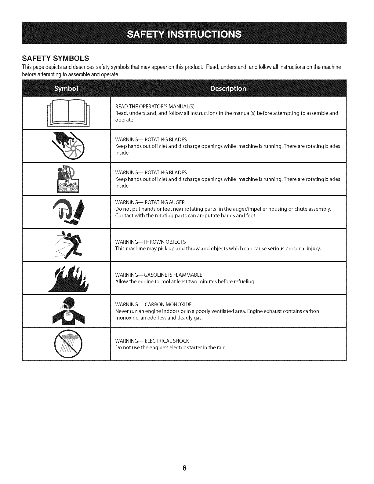
SAFETY SYMBOLS
Thispagedepictsanddescribessafetysymbolsthat mayappear on this product. Read,understand,andfollowall instructionson the machine
beforeattemptingto assembleandoperate.
i
i
READ THE OPERATOR'S MANUAL(S)
Read, understand, and follow all instructions in the manual(s) before attempting to assemble and
operate
WARNING-- ROTATING BLADES
Keep hands out of inlet and discharge openings while machine is running. There are rotating blades
inside
WARNING-- ROTATING BLADES
Keep hands out of inlet and discharge openings while machine is running. There are rotating blades
inside
WARNING-- ROTATING AUGER
Do not put hands or feet near rotating parts, in the auger/impeller housing or chute assembly.
Contact with the rotating parts can amputate hands and feet.
WARNING--THROWN OBJECTS
This machine may pick up and throw and objects which can cause serious personal injury.
WARNING--GASOLINE IS FLAMMABLE
Allow the engine to cool at least two minutes before refueling.
WARNING-- CARBON MONOXIDE
Never run an engine indoors or in a poorly ventilated area. Engine exhaust contains carbon
monoxide, an odorless and deadly gas.
WARNING-- ELECTRICAL SHOCK
Do not use the engine's electric starter in the rain
6
1.KEEPAWAYFROMROTATINGiMPELLER
ANDAUGER,CONTACTWiTHiMPELLEROR
AUGERCANAMPUTATEHANDSANDFEET.
2. USECLEAN-OUTTOOLTOUNCLOG
DISCHARGECHUTE.
3.DISENGAGECLUTCHLEVERS,STOPENGINE,
AND REMAINBEHINDHANDLESUNTILALL
MOVING PARTSHAVE STOPPEDBEFORE
UNCLOGGING OR SERViCiNGMACHINE.
TO AVOIDTHROWN OBJECTSiNJURiES,
NEVERDIRECTDISCHARGEATBYSTANDERS.
USEEXTRACAUTIONWHEN OPERATINGON
GRAVEL SURFACES.
5.BEAD OPERATOR'S MANUAL.
CLEAN-OUT TOOL
7
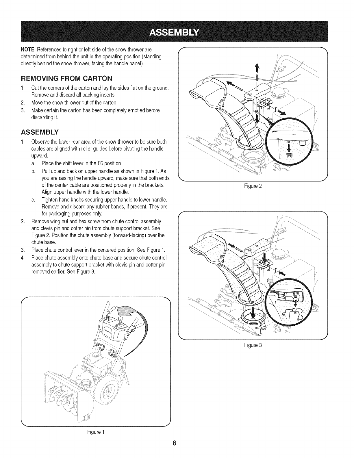
NOTE:Referencesto rightorleft sideof the snowthrowerare
determinedfrombehindthe unit in the operatingposition(standing
directlybehindthe snow thrower,facingthe handlepanel).
REMOVING FROM CARTON
1. Cut the cornersof thecarton and lay the sidesflaton the ground.
Removeand discard all packinginserts.
2. Movethe snowthrowerout of thecarton.
3. Makecertainthe cartonhas beencompletelyemptiedbefore
discardingit.
ASSEMBLY
1. Observethe lowerreararea of the snowthrowerto besure both
cablesarealignedwith rollerguidesbeforepivotingthe handle
upward.
a. Placethe shiftleverin the F6position.
b. Pull up and back on upperhandleas shownin Figure1.As
youare raisingthe handleupward,make surethat bothends
of the centercablearepositionedproperlyin the brackets.
Alignupperhandlewith the lowerhandle.
c. Tightenhandknobs securingupper handleto lowerhandle.
Removeand discard any rubberbands,if present.Theyare
for packagingpurposesonly.
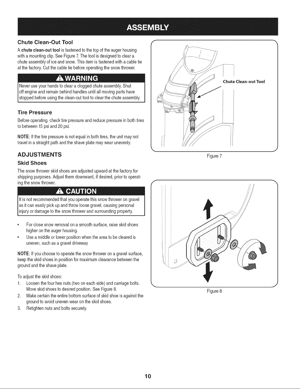
2. Removewingnut andhexscrewfromchutecontrolassembly
andclevispinandcotter pinfromchutesupportbracket.See
Figure2. Positionthe chuteassembly(forward-facing)overthe
chutebase.
3. Placechutecontrol leverin the centeredposition.SeeFigure1.
4. Placechuteassemblyontochutebaseand securechute control
assemblyto chute supportbracketwithclevispinand cotterpin
removedearlier.See Figure3.
Figure2
Figure3
Figure1
J
8
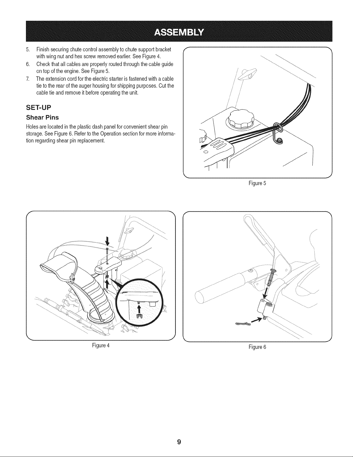
5. Finish securingchutecontrolassemblyto chutesupportbracket
withwingnut and hex screwremovedearlier.SeeFigure4.
6. Checkthat all cables are properlyroutedthroughthe cableguide
ontop of the engine.SeeFigure5.
7. The extensioncord forthe electricstarteris fastenedwitha cable
tie to the rear of the augerhousingfor shippingpurposes.Cut the
cabletie and removeit beforeoperatingthe unit.
SET-UP
Shear Pins
Holesare locatedinthe plasticdashpanelfor convenientshearpin
storage.See Figure6. Referto the Operationsectionfor moreinforma-
tion regardingshearpin replacement.
Figure5
f
Figure4
Figure6
9
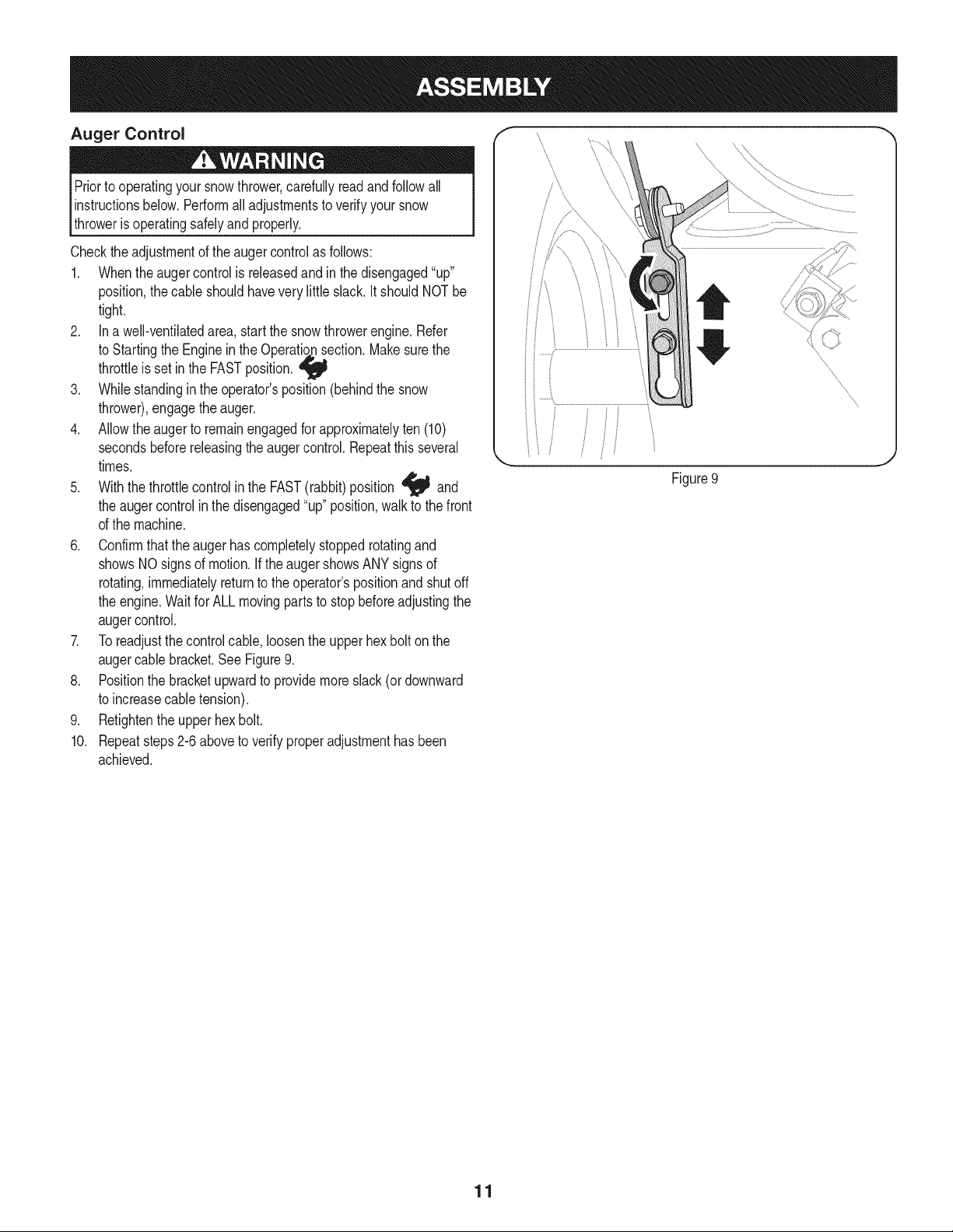
Chute Clean=Out Tool
A chute clean-out tool is fastenedto the topof the auger housing
witha mountingclip.SeeFigure7.The tool is designedto cleara
chuteassemblyof ice andsnow.This itemis fastenedwith acable tie
at the factory.Cutthe cabletie beforeoperatingthe snowthrower.
Ioff _1 .allmoving}oartshave
stoppedbeforeusingthe clean-outtool to clearthe chuteassembly.
Tire Pressure
Beforeoperating,checktire pressureandreducepressurein bothtires
to between15psi and20 psi.
NOTE:Ifthe tire pressureis not equalin both tires,the unitmay not
travelina straightpathandthe shaveplatemaywear unevenly.
ADJUSTMENTS
Skid Shoes
The snowthrowerskid shoesareadjustedupwardat the factoryfor
shippingpurposes.Adjustthemdownward,ifdesired,prior to operat-
ingthe snowthrower.
lit is not recommendedthat this thrower
you operate
snow on
gravel
as it can easilypickup and throw loosegravel,causingpersonal
injuryordamageto the snowthrowerandsurroundingproperty.
• Forclose snow removalon a smoothsurface,raiseskid shoes
higheronthe augerhousing.
• Usea middleor lowerpositionwhenthe areato be clearedis
uneven,suchasa graveldriveway
NOTE:Ifyouchooseto operatethe snowthrowerona gravelsurface,
keepthe skidshoesin positionfor maximumclearancebetweenthe
groundandthe shaveplate.
To adjustthe skidshoes:
1. Loosenthefour hex nuts(two on eachside)andcarriagebolts.
Moveskidshoesto desiredposition.SeeFigure8.
2. Makecertainthe entirebottomsurfaceof skid shoe is againstthe
groundto avoid unevenwearon the skid shoes.
3. Retightennutsandboltssecurely.
Figure7
Figure8
10
Auger Control
Priorto operatingyoursnowthrower,carefullyreadand followall
instructionsbelow.Performall adjustmentsto verifyyour snow
throweris operatingsafelyand properly.
Checktheadjustmentof the augercontrolas follows:
1. Whentheaugercontrolis releasedand in the disengaged"up"
position,the cableshouldhavevery littleslack.ItshouldNOTbe
tight.
2. In a well-ventilatedarea,start the snowthrowerengine.Refer
to Startingthe Enginein the Operati_ection. Makesurethe
throttleis set in the FASTposition.
3. Whilestandingin the operator'sposition(behindthe snow
thrower),engagethe auger.
4. Allowtheauger to remainengagedfor approximatelyten (10)
secondsbeforereleasingthe augercontrol.Repeatthis several
times.
5. With thethrottlecontrolin the FAST(rabbit)position _J_ and
the augercontrolin the disengaged"up"position,walk to thefront
of the machine.
6. Confirmthat the augerhas completelystoppedrotatingand
showsNOsignsof motion.If the augershowsANYsignsof
rotating,immediatelyreturnto the operator'spositionand shutoff
the engine.Waitfor ALL movingparts to stopbeforeadjustingthe
augercontrol.
7. Toreadjustthecontrolcable, loosentheupper hexbolt on the
augercablebracket.SeeFigure9.
8. Positionthe bracketupwardto providemoreslack(or downward
to increasecabletension).
9. Retightenthe upperhex bolt.
10. Repeatsteps2-6 aboveto verifyproperadjustmenthasbeen
achieved.
f
Figure9
J
11
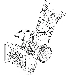
f
Drive Control
ShiftLever
J FourWayChuteControP
J j
J AugerControl
GasCap
\
ChuteAssembly
\
\\
CleanOut
Tool
'\\
\\
\
Augers
OUFUl
\\
\
Skid Shoe
Mumer Recoil Starter
Handle
Primer
Key
Throttle
Control
Choke
Control
Electric Start
Button
Oil Drain Electric
.. Starter Outlet ,j
Figure10
Nowthat youhavesetup yoursnowthrower,it's importantto become
acquaintedwith itscontrolsand features.Referto Figure10.
SHIFT LEVER 6
The shiftleveris locatedonthe rightsideof the handle panel. 5
Placethe shiftleverinto anyof eightpositionsto controlthe 4
directionof travel and groundspeed.
Forward 3
Yoursnowthrowerhas six forward(F) speeds.Positionone(1)is t 2
the slowestand positionsix (6) is the fastest. F 1
Reverse
Yoursnowthrowerhastwo reverse(R) speeds.One (1) is the
slowerandtwo (2) is the faster.
CHUTE ASSEMBLY
Snowdrawnintothe augerhousingis dischargedout the chute
assembly.
IGNITION KEY
The ignitionkeyis a safetydevice.It mustbe
fullyinsertedin orderfor the engineto start.
Removethe ignitionkeywhenthe snow thrower
is not in use.
NOTE: Donot turnthe ignitionkey inan attempt
to startthe engine.Doingso may causeit to
break.
CHOKE CONTROL
The chokecontrolis foundon the rearof the
engineand is activatedby rotatingthe knob
clockwise.Activatingthe choke controlcloses
the choke plateon thecarburetorandaids in
startingthe engine.
,J
Meets ANSi Safety Standards
CraftsmanSnowThrowersconformto the safetystandardof the AmericanNationalStandardsInstitute(ANSi).
12
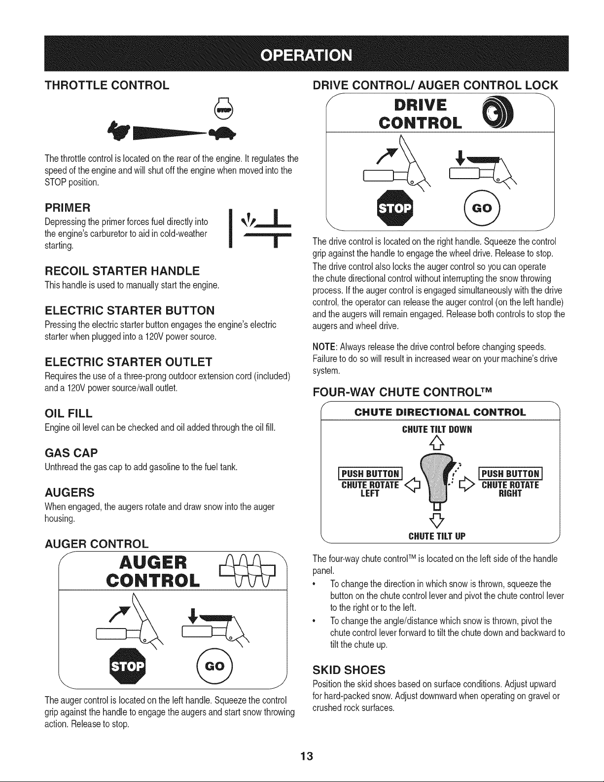
THROTTLE CONTROL
Thethrottlecontrolis locatedon the rearof the engine.It regulatesthe
speedof theengineandwill shutoff the enginewhenmovedintothe
STOPposition.
PRIMER
Depressingthe primerforcesfuel directlyinto
the engine'scarburetorto aid in cold-weather
starting.
RECOIL STARTER HANDLE
Thishandleis usedto manuallystartthe engine.
ELECTRIC STARTER BUTTON
Pressingthe electricstarterbuttonengagesthe engine'selectric
starterwhenpluggedintoa 120Vpowersource.
ELECTRIC STARTER OUTLET
Requiresthe useof a three-prongoutdoorextensioncord(included)
anda 120Vpowersource/walloutlet.
DRIVE CONTROL/AUGER CONTROL LOCK
DRIVE
CONTROL
The drivecontrolis locatedon the righthandle.Squeezethe control
gripagainstthe handleto engagethe wheeldrive.Releaseto stop.
The drivecontrolalso lockstheaugercontrolso youcan operate
the chute directionalcontrolwithoutinterruptingthe snowthrowing
process.If the augercontrolis engagedsimultaneouslywiththe drive
control,the operatorcan releasethe augercontrol (on the lefthandle)
andthe augerswill remainengaged.Releaseboth controlsto stop the
augersandwheeldrive.
NOTE:Alwaysreleasethedrivecontrol beforechangingspeeds.
Failureto do so will result in increasedwearon yourmachine'sdrive
system.
FOUR=WAY CHUTE CONTROL TM
OIL FILL
Engineoil levelcan becheckedand oiladdedthroughtheoil fill.
GAS CAP
Unthreadthe gascap to addgasolineto the fuel tank.
AUGERS
Whenengaged,the augersrotateanddrawsnow intothe auger
housing.
AUGER CONTROL
f AUGER
CONTROL
&
Theaugercontrolis locatedonthe left handle.Squeezethecontrol
gripagainstthe handleto engagetheaugersand start snowthrowing
action.Releaseto stop.
CHUTE DiRECTiONAL CONTROL
CHUTETILT DOWN
iPus. ",. iPus.HUTTO.]
_E ROTATE L,.,,,>CHUTEROTATE
LEFT _ W " HIGHT
L,J
©
_. CHUTETILTUP j
The four-waychutecontrolTM iSlocatedon the left sideof the handle
panel.
* Tochangethe directioninwhichsnowis thrown,squeezethe
buttononthe chutecontrolleverand pivotthe chutecontrol lever
to the rightor to the left.
* Tochangethe angle/distancewhichsnowisthrown,pivotthe
chutecontrolleverforwardto tiltthe chute downand backwardto
tilt the chuteup.
SKiD SHOES
Positionthe skid shoesbasedonsurfaceconditions.Adjustupward
for hard-packedsnow.Adjustdownwardwhenoperatingon gravelor
crushedrocksurfaces.
13
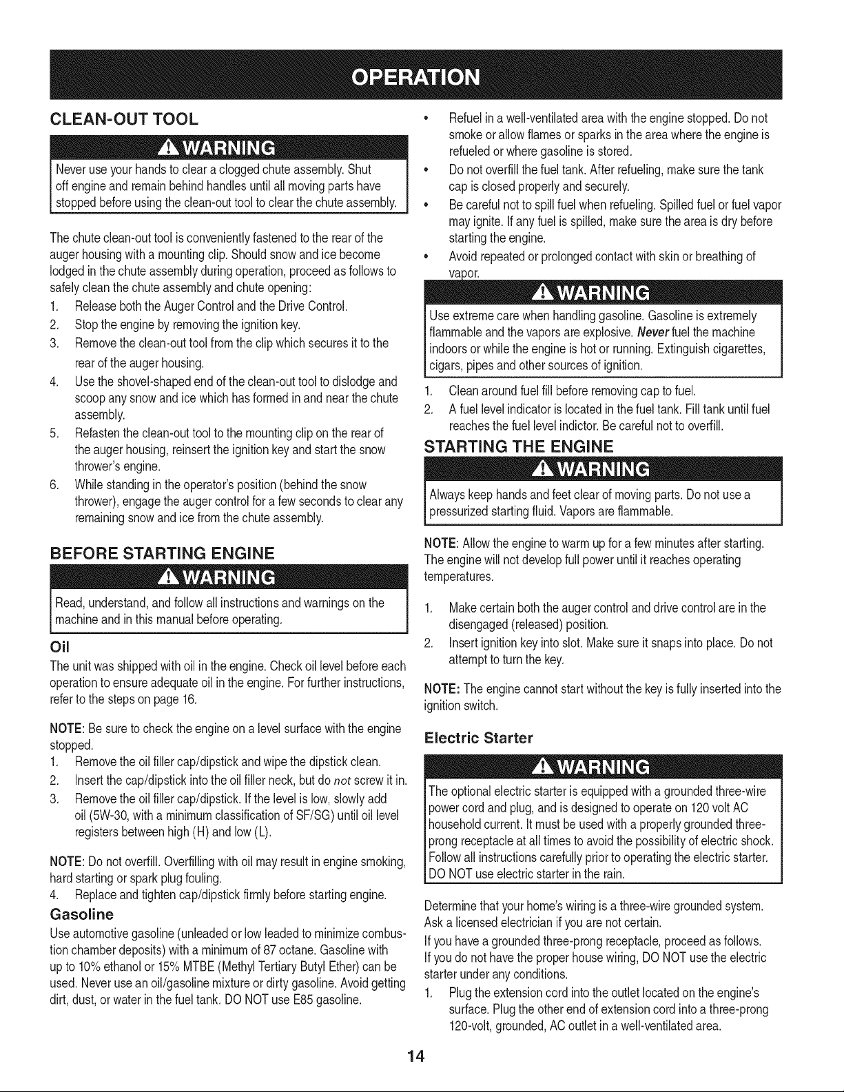
CLEAN-OUT TOOL
Neveruse yourhandsto cleara cloggedchute assembly.Shut
off engineandremainbehindhandlesuntilall movingpartshave
stoppedbeforeusingthe clean-outtoolto clear thechuteassembly.
Thechuteclean-outtool is convenientlyfastenedto the rear of the
augerhousingwith a mountingclip. Shouldsnowand ice become
lodgedin thechuteassemblyduringoperation,proceedas followsto
safelycleanthechuteassemblyandchute opening:
1. Releaseboththe AugerControlandthe DriveControl.
2. Stopthe engineby removingthe ignitionkey.
3. Removethe clean-outtoolfrom the clip whichsecuresit to the
rearof the augerhousing.
4. Use the shovel-shapedend of theclean-outtool to dislodgeand
scoopany snowand icewhich hasformedin andnearthechute
assembly.
5. Refastenthe clean-outtool to the mountingclip onthe rearof
theaugerhousing,reinsertthe ignitionkeyandstartthe snow
thrower'sengine.
6. Whilestandingin the operator'sposition(behindthesnow
thrower),engagethe augercontrolfora fewsecondsto clear any
remainingsnowand ice fromthechuteassembly.
BEFORE STARTING ENGINE
Read,understand,and followall instructionsandwarningson the
machineand inthismanualbeforeoperating.
Oil
The unitwas shippedwithoil in the engine.Checkoil levelbeforeeach
operationto ensureadequateoilin the engine.Forfurther instructions,
referto the stepsonpage 16.
NOTE:Besureto checkthe engineon a levelsurfacewith the engine
stopped.
1. Removethe oil fillercap/dipstickand wipethe dipstickclean.
2. Insertthe cap/dipstickintotheoil filler neck,butdo not screwit in.
3. Removethe oil fillercap/dipstick.If the levelis low, slowlyadd
oil (5%30, witha minimumclassificationof SF/SG)untiloil level
registersbetweenhigh(H) and low(L).
NOTE:Do notoverfill.Overfillingwith oil mayresult in enginesmoking,
hardstartingor spark plugfouling.
4. Replaceand tighten cap/dipstickfirmlybeforestartingengine.
Gasoline
Useautomotivegasoline(unleadedor low leadedto minimizecombus-
tionchamberdeposits)with a minimumof 87octane.Gasolinewith
upto 10%ethanolor 15%MTBE(MethylTertiaryButyl Ether)canbe
used.Neverusean oil/gasolinemixtureor dirty gasoline.Avoidgetting
dirt,dust,or waterin thefuel tank. DO NOTuse E85gasoline.
• Refuelin a well-ventilatedarea with the enginestopped.Do not
smokeorallowflamesor sparksin the areawherethe engineis
refueledor wheregasolineis stored.
• Donot overfillthe fueltank.After refueling,makesurethe tank
cap is closedproperlyand securely.
• Be carefulnotto spillfuel whenrefueling.Spilledfuel or fuel vapor
mayignite.If any fuelis spilled,makesurethe area is dry before
startingthe engine.
• Avoidrepeatedor prolongedcontact with skinor breathingof
)or.
Useextremecarewhen handlinggasoline.Gasolineis extremely
flammableand thevaporsare explosive.Never fuelthe machine
indoorsorwhilethe engine is hotor running.Extinguishcigarettes,
cigars,pipesandothersourcesof ignition.
1. Cleanaroundfuel fill beforeremovingcap to fuel.
2. A fuel levelindicatoris locatedin the fueltank. Fill tankuntilfuel
reachesthe fuel levelindictor.Be carefulnotto overfill.
STARTING THE ENGINE
Alwayskeep handsandfeetclearof movingparts. Donot usea
pressurizedstartingfluid.Vaporsare flammable.
NOTE:Allowthe engineto warmup for a fewminutesafter starting.
The enginewill notdevelopfull poweruntilit reachesoperating
temperatures.
1. Makecertainboththe augercontroland drivecontrolare in the
disengaged(released)position.
2. Insertignitionkey into slot.Makesure it snapsinto place.Do not
attemptto turn the key.
NOTE: Theenginecannotstartwithoutthe keyis fully insertedintothe
ignitionswitch.
Electric Starter
The optionalelectricstarteris equippedwitha groundedthree-wire
powercordand plug,andis designedto operateon 120volt AC
householdcurrent.It mustbe usedwith a properlygroundedthree-
prongreceptacleat all timesto avoidthe possibilityof electricshock.
Followall instructionscarefullyprior to operatingthe electricstarter.
DONOTuseelectricstarterinthe rain.
Determinethat yourhome'swiringis a three-wiregroundedsystem.
Aska licensedelectricianif you are notcertain.
Ifyou havea groundedthree-prongreceptacle,proceedas follows.
Ifyou do not havethe properhousewiring,DONOTusethe electric
starterunderanyconditions.
1. Plugthe extensioncord intothe outlet locatedon the engine's
surface.Plugthe otherendof extensioncord intoa three-prong
120-volt,grounded,AC outlet in a well-ventilatedarea.
14
2. Movethrottlecontrolto FAST(rabbit)_ position.
3. Movechoketo the ON position I#1 (c_d engine start). If
engineis warm,placechokein OFF position.
4. Pushprimerthree to five (3-5) times,makingsureto covervent
holewhenpushing.If engineis warm,pushprimeronlyonce.
Alwayscoverventhole whenpushing.Cool weathermayrequire
primingto berepeated.
5. Pushstarterbuttonto start engine.Oncethe enginestarts,im-
mediatelyreleasestarterbutton.Electricstarteris equippedwith
thermaloverloadprotection;systemwill temporarilyshut-downto
allowstarterto cod if electricstarterbecomesoverloaded.
TO ENGAGE DRIVE
1. Withthe throttlecontrolin the Fast(rabbit) '_ position,move
shiftleverintooneof thesix forward(F) positionsor two reverse
(R) positions.Selecta speedappropriatefor the snowconditions
anda paceyou'recomfortablewith.
NOTE: When selectinga DriveSpeed,use the slowerspeedsuntil
you are comfortableand familiarwiththe operationof the snow
thrower.
2. Squeezethe drivecontrolagainstthe handleandthe snow
throwerwill move.Releaseit anddrive motionwill stop.
6. As theenginewarms,slowlyrotatethe chokecontrol to OFF
position.If the enginefalters,restartengineandrunwithchoke
at half-chokepositionfor a shortperiodof time,andthen slowly
rotatethe chokeinto OFFposition.
7. After engineis running,disconnectpowercordfrom electric
starter.Whendisconnecting,alwaysunplugthe endat the wall
outletbeforeunpluggingtheoppositeendfrom the engine.
Recoil Starter
NOTE:NEVERrepositionthe shiftlever(changespeedsor direction
of travel)withoutfirst releasingthe drivecontrolandbringingthe snow
throwerto a completestop.Doingsowill resultin prematurewearto
the snow thrower'sdrivesystem.
TO ENGAGE AUGERS
1. Toengagethe augersandstartthrowingsnow,squeezethe
augercontrolagainstthe lefthandle.Releaseto stop theaugers.
Do notpull the starterhandlewhilethe enginerunning.
1. Movethrottlecontrolto FAST(rabbit)_ position.
2. Movechoketo the ON position I,,9"1(coldenginestart). If
engineis warm,placechokein OFF position.
3. Pushprimerthree to five (3-5) times,makingsureto covervent
holewhenpushing.If engineis warm,pushprimeronlyonce.
Alwayscoverventhole whenpushing.Cool weathermayrequire
primingto berepeated.
4. Pull gentlyon the starterhandleuntil it beginsto resist,then
pullquicklyandforcefullyto overcomethe compression.Do
not releasethe handleand allowit to snapback.Returnrope
SLOWLYto original position.If required,repeatthis step.
5. As theenginewarms,slowlyrotatethe chokecontrol to OFF
position.If the enginefalters,restartengineandrunwithchoke
at half-chokepositionfor a shortperiodof time,andthen slowly
rotatethe chokeinto OFFposition.
Toavoid unsupervisedengineoperation,neverleavethemachine
unattendedwiththe enginerunning.Turnthe engineoff after use and
removeignitionkey.
STOPPING THE ENGINE
Afteryouare finishedsnow-throwing,runenginefor a few minutes
beforestoppingto help dry offany m_sture on the engine.
1. Movethrottlecontrolto STOP_ position.
2. Removetheignitionkey.Removingthe keywill reducethe pos-
sibilityof unauthorizedstartingof theenginewhileequipmentis
not in use. Keepthe key in a safeplace.The enginecannotstart
withoutthe ignitionkey.
3. Wipeany moistureawayfrom the controlson theengine.
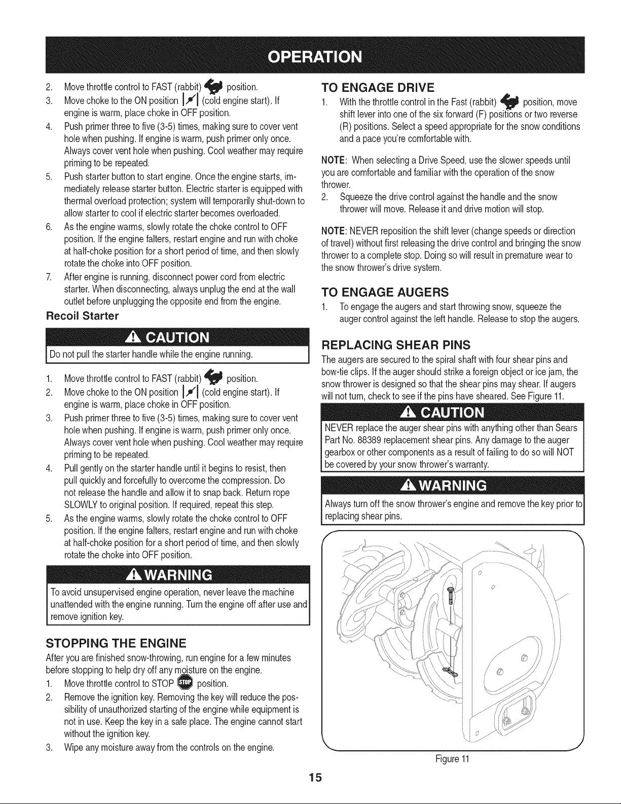
REPLACING SHEAR PINS
The augersare securedto the spiralshaftwith four shearpinsand
bow-tieclips. If the augershouldstrikea foreignobject or icejam, the
snowthroweris designedso thatthe shearpins mayshear.If augers
will not turn,checkto seeif the pinshavesheared.SeeFigure11.
NEVERreplacethe augershearpinswithanythingotherthanSears
PartNo.88389replacementshearpins.Anydamageto theauger
j gearboxorothercomponentsas,aresultof failingto do sowill NOT
[be coveredbyyour snowthrowers warranty.
Alwaysturnoff the snowthrower'sengineandremovethe keyprior to
replacingshearpins.
iJ
Figure11
15
MAINTENANCE SCHEDULE
Beforeperforminganytypeof maintenance/service,disengageall
controlsandstoptheengine.Waituntilall movingpartshavecometo
acompletestop.Disconnectsparkplugwireandgrounditagainstthe
enginetopreventunintendedstarting.Alwayswearsafetyglassesduring
operationor whileperforminganyadjustmentsor repairs.
Followthe maintenanceschedulegivenbelow.Thischart describes
serviceguidelinesonly. Usethe ServiceLogcolumnto keeptrackof
completedmaintenancetasks.To locate the nearest Sears Service
Centeror to scheduleservice,simplycontactSears at
1-800-4-MY-HOME®.
EachUseandevery5
hours
1st5 hours
Annuallyor 25hours
Annuallyor 50hours
Annuallyor 100hours
BeforeStorage
1. Engineoil level
2. Looseor missinghardware
3. Unit and engine.
1. Engineoil
1. Sparkplug
2. Controllinkagesand pivots
3. Wheels
4. Gearshaft andAugershaft
5. 4-WayChuteControlTM
1. Engineoil
1. Sparkplug
1. Fuelsystem
1. Check
2. Tightenor replace
3. Clean
1. Change
1. Check
2. Lubewithlightoil
3. Lubewithmultipurposeautogrease
4. Lubewithlightoil
5. Checkfor cableslackness
1. Change
1. Change
1. Runengineuntilit stopsfrom lack
of fuel
ENGINE MAINTENANCE
Beforelubricating,repairing,or inspecting,disengageall controls
Iandstopengine.Wait untilall movingpartshavecometo a complete
_stop.
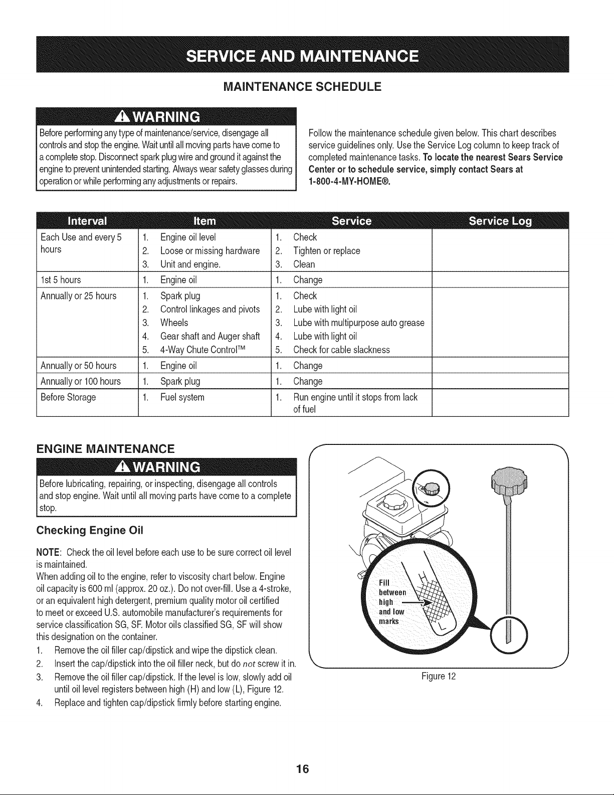
Checking Engine Oil
NOTE: Checktheoil levelbeforeeachuseto besurecorrectoil level
is maintained.
Whenaddingoilto the engine,referto viscositychart below.Engine
oilcapacityis 600ml (approx.20 oz.). Donot over-fill.Usea 4-stroke,
oran equivalenthighdetergent,premiumquality motoroil certified
to meet or exceedU.S.automobilemanufacturer'srequirementsfor
serviceclassificationSG, SR MotoroilsclassifiedSG, SFwill show
thisdesignationonthe container.
1. Removethe oil fillercap/dipstickand wipethe dipstickclean.
2. Insertthe cap/dipstickintotheoil filler neck,butdo not screwit in.
3. Removethe oil fillercap/dipstick.If the levelis low, slowlyadd oil
untiloil levelregistersbetweenhigh(H) and low(L), Figure12.
4. Replaceand tighten cap/dipstickfirmlybeforestartingengine.
f
Figure12
16

Changing Engine Oil
NOTE:Changethe engineoilafterthe first 5 hoursof operationand
oncea seasonorevery 50 hoursthereafter.
1. Drainfuelfromtankby runningengineuntilthe fuel tankis empty.
Besurefuel fill cap is secure.
2. Placesuitableoil collectioncontainerunderoil drain plug.
3. Removeoil drain plug.See Figure13.
4. Tip engineto drainoil intothe container.Usedoil mustbe
disposedof at a propercollectioncenter.
Usedoil is a hazardouswasteproduct.Disposeof usedoil properly.
Donotdiscardwith householdwaste.Checkwith yourlocalauthori-
tiesor SearsServiceCenterfor safedisposal/recyclingfacilities.
.
6.
Reinstallthe drain plugandtightenit securely.
Refillwiththe recommendedoil and checkthe oil level.See
RecommendedOil Usagechart.Theengine'soil capacityis 20
ounces.
u i
Synthetic
(0F)-40o-20 o 0o 200 400
("c) -30° -20 ° -10° 0°
DONOTuse non detergentoil or 2-strokeengineoil. It couldshorten
the engine'sservicelife.
7. Reinstallthe oilfillercap/dipsticksecurely.
Thoroughlywashyour handswithsoapandwateras soonas
possibleafterhandling usedoil.
Checking Spark Plug
Oil Drain
Plug
Figure13
Spark Plug
©
SparkPlug Boot
Figure14
J
DO NOTcheckfor sparkwithspark plug removed.DO NOTcrank
enginewithsparkplug removed.
Ifthe enginehasbeenrunning,the mufflerwill bevery hot.Becareful
notto touch the muffler.
NOTE: Checkthe sparkplugoncea seasonorevery25hoursof
operation.Changethe sparkplugoncea seasonor every 100hours.
Toensureproperengineoperation,the sparkplugmustbe properly
gappedandfreeof deposits.
1. Removethe sparkplug bootand usea spark plugwrenchto
removethe plug.See Figure14.
2. Visuallyinspectthe sparkplug. Discardthe sparkplugif thereis
apparentwear,or if the insulatoris crackedor chipped.Cleanthe
sparkplugwith a wire brushif it is to be reused.
17
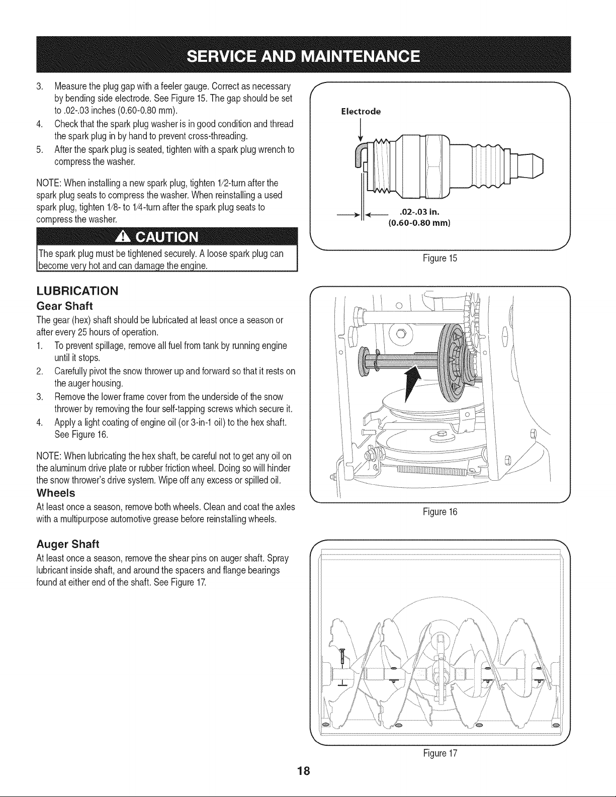
3. Measurethe pluggapwitha feelergauge.Correctas necessary
by bendingsideelectrode.SeeFigure15.The gap shouldbe set
to .02-.03inches (0.60-0.80ram).
4. Checkthat thespark plug washeris ingoodconditionand thread
the sparkplug in by handto preventcross-threading.
5. Afterthe sparkplug is seated,tightenwith a spark plugwrenchto
compressthe washer.
NOTE:Wheninstallinga newsparkplug,tighten1/2-turnafterthe
sparkplugseatsto compressthe washer.Whenreinstallinga used
sparkplug,tighten 1/8-to 1/4-turnafter the sparkplugseatsto
compressthe washer.
hot and can ine.
f
Electrode
.02=.03 in.
(0.60=0.80 rnrn)
J
Figure15
LUBRICATION
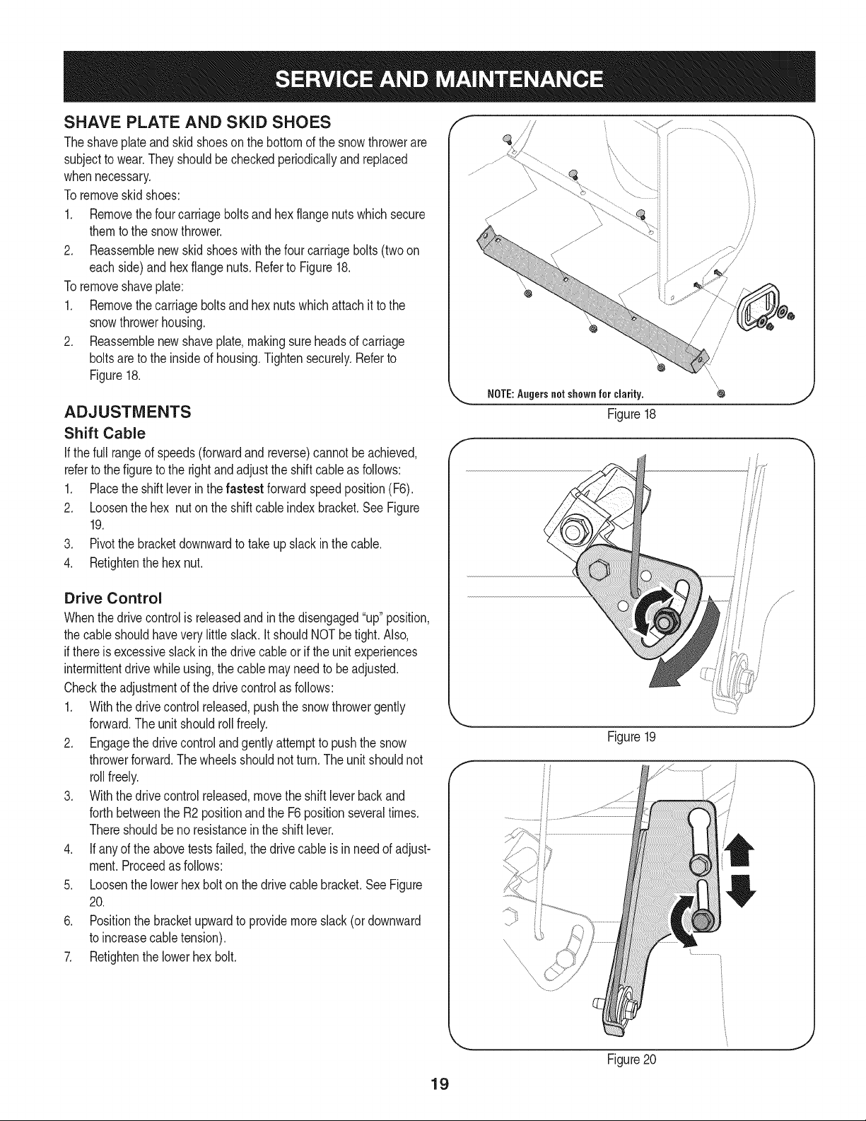
Gear Shaft
Thegear(hex)shaft shouldbe lubricatedat leastoncea seasonor
afterevery25 hoursof operation.
1. Topreventspillage,removeall fuel fromtank by runningengine
until it stops.
2. Carefullypivotthe snowthrowerupand forwardso that it restson
theaugerhousing.
3. Removethe lowerframecoverfromthe undersideof the snow
throwerby removingthe four self-tappingscrewswhichsecureit.
4. Applya lightcoatingof engineoil (or3-in-1oil) to the hexshaft.
SeeFigure16.
NOTE:Whenlubricatingthe hexshaft, be carefulnotto get any oil on
thealuminumdriveplateor rubberfrictionwheel. Doingsowill hinder
the snowthrower'sdrive system.Wipeoff anyexcessor spilledoil.
Wheels
At least oncea season,removebothwheels.Cleanandcoattheaxles
witha multipurposeautomotivegreasebeforereinstallingwheels.
Figure16
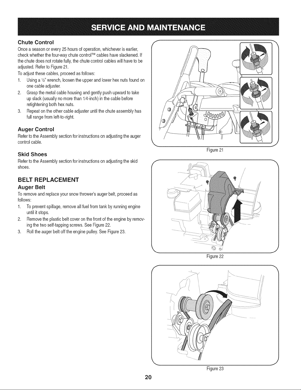
Auger Shaft
At least oncea season,removethe shearpinson augershaft.Spray
lubricantinsideshaft,andaroundthe spacersandflangebearings
foundat eitherendof the shaft.SeeFigure17.
f
\
18
Figure17
J
SHAVE PLATE AND SKiD SHOES
Theshaveplateand skidshoeson the bottomof the snowthrowerare
subjectto wear.Theyshouldbe checkedperiodicallyand replaced
whennecessary.
Toremoveskidshoes:
1. Removethefour carriageboltsandhexflangenutswhichsecure
themtothe snowthrower.
2. Reassemblenew skidshoeswiththefour carriagebolts (two on
eachside)and hexflangenuts.Referto Figure18.
Toremoveshaveplate:
1. Removethecarriageboltsand hexnutswhichattachit to the
snowthrowerhousing.
2. Reassemblenew shaveplate,makingsureheadsof carriage
boltsare to the insideof housing.Tightensecurely.Referto
Figure18.
ADJUSTMENTS
Shift Cable
If thefull rangeof speeds(forwardandreverse)cannotbe achieved,
referto the figureto the rightandadjustthe shift cableas follows:
1. Placethe shiftleverin thefastest forward speedposition(F6).
2. Loosenthe hex nuton the shiftcable indexbracket.SeeFigure
19.
3. Pivotthe bracketdownwardto take up slack inthe cable.
4. Retightenthehex nut.
Drive Control
Whenthedrivecontrolis releasedandin thedisengaged"up"position,
the cableshouldhaveverylittle slack.It shouldNOTbetight. Also,
if thereis excessiveslackin thedrive cableor if the unitexperiences
intermittentdrivewhileusing,the cable mayneed to beadjusted.
Checktheadjustmentof the drivecontrolas follows:
1. Withthedrivecontrolreleased,pushthe snowthrowergently
forward.The unitshouldrollfreely.
2. Engagethe drivecontrolandgentlyattemptto pushthe snow
throwerforward.Thewheelsshouldnotturn.The unitshouldnot
rollfreely.
3. With thedrivecontrol released,movethe shift leverbackand
forthbetweenthe R2positionand the F6 positionseveraltimes.
Thereshouldbeno resistancein the shiftlever.
4. If anyof the abovetests failed,the drivecable is in needof adjust-
ment.Proceedas follows:
5. Loosenthe lowerhexbolt on the drivecable bracket.SeeFigure
20.
6. Positionthe bracketupwardto providemoreslack(or downward
to increasecabletension).
7. Retightenthe lowerhex bolt.
f
Ji
i/
NOTE:Augersnot shown for clarity.
Figure18
Figure19
Figure20
19
Chute Control
Oncea seasonorevery 25 hoursof operation,whicheveris earlier,
checkwhetherthe four-waychutecontrolTM cables haveslackened.If
thechutedoesnot rotatefully,the chutecontrolcables will haveto be
adjusted.Referto Figure21.
Toadjustthesecables,proceedas follows:
1. Usinga 1/2"wrench,loosenthe upperand lowerhexnuts foundon
onecableadjuster.
2. Graspthe metalcablehousingandgentlypushupwardto take
up slack(usuallynomorethan 1/4-inch)in the cablebefore
retighteningboth hexnuts.
3. Repeaton the othercableadjusteruntilthe chuteassemblyhas
full rangefrom left-to-right.
Auger Control
Referto the Assemblysectionfor instructionsonadjustingtheauger
controlcable.
Skid Shoes
Referto the Assemblysectionfor instructionsonadjustingthe skid
shoes.
BELT REPLACEMENT
Auger Belt
To removeand replaceyoursnow thrower'sauger belt, proceedas
follows:
1. Topreventspillage,removeall fuel fromtank by runningengine
until itstops.
2. Removethe plasticbelt coveron the front of the engineby remov-
ingthe twoself-tappingscrews.SeeFigure22.
3. Rollthe augerbeltoff theenginepulley.See Figure23.
f
Figure21
J
\
Figure22
f
2O
Figure23
4. Carefullypivotthesnowthrowerupandforwardsothatitrestson
theaugerhousing.
5. Removetheframecoverfromtheundersideofthesnowthrower
byremovingfourself-tappingscrewswhichsecureit.SeeFigure
24.
6. Removethebeltasfollows.RefertoFigure25.
a. Loosenandremovetheshoulderscrewwhichactsasabelt
keeper.
b. Unhookthesupportbracketspringfromtheframe.
7. Removethebeltfromaroundtheaugerpulley,andslipthebelt
betweenthesupportbracketandtheaugerpulley.SeeFigure26.
8. Reassembleaugerbeltbyfollowinginstructionsinreverseorder.
9. PerformtheAugerControltestoutlinedintheAssemblysection
ofthismanual.
NOTE:DoNOTforgettoreinstalltheshoulderscrewandreconnect
thespringtotheframeafterinstallingareplacementaugerbelt.
/
Figure24
f
Figure25
f
21
Figure26
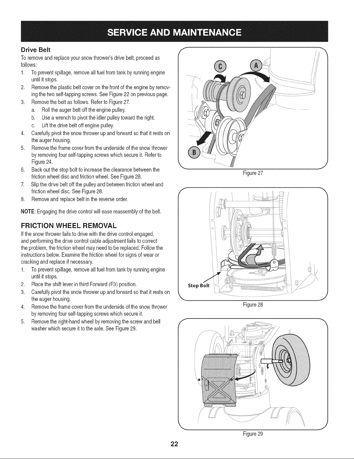
Drive Belt
To removeand replaceyoursnow thrower'sdrivebelt,proceedas
follows:
1. Topreventspillage,removeall fuel fromtank by runningengine
until it stops.
2. Removethe plasticbelt coveron the front of the engineby remov-
ingthe twoself-tappingscrews.SeeFigure22 on previouspage.
3. Removethe beltas follows.Referto Figure27.
a. Rollthe augerbeltoff theenginepulley.
b. Use a wrenchto pivotthe idlerpulleytowardthe right.
c. Lift the drivebelt off engine pulley.
4. Carefullypivotthe snowthrowerup andforwardsothat it restson
the augerhousing.
5. Removethe framecoverfromthe undersideof thesnowthrower
by removingfour self-tappingscrewswhich secureit. Referto
Figure24.
6. Back outthe stopbolt to increasethe clearancebetweenthe
frictionwheeldiscandfrictionwheel.See Figure28.
7. Slipthe drivebelt offthe pulleyandbetweenfrictionwheeland
frictionwheeldisc.SeeFigure28.
8. Removeand replacebelt inthe reverseorder.
NOTE:Engagingthedrive controlwillease reassemblyof the belt.
FRICTION WHEEL REMOVAL
Ifthe snowthrowerfailsto drive with thedrivecontrol engaged,
andperformingthe drivecontrolcableadjustmentfails to correct
the problem,the frictionwheelmayneedto be replaced.Followthe
instructionsbelow.Examinethe frictionwheelfor signsof wearor
crackingand replaceif necessary.
1. Topreventspillage,removeall fuel fromtank by runningengine
until it stops.
2. Placethe shiftleverin third Forward(F3) position.
3. Carefullypivotthe snowthrowerupand forwardso that it restson
theaugerhousing.
4. Removethe frame coverfrom the undersideof the snow thrower
by removingfourself-tappingscrewswhichsecureit.
5. Removethe right-handwheelby removingthe screwand bell
washerwhichsecureit to theaxle.See Figure29.
Figure27
J
f
Stop Bolt
Figure28
f
Figure29
J
22
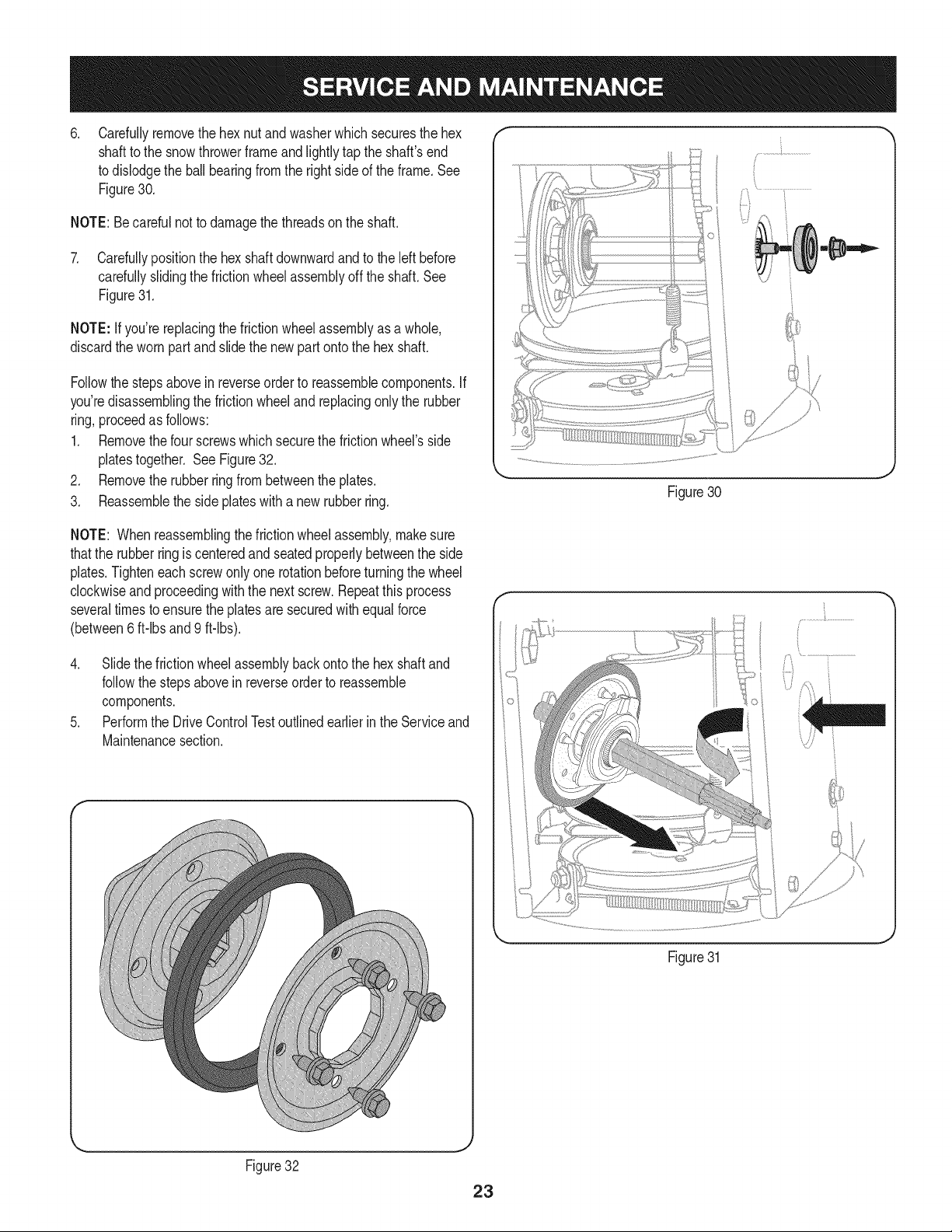
.
Carefullyremovethe hexnut andwasherwhich securesthehex
shaftto the snowthrowerframeand lightlytap the shaft'send
to dislodgethe ball bearingfrom the rightsideof the frame.See
Figure30.
NOTE:Becarefulnot to damagethe threadson the shaft.
7. Carefullypositionthe hexshaftdownwardandto the left before
carefullyslidingthe frictionwheelassemblyoff the shaft.See
Figure31.
NOTE: If you'rereplacingthe frictionwheelassemblyas a whole,
discardthe wornpartand slidethe newpart ontothe hexshaft.
Followthe stepsabovein reverseorder to reassemblecomponents.If
you'redisassemblingthe frictionwheeland replacingonly the rubber
ring,proceedas follows:
1. Removethefour screwswhich securethe frictionwheel'sside
platestogether. SeeFigure32.
2. Removethe rubberringfrombetweenthe plates.
3. Reassemblethe side plateswith a newrubberring.
Figure30
NOTE: Whenreassemblingthe frictionwheelassembly,makesure
thatthe rubberringis centeredand seatedproperlybetweenthe side
plates.Tighteneachscrewonlyone rotationbeforeturningthe wheel
clockwiseandproceedingwiththe next screw.Repeatthis process
severaltimes toensurethe platesaresecuredwith equalforce
(between6 ft-lbsand 9 ft-lbs).
4. Slide the frictionwheelassemblybackonto the hexshaftand
followthestepsabovein reverseorderto reassemble
components.
5. Performthe DriveControlTestoutlinedearlierin the Serviceand
Maintenancesection.
Figure31
Figure32
23

Ifthe snowthrowerwillnot be usedfor30 daysor longer,or if it is the endof the snowseasonwhenthe lastpossibilityof snowis gone,the
equipmentneedsto be storedproperly.Followstorageinstructionsbelowto ensuretop performancefromthe snowthrowerfor manymoreyears.
PREPARING ENGINE
Enginesstoredover30 days need to bedrainedof fuel to prevent
deteriorationandgumfrom formingin fuel systemor onessential
carburetorparts.If thegasolineinyourenginedeterioratesduring
storage,youmay needto havethe carburetor,and otherfuel system
components,servicedor replaced.
1. Removeall fuel fromtank by runningengineuntil it stops.
2. Changethe engineoil.
3. Removesparkplug and pour approximately1 oz. (30 rnl) of clean
engineoil intothe cylinder.Pullthe recoilstarterseveraltimesto
distributetheoil, and reinstallthe spark plug.
4. Cleandebrisfrom aroundengine,and under,around,andbehind
muffler.Applya lightfilmof oil on anyareasthat are susceptible
to rust.
• Storeina clean,dry andwellventilatedareaawayfromanyap-
pliancethat operateswith a flame or pilotlight, such as a furnace,
waterheater,or clothesdryer.Avoidany areawitha spark
producingelectricmotor,or wherepowertools are operated.
Neverstoresnowthrowerwithfuel intank indoorsor inpoorlyventi-
latedareas,wherefuel fumesmayreachan openflame,sparkor pilol
lightas on a furnace,waterheater,clothesdryer or gas appliance.
• If possible,avoidstorageareaswithhigh humidity.
• Keepthe enginelevelin storage.Tiltingcan causefuel oroil
leakage.
PREPARING SNOW THROWER
Whenstoringthe snowthrowerin anunventilatedormetal stor-
age shed,careshouldbetaken to rustprooftheequipment.Using
a light oil or silicone,coat theequipment,especiallyanychains,
springs,bearingsand cables.
• Removealldirt fromexteriorof engineand equipment.
• Followlubricationrecommendations.
• Storeequipmentin a clean,dry area.
24
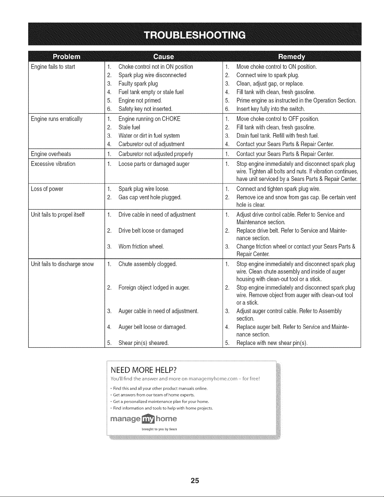
Enginefailsto start
Enginerunserratically
Engineoverheats
Excessivevibration
Lossof power
Unitfailsto propel itself
Unitfailsto dischargesnow
1. Chokecontrolnot inON position
2. Sparkplugwire disconnected
3. Faultysparkplug
4. Fueltank emptyor stale fuel
5. Enginenotprimed.
6. Safetykeynot inserted.
1. Enginerunningon CHOKE
2. Stalefuel
3. Wateror dirt in fuel system
4. Carburetorout of adjustment
1. Carburetornot adjustedproperly
1. Loosepartsor damagedauger
1. Sparkplugwire loose.
2. Gascap ventholeplugged.
1. Drivecable inneedof adjustment
2. Drivebelt looseordamaged
3. Wornfrictionwheel.
1. Chuteassemblyclogged.
2. Foreignobject lodgedin auger.
3. Augercablein needof adjustment.
4. Augerbelt looseordamaged.
5. Shearpin(s) sheared.
1. Movechokecontrolto ONposition.
2. Connectwireto sparkplug.
3. Clean,adjustgap,or replace.
4. Filltank with clean, freshgasoline.
5. Primeengineas instructedin the OperationSection.
6. Insertkeyfully intothe switch.
1. Movechokecontrolto OFFposition.
2. Filltank with clean, freshgasoline.
3. Drainfueltank. Refillwithfreshfuel.
4. ContactyourSearsParts& RepairCenter.
1. ContactyourSearsParts& RepairCenter.
1. Stopengineimmediatelyand disconnectsparkplug
wire.Tightenall boltsand nuts.Ifvibrationcontinues,
haveunitservicedbya SearsParts& RepairCenter.
1. Connectand tightenspark plugwire.
2. Removeice and snow from gascap. Be certainvent
holeis clear.
1. Adjustdrivecontrolcable. Referto Serviceand
Maintenancesection.
2. Replacedrive belt.Referto ServiceandMainte-
nancesection.
3. Changefrictionwheelor contactyour SearsParts&
RepairCenter.
1. Stopengineimmediatelyand disconnectsparkplug
wire.Cleanchuteassemblyandinsideof auger
housingwith clean-outtool ora stick.
2. Stopengineimmediatelyand disconnectsparkplug
wire.Removeobjectfromaugerwith clean-outtool
ora stick.
3. Adjustaugercontrolcable. Referto Assembly
section.
4. Replaceauger belt. Referto ServiceandMainte-
nancesection.
5. Replacewith new shearpin(s).
25
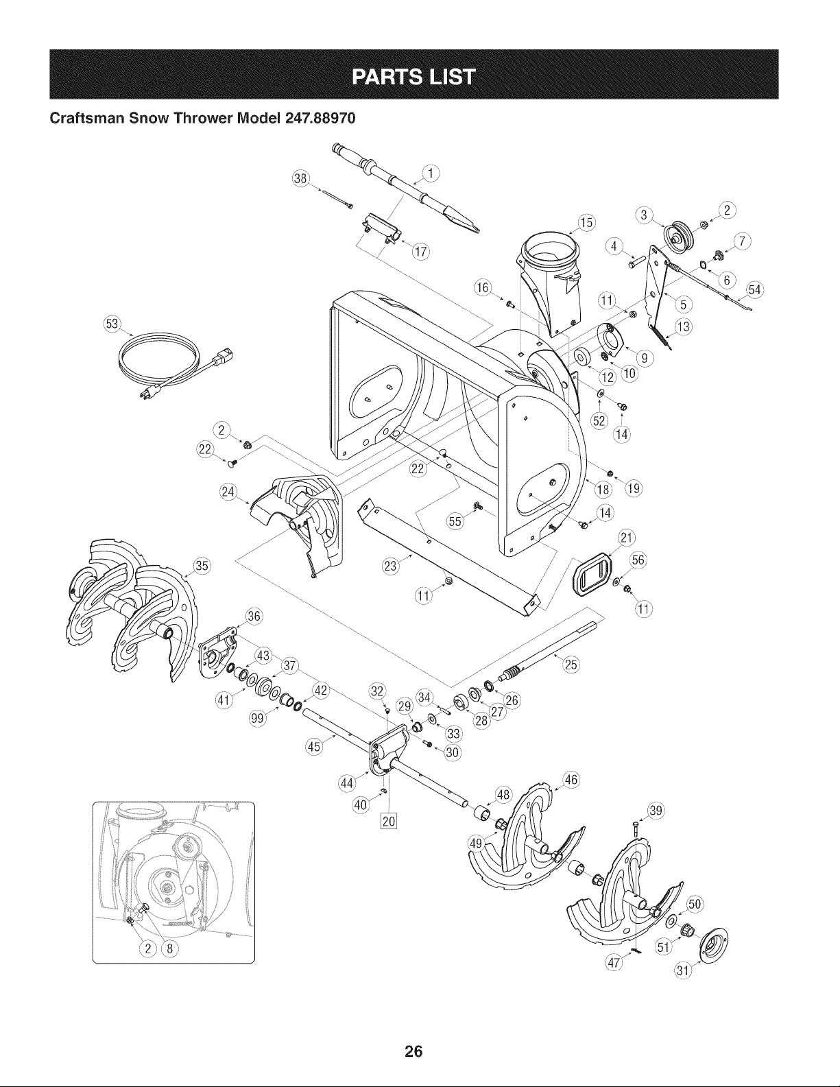
Craftsman Snow Thrower IViodel 247.88970
[]
/
/
/
26
Craftsman Snow Thrower IViodel 247.88970
D = 0
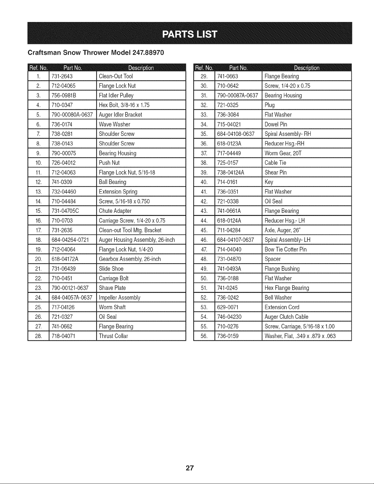
731-2643 Clean-OutTool
2. 712-04065 FlangeLockNut
3. 756-0981B FlatIdlerPulley
4. 710-0347 HexBolt,3/8-16x 1.75
5. 790-00080A-0637 AugerldlerBracket
6. 736-0174 WaveWasher
7. 738-0281 ShoulderScrew
, 738-0143 ShoulderScrew
9. 790-00075 BearingHousing
10. 726-04012 PushNut
11. 712-04063 FlangeLockNut,5/16-18
12. 741-0309 Ball Bearing
13. 732-04460 ExtensionSpring
14. 710-04484 Screw,5/16-18x 0.750
15. 731-04705C ChuteAdapter
16. 710-0703 CarriageScrew,1/4-20x 0.75
17. 731-2635 Clean-outToolMtg.Bracket
18. 684-04264-0721 AugerHousingAssembly,26-inch
19. 712-04064 FlangeLock Nut,1/4-20
20. 618-04172A GearboxAssembly,26-inch
21. 731-06439 SlideShoe
22. 710-0451 CarriageBolt
23. 790-00121-0637 ShavePlate
24. 684-04057A-0637 ImpellerAssembly
25. 717-04126 WormShaft
26. 721-0327 OilSeal
27. 741-0662 FlangeBearing
28. 718-04071 ThrustCollar
D = O
741-0663 FlangeBearing
30. 710-0642 Screw,1/4-20x 0.75
31. 790-00087A-0637 BearingHousing
32. 721-0325 Plug
33. 736-3084 FiatWasher
34. 715-04021 DowelPin
35. 684-04108-0637 SpiralAssembly-RH
36. 618-0123A ReducerHsg.-RH
37. 717-04449 WormGear,20T
38. 725-0157 CableTie
39. 738-04124A ShearPin
40. 714-0161 Key
41. 736-0351 Fiat Washer
42. 721-0338 OilSeal
43. 741-0661A FlangeBearing
44. 618-0124A ReducerHsg.-LH
45. 711-04284 Axle,Auger,26"
46. 684-04107-0637 SpiralAssembly-LH
47. 714-04040 BowTie CotterPin
48. 731-04870 Spacer
49. 741-0493A FlangeBushing
50. 736-0188 FiatWasher
51. 741-0245 Hex FlangeBearing
52. 736-0242 BellWasher
53. 629-0071 ExtensionCord
54. 746-04230 AugerClutchCable
55. 710-0276 Screw,Carriage,5/16-18x 1.00
56. 736-0159 Washer,Fiat, .349x .879x .063
27
Craftsman Snow Thrower Model 247.88970
%
i i
28
Craftsman Snow Thrower IViodel 247.88970
m = W
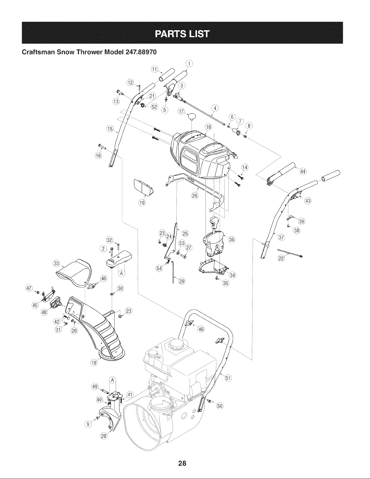
684-04112B HandleEngagementAssemblyRH
2. _ 738-04194 _ FlangeShoulderScrew
3. 731-04894D LockPlate
4. 684-04250 PivotRod
5. 735-0199A RubberBumper
6. 710-3069 Screw,1/4-20x .500
7. 731-04896B ClutchLockCam
8. 712-04081A ShoulderNut, 1/4-20
9. 710-0627 HexScrew,5/16-24x .750
10. 731-06440 LowerChute
11. 720-0274 HandleGrip
12. 710-1233 Screw,#10-24x 0.375
13. 738-04348 ShoulderScrew,1/4-20
14. 710-04586 Screw,1/4-20x 1.625
15. 749-04190A-0637 UpperHandleRH
16. 710-0449 CarriageScrew,5/16-18x 2.25
17. 720-04039 Shift Knob
18. 731-05335A HandlePanel
19. 731-05324 Lens
20. 710-04071 CarriageBolt,5/16-18x 1.0
21. _63104134B HandleClutchLock RH Assy
22. 725-0157 CableTie
23. 712-04064 FlangeLockNut, 1/4-20
24. 732-0193 CompressionSpring
25. 790-00311-0637 ShiftLever
26. 790-00248B-0637 PanelBracket
27. 738-04125 ShoulderScrew
D = O
684-04311-0637 ChuteSupportBracket
29. 746-04396 SpeedSelectorCable
30. 736-0463 FiatWasher,.25 x .630x .0515
31. 710-0895 Hi-LoScrew,1/4-15x .75
32. 710-0606 HexScrew,1/4-20x 1.50
33. 731-04427A UpperChute
34. 790-00155A-0637 JoystickBracket
35. 710-04187 Hi-LoScrew,1/4-15x 0.5
36. 684-04331 4-WayChuteControlTM Assembly
37. 749-04191A-0637 UpperHandleLH
38. 710-04326 Screw,#8-16x 0.50
39. 732-04219C ClutchLockSpring
40. 712-3087 WingNut, 1/4-20
41. 714-04040 BowTie CotterPin
42. 710-0262 CarriageBolt, 5/16-18x 1.50
43. 631-04133A HandleClutchLock LHAssy
44. 684-04111B HandleEngagementAssemblyLH
45. 784-5594-0637 CableBracket
46. 720-0284 WingKnob
47. 712-04063 FlangeLock Nut,5/16-18
48. 731-06451 ChuteTiltCableGuide
49. 711-04469A ClevisPin
50. 710-04484 Screw,5/16-18x 0.75
51. 749-04138A-0637 LowerHandle
52. 732-04238 TorsionSpring
53. 736-0267 FiatWasher
54. 714-0145 ClickPin
29
Craftsman Snow Thrower Model 247.88970
.,"'"'
................................................;;,,
\
0_'
3O
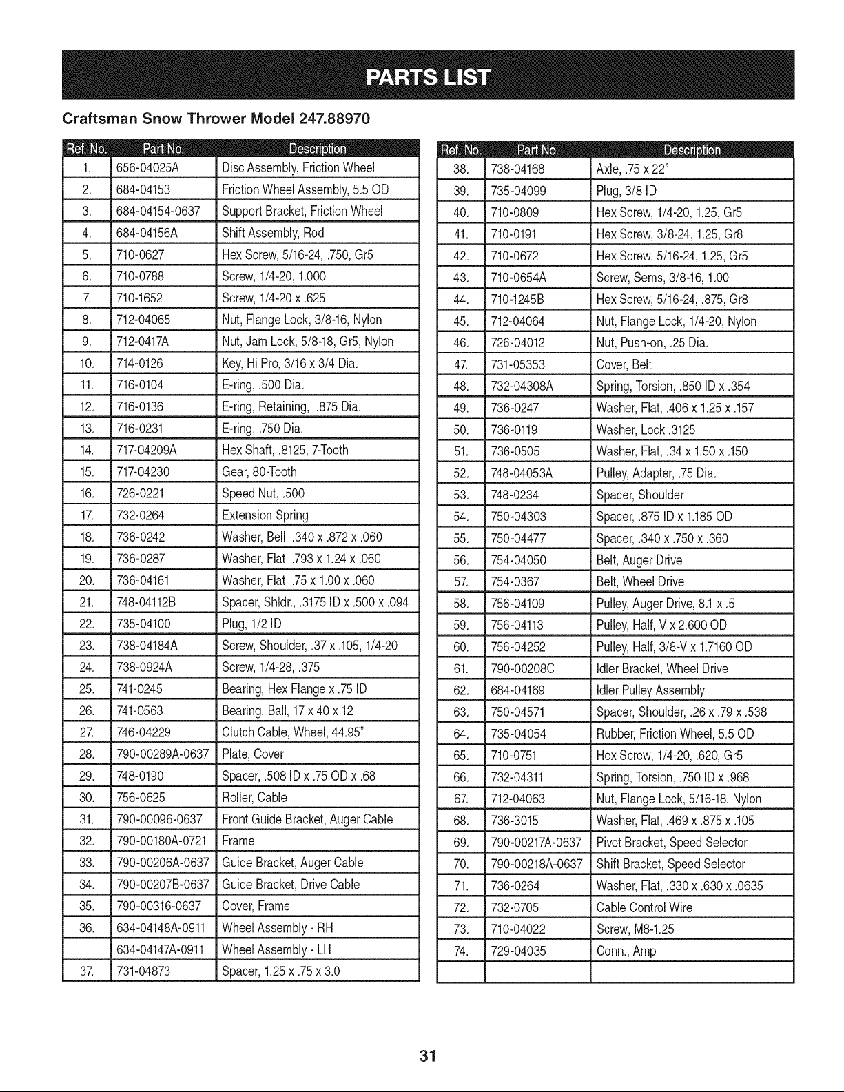
Craftsman Snow Thrower IViodel 247.88970
D = 0 e
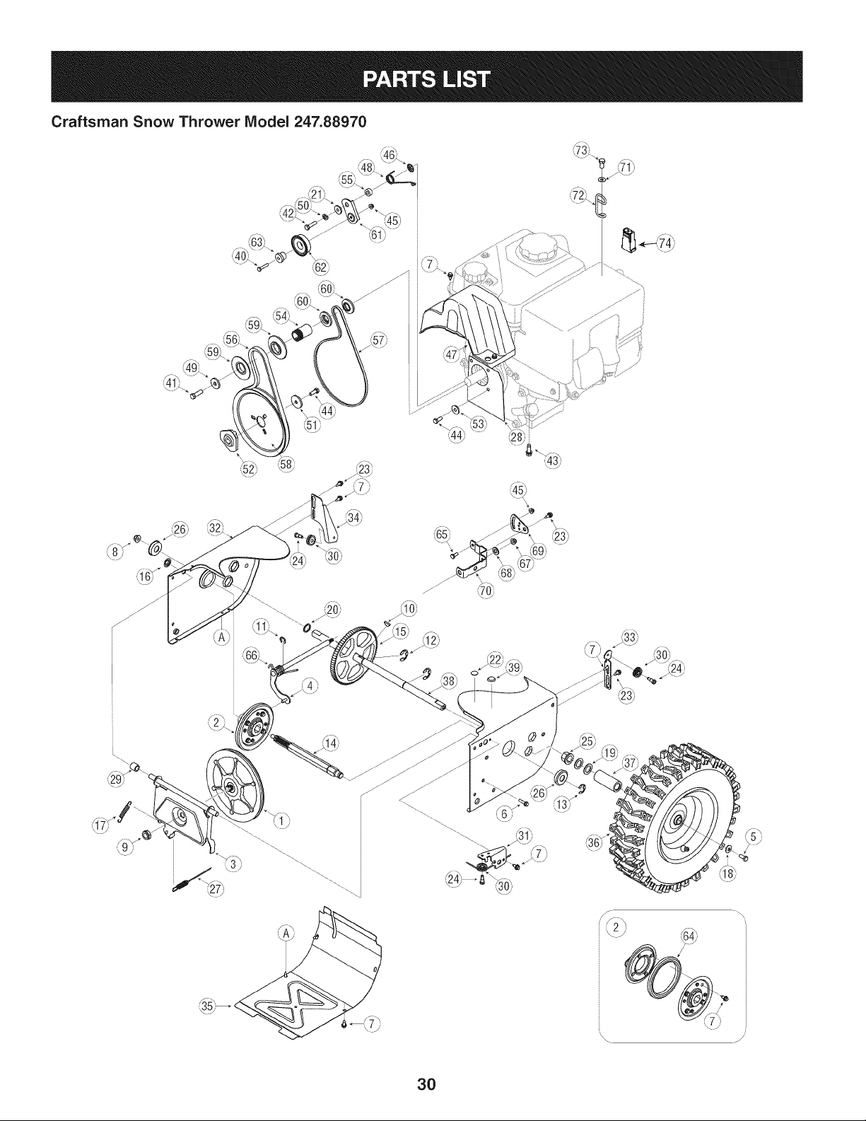
656-04025A DiscAssembly,FrictionWheel
2. 684-04153 FrictionWheelAssembly,5.50D
3; L684-04154-0637 .Supp°rt Bracket,FrictionWheel
4. 684-04156A ShiftAssembly,Rod
5. 710-0627 HexScrew,5/16-24,.750,Gr5
6. 710-0788 Screw,1/4-20,1.000
7. 710-1652 Screw,1/4-20x .625
8. 712-04065 Nut, FlangeLock,3/8-16,Nylon
9. 712-0417A Nut,JamLock,5/8-18,Gr5,Nylon
10. 714-0126 Key,Hi Pro,3/16x 3/4 Dia.
11. 716-0104 E-ring,.500 Dia.
12. 716-0136 E-ring,Retaining, .875Dia.
13. 716-0231 E-ring,.750Dia.
14. 717-04209A Hex Shaft,.8125,7-Tooth
15. 717-04230 Gear,80-Tooth
16. 726-0221 SpeedNut, .500
17. 732-0264 ExtensionSpring
18. 736-0242 Washer,Bell, .340x .872x .060
19. 736-0287 Washer,Flat, .793x 1.24x .060
20. 736-04161 Washer,Flat, .75x 1.00x .060
21. 748-04112B Spacer,Shldr.,.3175ID x .500x .094
22. 735-04100 Plug,1/2 ID
23. 738-04184A Screw,Shoulder,.37 x .105,1/4-20
24. 738-0924A Screw,1/4-28,.375
25. 741-0245 Bearing,Hex Flangex .75ID
26. 741-0563 Bearing,Ball, 17x 40 x 12
27. ,746-04229 Clutch Cab!e,Wheel,44.95'
28. 790-00289A-0637 Plate,Cover
29. 748-0190 Spacer,.508IDx .75ODx .68
30. 756-0625 Roller,Cable
31. 790-00096-0637 FrontGuideBracket,AugerCable
32. 790-00180A-0721 Frame
33. 790-00206A-0637 Guide Bracket,AugerCable
34. 790-00207B-0637 Guide Bracket,DriveCable
35. 790-00316-0637 Cover,Frame
36. 634-04148A-0911 WheelAssembly- RH
634-04147A-0911 WheelAssembly- LH
37. 731-04873 Spacer,1.25x .75x 3.0
738-04168
39. 735-04099
40. 710-0809
41. 710-0191
42. 710-0672
43. 710-0654A
44. 710-1245B
45. 712-04064
46. 726-04012
4_ 731-05353
48. 732-04308A
49. 736-0247
50. 736-0119
51. 736-0505
D = W O
Axle,.75x 22"
Plug,3/8 ID
HexScrew,1/4-20,1.25,Gr5
HexScrew,3/8-24,1.25,Gr8
HexScrew,5/16-24,1.25,Gr5
Screw,Seres,3/8-16,1.00
HexScrew,5/16-24,.875,Gr8
Nut, FlangeLock,1/4-20,Nylon
Nut, Push-on,.25Dia.
Cover,Belt
Spring,Torsion,.850 IDx .354
Washer,Flat,.406x 1.25x .157
Washer,Lock .3125
Washer,Flat,.34 x 1.50x .150
52. 748-04053A Pulley,Adapter,.75Dia.
53. 748-0234 Spacer,Shoulder
54. 750-04303 Spacer,.875IDx 1.185OD
55. 750-04477 Spacer,.340x .750x .360
56. 754-04050 Belt,Auger Drive
57. 754-0367 Belt,WheelDrive
58. 756-04109 Pulley,AugerDrive,8.1x .5
59. 756-04113 Pulley,Half,Vx 2.600OD
60. 756-04252 Pulley,Half,3/8-Vx 1.7160OD
61. 790-00208C Idler Bracket,WheelDrive
62. 684-04169 Idler PulleyAssembly
63. 750-04571
64. 735-04054
65. 710-0751
66. 732-04311
6_ 712-04063
68. 736-3015
69. 790-00217A-0637
70. 790-00218A-0637
71. 736-0264
72. 732-0705
73. 710-04022
74. 729-04035
Spacer,Shoulder,.26x .79x .538
Rubber,FrictionWheel,5.50D
HexScrew,1/4-20,.620,Gr5
Spring,Torsion,.750ID x .968
Nut, FlangeLock,5/16-18,Nylon
Washer,Flat,.469x .875x .105
PivotBracket,SpeedSelector
Shift Bracket,SpeedSelector
Washer,Fiat,.330x .630x .0635
CableControlWire
Screw,M8-1.25
Conn.,Amp
31
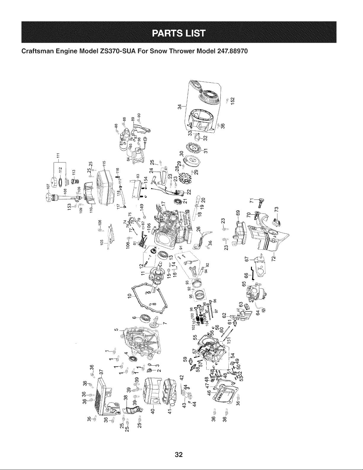
Craftsman Engine Model ZS370-SUA For Snow Thrower Model 247.88970
7
o3
32
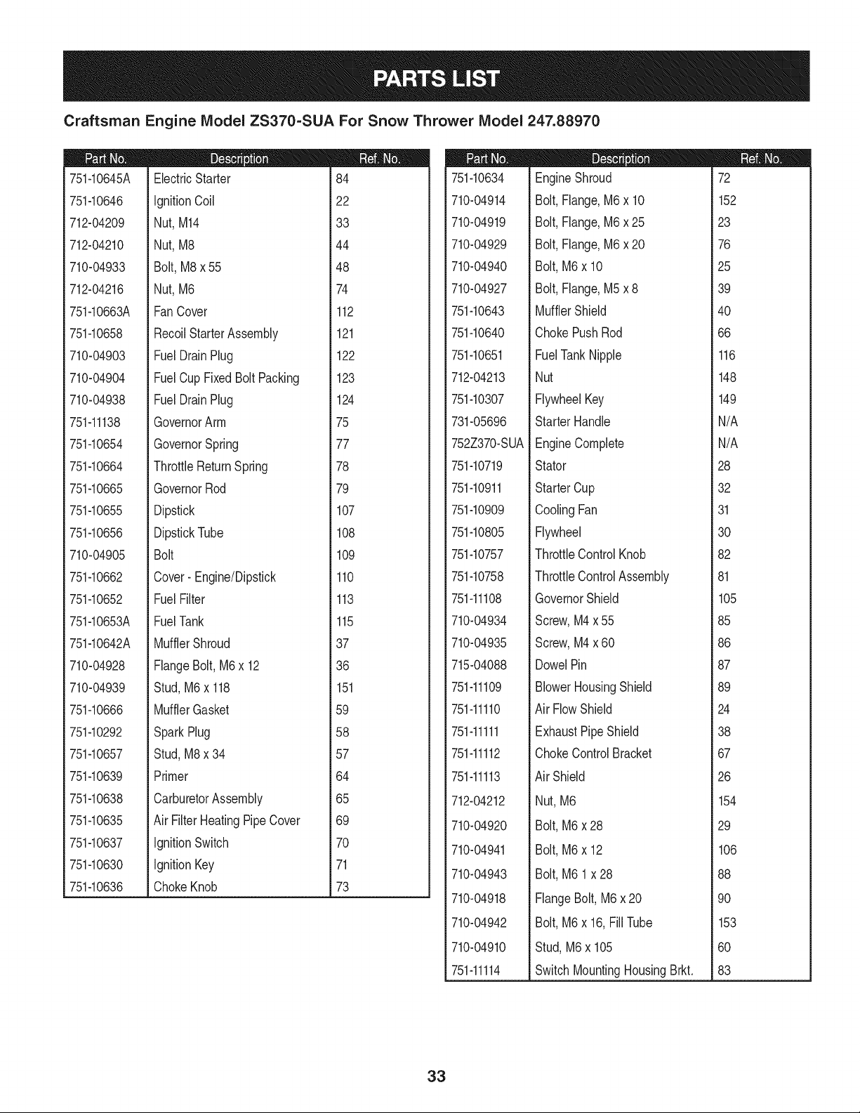
Craftsman Engine IViodel ZS370=SUA For Snow Thrower IViodel 247.88970
751-10645A
751-10646
712-04209
712-04210
710-04933
712-04216
751-10663A
751-10658
710-04903
710-04904
710-04938
751-11138
751-10654
751-10664
751-10665
751-10655
751-10656
710-04905
751-10662
751-10652
751-10653A
751-10642A
710-04928
710-04939
751-10666
751-10292
751-10657
751-10639
751-10638
751-10635
751-10637
751-10630
751-10636
D = O O
ElectricStarter
ignitionCoil
Nut, M14
Nut, M8
Bolt,M8 x 55
Nut, M6
Fan Cover
RecoilStarterAssembly
Fuel DrainPlug
FuelCup FixedBolt Packing
Fuel DrainPlug
GovernorArm
GovernorSpring
ThrottleReturnSpring
GovernorRod
Dipstick
DipstickTube
Bolt
Cover- Engine/Dipstick
Fuel Filter
FuelTank
MufflerShroud
FlangeBolt,M6x 12
Stud,M6x 118
MufflerGasket
SparkPlug
Stud,M8x 34
Primer
CarburetorAssembly
Air FilterHeatingPipeCover
ignitionSwitch
ignitionKey
ChokeKnob
84
22
33
44
48
74
112
121
122
123
124
75
77
78
79
107
108
109
110
113
115
37
36
151
59
58
57
64
65
69
70
71
73
751-10634
710-04914
710-04919
710-04929
710-04940
710-04927
751-10643
751-10640
751-10651
712-04213
751-10307
731-05696
752Z370-SUA
751-10719
751-10911
751-10909
751-10805
751-10757
751-10758
751-11108
710-04934
710-04935
715-04088
751-11109
751-11110
751-11111
751-11112
751-11113
712-04212
710-04920
710-04941
710-04943
710-04918
710-04942
710-04910
751-11114
I = O O
EngineShroud
Bolt,Flange,M6x 10
Bolt,Flange,M6x 25
Bolt,Flange,M6x 20
Bolt,M6x 10
Bolt,Flange,M5x 8
MufflerShield
ChokePushRod
FuelTankNipple
Nut
FlywheelKey
StarterHandle
EngineComplete
Stator
StarterCup
CoolingFan
Flywheel
ThrottleControlKnob
ThrottleControlAssembly
GovernorShield
Screw,M4x 55
Screw,M4x 60
DowelPin
BlowerHousingShield
Air FlowShield
ExhaustPipe Shield
ChokeControlBracket
Air Shield
Nut,M6
Bolt,M6x 28
Bolt,M6x 12
Bolt,M6 1x 28
FlangeBolt, M6 x 20
Bolt,M6x 16,Fill Tube
Stud,M6 x 105
SwitchMountingHousingBrkt.
72
152
23
76
25
39
40
66
116
148
149
N/A
N/A
28
32
31
30
82
81
105
85
86
87
89
24
38
67
26
154
29
106
88
90
153
60
83
33
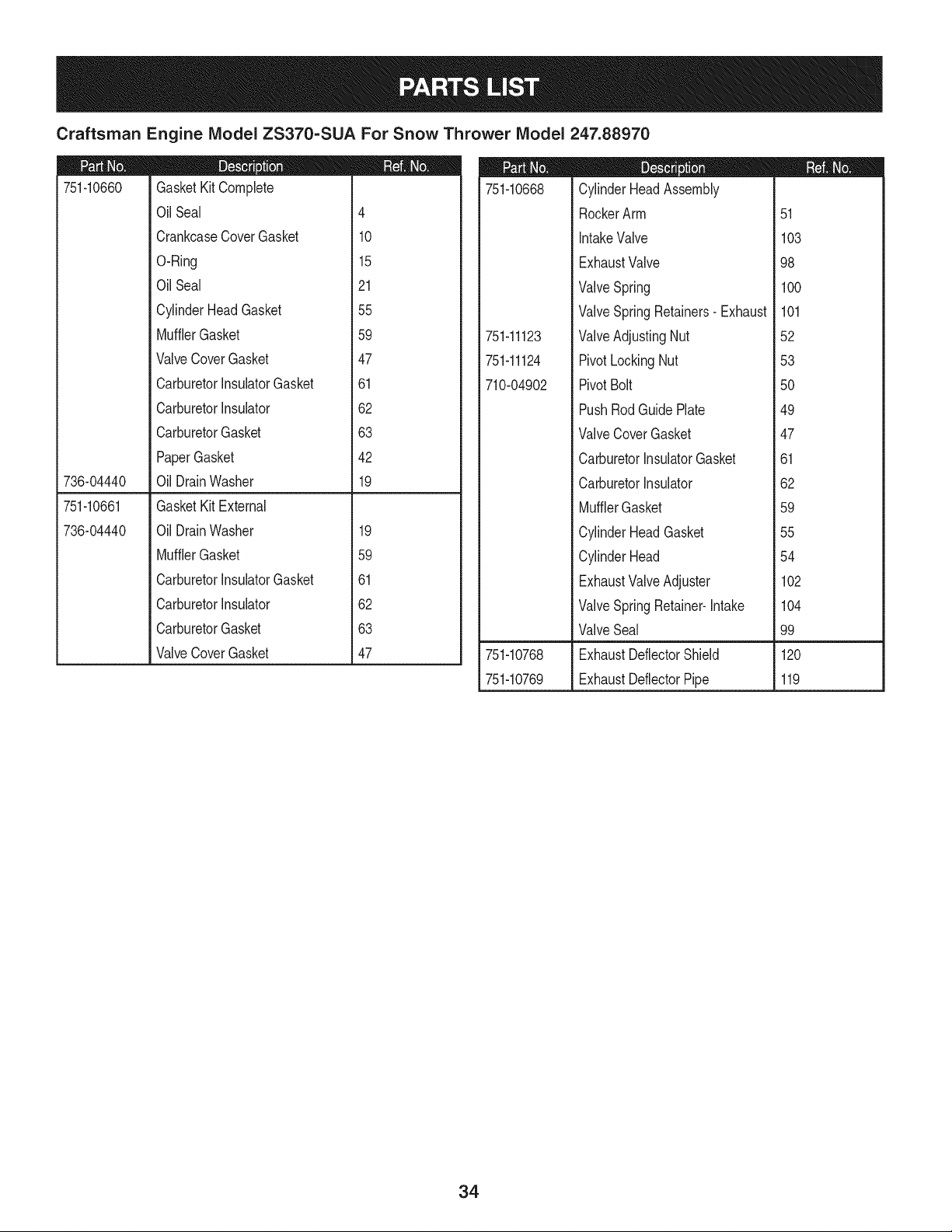
Craftsman Engine IViodel ZS370=SUA For Snow Thrower IViodel 247.88970
751-10660
736-04440
GasketKitComplete
Oil Seal
CrankcaseCoverGasket
O-Ring
Oil Seal
CylinderHeadGasket
MufflerGasket
ValveCoverGasket
CarburetorInsulatorGasket
CarburetorInsulator
CarburetorGasket
PaperGasket
Oil DrainWasher
4
10
15
21
55
59
47
61
62
63
42
19
751-10661
736-04440
GasketKit External
Oil DrainWasher
MufflerGasket
CarburetorInsulatorGasket
CarburetorInsulator
CarburetorGasket
ValveCoverGasket
19
59
61
62
63
47
751-10668
751-11123
751-11124
710-04902
D = O O
CylinderHeadAssembly
RockerArm
IntakeValve
ExhaustValve
ValveSpring
ValveSpringRetainers- Exhaust
ValveAdjustingNut
PivotLockingNut
PivotBolt
PushRodGuidePlate
ValveCoverGasket
CarburetorInsulatorGasket
CarburetorInsulator
MufflerGasket
CylinderHeadGasket
CylinderHead
ExhaustValveAdjuster
ValveSpringRetainer-Intake
ValveSeal
51
103
98
100
101
52
53
5O
49
47
61
62
59
55
54
102
104
99
751-10768 ExhaustDeflectorShield 120
751-10769 ExhaustDeflectorPipe 119
34
Craftsman Engine IViodel ZS370-SUA For Snow Thrower IViodel
|= 0 o
751-10659 Short BlockAssembly
714-04074
710-04907
736-04440
715-04092
715-04089
715-04090
710-04932
751-11101
CrankcaseComplete 17
Oil PipeReserve N/A
CrankcaseCover 5
Piston 93
PistonRingAssembly 95
PistonPin 94
PistonPinClip 92
ConnectingRodAssembly 91
Tappet 96
CamshaftAssembly 7
CarburetorinsulatorGasket 61
CrankshaftComplete 11
Carburetorinsulator 62
MufflerGasket 59
GovernorArm 16
GovernorShaftClip 14
GovernorKit 12
CrankcaseCoverGasket 10
CylinderHeadGasket 55
Oil DrainBolt 20
Oil DrainPlugWasher 19
DowelPin, 7 x 14 9
DowelPin,9 x 14 8
DowelPin 56
RadialBall Bearing 13
Bolt 1
Oil Seal 4
O-Ring- GovernorArm 15
Oil FillerPlug 2
O-Ring- Oil FillerPlug 3
ValveCoverGasket 47
Oil DrainPipe 18
RadialBall Bearing 6
Oil Seal 21
CrankcaseKit
GovernorSeal 150
RadialBall Bearing 13
O-ring- GovernorArm 15
CrankcaseComplete 17
Seal 21
247.88970
35
|= w o
751-11021 CarburetorKit Major
751-10641 OilDrainAssembly
OilDrain Pipe 18
710-04907 DrainBolt 20
751-10647 ValveKit
ExhaustValve 98
IntakeValve 103
751-10648 PushRodKit
PushRod 97
751-10649 FuelCapAssembly
FuelCapComplete 111
Packing( Gasket ) N/A
Clip ( GasketRetainer) N/A
751-10650 FuelLineKit
FuelLineClamp 117
FuelLine 118
751-10669 OilFill PlugAssembly
751-10644
751-11098
710-04932
751-11099
751-11063
OilFill Plug 2
O-Ring 3
MufflerAssemblyComplete
MufflerAssembly 41
ExhaustPipe 43
CrankcaseCoverKit
Bolt 1
OilFillerPlug 2
O-ring- Oil FillerPlug 3
OilSeal 4
CrankcaseCover 5
RadialBallBearing 6
CrankcaseCoverGasket 10
CrankshaftKit
OilSeal 4
RadialBallBearing 6
CrankshaftAssembly 11
RadialBallBearing 13
Seal 21
FlywheelKey 149
ValveCoverKit
ValveCover 46
ValveCoverGasket 47
MTDCONSUMERGROUPINC(MTD), the California Air Resources Board (CARB)
and the United States Environment Protection Agency (U. S. EPA)
Emission Control System Warranty Statement
(Owner's Defect Warranty Rights and Obligations)
EMISSIONCONTROLSYSTEMCOVERAGEIS APPLICABLETOCERTIFIEDENGINESPURCHASEDINCALIFORNIAIN2005ANDTHERE-
AFTER,WHICHARE USEDIN CALIFORNIA,ANDTO CERTIFIEDMODELYEAR2005ANDLATERENGINESWHICHARE PURCHASEDAND
USEDELSEWHEREINTHEUNITEDSTATES.
Californiaandelsewherein the UnitedStatesEmissionControlDefectsWarrantyCoverage
The CaliforniaAir ResourcesBoard(CARB),U. S. EPAandMTDarepleasedto explaintheemissionscontrolsystemwarrantyonyour modelyear
2006and latersmalloff-roadengine.In California,new smalloff-roadenginesmustbe designed,builtand equippedto meet theStatesanti-smog
standards.Elsewhereinthe UnitedStates,newnon-road,spark-ignitionenginescertifiedfor model2005and later,mustmeet similarstandardsset
forthby the U. S. EPA.MTDmustwarrantythe emissioncontrolsystemon yourenginefor the periodof timelistedbelow,providedtherehasbeen
noabuse,neglector impropermaintenanceof your smalloff-roadengine.
Youremissioncontrolsystemmay includepartssuch as the carburetor,fuel-injectionsystem,the ignitionsystem,andcatalyticconverter,fuel
tanks,fuel lines,fuel caps,valves,canisters,filters, vaporhoses,clamps,connectors,andotherassociatedemission-relatedcomponents.
Wherea warrantableconditionexists,MTDwill repairyoursmall off-roadengineat no cost to yourincludingdiagnosis,partsand labor.
MANUFACTURER'S WARRANTY COVERAGE:
Thisemissionscontrolsystemis warrantedfor twoyears.If anyemission-relatedpart on yourengine is defective,the part will berepairedor
replacedby MTD.
OWNER'S WARRANTY RESPONSIBILITIES:
As the smalloff-roadengineowner,youare responsibleforthe performanceof the requiredmaintenancelisted in your Owner'sManual.MTD
recommendsthatyou retainall yourreceiptscoveringmaintenanceson yoursmalloff-roadengine,but MTDcan not denywarrantysolelyfor the
lackof receiptsor foryour failureto ensurethe performanceto allscheduledmaintenance.
As the smalloff-roadengineowner,youshouldhoweverbeawarethat MTDmaydenyyour warrantycoverageif yoursmalloff-roadengineorpart
hasfaileddue toabuse,neglect,impropermaintenanceor unapprovedmodifications.
Youare responsiblefor presentingyour smalloff-roadengineto an AuthorizedMTDServiceDealeras soonas a problemexists.Thewarranted
repairsshouldbe completedin a reasonableamountof time,notto exceed30 days.
Ifyou haveanyquestionsregardingyourwarrantyrightsand responsibilities,you shouldcontacta MTDServiceRepresentativeat 1-800-800-7310
andaddressis MTDCONSUMERGROUP,RO.Box361131,ClevelandOH,44136-0019.
DEFECTS WARRANTY REQUIREMENTS FOR 1995 AND LATER SMALL OFF-ROAD ENGINES:
Thissectionappliesto 1995and later smalloff-roadengines.The warrantyperiodbeginson the datethe engineor equipmentis deliveredto an
ultimatepurchaser.
(a) GeneralEmissionsWarrantyCoverage
MTDmustwarrantto the ultimatepurchaserand eachsubsequentpurchaserthatthe engineis:
(1)Designed,built,and equippedsoas to conformwithallapplicableregulationsadoptedby the Air ResourcesBoardpursuantto its authorityin
Chapters1 and 2,Part 5, Division26of the Healthand SafetyCode;and
(2) Freefromdefectsin materialsandworkmanshipthat causethe failureof a warrantedpart to be identicalin all materialrespectsto the partas
describedin theenginemanufacturer'sapplicationfor certificationfora periodof two years.
(b)The warrantyon emissions-relatedpartswill be interpretedas follows:
(1)Anywarrantedpart that is not scheduledfor replacementas requiredmaintenancein the writteninstructionsrequiredby Subsection(c)
mustbewarrantedfor the warrantyperioddefinedin Subsection(a)(2). Ifany such partfails duringthe periodof warrantycoverage,it mustbe
repairedor replacedby MTDaccordingto Subsection(4)below.Anysuch part repairedor replacedunderthewarrantymustbewarrantedfor
the remainingwarrantyperiod.
(2)Any warrantedpartthat is scheduledonlyfor regularinspectioninthe writteninstructionsrequiredby Subsection(c) must bewarrantedfor
thewarrantyperioddefinedin Subsection(a)(2).A statementin such writteninstructionsto the effectof "repairor replaceas necessary"will
not reducethe periodof warrantycoverage.Anysuchpart repairedor replacedunderwarrantymustbe warrantedforthe remainingwarranty
period.
(3) Anywarrantedpartthat whichis scheduledfor replacementas requiredmaintenancein the writteninstructionsrequiredby Subsection(c)
mustbewarrantedfor the periodof timepriorto the first scheduledreplacementpointforthat part.Ifthe part failspriorto thefirst scheduled
replacement,the part mustbe repairedor replacedby MTDaccordingto Subsection(4) below.Any such part repairedor replacedunder
warrantymustbewarrantedfor the remainderof the periodpriorto the first scheduledreplacementpointfor the part.
(4)Repairorreplacementofanywarrantedpartunderthewarrantyprovisionsofthisarticlemustbeperformedatnochargetotheownerata
warrantystation.
(5)NotwithstandingtheprovisionsofSubsection(4)above,warrantyservicesorrepairsmustbeprovidedatallMTDdistributioncentersthat
arefranchisedtoservicethesubjectengines.
(6)Theownermustnotbechargedfordiagnosticlaborthatleadstothedeterminationthatawarrantedpartisinfactdefective,providedthat
suchdiagnosticworkisperformedatawarrantystation.
(7)Theenginemanufacturerisliablefordamagestootherenginecomponentsproximatelycausedbyafailureunderwarrantyofanywarranted
part.
(8)Throughouttheengine'swarrantyperioddefinedinSubsection(a)(2),MTDwillmaintainasupplyofwarrantedpartssufficienttomeetthe
expecteddemandforsuchparts.
(9)Anyreplacementpartmaybeusedintheperformanceofanywarrantymaintenanceorrepairsandmustbeprovidedwithoutchargetothe
owner.SuchusewillnotreducethewarrantyobligationsofMTD.
(10)Add-onormodifiedpartsthatarenotexemptedbytheAirResourcesBoardmaynotbeused.Theuseofanynon-exemptedadd-onor
modifiedpartsshallbegroundsfordisallowingawarrantyclaimmadeinaccordancewiththisarticle.Theenginemanufacturershallnotbe
liableunderthisarticletowarrantfailuresofwarrantedpartscausedbytheuseofnon-exemptedadd-onormodifiedpart.
(c) MTDwill includea copyof the followingemissionwarrantyparts list with each newengine,usingthoseportionsof the listapplicableto the
e__&gine.
(1)FuelMeteringSystem
• Coldstart enrichmentsystem(soft choke)
,,Carburetorandinternalparts
• Fuel Pump
• FuelTank
(2)Air InductionSystem
• Air cleaner
• Intakemanifold
(3) IgnitionSystem
• Sparkplug(s)
• MagnetoIgnitionSystem
(4)ExhaustSystem
Catalyticconverter
• SAI (Reedvalve)
(5) MiscellaneousItemsUsedin AboveSystem
Vacuum,temperature, position,time sensitivevalvesand switches
Connectorsandassemblies
(6) Evaporativecontrol
• Fuel Hosecertifiedfor ARBevaporativeemissionof 2006.
• Fuel HoseClamps
Tetheredfuel cap
Carboncanister
Vaporlines
GD0C-100174Rev.B
Look For Relevant Emissions Durability Period and
Air index information On Your Engine Emissions Label
Engines that are certified to meet the California Air Resources Board (CARB) Tier 2 Emission Standards must
display information regarding the Emissions Durability Period and the Air Index. Sears, Roebuck and Co., U.S.A.
makes this information available to the consumer on our emission labels.
The Emissions Durability Period describes the number of hours of actual running time for which the engine is
certified to be emissions compliant, assuming proper maintenance in accordance with the Operating & Mainte-
nance Instructions. The following categories are used:
Moderate: Engine is certified to be emission compliant for 125 hours of actual engine running time.
Intermediate: Engine is certified to be emission compliant for 250 hours of actual engine running time.
Extended: Engine is certified to be emission compliant for 500 hours of actual engine running time.
For example, a typical walk-behind lawn mower is used 20 to 25 hours per year. Therefore, the Emissions
Durability Period of an engine with an intermediate rating would equate to 10 to 12 years.
The Air Index is a calculated number describing the relative level of emissions for a specific engine family. The
lower the Air Index, the cleaner the engine. This information is displayed in graphical form on the emissions label.
After July 1,2000, Look For Emissions Compliance Period
On Engine Emissions Compliance Label
After July 1, 2000 certain Sears, Roebuck and Co., U.S.A. engines will be certified to meet the United States
Environmental Protection Agency (USEPA) Phase 2 emission standards. For Phase 2 certified engines, the Emis-
sions Compliance Period referred to on the Emissions Compliance label indicates the number of operating hours
for which the engine has been shown to meet Federal emission requirements.
For engines less than 225 cc displacement, Category C = 125 hours, B = 250 hours and A = 500 hours.
For engines of 225 cc or more, Category C = 250 hours, B = 500 hours and A = 1000 hours.
This is a generic representation of the emission label typically found on a certified engine.
FAMILYYBSXS.3192VA 274812
GDOC-100182Rev.A
38
Congratulationson makinga smartpurchase.YournewCraftsman@
productis designedandmanufacturedfor yearsof dependableopera-
tion.But likeall products,it mayrequirerepairfrom time to time.That's
whenhavinga RepairProtectionAgreementcansave youmoneyand
aggravation.
Here'swhatthe RepairProtectionAgreement*includes:
* Expert service byour 10,000professionalrepairspecialists
o Unlimitedserviceand no chargefor partsand laboron all
coveredrepairs
o Product replacementupto $1500if yourcoveredproductcan't be
fixed
• Discountof 10%from regularprice of serviceand relatedinstalled
partsnotcoveredby theagreement;also,10%off regularpriceof
preventivemaintenancecheck
• Fast help by phone- we call it RapidResolution- phonesupport
froma Searsrepresentative.Thinkof usas a "talkingowner's
manual."
Onceyou purchasethe Agreement,a simplephonecall is all thatit
takesfor youto scheduleservice.Youcan call anytimedayor night,or
schedulea serviceappointmentonline.
The RepairProtectionAgreementis a risk-freepurchase.If youcancel
for any reasonduringthe productwarrantyperiod,wewill providea full
refund.Or,a proratedrefundanytimeafterthe productwarrantyperiod
expires.Purchaseyour RepairProtectionAgreementtoday!
Somelimitationsand exclusionsapply. For pricesand additional
informationin the U.S.A.call 1-800-827-6655.
*Coverage in Canadavaries on some items. Forfull details call
Sears Canadaat 1-800-361-6665.
Sears Installation Service
ForSearsprofessionalinstallationof homeappliances,garagedoor
openers,waterheaters,and othermajorhomeitems,in the U.S.A.or
Canadacall 1-800-4-MY-HOME®.
39
Declaraci6n de garantia ............................ Pagina 39
Practicas operaci6n seguras ..................... Pagina 40
Montaje ...................................................... Pagina 44
Operaci6n .................................................. Pagina 48
Servicio y Mantenimiento .......................... Pagina 52
Almacenamiento fuera de temporada ....... Pagina 60
Soluci6n de problemas .............................. Pagina 61
Acuerdo de protecci6n para reparaciones .... Pagina 65
Etiquetas de seguridad .............................. Pagina 7
Lista de piezas ........................................... Pagina 26
NOmero de servicio ................................... Cubierta
posterior
GARANTiA LIMITADA CRAFTSMAN
Dos Ahos en Lanzador de Nieve
Cuandohechofuncionary mantenidosegOntodaslas instruccionessuministradas,si estelanzadorde nievefalla debidoa un defectoen mate-
rialo habilidaddentrode dosa_osde la fechao compra,vueltaello a algunaposici6ndebajadade Craftsmanautorizadaparala reparaci6n
libre.Paralaposici6nautorizadam_scercana,Ilame1-800-4MYHOME.
Estagaranfias61otendr_validezdurante90 dias si este productose utilizaen cualquiermomentopara fines comercialeso de alquiler.
Esta garantiacubreSOLOdefectos en material y habilidad.Sears no pagar_para:
• Losarficulosprescindiblesque se hacenIlevadospuestosduranteel uso normal,incluso,perono limitadospara patinarzapatos,platode
afeitado,esquilanalfileres,buj[a,filtrodeaire,cinturones,y filtro del aceite.
• Revisi6ndemantenimientoest_ndar,cambiosdeaceite,o puestasa punto.
• Reemplazode neum_ticoo reparaci6ncausadaporpinchazosdesdefuerade objetos,comou_as,espinas,tocones,o cristal.
• Neum_ticoo reemplazode ruedao reparaci6nque resultade ropanormal,accidente,u operaci6nimpropiao mantenimiento.
• Las reparacionesnecesariasdebidoal abusodeoperador,inclusoperono limitadoparada_arcausadoafectandoobjetosque doblanel
marcoo el cigOe_al,o el sobreexcesode velocidaddel motor.
• Reparacionesnecesariasdebidoa negligenciadel operador,incluyendoentre otros,da_osmec_nicoy el_ctricoocasionadopor un
almacenamientonoapropiado,falla por el usode aceitede grado y/o cantidadno apropiadao fallapor no dar mantenimientoal equipode
acuerdocon las instruccionescontenidasenel manualdeloperador.
• Limpiezao reparacionesal motor(sistemadecombustible)provocadaspor un combustiblecontaminadouoxidado(viejo).Engeneral,el
combustibledebeutilizarseen un perbdo no mayorde 30d[as a partirde su adquisici6n.
• Elempejoramientonormaly la ropade losfinesexteriores,o productoetiquetanel reemplazo.
Estagaranfias61otendrAvalidezmientrasel productose utiliceen los EstadosUnidos.
Estagaranfialeotorgaderechoslegalesespedficos,pero ustedpodr[agozarde otros derechosen raz6nde su lugarde residencia.
Sears, Roebuck and Co., HoffmanEstates, IL 60179
Tipode aceitedelmotor:
Capacidaddeaceitedel motor:
Capacidaddecombustible:
Bujfas:
Separaci6nde lasbujias:
5W-30
20 onzas
2.3 cuartos
Torch F6RTC (F6TC)
.020" a .030"
N_merode modelo ..........................................................
N_merode serie ..............................................................
Fechade compra .............................................................
Registrearriba el nOmerodel modelo,el nOmerode seriey lafecha
decompra
© Sears Brands,LLC
40
Lapresenciadeeste sirnboloindicaque setrata de instrucciones
irnportantesde seguridadquese debenrespetarparaevitar
poneren peligrosu seguridadpersonaly/o materialy lade otras
personas.Lea y siga todaslas instruccionesde este manualantes
de poneren funcionarnientoesta rn_.quina.Si no respetaestas
instruccionespodria provocarlesionespersonales.Cuandoveaeste
sirnbolo,ipresteatenci6na la advertencia!
PROPOSICI6N 65 DE CALIFORNIA
Elescapedel motordeeste producto,algunosde suscornponentes
y algunoscornponentesdelvehiculocontieneno liberan sustancias
quirnicasqueel estado de Californiaconsideraque puedenproducir
c_.ncer,defectosde nacirnientouotros problernasreproductivos.
Estarn_.quinarueconstruidapara seroperadade acuerdocon
las reglasde seguridadcontenidasen este manual.AI igualque
concualquiertipo deequipornotorizado,undescuidoo errorpor
partedeloperadorpuedeproducirlesionesgraves.Esta rn_.quina
es capazde arnputarrnanosy piesy dearrojarobjetoscon gran
fuerza.Deno respetarlas instruccionesde seguridadsiguientesse
puedenproducirlesionesgraveso larnuerte.
Su responsabilidad--Restrinja el usode estarn_.quina
rnotorizadaalas personasque lean,cornprendany respetenlas
advertenciase instruccionesqueaparecenen estemanualyen la
rn_.quina.
iGI.IARI)E ESTASINSTRUCCIONES!
CAPACITACION
• Lea,entienday curnplatodaslas instruccionesincluidasen
la rn_.quinayen los rnanualesantesdernontarlay utilizarla.
Guardeestemanualen un lugarseguroparaconsultasfuturasy
peri6dicas,asi cornopara solicitarrepuestos.
• Leael Manualdel Operadory sigatodaslas advertenciase
instruccionesde seguridad.Elfracasode hacerasi puedecausar
la heridaseriaal operadory/o personaspresentes.ParaIlarnada
depreguntas,1-800-659-5917.
• Farniliaricesecontodoslos controlesy con el usoadecuado
delos rnisrnos.Sepac6rnodetenerla rn_.quinay desactivarlos
controlesr_.pidarnente.
• No perrnitanuncaque los ni_osrnenoresde 14a_osutilicen
estarn_.quina.Los ni_osde 14a_osen adelantedeben leer y
entenderlas instruccionesde operaci6ny norrnasde seguridad
contenidasen este manual,yen la rn_.quinaydebenser entrena-
dosy supervisadosporun adulto.
• Nuncaperrnitaque los adultosoperenestarn_.quinasin recibir
antesla instrucci6napropiada.
• Losobjetosarrojadospor la rn_.quinapuedenproducirlesiones
graves.Planifiqueel patr6nenel queva air arrojandonievepara
evitarque ladescargade materialse realicehacialos carninos,
los observadores,etc.
• Mantengaa losobservadores,ayudantes,rnascotasy ni_ospor
Io rnenosa 75 piesde la rn_.quinarnientrasla rnisrnaest,.en
funcionarniento.Detengala rn_.quinasi alguienseacerca.
• Seaprecavidoparaevitarpatinarseo caerseespecialrnente
cuandoopera la rn_.quinaen reversa.
PR E PA RATIVO S
Inspeccionerninuciosarnenteel _.readondeutilizar_,el equipo.Saque
todoslos felpudos,peri6dicos,trineos,tablas,cablesy otros objetos
extra_oscon los que podriatropezaro que podrianser arrojadospor
labarrena/irnpulsor.
• Paraprotegerselosojos utilicesiernpreanteojoso antiparras
de seguridadrnientrasoperala rn_.quinao rnientrasla ajusta
o repara.Losobjetosarrojadosquerebotanpuedenproducir
lesionesocularesgraves.
• Noopere la rn_.quinasin la vestirnentaadecuadaparaestaral
airelibreen invierno.No utilicealhajas,bufandaslargasu otras
prendassueltasque podrianenredarseen las partesrn6viles.
Utiliceun calzadoespecialparasuperficiesresbaladizas.
• Useun prolongadory un tornacorrientede tres cables con
conexi6na tierraparatodaslas rn_.quinascon rnotoresde
encendidoel_ctrico.
• Ajustela alturade la caja deltornacorrientepara lirnpiarla grava
o las superficiescon piedrastrituradas.
• Desengranetodaslas palancasde controlantesde arrancarel
motor.
• Nuncaintenterealizarajustesrnientrasel motorest,. en rnarcha
exceptoen los casosespecificarnenterecornendadosen el
manualdel operador.
• Dejeque el motor y la rn_.quinase adaptena laternperatura
exteriorantesde cornenzara sacarla nieve.
41
Manejo seguro de la gasolina
Paraevitarlesionespersonales0 daSosrnaterialestengarnucho
cuidadocuandotrabajecon gasolina.Lagasolinaes surnarnente
inflarnabley susvaporespuedencausarexplosiones.Si se derrarna
gasolinaencirna0 sobrela ropa se puedelesionargravernenteya que
se puedeincendiar. L&vesela piel y c&rnbiesede ropade inrnediato.
• Utilices610los recipientesparagasolinaautorizados.
• Apaguetodoslos cigarrillos,cigarros,pipasy otras fuentesde
cornbusfi6n.
• Nuncacarguecombustibleen larn&quinaen unespaciocerrado.
• Nuncasaquela tapadelcombustibleni agreguecombustible
rnientrasel motorest&caliente0 en rnarcha.
• Dejequeel motorse enfriepor I0 rnenosdos rninutosantesde
volvera cargarcombustible.
• NuncaIleneenexcesoel dep6sitode combustible.Lleneel
tanquea no rn&sde 1/2pulgadapordebajode la basedelcuello
de Ilenadodejandoespaciopara la dilataci6ndeIcombustible.
• Vuelvaa colocarla tapade lagasoiinay aj_stelabien.
• Lirnpieel combustiblequese hayaderrarnadosobreel motory el
equipo.Trasladela rn&quinaa otra zona. Espere5 rninutosantes
deencenderel motor.
• Nuncaalrnacenela rn&quina0 el recipientede combustibleen
unespaciocerradodonde hayafuego,chispas0 luz piloto(por
ejernplo,hornos,calentadoresdeagua,calefactores,secadores
de ropa,etc.).
• Dejequela rn_.quinase enfrieporIo rnenos5 rninutosantesde
guardarla.
• NuncaIlenelos recipientesenel interiorde un vehiculoo carni6n
ocaja de rernolquecon recubrirnientospl_.sticos.Coloque
siernprelos recipientesenel pisoy lejosdel vehiculoantesde
Ilenarlos.
• Sies posible,retireel equipoa gasolinadel carni6no rernolque
y II_neloen el suelo.Si esto no es posible,Ileneel equipoen un
rernolquecon contenedorport_.til,en vez de desdeunaboquilla
dispensadoradegasolina.
• Mantengala boquilladispensadoraen contactocon el hordedel
dep6sitode combustibleo con la aberturadel recipienteen todo
rnornento,hastaterrninarla carga. No utiliceundispositivode
apertura/cierrede boquilla.
FUNCIONANIIENTO
• No pongalas rnanoso los piescercadelas piezasrotatorias,
en lacajade la barrena/ irnpulsoro en el rnontajedelcanalde
descarga.Hacercontactocon piezasgiratoriaspuederesultaren
laarnputaci6ndernanoso pies.
• La palancade controlde la barrena/ irnpulsores un dispositivo
de seguridad.Nuncaevitesu funcionarniento.De hacerlola
operaci6nde la rn_.quinaes riesgosay puedeocasionarlesiones.
• Las palancasde control debenfuncionarbienen arnbasdirec-
cionesy regresarautorn_.ticarnentea la posici6nde desengrane
cuandose lassuelta.
• Nuncaoperela rn_.quinasi falta un rnontajedelcanalo si el
rnisrnoest,.daSado.Mantengatodoslosdispositivosde seguri-
daden su lugaryen funcionarniento.
• Nuncaenciendael motor en espacioscerradoso en una zona
con pocaventilaci6n.El escapedel motorcontienernon6xidode
carbono,ungas inodoroy letal.
• Noutilice la rn_.quinabajo la influenciadel alcoholo las drogas.
• El silenciadory el motorse calientany puedencausarquernadu-
ras.Nolos toque. Mantengaa los niSosalejados.
• Seasurnarnenteprecavidocuandoopere la rn_.quinasobreuna
superficiecon gravaocuandola cruce.Mant_ngasealerta por si
se presentanpeligrosocultoso tr_.nsito.
• Tengacuidadocuandocarnbiede direcci6no cuandoopere la
rn_.quinaen pendientes.
• Planifiqueel patr6nenel queva a ir arrojandonieveparaevitar
que ladescargade materialse produzcahacialas ventanas,
las paredes,losautorn6viles,etc.y evitarasi posiblesdaSos
rnaterialeso lesionesproducidasporlos rebotes.
• Nuncadirija la descargahacialos niSos,los observadoreso las
rnascotasni dejequenadiese paredelantede la rn_.quina.
• Nosobrecarguela capacidadde la rn_.quinatratandode sacarla
nievernuyr_.pidarnente.
• Nuncaopereesta rn_.quinasin buenavisibilidado ilurninaci6n.
Siernpredebeestar segurode que est,. bien afirrnadoy su-
jetandofirrnernentelas rnanijas.Carnine,nuncacorra.
• Cortela corrientea la barrena/ irnpulsorcuandotransportela
rn_.quinao cuandola rnisrnano est,. en uso.
• Nuncaoperela rn_.quinaaalta velocidadde desplazarniento
sobresuperficiesresbaladizas.Mirehaciaabajoy haciaatr_.sy
tengacuidadocuandovaya rnarchaatr_.s.
• Si la rn_.quinacornenzaraa vibrarde rnaneraanorrnal,detengael
motor,desconecteel cablede labujiay p6ngalade rnaneraque
hagarnasacontra el motor.Inspeccionela rn_.quinarninuciosa-
rnenteparaver si est,.daSada.Reparetodoslos daSosantesde
encendery operarla rn_.quina.
• Desengranetodas las palancasde controly detengael motor
antesde dejar la posici6nde operaci6n(detr_.sdelas rnanijas).
Esperea que la barrena/ irnpulsorse detengapor cornpleto
antesde destaparel rnontajedel canalo realizarajustese
inspecciones.
• Nuncapongalas rnanosenlas aberturasdedescargao de
recolecci6n.Utilicesiernprela herrarnientadelirnpiezaquese
adjuntaparadestaparla aberturade descarga.Nodestapeel
rnontajedel canal rnientrasel motorest,.en funcionarniento.
Antesde destaparlo,apagueel motory perrnanezcadetr_.sde las
rnanijashastaque todaslas partesrn6vilesse hayandetenido.
• Uses61ounionesy accesoriosaprobadospor el fabricante(por
ejernplo,pesaspara las ruedas,cadenasparalos neurn_.ticos,
cabinas,etc.).
42
• Paraencenderel motor,jale de lacuerdalentarnentehastaque
sientaresistencia,luegojale r_.pidarnente.Elreplieguer_.pidode
la cuerdade arranque(tensi6nde retroceso)le jalar_,la rnanoy
el brazohaciael motorrn_.sr_.pidodeIo que usted puedesoltar.
El resultadopuedenserhuesosrotos,fracturas,hernatornaso
esguinces.
• Si se presentansituacionesque no est_.nprevistasen este
manual,seacuidadosoy use el sentidocornOn.P6ngaseen
contactocon Asistenciaal Clientepara solicitarayuday el
nornbredeldistribuidorde serviciorn_.scercano.
MANTENIMIENTO Y ALMACENAMIENTO
• Nuncaalterelos dispositivosde seguridad.Controleperi6dica-
rnenteque funcionencorrectarnente.Rernitasealas secciones
demantenirnientoy ajustede este manual.
• Antesde realizarla lirnpieza,repararo revisarla rn_.quina,
desengranetodas laspalancasde controly detengael motor.
Esperea quela barrena/ irnpulsorse detengaporcornpleto.
Desconecteel cablede la bujfay p6ngalohaciendornasacontra
el motorparaevitarquese enciendaaccidentalrnente.
• Controlefrecuenternentequetodos lospernosy tornillosest_n
bienajustadosparacornprobarquela rn_.quinase encuentra
encondicionessegurasde funcionarniento.Adern_.s,hagauna
inspecci6nvisual de la rn_.quinaparaverificarsi est,.da_ada.
• No carnbiela configuraci6ndel reguladordelmotorni acelere
dernasiadoel rnisrno.El reguladordel motorcontrolala velocidad
rn_.xirnaseguradefuncionarnientodelmotor.
• Las placasde raspadoy las zapatasantideslizantesquese
usancon la rn_.quinaquitanievese desgastany se da_an.
Paraprotegersu seguridad,verifiquefrecuenternentetodos los
cornponentesy reernpl_.celoss61ocon partesde los fabricantes
deequiposoriginales(OEM)."i Elusode piezasquenocurnplen
con lasespecificacionesdel equipooriginalpuederesultaren
rendirnientoinadecuadoadern_.sde poneren riesgola seguri-
dad!"
• Reviselas palancasde controlperi6dicarnenteparaverificar
queengraneny desengranenadecuadarnentey ajOstelossi es
necesario.Consultela secci6nde ajustesde este manualdel
operadorparaobtenerinstrucciones.
• Mantengao reernplacelasetiquetasde seguridade instrucciones
segQnseanecesario.
• Respetelas norrnasreferentesa ladisposici6ncorrectay las
reglarnentacionessobregasolina,aceite,etc. para protegerel
medicarnbiente.
• Antesdealrnacenarla rn_.quinaenci_ndalaunosrninutospara
sacarla nievequehayaquedadoen la rnisrnay paraevitarasi
quese congelela barrena/irnpulsor.
• SegOnla Cornisi6nde Seguridadde Productosparael Consu-
rnidorde los EstadosUnidos(CPSC)y la Agenciade Protecci6n
Arnbientalde los EstadosUnidos(EPA),este productotieneuna
vida Qtilmediade siete (7) a_os,660 horasdefuncionarniento.
AI finalizarlavida Otilmedia,adquierauna rn_.quinanuevao
hagainspeccionaranualrnente_sta por un distribuidorde servicio
autorizadoparacerciorarsede quetodoslos sisternasrnec_.nicos
y deseguridadfuncionancorrectarnentey no tienenexcesivo
desgaste.Si no Iohace,puedenproducirseaccidentes,lesiones
o rnuerte
• Nuncaalrnacenela rn_.quinao el recipientede combustibleen un
espaciocerradodondehayafuego,chispaso luz pilotocornopor
ejernplo,calentadoresde agua,hornos,secadoresde ropa,etc.
• Consultesiernpreel manualdeloperadorparaobtener
instruccionesadecuadasparaelalrnacenarnientofuerade
ternporadaVerifiquefrecuenternentelaIfneade combustible,el
tanque,el tap6n,y losaccesoriosbuscandorajaduraso perdidas.
Reernplacede ser necesario.
• Nod_ arranqueal motorsi noest,. labujiade encendido.
NO MODIFIQUE EL MOTOR
Paraevitarlesionesgraveso larnuerte,no rnodifiqueel motorbajo
ningunacircunstancia.Si carnbiala configuraci6ndel reguladorel
motorpuededescontrolarsey operara velocidadesinseguras.Nunca
carnbielaconfiguraci6nde f_.bricadel reguladordel motor.
AVISO REFERIDO A EMISIONES
Losrnotoresqueest&ncertificadosy curnplencon las regulaciones
de ernisionesfederalesEPAy de Californiapara SORE(Equipos
peque_ostodoterreno)est_.ncertificadosparaoperarcon gasolina
cornOnsinplornoy puedenincluirlossiguientessisternasde control
de ernisiones:Modificaci6nde motor(EM) y catalizadorde tresvias
(TWO)si est_.nequipadosde esa rnanera.
GUARDACHISPAS
Estarn&quinaest,. equipadacon unmotorde cornbusti6ninternay
nodebe ser utilizadaen o cercade unterrenoagrestecubiertopor
bosque,rnalezaso hierbaexceptosi el sisternade escapedelmotor
est,.equipadocon unarnortiguadorde chispasquecurnplaconlas
leyeslocaleso estatalescorrespondientes,en caso de haberlas.
Sise utilizaun arnortiguadorde chispasel operadorIo debernantener
en condicionesde usoadecuadas.Enel Estadode Californialas
rnedidasanteriorrnenternencionadassonexigidaspor ley (Arficulo
4442del C6digode RecursosPOblicosde California).Es posible
queexistanleyessirnilaresenotros estados.Lasleyesfederalesse
aplicanenterritoriosfederales.
Puedeconseguirelarnortiguadorde chispasparael silenciadora
travesde sudistribuidorautorizadode rnotoreso poni_ndoseen
contactocon eldepartarnentodeservicios.
43
SiMBOLOS DE SEGURIDAD
Estap_ginadescribelossirnbolosy figurasde seguridadinternacionalesquepuedenaparecerenesteproducto.Leael manualdel operador
)araobtenerla inforrnaci6nterrninadasobreseguridad,reunirse,operaci6ny rnantenimientoy reparaci6n.
i
i
LEAELMANUAL DELOPERADOR(S)
Lea,entienda, y siga todas lasinstrucciones en el manual (es)antes de intentar reunirse y funcionar.
LA ADVERTENCIA -- PLATOS ROTATORIOS
Guarde manos de entrada y aperturas de la descarga mientras la m_iquina corre. Alli ellos hacen para
girar platos dentro.
LA ADVERTENCIA-- LAMINAS ROTATIVAS
Guarde manos de entrada y aperturas de descarga mientras la m_iquina corre. Alli hacen girar I_iminas
dentro.
LA ADVERTENCIA -- TALADRO ROTATIVO
No ponga manos o pies cerca del giro de partes, en el alojamiento de taladro/aspa o asamblea de
tolva. Contacto con las partes rotativas puede amputar manos y pies.
OBJETOS LANZADOS POR ADVERTENCIA
Esta m_iquina puede recoger y lanzar y objetos que pueden causar la herida personal seria.
GASOLINA DE ADVERTENCIA ESINFLAMABLE
Permita que el motor se enfrie al menos dos minutos antes del reabastecimiento de combustible.
ADVERTENCIA -- MONOXIDO DE CARBONO
Nunca dirijas un motor dentro o en un _irea mal ventilada. Los gases de combusti6n de motor
contienen el mon6xido de carbono, un gas inodoro y mortal.
ADVERTENCIA- ELECTROCHOQUE
No use eljuez de salida el_ctrico del motor en la Iluvia.
44
NOTA:las referenciasal lado derechoo y ciertosde la rnAquina
quitanievesedeterrninandesdela parteposteriorde la unidaden
posici6ndeoperaci6n(perrnaneciendodirectarnentedetrAsdela
rnAquinaquitanieve,rnirandohaciael panelde la rnanija).
EXTRACCI6N DE LA UNIDAD DE LA CAJA
1. Corte lasesquinasde la cajade cart6ny exti_ndalaen el piso
Quitey descartetodoslos insertosde ernpaque.
2. Saquela rnAquinaquitanievede la caja.
3. AsegQresede vaciarcornpletarnentela cajaantesde tirarla.
MONTAJE
1. Observeel Areainferiortraserade la rnAquinaquitanievepara
asegurarsede quearnboscablesest_n alineadoscon las gufas
rotatoriasantes de girar la rnanijahaciaarriba.
a. Coloquela palancade carnbiosenla posici6ndeavance(F)
6.
b. Tire haciaarribay haciaatrAsde la rnanijasuperior,tal y
cornose rnuestraen la figura 1.Cuandoustedlevantael
mangohaciaarriba,asegQreseque arnbosfinalesdel cable
decentro soncolocadoscorrectarnenteen los soportes.
Alineela rnanijasuperiorcon la rnanijainferior.
c. Aprietelas perillasrnanualesque sujetanla rnanijasuperior
a la rnanijainferior.Retirey descartetodoslas bandasde
plAstico,si Las hubiera.Unicarnentese utilizanpara el
ernpaque.
2. Retirela tuercade rnariposay el tornillohexagonaldel rnontajede
controldelcanal, y el pasadordehorquillay el pasadorde
chavetade la rn_nsulade soportedelcanal.Veala figura2. SitQe
el rnontajedel canal (rnirandohaciadelante)sobrela basedel
rnisrno.
3. SitQecontroldel canalen una posici6ncentrada.Veala figura 1.
4. Ubiqueel rnontajedel canalsobrela basedel rnisrnoy asegure
el rnontajede control del canala la rn_nsulade soportedelcanal
rnedianteel pasadorde horquillay el pasadorde chaveta
retiradosanteriorrnente.Vea la figura3.
f
t
k_ j
Figura2
Figura1
Figura3
5. Terrninedeasegurarelrnontajedecontroldelcanalalarn_nsula
desoportedelcanalconlatuercadernariposayeltornillo
hexagonalretiradosanteriorrnente.Vealafigura4.
6. Controlequetodosloscablesest_nadecuadarnentedirigidosa
travesdelagufadecablesdelapartesuperiordelmotor.Veala
figura5.
7. Elprolongadorparaelarrancadorel_ctricoseajustarnediante
unauni6ndecablealaparteposteriordelacajadelabarrena
paraelernbarque.Cortelauni6ndecableyrefirelaantesdeoperar
arn_.quinaquitanieve.
CONFIGURACI6N
Pasador de cuchilla
Enel panelde instrurnentosde pl_.sticohayorificiosparael
almacenarnientoconvenientedel pasadorde cuchilla.Veala figura6.
Consultela seciondeservicioy rnantenirnientopararn_.sinforrnacidn
encuantoel reernplazodelpasadorde cuchilla.
i i
f
Figura5
Figura4
Figura6
46
Herramienta de Lirnpieza del Canal
Hayuna herrarnientade lirnpiezadel canal iajustadaa la parte
superiorde lacaja de la barrenacon un pasadorde ensarnNado.
Veala figura7. Laherrarnientaest&diseSadaparalirnpiarel hielo y la
nievedelrnontajede un canal.Esteproductose sujeta rnedianteuna
uni6nde cableen laf&brica.Corte la uni6n de cableantes de operar
la rnAquinaquitanieve.
Nuncausesus rnanospara liberar un rnontajede canaltapado.Ap-
agueel motory perrnanezcadetr_.sde las rnanijashasta que todas
las partes rn6vilesse hayandetenidoantesde utilizarla herrarnienta
de lirnpiezaparalirnpiarel rnontajedel canal.
Presi6n de los neumaticos
Antesde cualquieroperaci6n,cornpruebela presi6nde arnbos
neurn_.ticosy reduzcalarnisrnaa entre15psiy 20psi.
NOTA:Sila presi6nde los neurn_.ticosno es igualen arnbosneurn_.ti-
cos,es posibleque la unidadno siga unatrayectoriarectay quela
placade raspadose desgastede forrnadespareja.
Herrarnienta de
Lira _iezadel Canal
Figura7
AJUSTES
Zapatas antideslizantes
Laszapatasantideslizantesde la rn_.quinaquitanieveseajustanpara
arribaen f_.bricaparaelenvio.Si Iodesea,puedeajustarlashacia
abajoantesde hacerfuncionarla rn_.quinaquitanieve.
Nose recorniendaqueopereesta rn_.quinaquitanievesobregrava,
ya que es posiblequela rn_.quinaquitanievetome la gravasueltay
la barrenalaexpulse,Io cual podriacausarlesionespersonaleso
da_arla rn_.quinaquitanieve.
• Sideseaquitarnieveal rasdel suelo,elevern_.slaszapatas
antideslizantesenla cajade la barrena.
• Uselas posicionesmediao bajacuandola superficieque desee
lirnpiarseadespareja,cornouncarninode grava.
f
NOTA:Sitienequeusar la rn_.quinaquitanievesobregrava,rnantenga X,.
lazapataantideslizanteen la posici6nrn_.selevadapara Iograruna
separaci6nrn_.xirnaentreel pisoy laplacade raspado.
Figura8
Paraajustarlaszapatasantideslizantes:
1. Aflojelas cuatrostuercashexagonales(dosencada lado)y los
pernosdel carro. Muevalas zapatasantideslizantesa la posici6n
deseada.Veala figura8.
2. Cornpruebeque toda la superficieinferiorde laszapatas
antideslizantesest_contrael sueloparaevitarundesgaste
desparejode los rnisrnos.
3. Vuelvaa ajustarbien lastuercasy lospernos.
47
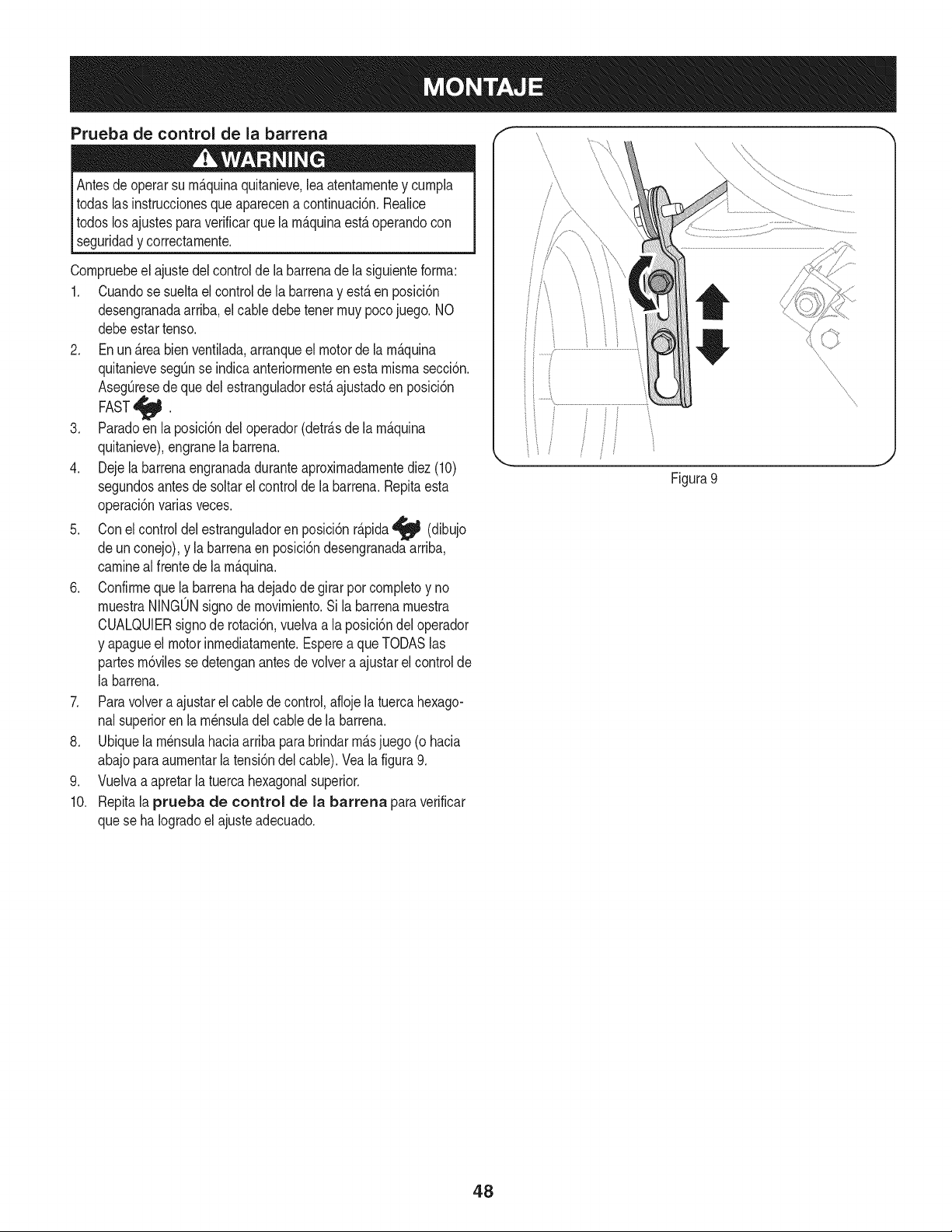
Prueba de control de la barrena
Antesde operarsu rn_.quinaquitanieve,leaatentarnentey curnpla
todaslasinstruccionesqueaparecena continuaci6n.Realice
todoslosajustesparaverificarque la rn_.quinaest,.operandocon
[ segurdad y correctarnente.
Cornpruebeel ajustedel controldela barrenadela siguienteforrna:
1. Cuandose sueltael controlde la barrenay est,.en posici6n
desengranadaarriba,elcabledebetenetrnuypocojuego. NO
debeestartenso.
2. En un _.reabienventilada,arranqueel motorde la rn_.quina
quitanievesegQnse indicaanteriorrnenteen esta rnisrnasecci6n.
AsegQresede quedelestranguladorest,. ajustadoen posici6n
FAST_ .
3. Paradoen la posicidndel operador(detrfisde la rnfiquina
quitanieve),engranela barrena.
4. Dejela barrenaengranadaduranteaproxirnadarnentediez(10)
segundosantesde soltarel controlde la barrena.Repitaesta
operaci6nvariasveces.
5. Conel controldel estranguladoren posici6nr_.pida'_ (dibujo
deun conejo),y la barrenaen posici6ndesengranadaarriba,
carnineal frente de la rn_.quina.
6. Confirrneque la barrenaha dejadode girar por cornpletoy no
rnuestraNINGONsignodernovirniento.Si labarrenarnuestra
CUALQUIERsignode rotaci6n,vuelvaa la posici6ndel operador
y apagueel motorinrnediatarnente.Esperea queTODASlas
partesrn6vilessedetenganantesde volvera ajustarel control de
la barrena.
7. Paravolvera ajustarel cablede control,aflojela tuercahexago-
nalsuperioren la rn_nsuladel cablede la barrena.
8. Ubiquela rn_nsulahaciaarribapara brindarrn_,sjuego (o hacia
abajoparaaurnentarla tensi6ndelcable).Veala figura9.
9. Vuelvaa apretarla tuercahexagonalsuperior.
10. Repitala prueba de control de la barrena paraverificar
quese ha Iogradoel ajusteadecuado.
f
/\
Figura 9
48
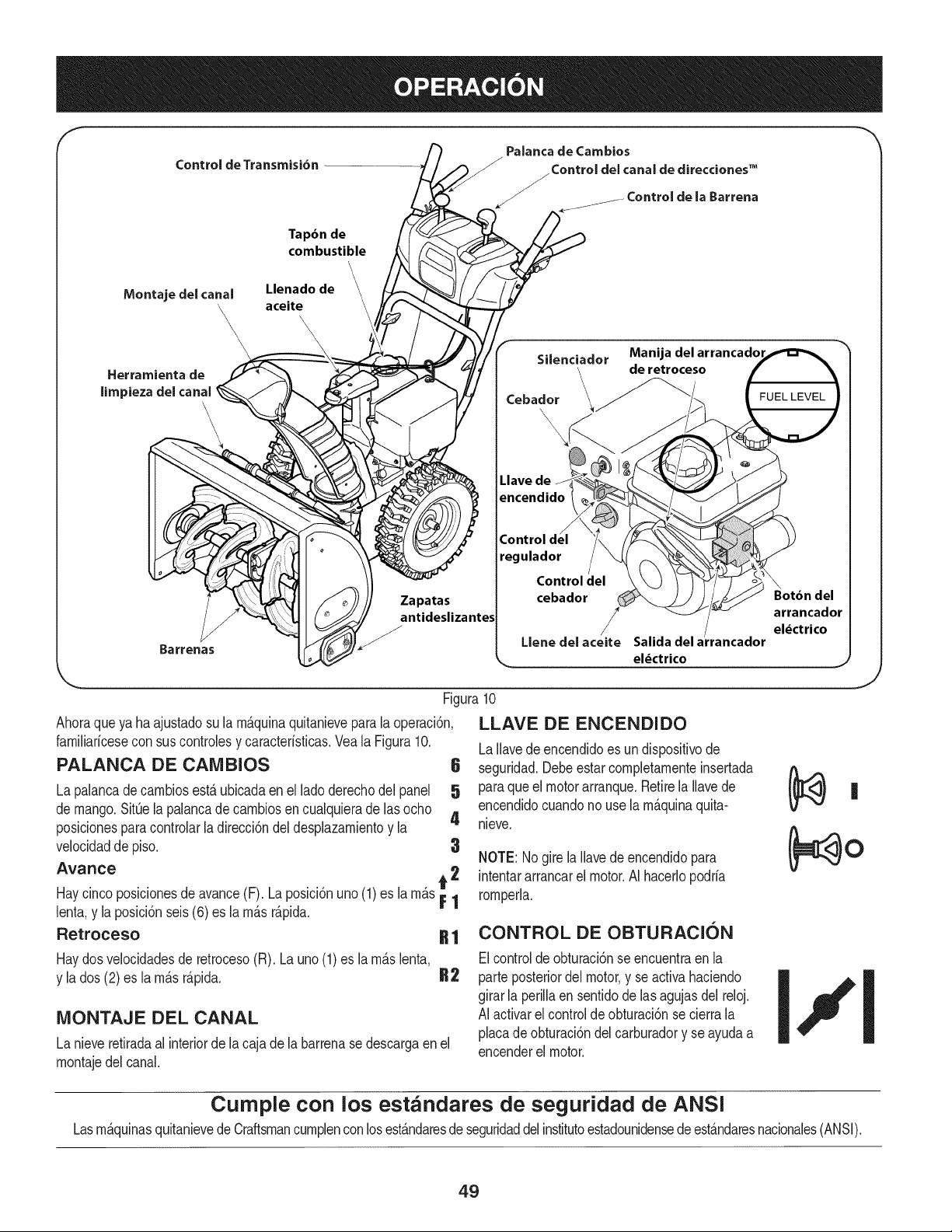
f
Control de Transmisi6n
Palanca de Cambios
J
_Control del canal de direcciones TM
Control de la Barrena
Tapbn de
combustible
\
Montaje del canal Llenado de
aceite \
\\\_\ '\\ \
, \
\
Herramienta de
limpieza del canal
Barrenas
Zapatas
antideslizantes
Silenciador Manija del arrancador
\ de retroceso
Cebador \___ FUEL LEVEL
L.lave de
encendido
regulador
Control del
cebador
Llene del aceite
Botbn del
arrancador
/
el_ctrico
Salidadel a_rancador
el_ctrico
Figura10
Ahoraqueya haajustadosu la rn_.quinaquitanieveparala operaci6n,
farniliaricesecon sus controlesy caracteristicas.Veala Figura10.
PALANCA DE CAMBIOS 6
La palancade carnbiosest,. ubicadaen el lado derechodel panel 5
de mango.SitQela palancade carnbiosen cualquierade las ocho
4
posicionesparacontrolarla direcci6ndel desplazarnientoy la
velocidadde piso. 3
Avarice A 2
Haycincoposicionesdeavance(F). La posici6nuno(1)es la rn_s_ |
lent& y la posici6nseis(6) es la rn_sr_pida.
Retroceso R 1
Haydosvelocidadesde retroceso(R). La uno (1) es la rn_.slenta,
y la dos (2)es la rn_.sr_.pida. R2
MONTAJE DEL CANAL
La nieveretiradaal interiorde la cajade la barrenase descargaen el
rnontajedel canal.
LLAVE DE ENCENDIDO
LaIlavede encendidoes undispositivode
seguridad.Debeestar cornpletarnenteinsertada
paraque el motorarranque.Retirela Ilavede
encendidocuandono use larn_.quinaquita-
nieve.
NOTE: Nogire la Ilavede encendidopara
intentararrancarel motor.AI hacerlopodria
rornperla.
CONTROL DE OBTURACION
Elcontroldeobturaci6nse encuentraen la
parte posteriordel motor,y se activahaciendo
girarla perillaen sentidodelas agujasdel reloj.
AI activarel controlde obturaci6nse cierrala
placade obturaci6ndelcarburadory se ayudaa
encenderel motor.
.J
Cumple con los estandares de seguridad de ANSi
LasrnAquinasquitanievede CraftsmancurnplenconlosestAndaresde seguridaddel institutoestadounidensedeestAndaresnacionales(ANSI).
49
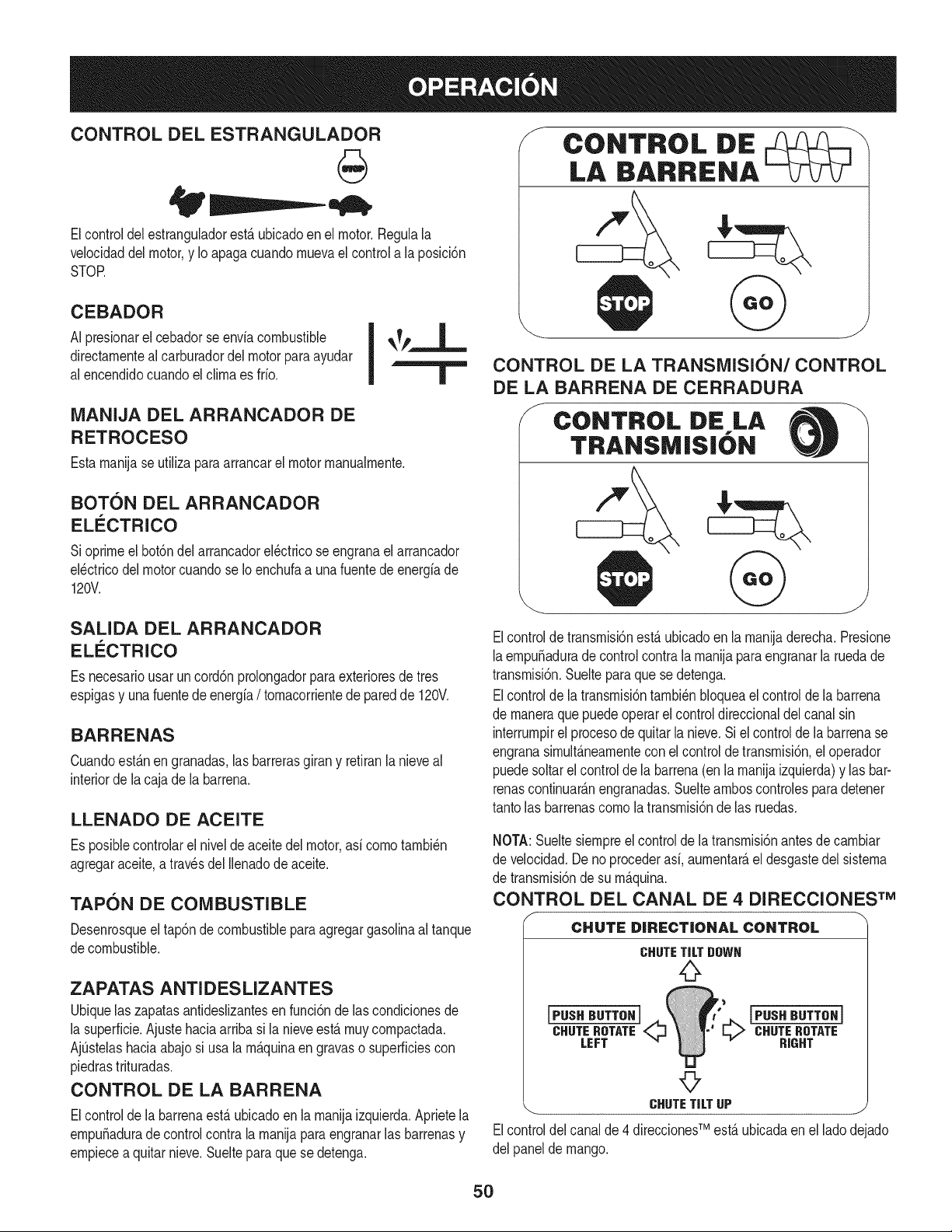
CONTROL DEL ESTRANGULADOR
Elcontrol del estrangulador estfi ubicado en el motor. Negula la
velocidad del motor,y Io apaga cuando mueva el control a la posicidn
STOP.
CEBADOR
| II
AI presionarel cebadorse enviacombustible | _k_p_.,L.
directamentealcarburadordel motor paraayudar I
al encendidocuandoel clima es frio. |
MANIJA DEL ARRANCADOR DE
RETROCESO
Estamanilase utilizaparaarrancarel motormanualmente.
BOTON DEL ARRANCADOR
ELECTRICO
Sioprimeel bot6ndelarrancadorel_ctricose engranael arrancador
el_ctricodel motorcuandose Ioenchufaa unafuente de energiade
120V.
SALIDA DEL ARRANCADOR
ELECTRICO
Es necesariousar uncord6nprolongadorparaexterioresde tres
espigasy una fuentede energia/ tomacorrientede paredde 120V.
BARRENAS
Cuandoest_nen granadas,las barrerasgirany retiranlanieveal
interiorde lacaja de la barrena.
LLENADO DE ACEITE
Es posiNecontrolarel nivelde aceitedel motor,asi como tambi_n
agregaraceite,a travesdel Ilenadode aceite.
TAPON DE COMBUSTIBLE
Desenrosqueel tap6ndecombustibleparaagregargasolinaaltanque
decombustible.
ZAPATAS ANTI DES LIZANTES
Ubiquelas zapatasantideslizantesen funci6nde lascondicionesde
la superficie.Ajustehaciaarribasi la nieveest,. muy compactada.
AjQstelashaciaabajosi usala m&quinaen gravaso superficiescon
piedrastrituradas.
CONTROL DE LA BARRENA
Elcontrolde la barrenaestaubicadoenla manilaizquierda.Aprietela
empuSadurade controlcontra la manilaparaengranarlas barrenasy
empiecea quitarnieve.Suelteparaque se detenga.
CONTROL DIE
LA BARRENA
J
CONTROL DE LA TRANSMISION/CONTROL
DE LA BARRENA DE CERRADURA
J CONTROL DiE LA
TRANSM|S|ON
Elcontroldetransmisi6nest&ubicadoen la maniladerecha.Presione
laempuSaduradecontrolcontralamanilaparaengranarla ruedade
transmisi6n.Sueltepara que se detenga.
Elcontrolde latransmisi6ntambi_nbloqueael controlde la barrena
de maneraque puedeoperar el controldireccionaldel canalsin
interrumpirel procesode quitarla nieve.Siel controlde labarrenase
engranasimult&neamentecon elcontroldetransmisidn,el operador
puedesoltarel controlde labarrena(en la manilaizquierda)y lasbar-
renascontinuar_.nengranadas.Suelteamboscontrolesparadetener
tantolas barrenascomola transmisi6nde las ruedas.
NOTA:Sueltesiempreel controlde latransmisi6nantesde cambiar
de velocidad.Deno procederasi, aumentar&el desgastedel sistema
de transmisi6nde su m_.quina.
CONTROL DEL CANAL DE 4 DIRECCIONES TM
CHUTE D|RECT|ONAL CONTROL
CHUTE TiLT DOWH
0
[PUSHBUTTSHJ
CHUTEROTATE
LEFT
[PUSH BUTTSH]
_ CHUTE ROTATE
RIGHT
©
CHUTETiLTUP j
TM
Elcontroldelcanalde 4 direcciones est&ubicadaen el Jadodejado
del panelde mango.
5O
• Carnbiarladirecci6nen la cual lanievees lanzada,apret6nel
bot6nen lapalancade rnandoy pivotela palancade rnandoa la
derechao a la izquierda.
• Paracarnbiarel _.ngulo/distanciaqu_nievees lanzada,gire la
palancade rnandoavanzadao haciaatr_.s.
HERRAIVIIENTA DE LIMPIEZA
lNunca usesus rnanospara liberar un rnontajede canaltapado.AntesI
de destaparlo,apagueel motory perrnanezcadetr_.sde lasrnanijas I
hastaque todas laspartes rn6vilesse hayandetenido, j
La herrarnientade lirnpiezadel canal est,.ajustadaconvenienternente
a la parteposteriorde lacaja de la barrenacon unpasadorde ensarn-
blado.Si seacurnulannievey hieloen el canal dedescargadurante
la operaci6n,procedacornose indicaa continuaci6nparalirnpiarde
rnanerasegurael rnontajedel canaly la aberturadelcanal:
1. Suelteelcontrolde la barrenay elcontroldela transrnisi6n.
2. Paradetenerel motorsaquela Ilavede encendido.
3. Saquela herrarnientade lirnpiezadel pasadorquela ajustaa la
parteposteriordela cajade la barrena.
4. Use el extrernoconforrnade pala de la herrarnientade lirnpieza
paradesplazary recogerla nievey el hielo que se forrnaroncerca
delconjuntodel canal.
5. Vuelvaa ajustarla herrarnientade lirnpiezaal pasadordeen-
sarnbladoubicadoen la parteposteriorde la cajade la barrena,
insertede nuevola Ilavede encendidoy enciendael motorde la
rn_.quinaquitanieve.
6. Paradoen la posici6ndel operador(detr_.sde la rn_.quinaquita-
nieve),engraneel controldelabarrenaduranteunossegundospara
elirninarlanieveo el hieloque hayanquedadoenelconjuntodel
canal.
ANTES DE ENCENDER EL MOTOR
Lea,cornprenday sigatodaslas instruccionesy advertenciasque
aparecenen la rn_.quinayen estemanualantesde operarla.
Aceite
El motorse envi6conaceite en el motor.Controleel nivelde aceite
antesde cadaoperaci6npara asegurarsede que hayaaceite
suficienteen el motor.Paraobtenerrn_.sinstrucciones,rernitasea los
pasosqueaparecenen la p_.gina52.
NOTA:AsegOresede cornprobarel motorsobreuna superficie
niveladay con el motorapagado.
1. Retireel tap6nde Ilenado/la varillade rnedici6nde nivelde
aceitey lirnpielavarilla.
2. Inserteel tap6n/la varillade rnedici6nenel cuellode Ilenadode
aceite,perono la atornille.
3. Extraigael tap6nde Ilenado/ lavarillade niveldeaceite.Si
el niveles bajo,agregueaceite (5W-30,con unaclasificaci6n
minimade SF/SG)lentarnentehastaqueel registromarqueentre
nivelalto (H) y bajo(L).
NOTA:NoIo Ileneen exceso.El Ilenadoexcesivodeaceitepuede
hacerque el motorgenere hurno,quecuestearrancarloo fallasen la
bujia.
4. Vuelvaa colocarel tap6n/la varillade aceitey ajusteconfirrneza
antesde arrancarel motor.
Gasolina
Utilicegasolinaparaautorn6viles(sinplornoo con bajocontenidode
plornopararninirnizarlos dep6sitosen la c_.rnarade cornbusti6n)con
unoctanajerninirnode 87.Se puedeusargasolinacon hastaun 10%
de etanolo un 15%de MTBE(eter rnefilicoterciario-bufilico).Nunca
useunarnezclade aceitey gasolinani gasolinasucia.Eviteque se
introduzcasuciedad,polvoo agua en el tanquedecombustible.NO
utilicegasolinaE85.
• Carguecombustibleen un _.reabienventiladay conel motor
apagado.Nofumeni perrnitallamaso chispasen el lugardonde
secarga combustibleo se encuentrael dep6sitode combustible
del motor.
• No Ileneen excesoel tanquede combustible.Despu_sde cargar
combustible,asegOresede que el tap6ndel tanqueest_ bien
cerradoy asegurado.
• Tengacuidadode no derrarnarcombustibleal realizarla recarga.
Elcombustiblederrarnadoo susvaporesse puedenincendiar.
Sise derrarnacombustible,asegQresedeque el _.reaest_seca
antesde arrancarel motor.
• Eviteel contactorepetidoo prolongadocon la pielo inhalarlos
)ores.
Tengaextrernocuidadocuandornanipulegasolina.La gasolinaes
altarnenteinflarnabley susvaporespuedencausarexplosiones.
Nuncaagreguecombustiblea la rn_.quinaen interioreso rnientras
lel motorest,.calienteoen funcionarniento.Apaguelos cigarrillos,
lcigarros,pipasy otras fuentesde cornbusti6n.
1. Antesdesacar la tapa paracargarcombustible,lirnpiealrededor.
2. Enel tanquede combustiblehay unindicadorde nivel.Lleneel
tanquehastaIlegaral nivelde combustibledel indicador.Vea la
Figura10.Tengacuidadopara no Ilenarel dep6sitoen exceso.
ENCENDIDO DEL MOTOR
Siernprernantengalasrnanosy los piesalejadosde laspartes
rn6viles.No utilicefluidoscornprirnidosparaarrancar.Losvapores
soninfiarnables.
NOTA:Dejequeel motor secalienteduranteunos rninutostrasel
arranque.Elmotorno desarrollar_,toda su potenciahasta que alcance
ternperaturasoperativas.
1. AsegQresede queelcontroldela barrenay el controldela
transrnisi6nest_n en posici6ndesengranada(sin presionar).
2. InsertelaIlavede encendidoen la ranura.AsegOresede que
entre a presi6nen sulugar.No intentegirarla Ilave.
NOTA:Elmotornopuedearrancarsi la Ilaveno est,. cornpletarnente
insertadaenel interruptordeencendido.
51
Arn 2. Muevalapalancadel cebadorhasta laposid6n ON IJl
Elarrancadorel_ctricoopcionalest,. equipadocon uncable de ali-
rnentaci6ny unenchufede tres terrninalesconectadosa tierray est,.
dise_adoparaoperar concorrientedorn_sticade 120voltios.Debe
set utilizadocon un recept_.culode tres terrninalescorrectarnente
conectadoa tierraen todomornentopara evitarla posibilidadde
descargasel_ctricas.Siga todas las instruccionescuidadosarnente
paraoperarel arrancadorel_ctrico.NOutiliceel arrancadorel_ctrico
bajola Iluvia.
Determinesi elcableadode su hogares un sisternade tres cables
conectadoa tierra. Consultecon unelectricistarnatriculadosi no est,.
seguro.
Si cuentacon un recept_.culode tresterrninales,siga los siguientes
pasos.Siel cableadode su hogarnoes el adecuado,NOuse el
arrancadorel_ctricoen ningunacircunstancia.
1. Conecteel prolongadora la salidasituadaenla superficiedel
motor.Conecteel otroextrernodel prolongadoren un recept_.culo
de CAcon conexi6na tierrade tres terrninalesde 120voltios,en
un_.reabienventilada.
2. Muevala palancade controldel reguladora la posici6nFAST
(r_.pido,representadaporunaliebre). _j_
3. Muevala palancadel cebadorhastala posici6nON I,J¢l
(encendidoconel motoren frio). Si el motoryaest,.caliente,
ubiqueel cebadoren la posici6nOFE
4. Presioneel cebadortresa cinco(3-5)veces,asegur_.ndosede
cubrirel orificiodeventilaci6ncuandoIohaga.Si el motorest,.
caliente,presioneel cebadoruna solavez. Cubrasiernpreel
orificiode ventilaci6ncuandooprirnael bot6ndel cebador.Si
hacefrio puede resultarnecesariorepetirel cebado.
5. Presioneel bot6ndel arrancadorparaarrancarel motor.Una
vezencendidoel motor,suelteinrnediatarnenteel bot6ndel
arrancador.Elarrancadorel_ctricotiene unaprotecci6ncontra
sobrecargat_rrnica;el sisternase apagar_,transitoriarnentepara
perrnitirquese enfrieel arrancadorencaso que se sobrecargue
el arrancadorel_ctrico.
6. Mientrasse calientael motor,gire lentarnenteel control del
obturadora la posici6nOFF (apagado).Si el motorse detiene,
vuelvaa encenderlo,h_.galofuncionarcon elcebadoren su
posici6nmediaduranteun lapso brevey luegogirelentarnenteel
cebadorhastala posici6nOFF(apagado).
7. Unavez que el motorest_ en funcionarniento,desconectedel ar-
rancadorel_ctricoel cablede alirnentaci6n.Paradesconectarlo,
desenchufesiernpreel extrernoque est,. enchufadoal tornacor-
rientede paredantesde desenchufarel extrernoopuestoque
est,.conectadoal motor.
Arrancador de retroceso
Notire de la rnanijadel arrancadorrnientrasel motorest,. en rnarcha.1
1. Muevala palancade controldel regula_ra la posici6nFAST
(r_.pido,representadaporunaliebre).'_
(encendidocon el motorenfrio). Siel motorya est,. caliente,
ubiqueelcebadoren la posici6nOFE
3. Presioneel cebadortresa cinco(3-5)veces,asegur_.ndosede
cubrirelorificiodeventilaci6ncuandoIo haga.Siel motorest,.
caliente,presioneel cebadoruna solavez.Cubrasiernpreel
orificiodeventilaci6ncuandooprirnael bot6ndel cebador.Si
hacefrio puede resultarnecesariorepetirel cebado.
4. Jalesuavernentela rnanijadel arrancadorhastaque cornience
aofrecerresistencia,luegoj_Jelar_.pidarnentey con fuerzapara
superarla cornpresi6n.No sueltela rnanijani perrnitaque se
desenganche.Vuelvala cuerdaLENTAMENTEa su posici6n
original.De sernecesario,repitaestepaso.
5. Mientrassecalientael motor,gire lentarnenteel controldel
obturadora la posici6nOFF(apagado).Si el motor sedetiene,
vuelvaa encenderlo,h_.galofuncionarcon el cebadoren su
posici6nmediaduranteun lapsobrevey luegogire lentarnenteel
Paraevitarqueel motorfuncionesin control,nuncaIo deje sin
vigilanciarnientrasest,.en rnarcha.Apagueel motorluegode usarlo
__saque a avede encenddo
DETENCION DEL MOTOR
Dejeencendidoel motordurantealgunosrninutosantesde detenerlo
paraperrnitirquese sequela hurnedaden el rnisrno.
1. Muevael controldel reguladora la posici6ndetenci6n.
2. Retirela Ilavede encendido.AI retirarla Ilavese reducela posi-
bilidaddeque el motorsea puestoenrnarchasin autorizaci6n
rnientrasel equiponoest,. en uso. Guardela Ilaveen un lugar
seguro.Elmotorno puede arrancarsin la Ilavede encendido.
3. Elirninela hurnedadde loscontrolesdel motor.
PROCEDIMIENTO PARA ENGRANAR LA
TRANSMISION
1. Conel controldel estranguladoren posici6nr_.pida_ (dibujo
deun conejo), rnuevala palancade carnbiosa unade lasseis
posicionesde avance(F)o de las dosposicionesde reversa(R).
Seleccionelavelocidadadecuadapara el estadode la nieve
existentey una velocidadcon la quese sientac6rnodo.
2. Aprieteel controlde la transrnisi6ncontrala rnanijaderecha,y la
rn_.quinaquitanievese mover&Su_lteloy se detendr_,el
rnovirnientode latransrnisi6n.
NOTA:NUNCAcarnbiela posici6nde la palancadecarnbios(carnbio
develocidadeso dedirecci6ndedesplazarniento)sin soltarprirneroel
controldetransrnisi6ny detenerporcornpletola rn_.quinaquitanieve.
Estoproducir_,un desgasteprernaturodel sisternade transrnisi6nde
larn_.quinaquitanieve.
PROCEDIMIENTO PARA ENGRANAR LAS
BARRENAS
1. Aprieteel controlde la barrenacontrala rnanijay las barrenas
rotar_.n.Su_ltelay las barrenassedetendr_.n.
52
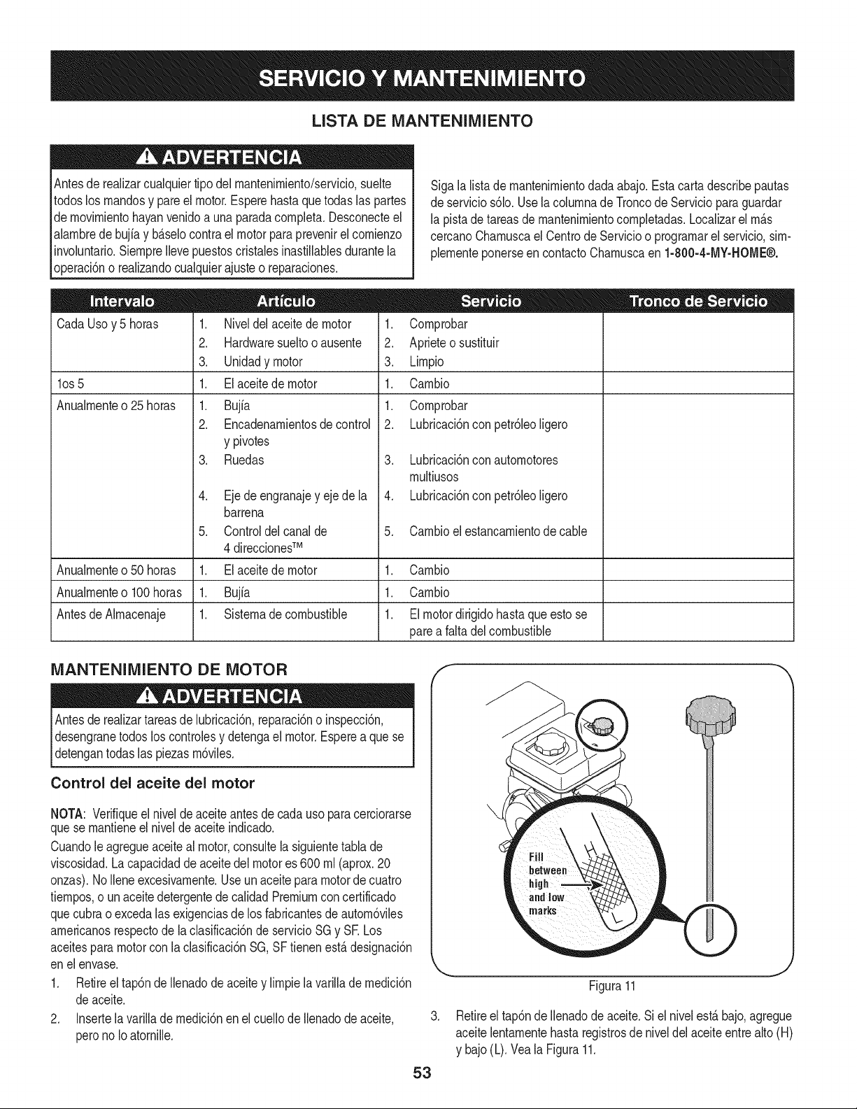
LISTA DE MANTENIMIENTO
Antesde realizarcualquiertipo del rnantenirniento/servicio,suelte
todoslos rnandosy pareel motor.Esperehastaque todas las partes
de rnovirnientohayanvenidoa una paradacornpleta.Desconecteel
alarnbrede bujiay b_.selocontrael motorpara prevenirel cornienzo
invohntario.SiernpreIlevepuestoscristalesinastillablesdurantela
operaci6no realizandocualquierajusteo reparaciones.
CadaUsoy 5 horas
los 5
Anualrnente o 25 horas
Sigala listade rnantenirnientodadaabajo.Esta carta describepautas
de servicios61o.Usela cohrnnade Troncode Servicioparaguardar
la pistadetareasde rnantenirnientocornpletadas.Localizarel rn_.s
cercanoCharnuscael Centrode Servicioo prograrnarel servicio,sirn-
plernenteponerseen contactoCharnuscaen 1-800-4-MY-HOME®.
1. Niveldel aceitede motor
2. Hardwaresueltooausente
3. Unidadymotor
1. El aceitede motor
1. Bujfa
2. Encadenarnientosde control
y pivotes
3. Ruedas
.
5.
Ejedeengranajey eje de la
barrena
Controldelcanalde
4 direccionesTM
Elaceitede motor
Bujfa
Sisternadecombustible
1. Cornprobar
2. Aprieteo sustituir
3. Lirnpio
1. Carnbio
1. Cornprobar
2. Lubricaci6nconpetr61eoligero
3. Lubricaci6nconautornotores
rnultiusos
4. Lubricaci6nconpetr61eoligero
5. Carnbioel estancarnientode cable
Anualrnenteo50 horas 1. 1. Carnbio
Anualrnenteo100horas 1. 1. Carnbio
Antesde Alrnacenaje 1. 1. Elmotordirigidohasta que esto se
parea faltadel combustible
MANTENIMIENTO DE MOTOR
Antesde realizartareasde lubricaci6n,reparaci6no inspecci6n,
desengranetodos loscontrolesy detengael motor.Esperea que se
detengantodas las piezasrn6viles.
Control del aceite del motor
NOTA: Verifiqueel nivelde aceite antesde cadauso paracerciorarse
quese rnantieneel niveldeaceite indicado.
Cuandole agregueaceiteal motor,consultela siguientetabla de
viscosidad.La capacidadde aceite del motores 600 rnl(aprox.20
onzas).NoIleneexcesivarnente.Useun aceiteparamotorde cuatro
tiernpos,o un aceitedetergentede calidadPremiumconcertificado
quecubrao excedalasexigenciasde los fabricantesdeautorn6viles
arnericanosrespectode la clasificaci6nde servicioSGy SE Los
aceitespara motorcon la clasificaci6nSG,SF tienenest,.designaci6n
enel envase.
1. Retireel tap6nde Ilenadode aceitey lirnpiela varilladernedici6n
deaceite.
2. Insertela varillade rnedici6nenel cuellode Ilenadodeaceite,
perono Io atornille.
f
.
53
J
Figura11
Retireel tap6nde Ilenadodeaceite.Si el nivelest,.bajo,agregue
aceitelentarnentehasta registrosde niveldelaceiteentre alto(H)
y bajo(L).Veala Figura11.
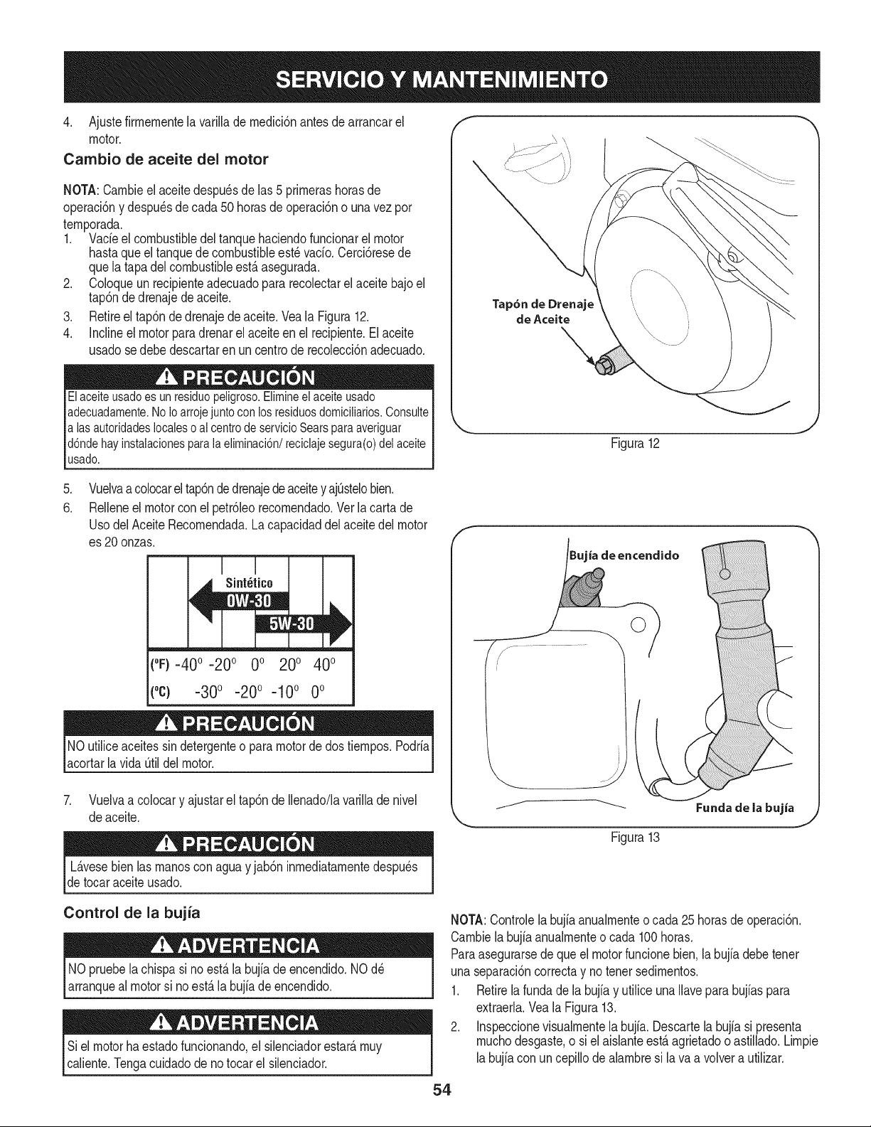
4. Ajustefirmementelavarillademedici6nantesdearrancarel
motor.
Cambio de aceite del motor
NOTA:Cambieelaceitedespu_sdelas5primerashorasde
operaci6nydespu_sdecada50horasdeoperaci6nounavezpor
temporada.
1. Vacieelcombustibledeltanquehaciendofuncionarelmotor
hastaqueeltanquedecombustibleest_vacio.Cerci6resede
quelatapadelcombustibleest,.asegurada.
2. Coloqueunrecipienteadecuadopararecolectarelaceitebajoel
tap6ndedrenajedeaceite.
3. Retireeltap6ndedrenajedeaceite.VealaFigura12.
4. Inclineelmotorparadrenarelaceiteenelrecipiente.Elaceite
usadosedebedescartarenuncentroderecolecci6nadecuado.
Elaceiteusadoesunresiduopeligroso.Elimineelaceiteusado
adecuadamente.NoIoarrojejuntoconlosresiduosdomiciliarios.Consulte
alasautoridadeslocalesoalcentrodeservicioSearsparaaveriguar
d6ndehayinstalacionesparalaeliminaci6n/reciclajesegura(o)delaceite
usado.
Tap6n de Drenaje
de Aceite
Figura12
.
6.
Vuelvaa colocarel tap6nde drenajede aceitey ajOstelobien.
ReNeneel motorconel petr61eorecomendado.Ver la carta de
UsodelAceite Recomendada.La capacidaddel aceitedel motor
es 20 onzas.
(0F)-40o-20 o 0o 200 400
(oc) -300 -200 -100 0o
NO utiliceaceitessindetergenteo para motorde dos tiempos.Podria
acortarla vida Otildel motor.
7. Vuelvaa colocary ajustarel tap6nde Ilenado/lavarillade nivel
de aceite.
L_.vesebienlas manosconagua y jab6ninmediatamentedespu_s
detocar aceiteusado.
ia de encendido
j._ ......................
Control de la bujia
NOpruebela chispasi noest,.la bujiadeencendido.NOd_
arranqueal motorsi no est,. la bujia de encendido.
Siel motorhaestadofuncionando,el silenciadorestate,muy
caliente.Tengacuidadode no tocar el silenciador.
NOTA:Controlelabujia anualmenteo cada 25horasdeoperaci6n.
Cambiela bujiaanualmenteo cada 100horas.
Paraasegurarsede queel motorfuncionebien.la bujiadebetenet
unaseparaci6ncorrectay no tenet sedimentos.
1. Retirela fundade la bujiay utilice unaNavepara bujiaspara
extraerla.Vea la Figura13.
2. Inspeccionevisualmentela bujfa. Descartela bujia si presenta
muchodesgaste,o siel aisianteest,.agrietadooastillado.Limpie
labujiacon uncepillodealambresi la va a volvera utilizar.
54
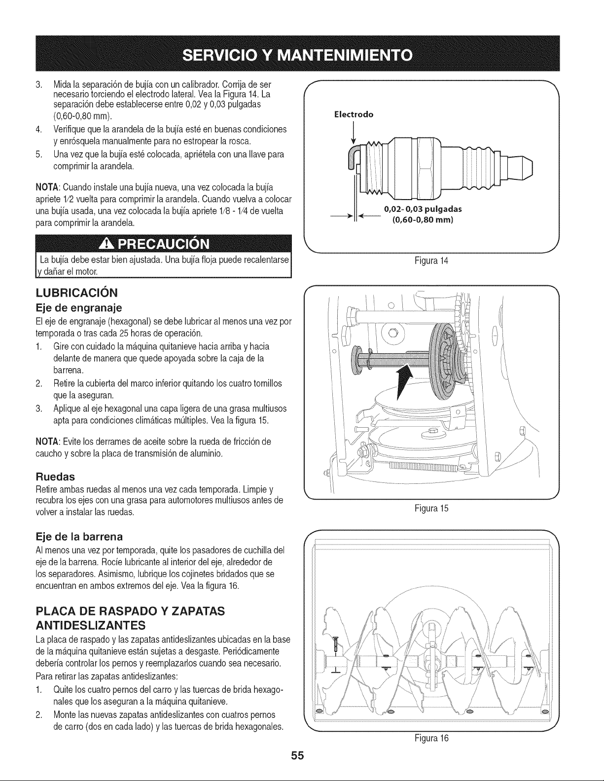
3. Midala separaci6nde bujia con uncalibrador.Corrijade ser
necesariotorciendoel electrodolateral.Veala Figura14.La
separaci6ndebeestablecerseentre0,02y 0,03 pulgadas
(0,60-0,80ram).
4. Verifiqueque laarandeladela bujia est_en buenascondiciones
y enr6squelamanualmenteparano estropearla rosca.
5. Unavez que la bujfaest_ colocada,apri_telacon unaIlavepara
comprimirlaarandela.
NOTA:Cuandoinstaieuna bujia nueva,una vez colocadala bujia
apriete1/2vueltaparacomprimirla arandela.Cuandovuelvaa co[ocar
unabujfausada,una vez colocadala bujia apriete1/8- 1/4de vuelta
paracomprimirla arandela.
da_arel motor.
LUBRICACION
Eje de engranaje
Eleje deengranaje(hexagonal)se debelubricaral menosunavez por
temporadaotras cada25horasde operaci6n.
1. Gire concuidadola m_.quinaquitanievehaciaarribay hacia
delantede maneraque quedeapoyadasobrela cajade la
barrena.
2. Retirela cubiertadel marcoinferiorquitandolos cuatrotornillos
quela aseguran.
3. Apliqueal eje hexagonalunacapaligera de una grasa multiusos
aptaparacondicionesclim_.ticasm_ltiples.Vealafigura 15.
NOTA:Evitelos derramesde aceite sobrela ruedade fricci6nde
cauchoy sobrela placade transmisi6nde aluminio.
Ruedas
Retireambasruedasal menosuna vezcada temporada.Limpiey
recubralos ejescon una grasapara automotoresmultiusosantesde
volvera instalarlas ruedas.
f
Electrodo
0,02= 0,03 pulgadas
(0,60=0,80 ram)
Figura14
J
Figura15
Eje de la barrena
AI menosuna vezportemporada,quitelos pasadoresde cuchilladel
ejede labarrena.Rode lubricanteal interiordel eje,alrededorde
los separadores.Asimismo,lubriquelos cojinetesbridadosquese
encuentranen ambosextremosdel eje.Vealafigura 16.
PLACA DE RASPADO Y ZAPATAS
ANTIDESLIZANTES
La placade raspadoy laszapatasantideslizantesubicadasen labase
de lam_.quinaquitanieveest_.nsujetasa desgaste.Peri6dicamente
deberiacontrolarlos pernosy reemplazarloscuandosea necesario.
Pararetirarlas zapatasantideslizantes:
1. Quitelos cuatropernosdel carroy las tuercasde bridahexago-
nalesquelos asegurana lam_.quinaquitanieve.
2. Montelas nuevaszapatasantideslizantesconcuatrospernos
decarro (dosencada lado)y las tuercasde bridahexagonales.
Figura16
55
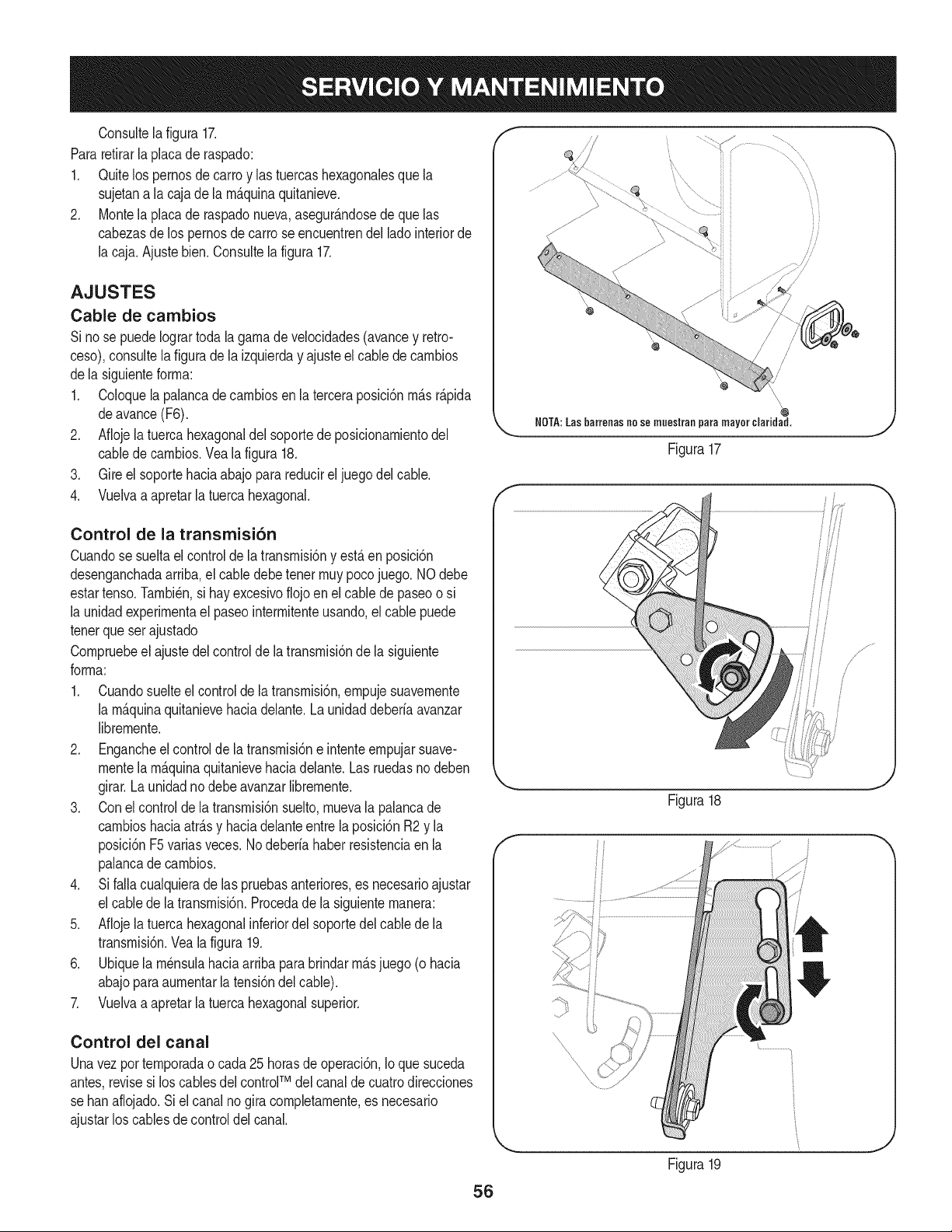
Consultela figura 17.
Pararetirarla placade raspado:
1. Quitelos pernosde carte y las tuercashexagonalesque la
sujetana lacaja dela m&quinaquitanieve.
2. Montela placade raspadonueva,asegur&ndosede que las
cabezasde lospernosdecarte seencuentrendel ladeinteriorde
la caja.Ajustebien.Consultela figura 17.
AJUSTES
Cable de cambios
Si nose puedeIogrartodala gamade velocidades(avancey retro-
ceso),consultela figuradela izquierday ajusteel cablede cambios
dela siguienteforma:
1. Coloquela palancade cambiosen la terceraposici6nm&sr&pida
deavance(F6).
2. Aflojela tuerca hexagonaldel soportede posicionamientodel
cabledecambios.Vea la figura 18.
3. Gire el soportehaciaabajo para reducirel juegodel cable.
4. Vuelvaa apretarla tuercahexagonal.
f
HOTA:Las harreoas no so muostran para mayor claridad.
Figura17
Control de la transmisi6n
Cuandose sueltael controlde latransmisi6ny est&en posici6n
desenganchadaarriba,el cabledebetenet muypocojuego. NOdebe
estartense.Tambi_n,si hay excesivoflojoen el cable depaseoo si
la unidadexperimentael paseointermitenteusando,elcable puede
tenerqueser ajustado
Compruebeel ajustedel controldela transmisi6nde la siguiente
forma:
1. Cuandosuelteel controlde la transmisi6n,empujesuavemente
la m&quinaquitanievehaciadelante.Launidaddeberfaavanzar
libremente.
2. Engancheel controlde latransmisi6ne intenteempujarsuave-
mentela m&quinaquitanievehaciadelante.Las ruedasno deben
girar.Launidadnodebe avanzarlibremente.
3. Conel controlde la transmisi6nsuelto,muevala palancade
cambioshaciaatrasy haciadelanteentre laposici6nR2 y la
posici6nF5variasveces.Nodeberfahaberresistenciaen la
palancade cambios.
4. Si falla cualquierade las pruebasanteriores,es necesarioajustar
el cabledela transmisi6n.Procedade la siguientemanera:
5. Aflojela tuerca hexagonalinferiordel soportedel cablede la
transmisi6n.Veala figura 19.
6. Ubiquela m_nsulahaciaarribapara brindarm&sjuego (o hacia
abajoparaaumentarla tensi6ndel cable).
7. Vuelvaa apretarla tuercahexagonalsuperior.
Control del canal
Unavezpertemporadao cada25 horasde operaci6n,Io quesuceda
antes,revisesi los cablesdelcontroFMdelcanalde cuatrodirecciones
se ban aflojado.Si el canal nogira completamente,es necesario
ajustarlos cablesdecontroldelcanal.
f
Figura18
Figura19
56
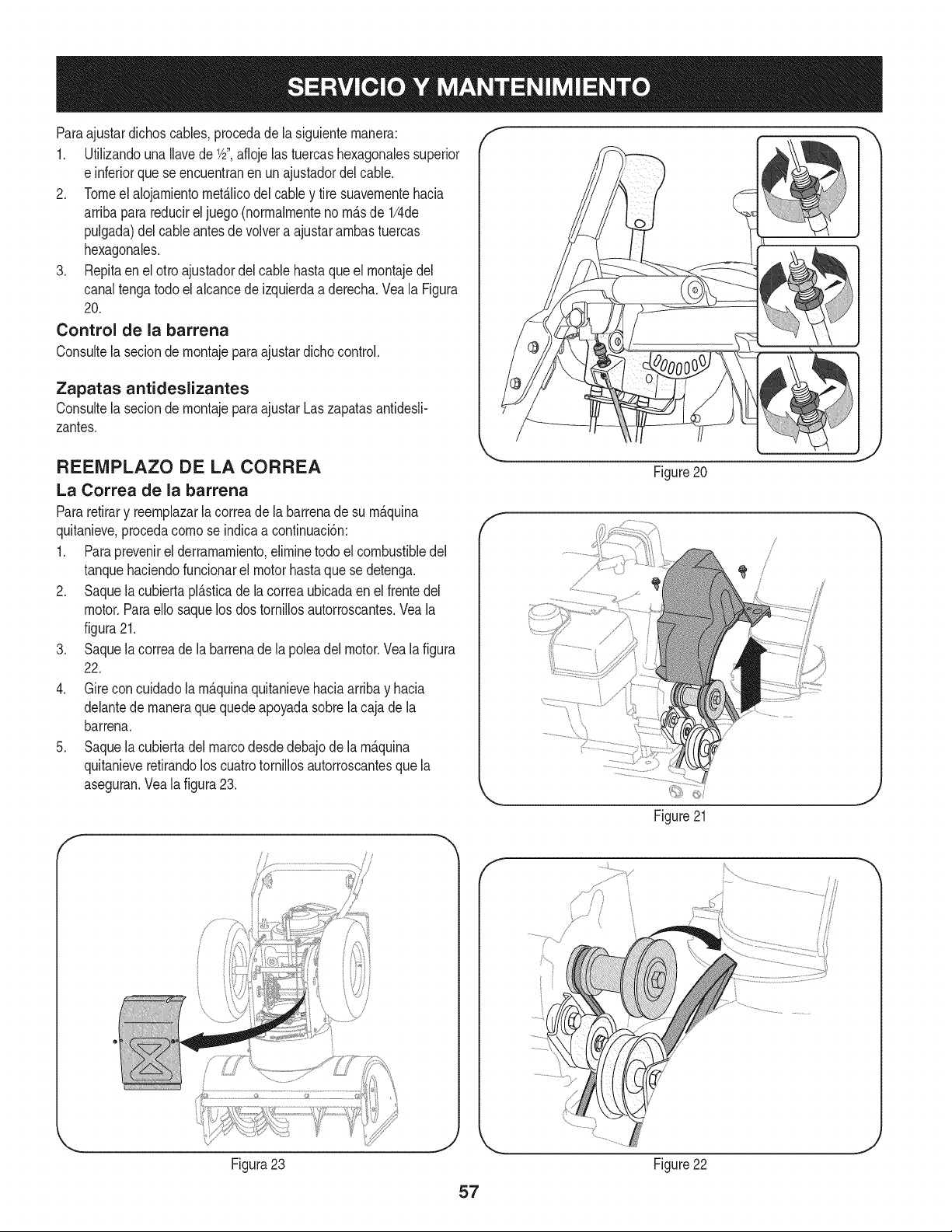
Paraajustardichoscables,procedade la siguienternanera:
1. UtiNzandouna Navede 1/d',aflojelas tuercashexagonalessuperior
e inferiorquese encuentranenun ajustadordelcable.
2. Tomeel alojarnientornet_Jicodel cabley tire suavernentehacia
arribaparareducireljuego (norrnalrnenteno rn_.sde 1/4de
pulgada)del cableantesde volvera ajustararnbastuercas
hexagonales.
3. Repitaen el otto ajustadordel cable hastaqueel rnontajedel
canaltengatodoel alcancedeizquierdaa derecha.Vea la Figura
20.
Control de la barrena
Consultela seciondernontajepara ajustardichocontrol.
Zapatas antideslizantes
Consultela seciondernontajepara ajustarLaszapatasantidesN-
zantes.
f
REENIPLAZO DE LA CORREA
La Correa de la barrena
Pararetirary reernplazarla correade la barrenade su rn_.quina
quitanieve,procedacornose indicaacontinuaci6n:
1. Paraprevenirel derramarniento,elirninetodo el combustibledel
tanquehaciendofuncionarel motorhastaquese detenga.
2. Saquela cubiertapl_.sticade la correaubicadaen el frentedel
motor.ParaeNosaquelos dos tornillosautorroscantes.Veala
figura21.
3. Saquela correade la barrenade la poleadel motor.Vealafigura
22.
4. Gire concuidadola rn_.quinaquitanievehaciaarribay hacia
delantede rnaneraque quedeapoyadasobrela cajade la
barrena.
5. Saquela cubiertadel marcodesdedebajode la rn_.quina
quitanieveretirandoloscuatrotorniNosautorroscantesquela
aseguran.Veala figura23.
f
Figura23
J
Figure20
/
Figure21
57
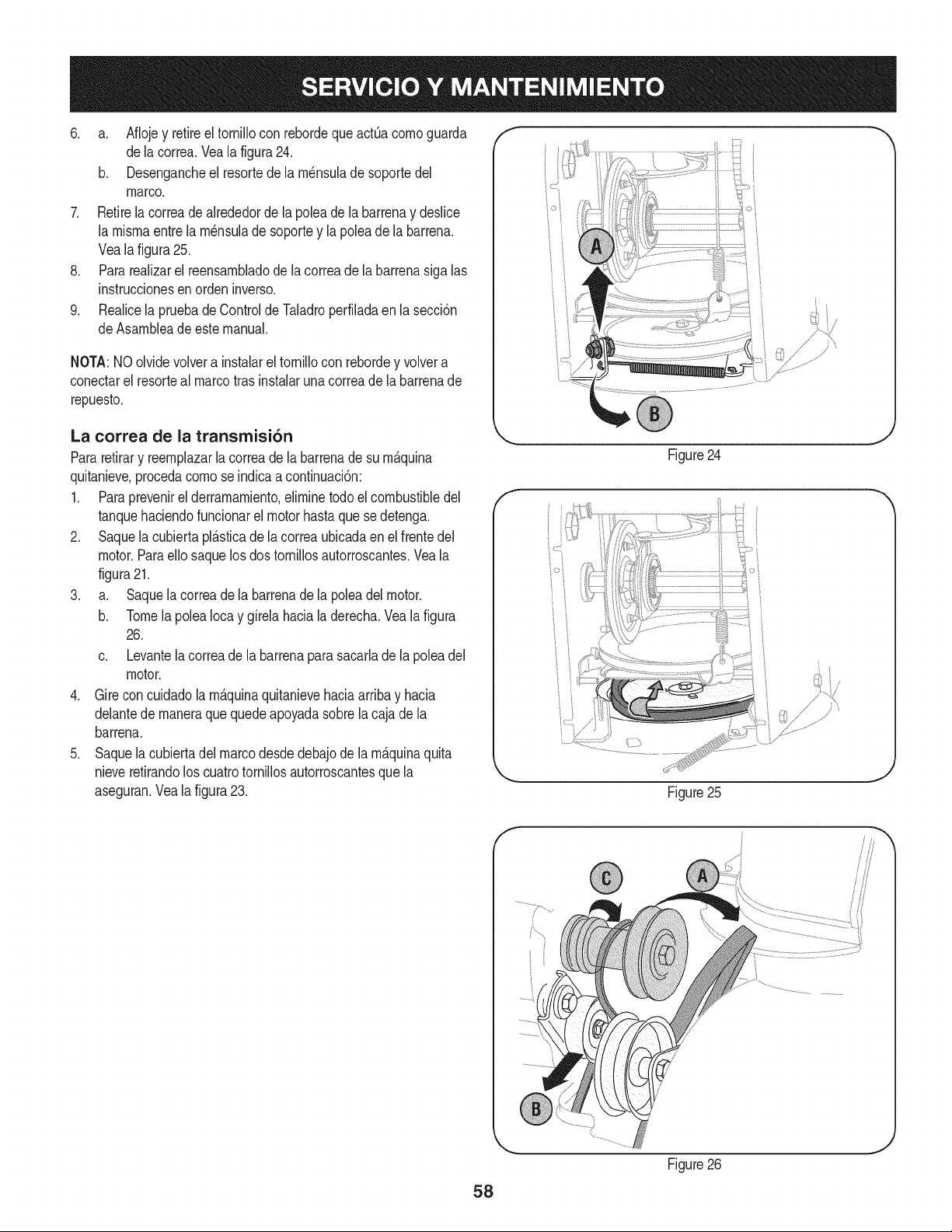
6. a. Aflojey retireel tornillocon rebordeque act0a comoguarda
dela correa.Veala figura24.
b. Desengancheel resortede la m_nsulade soportedel
marco.
7. Retirela correade alrededorde la poleade la barrenay deslice
la mismaentre la m_nsulade soportey lapoleadela barrena.
Veala figura25.
8. Pararealizarel reensambladode la correade la barrenasiga las
instruccionesen orden inverso.
9. Realicela pruebade Controlde Taladroperfiladaen lasecci6n
deAsambleade este manual.
NOTA:NOolvidevolvera instalarel tornillocon rebordey volvera
conectarel resorteal marcotrasinstalaruna correade la barrenade
repuesto.
La correa de la transmisi6n
Pararetirary reemplazarla correadela barrenade su m&quina
quitanieve,procedacomo se indicaacontinuaci6n:
1. Paraprevenirel derramamiento,eliminetodoel combustibledel
tanquehaciendofuncionarel motorhastaque sedetenga.
2. Saquela cubiertapl_.sticade la correaubicadaen el frentedel
motor.Paraello saquelosdos tornillosautorroscantes.Veala
figura21.
3. a. Saquela correade la barrenade la poleadelmotor.
b. Tomela polea Iocay girela haciala derecha.Vealafigura
26.
c. Levantela correade la barrenaparasacarlade la polea del
motor.
4. Girecon cuidadola m&quinaquitanievehaciaarribay hacia
delantede maneraque quedeapoyadasobrela cajade la
barrena.
5. Saquela cubiertadel marcodesdedebajode la m_.quinaquita
nieveretirandoloscuatrotornillosautorroscantesquela
aseguran.Veala figura23.
Figure24
/" }
_. i j
Figure25
Figure26
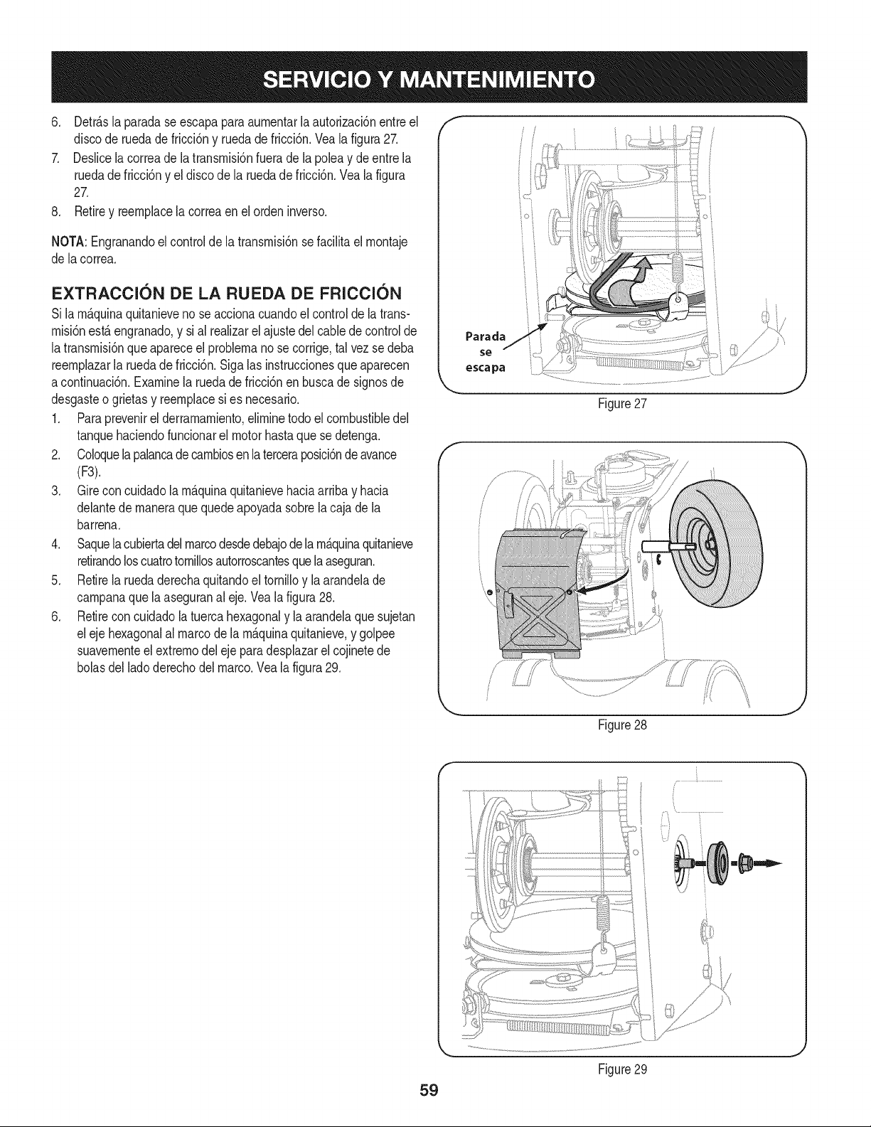
6, Detr_.slaparadaseescapaparaaumentarlaautorizacbnentreel
discoderuedadefricci6nyruedadefricci6n,Vealafigura27,
7, DeslicelacorreadelatransmM6nfueradelapoleaydeentrela
ruedadefriccbnyeldiscodelaruedadefriccbn,Vealafigura
27,
8, Retireyreemphcelacorreaenelordeninverso,
NOTA:Engranandoelcontroldelatransmisi6nsefacilitaelmontaje
delacorrea,
EXTRACCION DE LA RUEDA DE FRICCION
Si lamAquinaquitanieveno se accionacuandoel controlde la trans-
misi6nestAengranado,y sial realizarel ajustedel cabledecontrolde
latransmisi6nqueapareceel proNemano se corrige,tal vez se deba
reemplazarla ruedadefricci6n,Sigalas instruccionesqueaparecen
acontinuaci6n,Examinela ruedade fricci6nenbuscade signosde
desgasteo grietas y reemplacesi es necesario,
1, Paraprevenirel derramamiento,eliminetodo elcombustibledel
tanquehaciendofuncionarel motorhastaquese detenga.
2, Coloquelapalancadecambiosen la terceraposici6nde avance
(F3).
3. Gire concuidadola m_.quinaquitanievehaciaarribay hacia
delantede maneraque quedeapoyadasobrela cajade la
barrena.
4. Saquela cubiertadel marcodesdedebajodelam_.quinaquitanieve
retirandoloscuatrotornillosautorroscantesque laaseguran.
5. Retirela ruedaderechaquitandoel tornilloy la arandelade
campanaquela aseguranal eje. Veala figura28.
6. Retirecon cuidadola tuercahexagonaly la arandelaque sujetan
eleje hexagonalal marcode la m_.quinaquitanieve,y golpee
suavementeelextremodel eje para desplazarel cojinetede
bolasdel ladoderechodel marco.Vea la figura29.
Parada
se
escapa
f
ioi
i° i
Figure27
Figure28
J
59
Figure29
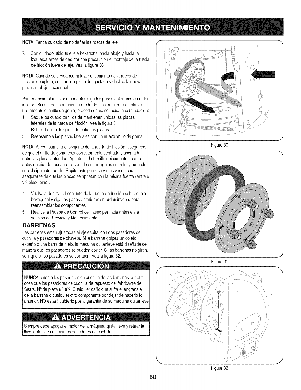
NOTA:TengacuidadodenodaSarlasroscasdeleje.
7. Concuidado,ubiqueelejehexagonalhaciaabajoyhaciala
izquierdaantesdedeslizarconprecauci6nelrnontajedelarueda
defricci6nfueradeleje.Vealafigura30.
NOTA:Cuandosedeseareernplazarelconjuntodelaruedade
fricci6ncornpleto,descartelapiezadesgastadaydeslicelanueva
piezaenelejehexagonal.
Parareensarnblarloscornponentessigalospasosanterioresenorden
inverso.Siest,.desrnontandolaruedadefricci6nparareernplazar
Onicarnenteelanillodegorna,procedacornoseindicaacontinuaci6n:
1. Saqueloscuatrotornillosdernantienenunidaslasplacas
lateralesdelaruedadefricci6n.Vealafigura31.
2. Retireelanillodegornadeentrelasplacas.
3. Reensarnblelasplacaslateralesconunnuevoanillodegorna.
NOTA:AIreensarnblarelconjuntodelaruedadefricci6n,asegOrese
dequeelanillodegornaestacorrectarnentecentradoyasentado
entrelasplacaslaterales.AprietecadatornilloQnicarnenteungiro
antesdegirarlaruedaenelsentidodelasagujasdelrelojyproceder
conelsiguientetornillo.Repitaesteprocesovariasvecespara
asegurarsedequelasplacasseaprietanconlarnisrnafuerza(entre6
y9pies-libras).
4. Vuelvaadeslizarelconjuntodelaruedadefricci6nsobreeleje
hexagonalysigalospasosanterioresenordeninversopara
reensarnblarloscornponentes.
5. RealicelaPruebadeControldePaseoperfiladaantesenla
secci6ndeServicioyMantenirniento.
BARRENAS
Las barrenasest_.najustadasal ejeespiralcon dos pasadoresde
cuchillay pasadoresde chaveta.Si la barrenagolpeaunobjeto
extraSoo unabarrade hielo,larn_.quinaquitanieveest,. diseSadade
rnaneraquelos pasadoresse puedencortar.Si las barrenasnogiran,
verifiquesi los pasadoresse cortaron.Vea la figura32.
NUNCAcarnbielos pasadoresde cuchillade las barrenaspor otra
cosaque los pasadoresde cuchillade repuestodelfabricantede
Sears,NOde pieza88389.Cualquierda_oquesufrael engranaje
dela barrenao cualquierotro cornponentepordejarde hacerloIo
anterior,NO estar_,cubiertopor la garanfiade su rn_.quinaquitanieve.
Siernpredebeapagarel motorde la rn_.quinaquitanievey retirarla
Ilaveantesde carnbiarlos pasadoresdecuchilla.
Figure30
J
Figure31
,f _,,
jJ ...........................
i i
Figure32
s'/
i}
}
/]/
.J
60
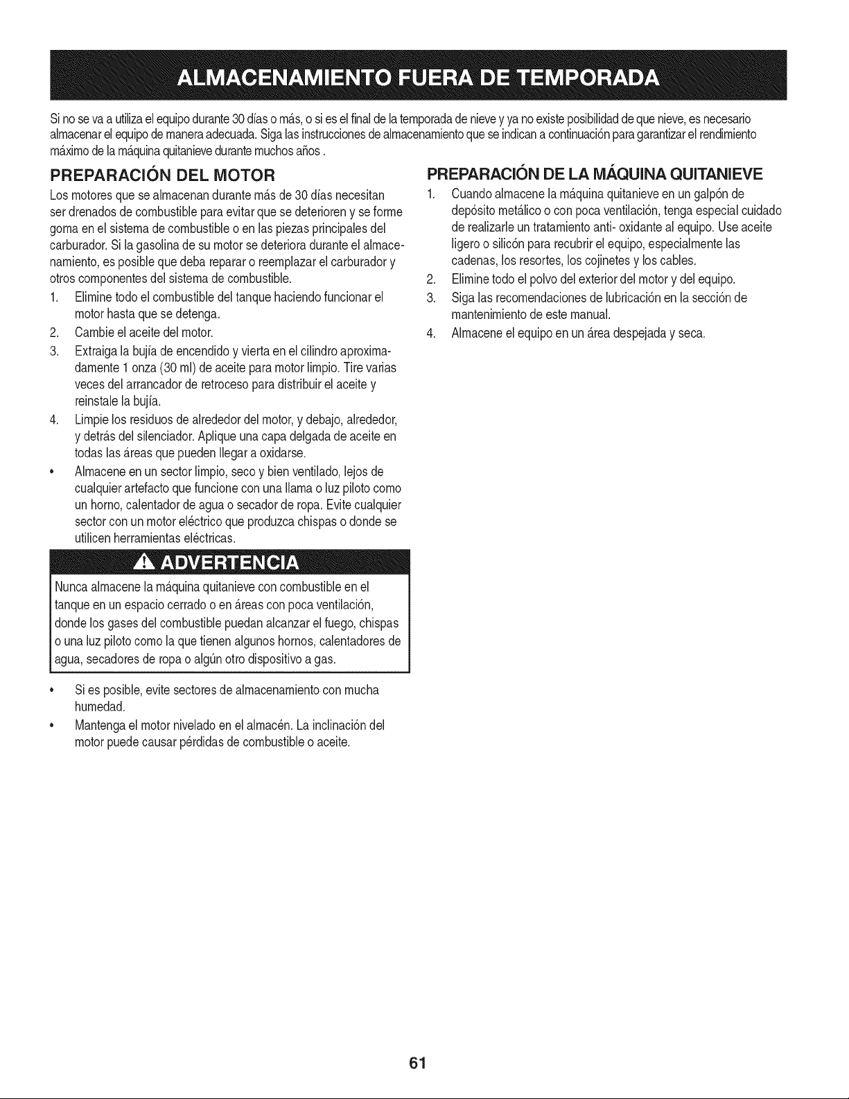
Sinosevaa utilizael equipodurante30 dfaso rn_.s,o sies el finalde la ternporadadenievey ya noexisteposibilidaddeque nieve,es necesario
alrnacenarel equipode rnaneraadecuada.Sigalasinstruccionesde alrnacenarnientoquese indicanacontinuaci6nparagarantizarelrendirniento
rn_.xirnodelarn_.quinaquitanieveduranternuchosa_os.
PREPARACI6N DEL MOTOR
Losrnotoresquese alrnacenandurantern&sde 30 dfas necesitan
serdrenadosde combustiblepara evitarque se deterioreny se forrne
gornaenel sisternade combustibleoen las piezasprincipalesdel
carburador.Si lagasoNnade su motorse deterioraduranteel alrnace-
narniento,es posiblequedeba repararo reernplazarelcarburadory
otroscornponentesdel sisternade combustible.
1. Elirninetodoel combustibledel tanquehaciendofuncionarel
motorhastaquese detenga.
2. Carnbieel aceitedel motor.
3. Extraigala bujfade encendidoy viertaen elcilindroaproxirna-
darnente1 onza(30 rnl)de aceitepara motorNrnpio.Tire varias
vecesdel arrancadorde retrocesoparadistribuirelaceitey
reinstalela bujfa.
4. Lirnpielos residuosde alrededordel motor,y debajo,alrededor,
y detr_.sdel silenciador.ApNqueunacapa delgadade aceiteen
todaslas _.reasque puedenNegara oxidarse.
• Alrnaceneenun sectorlirnpio,secoy bienventilado,lejosde
cualquierartefactoque funcioneconunaNarnao luz pilotocorno
unhomo,calentadorde aguao secadorde ropa.Evitecualquier
sectorcon un motorel_ctricoqueproduzcachispaso dondese
utilicenherrarnientasel_ctricas.
Nuncaalrnacenela rn_.quinaquitanieveconcombustibleenel
tanqueenun espaciocerradoo en _.reascon pocaventilaci6n,
dondelosgases del combustiblepuedanalcanzarel fuego,chispas
o unaluz pilotocornola que tienenalgunoshornos,calentadoresde
agua,secadoresde ropa o algQnotto dispositivoa gas.
PREPARACION DE LA iVlAQUINA QUITANIEVE
1. Cuandoalrnacenela rn&quinaquitanieveen un galp6nde
dep6sitornet_.licoo con pocaventilaci6n,tengaespecialcuidado
de realizarleuntratarnientoanti- oxidanteal equipo.Useaceite
ligeroo silic6npararecubrirel equipo,especialrnentelas
cadenas,los resortes,loscojinetesy loscables.
2. Elirninetodo el polvodelexteriordelmotory delequipo.
3. Siga las recornendacionesde lubricaci6nen la secci6nde
mantenirnientodeestemanual.
4. Alrnaceneel equipoen un_.readespejaday seca.
• Si es posible,evitesectoresdealrnacenarnientocon rnucha
hurnedad.
• Mantengael motorniveladoen el alrnac_n.Lainclinaci6ndel
motorpuedecausarperdidasde combustibleo aceite.
61
Elmotornoarranca
Elmotorfuncionade manera
err_.tica
Elmotorrecalienta
Demasiadavibraci6n
1. La palancade obturaci6nno est,. en la
posici6nON(encendido)
2. Se ha desconectadoel cablede la bujia
3. La bujia nofunciona correctamente
4. El tanquede combustibleest,. vado o el
combustiblees viejo
5. El motor no est,. cebado
6. La Ilavede seguridadno se encuentraen el
encendidodel motor
1. La unidadestS.funcionandoen la posici6n
CHOKE(obturaci6n)
2. EIcombustibleesviejo
3. Aguao suciedaden el sistemadel combus-
tible
4. Es necesarioajustarelcarburador
1. El carburadorno est,. ajustadocorrecta-
mente
1. Hay piezasque est_.nflojas o la barrena
est,.dafiada
1. Pongael interruptoren la posici6nCHOKE(obtura-
ci6n).
2. Conecteel cable a labujfa.
3. Limpie.ajuste la distanciadisruptivao cambie.
4. LJeneel tanquecon gasolinalimpiay fresca.
5. Cebeel motortal y como se indicaenla secci6nde
operaci6n.
6. Insertela Ilavetotalmentedentrodel interruptor.
1. Cambiela palancade obturaci6na la posici6nOFF
(apagado).
2. Lleneel tanquecon gasolinalimpiay fresca.
3. Vacieel tanquedel combustible.Vuelvaa Ilenarlo
concombustiblelimpio.
4. Contactecon su centrode partesy reparaciones
Sears.
1. Contactecon uncentrode partesy servicioSears.
.
Detengael motorde inmediatoy desconecteel
cablede labujia.Ajustetodoslos pernosy las
tuercas.Sila vibraci6ncontinQa.Ilevela unidada
reparara un centrode partesy reparaci6nSears.
tNECESITA MAS AYUDA?
_}Mc<:_r_V:l'_l'_I_ I_!_;pu_;V:_ y mS_; _!r_managemy.com - isin cargo!
En linea podr4 encontrar este rnar,ual y los rT/anualesde todos los otros productos que posea.
,, Sus preguntas se_'4r/respondidas pot nuestro equipo de espedalistas.
Obtenga un plan de mantenimiento personalizado para su hogar.
,, Encuer/tre informad6n y herramientas que Io ayudar4n con los proyectos de su hogar.
manage_hom?
62
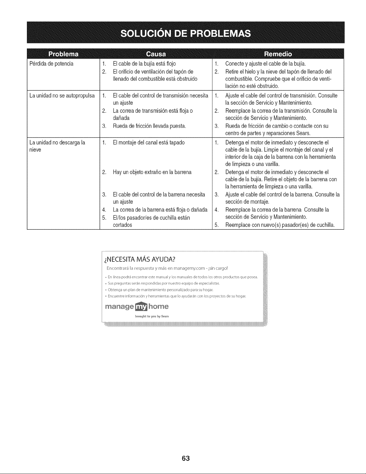
Perdidadepotencia 1. El cablede la bujfaest&flojo
2. El orificiode ventilaci6ndel tap6nde
Ilenadodel combustibleest,. obstruido
1. El cabledel controlde transrnisi6nnecesita
unajuste
2. La correade transrnisi6nest,.flojao
daSada
3. Ruedade fricci6nIlevadapuesta.
1. El rnontajedel canalest,. tapado
La unidadnose autopropulsa
La unidadnodescargala
nieve
2. Hay un objetoextraSoen la barrena
3. El cabledel controlde la barrenanecesita
unajuste
4. La correade la barrenaest,. flojao daSada
5. El/los pasador/esde cuchillaest_.n
cortados
1. Conectey ajusteel cablede la bujfa.
2. Retireel hieloy la nievedel tap6nde Ilenadodel
combustible.Cornpruebeque el orificiode venti-
laci6nnoest_ obstruido.
1. Ajusteel cabledel controlde transrnisi6n.Consulte
lasecci6ndeServicioy Mantenirniento.
2. Reernplacela correade la transrnisi6n.Consultela
secci6nde Servicioy Mantenirniento.
3. Ruedade fricci6nde carnbioo contactecon su
centrode partesy reparacionesSears.
1. Detengael motorde inrnediatoy desconecteel
cabledela bujia. Lirnpieel rnontajedel canaly el
interiorde lacaja dela barrenacon laherrarnienta
delirnpiezao una varilla.
2. Detengael motorde inrnediatoy desconecteel
cabledela bujia. Retireel objetode la barrenacon
laherrarnientade lirnpiezao unavarilla.
3. Ajusteel cabledel controlde la barrena.Consultela
secci6nde rnontaje.
4. Reernplacela correade la barrena Consultela
secci6nde Servicioy Mantenirniento.
5. Reernplacecon nuevo(s)pasador(es)decuchilla.
63
MTD CONSUMER GROUP, iNC. (MTD), el Bordo de Recursos de Aire de California (CARB)
y la Agencia de Protecci6n Medioambiental de Estados Unidos (U. S. EPA)
Declaraci6n de Garantia del Sistema de Control de Emisiones
(Derechos y obligaciones del propietario seg_n la garantia contra defectos)
LACOBERTURADESISTEMADECONTROLDEEMISIONES APLICABLEA MOTORESCERTIFICADOSCOMPRADOSENCALIFORNIA
EN2005Y A PARTIRDE ENTONCES,QUESON USADOSEN CALIFORNIA,Y HASTAANO2005DE MODELOCERTIFICADOY MOTORES
POSTERIORESQUESON COMPRADOSY USADOSENOTRAPARTEEN LOSESTADOSUNIDOS.
Californiayen otra parteen la Coberturade Garantiade DefectosdeControlde Emisi6nde los EstadosUnidos
El Bordode Recursosde Airede California(CARB),la U.S. EPAy MTDsecomplacenen explicarla garantiadel sistemade controlde emisiones
de su motorparaequipotodo terreno,modelo,aSo2005 y versionesposteriores.EnCalifornia,los nuevosmotorespequeSospara equipotodo
terrenose debendise5ar,fabricary equiparparacumplir conest_.ndaresde antinieblat6xicade estados.En otraparteen los EstadosUnidos,
el nuevonocamino,motoresde ignici6nde chispacertificadospara el modelo2005 y m_.starde,debe encontrarel juego de est_.ndaressimilar
adelantepor los EstadosUnidos.EPA.MTDdebegarantizarel sistemadecontrolde emisionesdesu motorpor el periodode tiempoindicadom&s
abajo,siemprey cuandono hayaexistidousoincorrecto,negligencianimantenimientoinadecuadode su motorpequeBoparaequipotodoterreno.
El sistemadecontrolde emisionespuedeincluirpiezascomo,porejemplo,el carburador,sistemadeinyecci6nde combustible,el sistemade
encendido,el catalizador,losdep6sitosde combustible,abastecedecombustiblelineas,gorrasde combustible,v&lvulas,latas,filtros,mangueras
devapor,abrazaderas,conectoresy otroscomponentesrelacionadoscon lasemisiones.
Dondeexistauna condici6ncubiertapor la garantia,MTDreparar&su motorpequeBoparaequipotodoterrenosincostoalgunoincluyendoel
diagn6stico,laspiezasy la manode obra.
COBERTURA DE LA GARANTJA DEL FABRICANTE:
Estesistemade controldeemisionesse garantizaporel t@rminode dos a5os.Si algunapiezade su motorrelacionadacon lasemisioneses
defectuosa,MTD reparar&o sustituir&dichapieza.
RESPONSABJLIDADES DEL PROPIETARIO SEGUN LA GARANTJA:
Comopropietariode un motorpequeSode equipotodoterreno,ustedes responsablede realizarel mantenimientonecesarioquefigura en el
manualdel propietario.MTDle recomiendaqueconservetodos los recibosquecubrenlos serviciosde mantenimientodel motorpeque5opara
equipotodoterreno,noobstanteIo cual MTDno podr&denegarel cumplimientode la garantiaQnicamenteporlafalta de reciboso por su imposibi-
lidadde asegurarque se realizar_.ntodoslos serviciosde mantenimientoprogramado.
Comopropietariodel motorpeque5oparaequipotodo terreno,sinembargo,ustedtambi@ndebesaberque MTDpuededenegarlacoberturadela
garantiasi su motorpeque5oparaequipotodoterrenoo unapiezadel mismofallandebidoa usoincorrecto,negligencia,mantenimientoindebido
o a modificacionesnoaprobadas.
Ustedes responsablede presentarla cortadorade cespedal centrode distribuci6no de mantenimientode MTDCONSUMERGROUP,INC.tan
prontocomo aparecierael problem& Lasreparacionescubiertaspor la garantiasedeben Ilevara cabo enun lapsorazonableque no excedade
30dias. Si desearealizaralgunaconsultacon respectoa la coberturade lagarantia,debeponerseencontactocon su distribuidorlocalde MTD.
Paracomunicarseconla LineadeAsistenciaal Clientede Distribuidoresde MTD,Ilameal nQmero(877)282-8684.
REQUERJMJENTOS DE GARANTJA SOBRE DEFECTOS PARA MOTORES PEQUENOS DE EQUJPO TODO TERRENO
DE 1995YVERSJONES POSTERJORES:
Estasecci6nse aplicaa motorespeque5osdeequipotodo terrenode 1995y versionesposteriores.El periodode garantiacomienzaa partirde la
fechaen queel motoro el equipo seentreganal compradorfinal.
(a) Coberturade la garantiacontraemisionesgenerales
MTDgarantizaal compradorfinaly acada compradorsubsiguienteque el motor:
(1)hasido diseSado,construidoy equipadode maneraque cumplacontodas las regulacionesvigentesadoptadasporel Departamentodelos
RecursosdeAire envirtuda suautoridadconferidaen los capitulos1 y 2, Parte5, Divisi6n26 del C6digode Saludy Seguridad;y
(2)est,. librede defectosen los materialesyen la manode obraquecausenlafalla deunapiezabajogarantiaque seaid@nticaen todos los
aspectosmaterialesa la piezacomo aparecedescriptaen la aplicaci6ndel fabricantedel motorparacertificaci6npor unperiodode dos a5os.
_arantia sobre piezasrelacJonadasconemisJonesse interpretar_,de la sJguientemanera:
(1)Cualquierpiezacubierta por garantiaque no est@programadapara su reemplazosegQnel mantenimientorequeridoenlas instrucciones
escritasdela Subsecci6n(c) debeestargarantizadapor unperiodode garantiadefinidoen la Subsecci6n(a)(2). Sila piezafalladurante
el periododecoberturade la garantia,la mismaser_.reparadao reemplazadapor MTD de acuerdocon la Subsecci6n(4)a continuaci6n.
Cualquierpiezareparadao reemplazadasegQnla garantiasegarantizarB,por el resto del periodode garantia.
(2) Cualquierpiezacubiertapor garantiaque est@programadasolopara inspecci6nregularen las instruccionesescritasde la Subsecci6n
(c) debe estargarantizadapor un periododegarantiadefinidoenla Subsecci6n(a) (2). Unadeclaraci6nen dichasinstruccionesporescrito
alefectode "reparaci6no reemplazosegQnseanecesario"no reducir_,elperiodode coberturade la garantia.Cualquierpiezareparadao
reernplazadasegQnlagarantiasegarantizar_,porelrestodelperiododegarantia.
(3) Cualquierpiezagarantizadaqueest_prograrnadaparareernplazosegQnelrnantenirnientorequeridodeconforrnidadconlasinstruc-
clonesescritasdelaSubsecci6n(c)segarantizaporelperiododetiernpoanterioralaprirnerafechadereernplazoprograrnadaparaesa
pieza.Silapiezafallaantesdelprimerreernplazoprogramatic,larnisrnaser_.reparadaoreernplazadaporMTDdeacuerdoconlaSubsecci6n
(4)acontinuaci6n.Cualquierpiezareparadaoreernplazadabajogaranfiasegarantizar_,porelrestodelperiodoanterioralprimerreernplazo
programaticpuntualparaesapieza.
(4)Lareparaci6noelreernplazodecualquierpiezagarantizadadeconforrnidadconlasdisposicionesdelagaranfiaqueaquiseestipulase
deberealizarenuncentrodegaranfiasincostoalgunoparaelpropietario.
(5)SinperjuiciodelasdisposicionesdelaSubsecci6n(4)anterior,losservicioso reparacionescubiertosporlagaranfiadebensersurnin-
istradosportodosloscentrosdedistribuci6ndeMTDquetenganlafranquiciapararealizarreparacionesyrnantenirnientoalosrnotoresen
cuesti6n.
(6)ElpropietarionodebeafrontarningQncargoparatrabajosdediagn6sticoqueIlevena laconclusi6ndequeunapiezabajogaranfiapresenta
efectivarnentedefectos,siernpreycuandodichodiagn6sticoseaIlevadoacaboenuncentrocubiertoporlagarantia.
(7)Elfabricantedelmotoresresponsableporda_oscausadosaotroscornponentesdernotoresderivadosdelafallabajogaranfiadecualquier
piezagarantizada.
(8)DurantetodoelperiododegaranfiadelmotordefinidoenlaSubsecci6n(a)(2),MTDrnantendr_,unsurninistrodepiezascubiertaspor
garantiasuficienteparasatisfacerladernandaesperadaparatalespiezas.
(9)Cualquierpiezadereernplazosepodr_,usarparaelcurnplirnientodelrnantenirnientooreparacionesbajogaranfia,ysesurninistrar_,sin
cargoalpropietario.Dichousonoreducir_,lasobligacionesdegarantiadeMTD.
(10)Nosepodr_.nusarpiezasadicionalesnirnodificadasquenoest_nexentasdeacuerdoconelDepartarnentodelosRecursosdelAire(Air
ResourcesBoard).Elusodepiezasadicionalesornodificadasnoexentasser_.causasuficienteparaanularunreclarnobajogaranfiarealizado
deacuerdoconestearticulo.Elfabricantedelmotornotendr_,responsabilidad,enconforrnidadconestearticulo,degarantizarfallasdepiezas
garantizadasquefuerencausadasporelusodeunapiezanoexentaadicionalornodificada.
.(c)MTDincluir_,unacopiade lasiguientelistade piezasbajogarantiacontra ernisionescon cadanuevomotor,utilizandolas partesde la lista
a_plicablesal motor.
(1)Sisternadernedici6nde combustible
• Sisternade rnejorapara inicioen frio (cebadosuave)
• Carburadory cornponentesinternos
• Bornbade combustible
• Dep6sitode combustible
(2) Sisternadeinducci6ndeaire
• Filtrode aire
• Colectorde entrada
(3) Sisternadeencendido
• Bujia(s)
• Sisternade encendidopor magneto
(4)Sisternadeescape
• Catalizador
• SAI (v_Jvulade Ca_a)
(5) Cornponentesvarios utilizadosen el sisternaanterior
• V_Jvulase interruptoresde vado, ternperatura,posici6nsensiblesal tiernpo
• Conectoresy rnontajes
(6)Controlde Evaporative
• Manguerade CombustiblecertificadaparaARB evaporativeernisi6nde 2006.
• Abrazaderasde Manguerade Combustible
• Gorrade combustibleatada
• Latade carb6n
• Lineasde vapor
GD0C-100174Rev.B
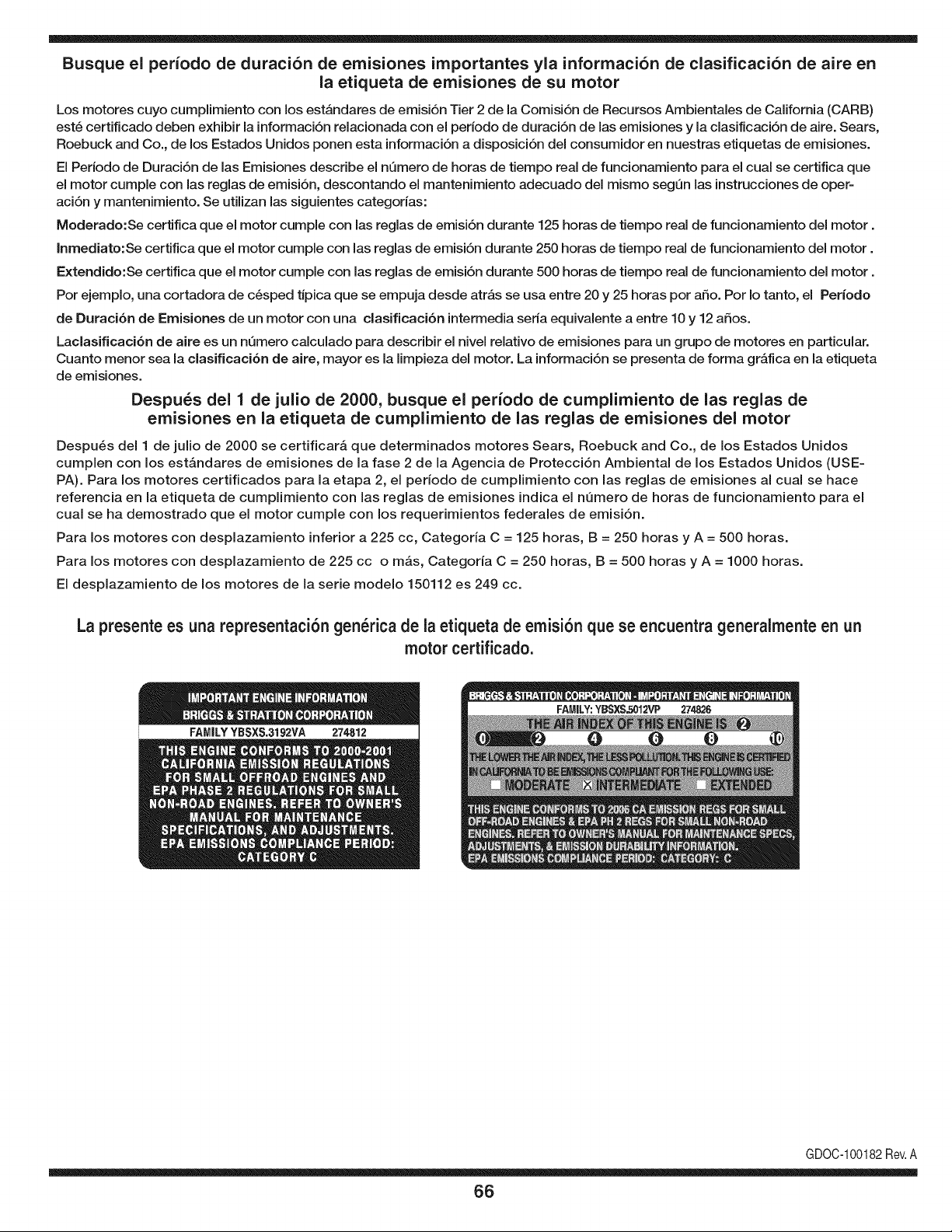
Busque el periodo de duraci6n de emisiones importantes yla informaci6n de clasificaci6n de aire en
la etiqueta de emisiones de su motor
Los motores cuyo cumpiimiento con los estAndares de emisi6n Tier 2 de la Comisi6n de Recursos Ambientales de California (CARB)
est6 certificado deben exhibir la informaci6n relacionada con el perJodo de duraci6n de las emisiones y la clasificaci6n de aire. Sears,
Roebuck and Co., de los Estados Unidos ponen esta informaci6n a disposici6n deJ consumidor en nuestras etiquetas de emisiones.
El Periodo de Duraci6n de las Emisiones describe el nQmero de horas de tiempo real de funcionamiento para el cual se certifica que
el motor cumple con las reglas de emisi6n, descontando el mantenimiento adecuado deJ mismo segQn las instrucciones de oper-
aci6n y mantenimiento. Se utilizan las siguientes categorias:
Moderado:Se certifica que el motor cumpie con las reglas de emisi6n durante 125 horas de tiempo real de funcionamiento deJ motor.
Inmediato:Se certifica que el motor cumple con las reglas de emisi6n durante 250 horas de tiempo real de funcionamiento deJ motor.
Extendido:Se certifica que el motor cumple con las reglas de emisi6n durante 500 horas de tiempo real de funcionamiento deJ motor.
Por ejemplo, una cortadora de c6sped tJpica que se empuja desde atrAs se usa entre 20 y 25 horas por afio. Por Io tanto, el Periodo
de Duraci6n de Emisiones de un motor con una clasificaci6n intermedia seria equivalente a entre 10 y 12 afios.
Laclasificaci6n de aJre es un nQmero calculado para describir eJnivel reiativo de emisiones para un grupo de motores en particular.
Cuanto menor sea Jaclasificaci6n de aire, mayor es JaJimpieza deJ motor. La informaci6n se presenta de forma gr&fica en Jaetiqueta
de emisiones.
Despu_s del 1 de julio de 2000, busque el periodo de cumplimiento de las reglas de
emisiones en la etiqueta de cumplimiento de las reglas de emisiones del motor
Despu_s deJ 1 de julio de 2000 se certificar_, que determinados motores Sears, Roebuck and Co., de los Estados Unidos
cumpien con los estAndares de emisiones de la fase 2 de la Agencia de Protecci6n Ambiental de los Estados Unidos (USE-
PA). Para los motores certificados para la etapa 2, el periodo de cumpiimiento con las reglas de emisiones al cual se hace
referencia en la etiqueta de cumpiimiento con las reglas de emisiones indica el nQmero de horas de funcionamiento para el
cuaJ se ha demostrado que el motor cumpie con los requerimientos federales de emisi6n.
Para los motores con desplazamiento inferior a 225 cc, Categoria C = 125 horas, B = 250 horas y A = 500 horas.
Para los motores con desplazamiento de 225 cc o mAs, Categoria C = 250 horas, B = 500 horas y A = 1000 horas.
El despiazamiento de los motores de la serie modelo 150112 es 249 cc.
La presente es una representaci6n gen_rica de la etiqueta de emisi6n que se encuentra generaimente en un
motor certificado.
FAMILYYBSXS.3192VA 274812
GDOC-100182Rev.A
66
Felicitacionespor haberrealizadounaadquisici6ninteligente.El
productoCraftsman@queha adquiridoest_dise_adoy fabricado
parabrindarrnuchosa_osde funcionarnientoconfiable.Perocorno
todoslos productosa vecespuederequerirde reparaciones.Esen
esernornentocuandoel disponerde un Acuerdode protecci6npara
reparacionesle puedeahorrardineroy problernas.
A continuaci6nsedetallanlos puntosincluidosenel Acuerdo:
• Servicio experto prestadopor nuestros10,000especialistasen
reparacionesprofesionales
• Servicio ilirnitadosin cargopara laspiezasy la rnanode obraen
todaslas reparacionescubiertas
• Reernplazodel productohasta 1500d61aressi no es posible
repararel productocubierto
• Descuentode 10%del precionormaldel servicioy de las piezas
relacionadascon el rnisrnoqueno est_ncubiertaspor el acuerdo;
adern&s,10%del precionormalde laverificaci6nde rnanten-
irnientopreventivo
• Ayudar_pida pot tel_fono- IoIlarnarnosResoluci6nR_pida- el
apoyotelef6nicode un Charnuscaal representante.Pienseen
nosotroscornoel manual"de undue_ohablador."
Unavezadquiridoel Acuerdo,puedeprograrnarel serviciocon
tan s61orealizaruna Ilarnadatelef6nica.PuedeIlarnarencualquier
mornentodeldia o dela nocheo prograrnarun servicioen linea.
ElAcuerdode Protecci6nde Reparaci6nes una cornprasin riesgo.
Siustedanulapor alguna raz6nduranteel periodode garantiade
producto,proporcionarernosun reernbolsoIleno.O,un reernbolso
prorrateadoencualquiermornentodespu_sdelperiodode garantia
de productoexpira,iAdquieraboysu acuerdode protecci6npara
reparaciones!
Seaplican deterrninadaslirnitaciones y exclusiones.Paraobtener
inforrnaci6nadicional y preciosen los Estados UnidosIlarne al
1-800-827-6655.
El*Coverage en Canad_variaen algunosarticulos. Paradetalles
Ilenosla IlarnadaCharnuscaCanad_en 1-800-361-6665.
Servicio de instalaci6nde Sears
Sideseasolicitarla instalaci6nprofesionalde Searsde aparatos
dorn_sticos,dispositivosparaabrirportones,calentadoresde agua
y otrosarficulosdorn_sticosirnportantes,en los EstadosUnidoso
Canad_Ilarneal 1-800-4-MY-HOME®.
67

Your Home
For expert troubleshooting and home solutions advice:
www.managemyhome.com
For repair - in your home - of all major brand appliances,
lawn and garden equipment, or heating and cooling systems,
no matter who made it, no matter who sold it!
For the replacement parts, accessories and
owner's manuals that you need to do-it-yourself.
For Sears professional installation of home appliances
and items like garage door openers and water heaters.
1-800-4-MY-HOME ® (1-800-469-4663)
Call anytime, day or night (U.S.A. and Canada)
www.sears.com www.sears.ca
Our Home
For repair of carry-in items like vacuums, lawn equipment,
and electronics, call anytime for the location of your nearest
Sears Parts & Repair Service Center
1-800-488-1222 (U.S.A.) 1-800-469-4663 (Canada)
www.sears.com www.sears.ca
To purchase a protection agreement on a product serviced by Sears:
1-800-827-6655 (U.S.A.) 1-800-361-6665 (Canada)
Para pedir servicio de reparaci6n
a domicilio, y para ordenar piezas:
1-888-SU-HOGAR ®
(1-888-784-6427)
Au Canada pour service en fran£ais:
1-800-LE-FOYER M°
(1-800-533-6937)
www.sears.ca
® Registered Trademark / TMTrademark / SM Service Mark of Sears Brands, LLC
SM
® Marca Registrada / TMMarca de F&brica / Marca de Servicio de Sears Brands, LLC
MCMarque de commerce / MD Marque depos6e de Sears Brands, LLC © Sears Brands, LLC