
SEARS
I:
aFTSHaN°
MODEL NU;_BER 917.259566 OWNER'S MANUAL
• Assembly
• Operation
• Customer Responsibilities
• Service and Adjustments
• Repair Parts
For answers to your questions
about this product, Call:.
1-800-659-5917
SearsCraftsman Help Line
5 am- 5pm, Mon- Sat
CAUTION: Read and follow all safety rules and instructions before operating this equipment.
FOR CONSUMER ASSISTANCE HOT LINE, CALL THIS TOLL FREE NUMBER: 1-800-659-5917
SAFETY RULES
A
Safe Operation Practices for Ride-On Mowers u
IMPORTANT: THIS CUTTING MACHINE IS CAPABLE OF AMPUTATING HANDS AND FEET AND THROWING OBJECTS.
FAILURE TO OBSERVE THE FOLLOWING SAFETY INSTRUCTIONS COULD RESULT iN SERIOUS INJURY OR DEATH.
I. GENERAL OPERATION
• Read,undemtand,and followell instructionsinthe manual
and onthe machinebeforestarting.
• Only allow responsibleadults, who ere familiar with the
instructions,to operatethemachine.
• Clear the area of obects such as rocks,toys,wire, etc.,
whc_ cou d bepickedup andthrownbytheblade.
• Besuretheareaisclearofotherpeoplebeforemowing.Stop
machineifanyoneentersthearea.
• Nevel"carrypassengers.
• Do notmowinreverseunlessabsolutelynecessary.Always
lookdownand behind beforeand whilebacking.
• Beawareofthemowerdischargedirectionanddo notpoint
it at anyone. Do notoperatethe mowerwithouteitherthe
entiregrasscatcherortheguardin place.
• Slowdownbefore turning.
• Never leavea runningmachineunattended.Alwaystumoff
blades, set parkingbrake,stop engine,and remove keys
beforedismounting.
• Turnoffbladeswhen notmowing.
• Stop engine beforeremoving grasscatcheror unclogging
chute.
• Mow onlyindaylightor goodartificiallight.
• Do not operatethe machinewhile underthe influenceof
alcoholordrugs.
• Watchfortrafficwhenoperatingnearorcrossingroedways.
• Use extracare when loadingor unloadingthemachineinto
e traileror truck.
II. SLOPE OPERATION
Slopes are a major factor related to loss-of-control and
tipover accidents, which can result in severe injury or
death. All slopes require extra caution. Ifyou cannot back
up the slope or if you feel uneasy on it, do not mow it.
DO:
• Mow up and downslopes,notacross.
• Removeobstaclessuchas recks,tree limbs,etc.
• Watch for holes, ruts, or bumps. Uneven terrain could
overfumthe machine. Tallgrasscan hideobstacles.
• Useslowspeed. Choosea lowgearsothatyouwillnothave
tostopor shiftwhileon theslope.
• Follow the manufacturer's recommendationsfor wheel
weightsorcounterweightstoimprovestability.
• Use extra care with grass catchersor otherattachments.
These canchangethestabilityofthemachine.
• Keepallmovementontheslopesslowandgradual. Do not
make suddenchangesin speed ordirection.
• Avoidstartingor stoppingon a slope. Iftireslosetraction,
disengagethe bladesandproceedslowlystraightdownthe
slope.
DO NOT:
• Donottumonslopesunlessnecessary,andthen,tumslowly
and graduallydownhill,ifpossible.
• Do notmow near drop-offs,ditches,or embankments.The
mowercouldsuddenlyturnoverifa wheel isovertheedge
of a cliffor ditch,or if an edgecaves in.
• Do not mowon wet grass. Reducedtractioncouldcause
sliding.
• Donottrytostabilizethemachinebyputtingyourfootonthe
ground.
• Do notusegrasscatcher onsteepslopes.
III. CHILDREN
Tragic accidents can occur ifthe operator isnot alertto the
presence of children. Children are often attracted to the
machine and the mowing activity. Never assume that
children will remain where you last saw them.
• Keepchildrenoutofthemowingareaandunderthewatchful
careofanotherresponsibleadult.
Bealertand turnmachineoftifchildrenenterthearea.
• Beforeandwhen backing,lookbehindand downfor small
children.
• Never carry children. They may fall offand be seriously
injuredor interferewithsafe machineoperation.
• Neverallowchildrento operatethe machine.
• Use extra care when approachingblindcomers,shrubs,
trees,orotherobjectsthatmay obscurevision.
IV. SERVICE
• Useextracareinhandlinggasolineandotherfuels.Theyare
flammableandvaporsareexplosive.
Useonlyanapprovedcontainer.
Never remove gas cap or add fuel with the engine
running. Allowenginetocoolbeforerefueling.Do not
smoke,
Neverrefuelthemachineindoors.
Neverstorethe machineor fuelcontainerinsidewhere
there isan openflame, suchas.a waterheater.
• Never run a machineinsidea closedarea.
• Keepnutsand belts,especiallybladeattachmentboltstight
andkeepequipmentin goodcondition.
• Never tamper with safety devices. Check their proper
operationragulady.
• Keepmachinefreeofgrass,leaves,orotherdebrisbuild-up.
Clean oil or fuel spillage. Allow machineto coolbefore
storing.
• Stop and inspectthe equipmentif you strike an object.
Repair,ifnecessary,before restarting.
• Nevermakeadjustmentsor repairswiththeenginerunning.
• Grasscatchercompenantserasubjecttowear,damage,and
deterioration,which could expose movingparts or allow
objectsto be thrown, Frequentlycheckcomponentsand
replacewithmanufacturer'srecommendedparts,when nec-
essary.
• Mowerbladesare sharpandcancut. Wraptheblade(s)or
weargloves,anduseextracautionwhen servicingthem.
• Check brake operationfrequently. Adjustand serviceas
required.
Look for this symbol to point out important
safety precautions. It means
CAUTION!II BECOME ALERTIn YOUR
SAFETY IS INVOLVED.
CAUTION: Always disconnect spark plug
wire endplace wire where Itcannotcontact
spark plug In order to prevent accidental
starting when setting up, transporting,
adjusting or making repairs.
A WARNING A
The engine exhaust from this product contains
chemicals known to the State of California to
cause cancer, birth defects, or other reproduc-
tive harm.
2
CONGRATULATIONS on your purchase of a Sears
Tractor. It has been designed, engineeredand manufac-
tured to give you the best possible dependability and
performance.
Should you experience any problem you cannot easily
remedy, please contact your nearest Sears Authorized
Service Center/Department. We have competent, well-
trainedtechniciansandthepropertoolstoserviceor repair
this tractor.
Please read and retainthis manual. The instructionswill
enableyoutoassembleand maintainyourtractorproperly.
Alwaysobservethe "SAFETY RULES".
MODEL
NUMBER 917.259566
SERIAL
NUMBER
DATEOFPURCHASE
THEMODELANOSERIALNUMBERSWILLBEFOUND
ON A PLATE UNDER THE SEAT.
YOU SHOULD RECORD BOTH SERIAL NUMBER AND
! DATE OF PURCHASE AND KEEP IN A SAFE PLACE
I FOR FUTURE REFERENCE.
MAINTENANCE AGREEMENT
A Sears Maintenance Agreement is available on this prod-
uct. Contact your nearest Sears store for details.
CUSTOMER RESPONSIBILITIES
Read and observe the safety rules.
Follow a regular schedule inmaintaining, caring forand
using your tractor.
• Follow the instructions under "Customer Responsibili-
ties" and =Storage" sections of this owner's manual.
WARNING: This tractor is equipped with an internal
combustion engine and should not be used on or near any
unimproved forest-covered, brush-covered or grass-cov-
ered land unless the engine's exhaust system isequipped
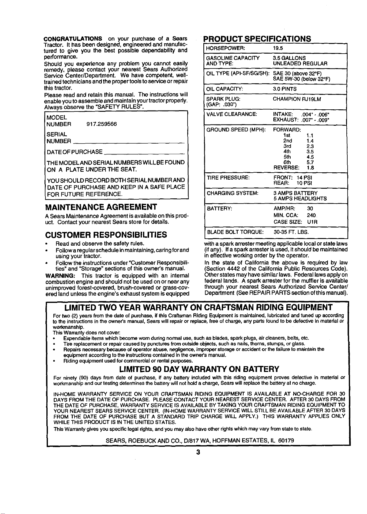
PRODUCT SPECIFICATIONS
HORSEPOWER: 19.5
GASOLINE CAPACITY 3.5 GALLONS
ANDTYPE: UNLEADED REGULAR
OIL TYPE (API-SF/SG/SH): SAE 30 (above32°1=)
SAE 5Wo30 (below 32°F)
OIL CAPACITY: 3.0 PINTS
I
SPARK PLUG: CHAMPION RJ19LM
GAP: .030")
VALVE CLEARANCE: INTAKE: .004" ÷.006"
EXHAUST: .007" - .009"
GROUND SPEED (MPH): FORWARD:
1st 1.1
2nd 1.4
3rd 2.3
4th 3.5
5th 4.5
6th 5.7
REVERSE: 1.8
TIRE PRESSURE: FRONT: 14 PSI
REAR: 10 PSI
CHARGING SYSTEM: 3 AMPS BATTERY
5 AMPS HEADLIGHTS
BATTERY: AMPiHR: 30
MIN. CCA: 240
CASE SIZE: UtR
BLADE BOLT TORQUE: 30-35 FT. LBS.
witha sparkarrastermeeting applicablelocalorstate laws
(ifany). Ifa sparkarrester isused,itshouldbe maintained
in effectiveworkingorder bythe operator.
In the state of Californiathe above is required by law
(Section4442 of the California Public ResourcesCode).
Other statesmay havesimilarlaws. Federal lawsapplyon
federal lands. A sparkattester for the muffler isavailable
through your nearest Sears Authorized Service Center/
Department (See REPAIR PARTSsectionofthismanual).
LIMITED TWO YEAR WARRANTY ON CRAFTSMAN RIDING EQUIPMENT
For two (2) years fromthe date ofpurchase,if thisCraftsmanRiding Equipmentis maintained,lubricatedand tuned up according
tothe instructionsin the owner's manual, Seam willrepairor replace, free ofcharge, anypartsfound to be defectivein material or
workmanship.
ThisWarrantydoes not cover:
Expendable itemswhichbecome worn duringnormaluse,suchas blades,spark plugs,air cleaners,belts,etc.
Tire replacementor repaircaused by puncturesfromoutsideobjects,suchas nails,thorns,stumps,orglass.
Repairs necessarybecause ofoperatorabuse, negligence,improperstorage oraccident orthe failureto maintain the
equipmentaccordingto the instructionscontainedinthe owner'smanual.
Ridingequipment usedforcommercialor rentalpurposes.
LIMITED 90 DAY WARRANTY ON BATTERY
For ninety (90) days from date of purchase, if any battery includedwith this riding equipment proves defective in material or
workmanshipand our testingdetermines the batterywill not hold a charge, Searswill replacethe batteryat nocharge.
IN-HOME WARRANTY SERVICE ON YOUR CRAFTSMAN RIDING EQUIPMENT IS AVAILABLE AT NO-CHARGE FOR 30
DAYS FROM THE DATE OF PURCHASE. PLEASE CONTACT YOUR NEAREST SERVICE CENTER. AFTER 30 DAYS FROM
THE DATE OF PURCHASE, WARRANTY SERVICE IS AVAILABLEBY TAKING YOUR CRAFTSMAN RIDING EQUIPMENT TO
YOUR NEAREST SEARS SERVICE CENTER. (IN-HOME WARRANTY SERVICE WILL STILL BE AVAILABLEAFTER 30 DAYS
FROM THE DATE OF PURCHASE BUT A STANDARD TRIP CHARGE WILL APPLY.) THIS WARRANTY APPLIES ONLY
WHILE THIS PRODUCT IS IN THE UNITED STATES.
ThisWarrantygives you specificlegal rights,and you may alsohave otherrightswhichmay varyfromstateto state.
SEARS, ROEBUCK AND CO., D/817 WA, HOFFMAN ESTATES, IL 60179
3
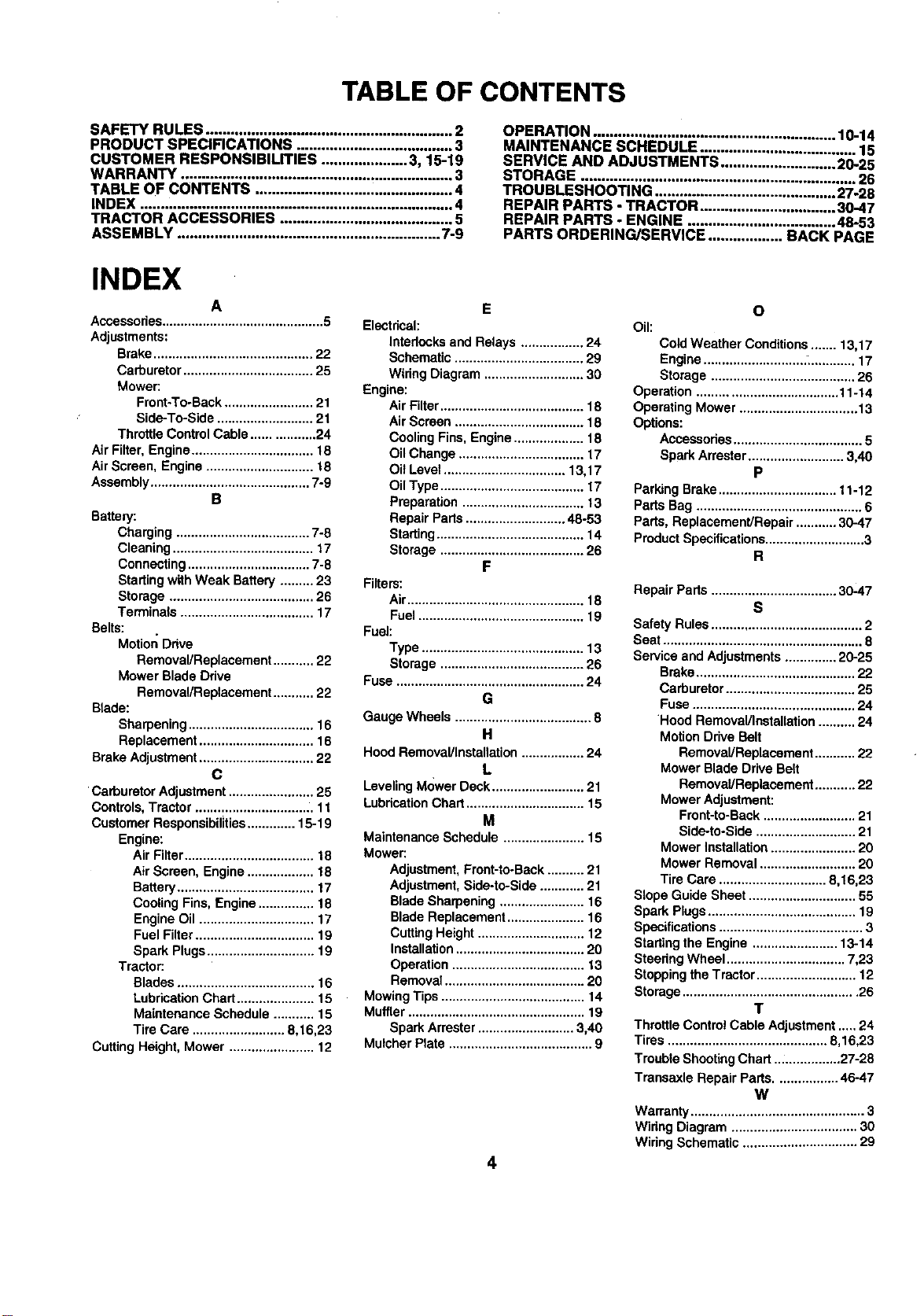
TABLE OF CONTENTS
SAFETY RULES ............................................................ 2
PRODUCT SPECIFICATIONS ...................................... 3
CUSTOMER RESPONSIBILITIES ..................... 3, 15-19
WARRANTY .................................................................. 3
TABLE OF CONTENTS ................................................ 4
INDEX ............................................................................ 4
TRACTOR ACCESSORIES .......................................... 5
ASSEMBLY ................................................................ 7-9
OPERATION ........................................................ 10-14
MAINTENANCE SCHEDULE ...................................... 15
SERVICE AND ADJUSTMENTS ............................ 2025
STORAGE ................................................................... 26
TROUBLESHOOTING ............................................ 27-28
REPAIR PARTS - TRACTOR ................................. 30-47
REPAIR PARTS - ENGINE .................................... 48-53
PARTS ORDERING/SERVICE .................. BACK PAGE
INDEX
A
Accessories............................................ 5
Adjustments:
Brake........................................... 22
Carburetor ................................... 25
Mower:
Front-To-Back........................ 21
Side-To-Side .......................... 21
Throttle ControlCable ................. 24
Air Filter,Engine................................. 18
AirScreen, Engine ............................. 18
Assembly........................................... 7-9
B
Battery:
Charging .................................... 7-8
Cleaning ...................................... 17
Connecting................................. 7-8
Startingwith Weak Battery ......... 23
Storage ....................................... 26
Terminals .................................... 17
Belts:
Motion Drive
Removal/Replacement ........... 22
Mower Blade Ddve
Removal/Replacement........... 22
Blade:
Sharpening.................................. 16
Replacement ............................... 16
Brake Adjustment............................... 22
C
Carburetor Adjustment....................... 25
Controls,Tractor ................................ 11
Customer Responsibilities............. 15-19
Engine:
Air Filter................................... 18
Air Screen, Engine.................. 18
Battery..................................... 17
Cooling Fins,Engine............... 18
EngineOil ............................... 17
Fuel Filter................................ 19
Spark Plugs............................. 19
Tractor:
Blades ..................................... 16
LubricationChart..................... 15
Maintenance Schedule ........... 15
Tire Care ......................... 8,16,23
Cutting Height, Mower ....................... 12
E
Electrical:
Intedocksand Relays ................. 24
Schematic ................................... 29
WiringDiagram ........................... 30
Engine:
Air Filter....................................... 18
Air Screen ................................... 18
Cooling Fins,Engine................... 18
Oil Change .................................. 17
Oit Level................................. 13,17
Oil Type....................................... 17
Preparation................................. 13
Repair Parts........................... 48-53
Starting........................................ 14
Storage ....................................... 26
F
Filters:
Air................................................ 18
Fuel............................................. 19
Fuel:
Type ............................................ 13
Storage ....................................... 26
Fuse ................................................... 24
G
Gauge Wheels ..................................... 8
H
HoodRemoval/Installation................. 24
L
LevelingM<)werDeck ......................... 21
LubdcationChart ................................ 15
M
MaintenanceSchedule ...................... 15
Mower:
Adjustment,Front-to-Back.......... 21
Adjustment,Side-to-Side............ 21
Blade Sharpening ....................... 16
Blade Replacement..................... 16
CuttingHeight ............................. 12
Installation................................... 20
Operation .................................... 13
Removal ...................................... 20
MowingTips ....................................... 14
Muffler................................................ 19
Spark Arrester.......................... 3,40
Mulcher Plate ....................................... 9
4
O
Oil:
Cold Weather Conditions....... 13,17
Engine........................... :_............ 17
Storage ....................................... 26
Operation ...................................... 11-14
Operating Mower ................................ 13
Options:
Accessodes................................... 5
Spark Arrester.......................... 3,40
P
Parking Brake................................ 11-12
Parts Bag ............................................. 6
Pads, Replacement/Repair ........... 30-47
ProductSpecifications........................... 3
R
Repair Parts .................................. 30-47
s
Safety Rules......................................... 2
Seat ...................................................... 8
Serviceand Adjustments.............. 20-25
Brake........................................... 22
Carburetor................................... 25
Fuse............................................ 24
Hood Removal/Installation.......... 24
MotionDrive Belt
Removal/Replacement........... 22
Mower BladeDrive Belt
Removal/Replacement........... 22
Mower Adjustment:
Frent-to-Back ......................... 21
Side-to-Side ........................... 21
Mower Installation....................... 20
Mower Removal .......................... 20
Tire Care ............................. 8,16,23
Slope Guide Sheet ............................. 55
Spark Plugs........................................ 19
Specifications....................................... 3
Startingthe Engine ....................... 13-14
Steedng Wheel ................................ 7,23
StoppingtheTractor ........................... 12
Storage............................................... 26
T
ThrottleControlCable Adjustment..... 24
Tires ........................................... 8,16,23
Trouble ShootingChart .................. 27-28
Transaxle Repair Parts................. 46-47
W
Warranty............................................... 3
Widng Diagram .................................. 30
Wiring Schematic ............................... 29
ACCESSORIES AND ATTACHMENTS
These accessoriesand attachmentswere availablethroughmostSears retailoutletsandservicecenterswhen thetractorwaspurchased.
MostSears stores can orderthese items foryou when youprovidethe modelnumber ofyour tractor,
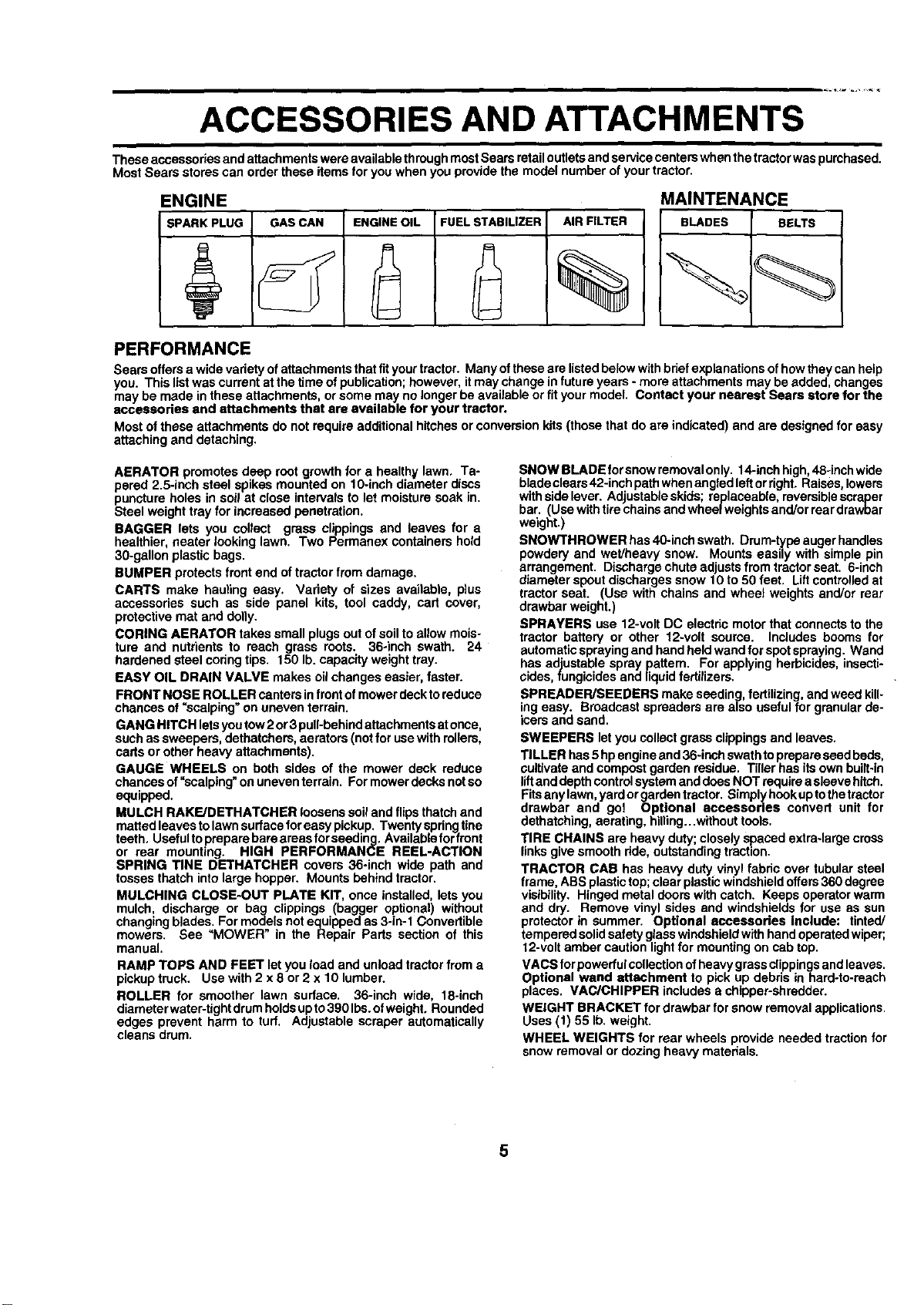
ENGINE
SPARKPLUG
GASCAN ENGINEOIL FUELSTABILIZER
AIRFILTER
%
MAINTENANCE
BLADES BELTS
PERFORMANCE
Sears offersa widevarietyofattachmentsthatfityourtractor. Many oftheseare listedbelowwithbriefexplanationsofhowthey canhelp
you. This listwas currentst the timeofpublication;however,itmay change infuture years- more attachments may beadded, changes
may be made in these attachments, orsome may nolonger be available orfit your model. Contact your nearest Sears store for the
accessories and attachments that are available for your tractor.
Mostof these attachments do not requireadditionalhitchesorconversionkits(thosethat do are indicated) and are designedfor easy
attachingand detaching.
AERATOR promotesdeep root growthfor a healthy lawn, Ta-
pered 2.5-inch steel spikes mountedon 10-inch diameter discs
puncture holes in soil at close intervalsto let moisture soak in.
Steel weight trey for increasedpenetration.
BAGGER lets you collect grass clippings and leaves for a
healthier,nearer looking lawn. Two Permanex containershold
30-gallon plastic bags.
BUMPER protectsfront end oftractor from damage.
CARTS make hauling easy. Variety of sizes available, plus
accessories such as side panel kits, tool caddy, cart cover,
protective mat and dolly.
CORING AERATOR takes small plugsout ofsoilto allowmois-
ture and nutrients to reach grass roots. 36-inch swath. 24
hardened steel coringtips. 150 lb. capacityweight tray.
EASY OIL DRAIN VALVE makes oilchanges easier, faster.
FRONT NOSE ROLLER canters infront ofmowerdecktoreduce
chances of =scalping" on uneven terrain.
GANG HITCH letsyoutow2or3 pull-behindattachmentsatonce,
suchas sweepers,dethatchers,aerators(notfor usewithrollers,
carts or other heavy attachments).
GAUGE WHEELS on both sides of the mower deck reduce
chances of=scalping"onuneventerrain. Formowerdecksnotso
equipped.
MULCH RAKE/DETHATCHER loosenssoiland flips thatchand
mattedleaves tolawnsurfaceforeasy pickup. Twentyspringtine
teeth. Usefultoprepare bareareasforseeding. Availableforfront
or rear mounting. HIGH PERFORMANCE REEL-ACTION
SPRING TINE DETHATCHER covers 36-inch wide path and
tosses thatch intolarge hopper. Mountsbehindtractor.
MULCHING CLOSE-OUT PLATE KIT, once installed, letsyou
mulch, discharge or bag clippings (bagger optional) without
changingblades. For modelsnot equippedas3-in-1 Convertible
mowers. See "MOWER in the Repair Parts section of this
manual.
RAMP TOPS AND FEET let you load and unload tractorfroma
pickuptruck. Usewith 2 x 8 or 2 x 10 lumber.
ROLLER for smoother lawn surface. 36-inch wide, 18-inch
diameter water-tightdrumholdsupto390Ibs.of weight,Rounded
edges prevent harm to turf. Adjustable scraper automatically
cleans drum.
SNOW BLADE forsnowremovalonly. 14-inchhigh,48-inchwide
bladeclears42-inchpathwhenangledleftorfight. Raises,lowers
withsidelever. Ad ustableskids; replaceable, reversiblescraper
bar. (Use witht recha nsand wbeelwe ghtsand/or reardrawbar
weight.)
SNOWTHROWER has40-inchswath. Drum-typeaugerhandles
powdery and wet/heavy snow. Mounts easily with simple pin
arrangement. Dischargechuteadjustsfrom tractorseat. 6-inch
diameter spoutdischargessnow 10 to50 feet. Liffcontrolledat
tractor seat. (Use with chains and wheel weights and/or rear
drawbar weight.)
SPRAYERS use 12-voltDC electric motorthat connectsto the
tractor battery or other t2-voit source. Includes booms for
automaticsprayingand handheld wandforspotspraying.Wand
has adjustable spray pattern. For applyingherbicides, insecti-
cides,fungicidesand liquidfertilizers.
SPREADER/SEEDERS make seeding,fertilizing, andweed kill-
ing easy. Broadcast spreaders are also usefulfor granularde-
icersand sand.
SWEEPERS letyou collectgrass clippingsand leaves.
TILLER has5 hpengineand36-inchswathtoprepareseed beds,
cultivateand compostgarden residue. Tiller hasits own built-in
liftanddepthcontrolsystemanddoesNOT requireasleevehitch.
Fitsanylawn,yardorgardentractor. Simplyhookuptothetractor
drawber and go! Optional accessories convert unit for
dethatching,aerating, hilling...withouttools.
TIRE CHAINS are heavy duty;closely Spacedextra-largecross
linksgivesmooth fide, outstandingtraction.
TRACTOR CAB has heavy duty vinylfabric over tubular steel
frame, ABSplastictop;clearplasticwindshieldoffers360degree
visibility. Hinged metal doors withcatch. Keeps operatorwarm
and dry. Remove vinyl sides and windshieldsfor use as sun
protectorin summer. Optional accessories include: tinted/
temperedsolidsafetyglasswindshieldwithhand operatedwiper;
12-voltamber caution lightfor mounting on cabtop.
VACS for powerfulcollectionofheavygrassclippingsandleaves.
Optional wand attachment to pick up debris in hard-to-reach
places. VAC/CHIPPER includesa chipper-shredder.
WEIGHT BRACKET for drawbar for snow removalapplications.
Uses (1) 55 Ib. weight.
WHEEL WEIGHTS for rear wheels provide needed tractionfor
snowremovalor dozingheavy materials.
5
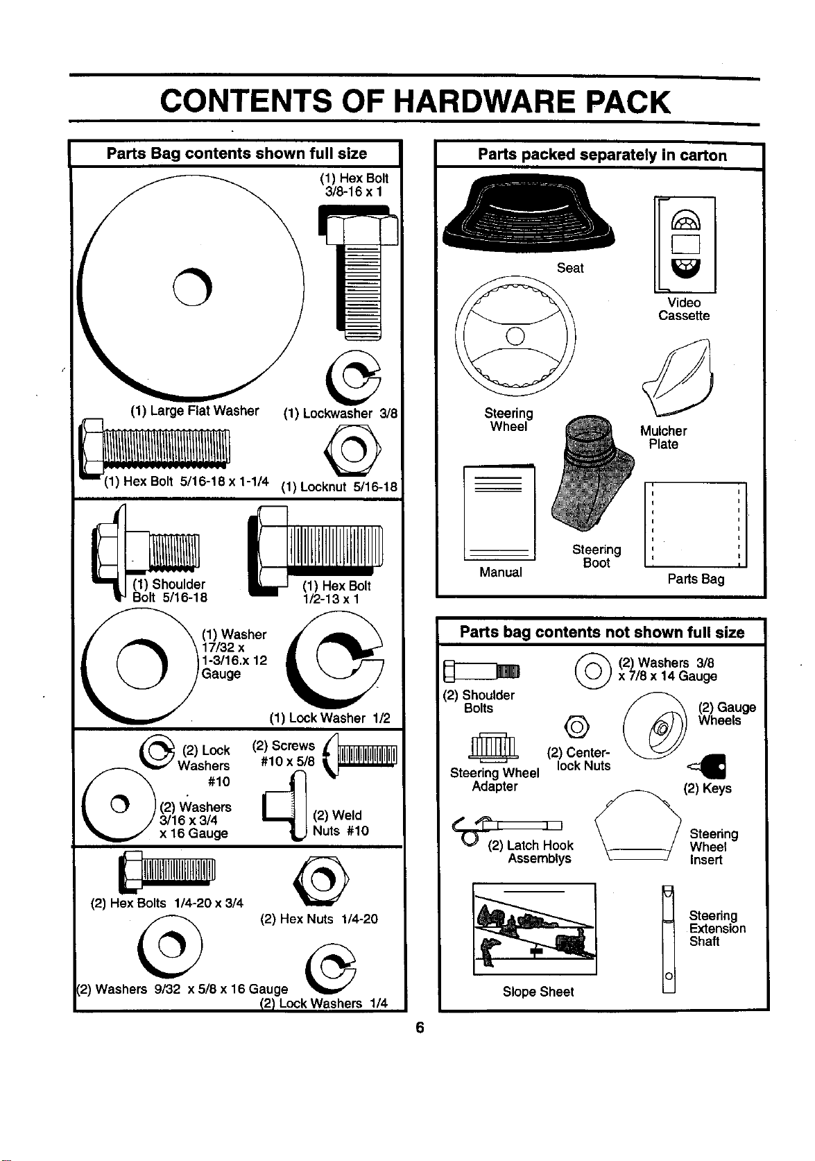
CONTENTS OF HARDWARE PACK
Parts Bag contents shown full size
(1) Hex Bolt
3/8-16 x 1
(1) Large Flat Washer (1) Lockwasher 3/8
1;:He':x:Bo;:t:5:i:16:::;:8x1-I/4(1)Locknut 5/16-18
(1) Shoulder (1) Hex Bolt
Bolt 5/16-18 1/2-13 x I
(1) Washer _.
17/32 x
1-3/16.x 12
Gauge (1) Lock Washer 1/2
__._ (2) (2) Screws
Lock
#10 x 5/8
Was%
| __J }(2) V_/ashers
_i= / 3/16 x 3/4
x 16 Gauge
(2) Hex Bolts 1/4-20 x 3/4
@
(2) Hex Nuts 1/4-20
(2) Washers 9/32 x 5/8 x 16 Gauge
12)LockWashers 1/4
Parts packed separately in carton
Steering
Wheel
Manual
Seat
Steering
Boot
Video
Cassette
Mulcher
Plate
Parts Bag
Parts bag contents not shown full size
(2) Shoulder
Bolts
(_(2) Washers 3/8
x 7/8 x 14 Gauge
(2) Gauge
Q Wheels
_ (2) Center-
Steering Wheel lockNuts
Adapter (2) Keys
k
Assemblys
Steering
Wheel
Insert
Slope Sheet
Steering
Extension
Shaft
6
ASSEMBLY
Your new tractorhasbeen assembledat thefactorywithexceptiono4those partsleft unassembledfor shippingpurposes.
To ensuresafe and properoperationofyourtractorallpartsand hardwareyou assemble mustbetightenedsecurely. Use
the correcttoolsas necessaryto insurepropertightness.
TOOLS REQUIRED FOR ASSEMBLY
Asocketwrenchset willmake assemblyeasier. Standard
wrenchsizes are listed.
(1) 3/4" Socketw/drive rachet
(2) 7/16" wrenches PhillipsScrewdriver
(2) 1/2" wrenches Tire pressuregauge
(1) 9/16" wrench Utilityknife
When right or left hand is mentioned in this manual, it
means when you are in the operating position(seated
behindthe steeringwheel).
TO REMOVE TRACTOR FROM CARTON
UNPACK CARTON
• Remove all accessiblelooseparts and partscartons
from carton(See page 6).
Cut, from topto bottom,along linesonall four corners
of carton,and lay panelsflat.
Check for any additional loose parts or cartonsand
remove.
BEFORE ROLLING TRACTOR OFF SKID
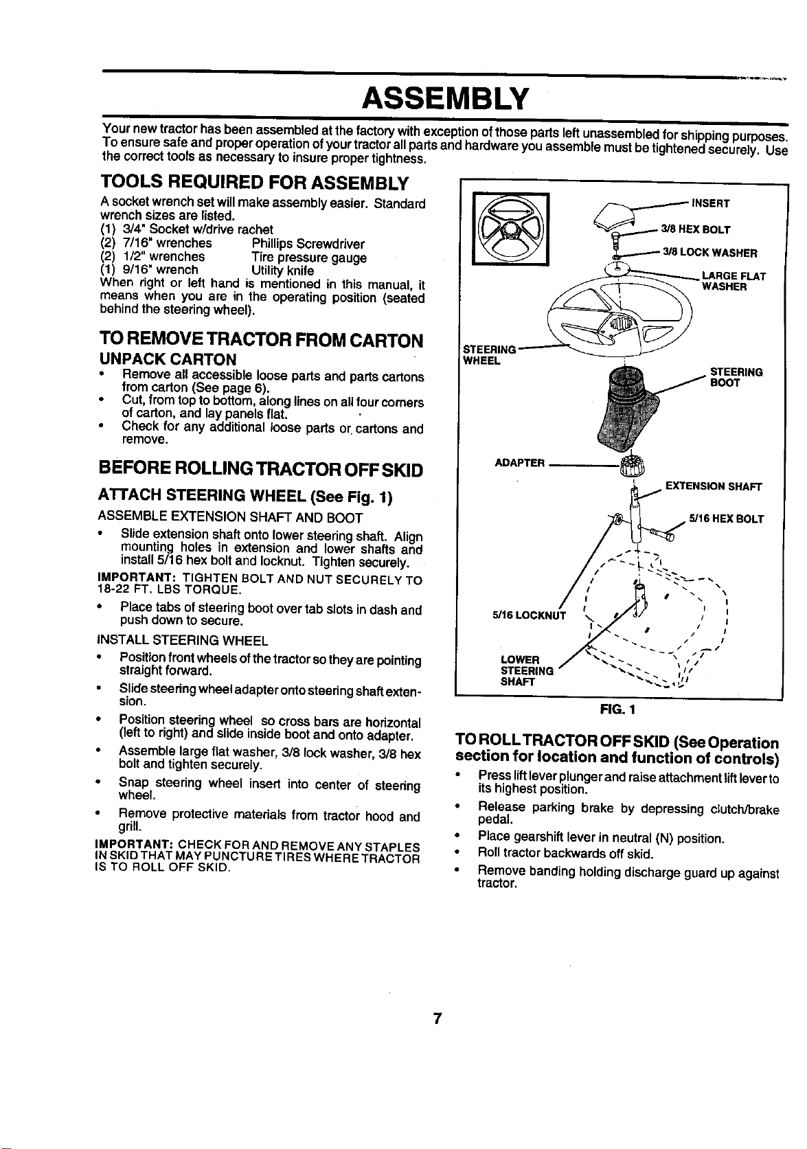
ATFACH STEERING WHEEL (See Fig. 1)
ASSEMBLE EXTENSION SHAFT AND BOOT
• Slideextension shaftonto lower steeringshaft. Align
mounting holes in extension and lower shafts and
install 5/16 hex bolt and Iocknut. Tighten securely,
IMPORTANT: TIGHTEN BOLT AND NUT SECURELYTO
18-22 FT, LBS TORQUE.
• Place tabsof steeringboot over tab slotsindash and
pushdownto secure.
INSTALL STEERING WHEEL
• Positionfront wheelsofthetractorsotheyarepointing
straightforward.
Slidesteeringwheeladapterontosteeringshaftexten-
sion.
• Positionsteering wheel so cross bars are horizontal
(leftto right)and slide insideboot and onto adapter.
• Assemblelargeflat washer, 318lookwasher,318hex
boltand tightensecurely.
• Snap steering wheel insert into center of steering
wheel.
• Remove protective materials from tractor hood and
grill.
IMPORTANT: CHECK FOR AND REMOVE ANY STAPLES
INSKIDTHATMAYPUNCTURE TIRESWHERETRACTOR
IS TO ROLLOFF SKID.
__3/8jE INSERT
X BOLT
LOCK WASHER
LARGE FLAT
WASHER
:STEERING'
WHEEL
STEERING
ADAPTER_
EXTENSION SHAFT
5/16 HEX BOLT
5/16LOCKNUT
LOWER
STEERING
SHAFt"
FIG. 1
TO ROLLTRACTOR OFF SKID (See Operation
section for location and function of controls)
• Pressliftleverplungerand raiseattachmentliftleverto
itshighestposition.
• Release parking brake by depressing clutch/brake
pedal.
• Place gearshift lever in neutral (N) position,
Roll tractor backwards off skid.
• Remove banding holding discharge guard up against
tractor.
7
ASSEMBLY
HOW TO SET UP YOUR TRACTOR
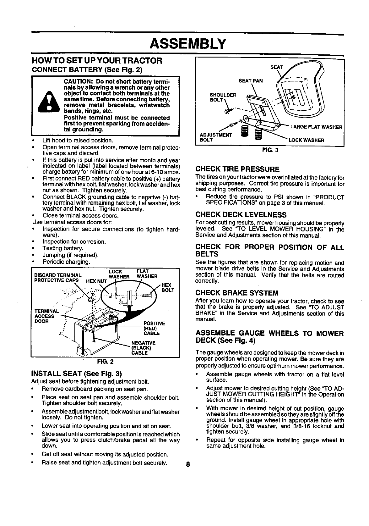
CONNECT BA'rrERY (See Fig. 2)
CAUTION: Do not short battery termi-
nals byallowing a wrench or any other
object to contact both terminals at the
same time. Before connecting battery
remove meta bracelets, wristwatch
bands, rings, etc.
Positive terminal must be connected
first to prevent sparking from acciden-
tal grounding.
Lifthoodto raised position.
Open terminalaccess doors, remove terminal protec-
tive caps and discard.
If this battery is put into service after month and year
indicated on label (label located between terminals)
charge battery for minimum of one hour at6-10 amps.
• First connect RED battery cable to positive (+)battery
terminal with hexbolt,flat washer, lock washer and hex
nut as shown. Tighten securely.
Connect BLACK grounding cable to negative (-) bat-
tery terminal with remaining hex bolt, flat washer, lock
washer and hex nut. Tighten securely.
Close terminal access doors.
Use terminal access doors for:
• Inspection for secure connections (to tighten hard-
ware).
• Inspection for corrosion.
• Testing battery.
• Jumping (if required).
• Pedodic charging.
DISCARD TERMINAL
PROTECTIVE CAPS HEX NUT
ACCESS
DOOR
LOCK FLAT
WASHER WASHER
PosmvE
(RED)
CABLE
NEGATIVE
(BLAC_
CABLE
FIG. 2
INSTALL SEAT (See Fig. 3)
Adjustseat beforetighteningadjustmentbolt.
• Remove cardboard packingon seat pan.
• Place seat on seat pan and assemble shoulderbolt.
Tightenshoulderboltsecurely.
• Assembleedjustment bolt, lockwasher and flatwasher
loosely. Do not tighten.
Lower seat into operating position and sit on seat.
Slide seat until acomfortable position is reached which
allows you to press clutch/brake pedal all the way
down.
Get off seat without moving its adjusted position.
• Raise seat and tighten adjustment bolt securely.
SEAT
SEAT PAN
SHOULDER
BOLT
r WASHER
ADJUSTMENT
BOLT LOCK WASNER
FIG. 3
CHECK TIRE PRESSURE
The tiresonyourtractorwereoverinflatedatthefactoryfor
shippingpurposes. Correcttire pressure is importantfor
bestcuttingperformance.
Reduce tire pressure to PSI shown in "PRODUCT
SPECIFICATIONS" on page 3 ofthis manual.
CHECK DECK LEVELNESS
Forbestcuttingresults,mowerhousingshouldbe propedy
leveled, See "TO LEVEL MOWER HOUSING" in the
Service and Adjustmentssectionofthis manual.
CHECK FOR PROPER POSITION OF ALL
BELTS
See the figures that are shownfor replacingmotionand
mower blade ddve belts in the Service and Adjustments
sectionof this manual. Verify that the belts are routed
correctly.
CHECK BRAKE SYSTEM
Afteryou learn how tooperate yourtractor, checkto see
that the brake is properlyadjusted. See "TO ADJUST
BRAKE" in the Service and Adjustmentssection of this
manual,
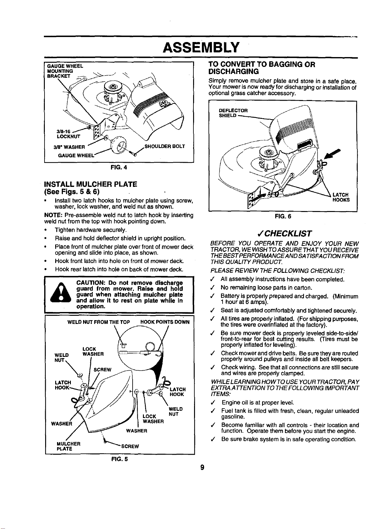
ASSEMBLE GAUGE WHEELS TO MOWER
DECK (See Fig. 4)
The gauge wheelsare designed to keepthe mowerdeck in
proper positionwhen operatingmower. Be sure they are
properlyadjustedtoensureoptimummowerperformance.
• Assemble gauge wheels with tractor on a flat level
surface.
Adjustmower todesired cuttingheight (See "TO AD-
JUST MOWER CU'I-]'ING HEIGHT" inthe Operation
sectionofthis manual).
With mower in desired heightof cut position gauge
whee sshouldbeassembledsotheyareslightlyoffthe
ground.Install gauge wheel in appropriateholewith
shoulder bolt, 3/8 washer, and 3/8-16 lecknut and
tighten securely.
Repeat for opposite side installing gauge wheel in
same adjustment hole.
ASSEMBLY
GAUGE WHEEL
MOUN_NG
BRACKET
\
3/8-16
LOCKNUT
_8"WASHER
GAUGE
_SHOULDER BOLT
FIG. 4
INSTALL MULCHER PLATE
(See Figs. 5 & 6)
Install two latch hooksto mulcher plate using screw,
washer, lockwasher, and weld nutas shown.
NOTE: Pre-assemble weld nut to latch hookby inserting
weld nut fromthe top with hookpointingdown.
• Tighten hardware securely.
• Raise and holddeflectorshield in uprightposition.
• Place frontof mulcher plate over frontof mowerdeck
opening and slide intoplace, as shown.
• Hook frontlatch intohole on frontof mower deck.
• Hook rear latch intoholeon backof mower deck.
CAUTION: Do not remove discharge
guard from mower. Raise and ho|d
guard when attaching mulcher plate
and allow it to rest on plate while in
operation.
WELD NUT FROM THE TOP HOOK POINTS DOWN
LOCK
WELD WASHER
NUT_ SCREW
LATCH
HOOK'--..
HOOK
WASHER
MULCHER
PLATE
LOCK
WASHER
WASHER
'_""_SCREW
WELD
NUT
TO CONVERTTO BAGGING OR
DISCHARGING
Simply remove mulcher plate and store in a safe place.
Your mowerisnow readyfor dischargingorinstallationof
optionalgrasscatcher accessory.
DEFLECTOR
HOOKS
FIG. 6
,/CHECKLIST
BEFORE YOU OPERATE AND ENJOY YOUR NEW
TRACTOR, WE WISH TOASSURE THAT YOURECEIVE
THEBEST PERFORMANCE ANDSATISFACTION FROM
THIS QUALITY PRODUCT.
PLEASE REVIEW THE FOLLOWING CHECKLIST:
,/ All assemblyinstructionshave been completed.
,/ No remaininglooseparts in carton.
/ Batteryisproperlyprepared and charged. (Minimum
1 hourat 6 amps).
•/ Seat isadjusted comfortablyand tightened securely.
,/ Alltiresare properlyinflated. (Forshippingpurposes,
the tires were overinflatedat the factory).
,/ Be sure mower deck isproperlyleveledside-to-side/
front-to-rearfor best cutting results. (Tires mustbe
properlyinflatedfor leveling).
,/ Check mower anddrivebelts. Besuretheyare routed
properlyaround pulleysand insideall belt keepers.
,/ Check wiring. See thatallconnectionsarestillsecure
and wires are properlyclamped.
WHILELEARNING HOW TOUSE YOUR TRACTOR, PAY
EXTRA ATTENTION TOTHE FOLLOWING IMPORTANT
ITEMS:
•/ Engine oil isat properlevel
,/ Fuel tank is filledwith fresh,clean, regularunleaded
gasoline.
,/ Become familiar with all controls- their locationand
function. Operate them beforeyou startthe engine.
/ Be sure brake system isin safe operatingcondition.
FIG. 5
9
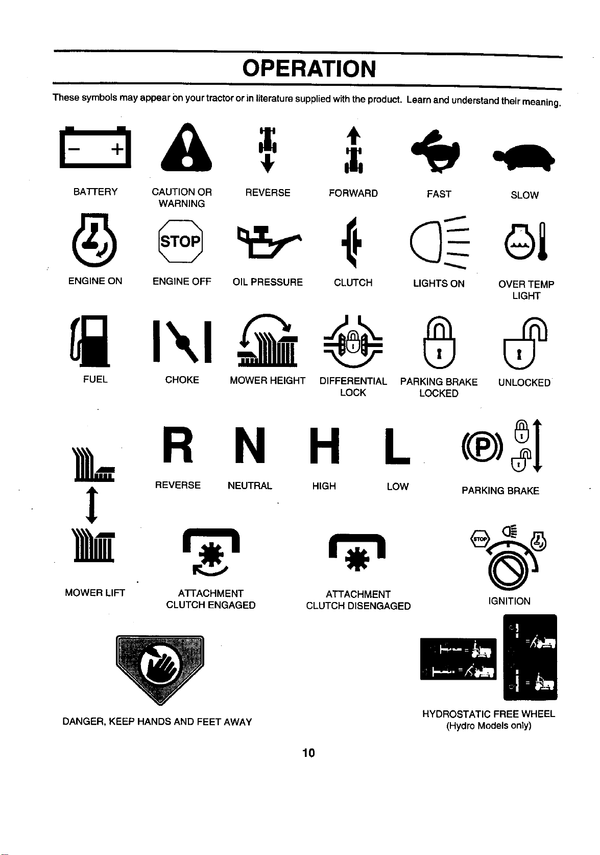
OPERATION
These symbolsmay appearOnyourtractororinliteraturesuppliedwiththe product. Learnand understandtheirmeaning.
BATFERY CAUTION OR REVERSE FORWARD FAST SLOW
WARNING
ENGINE ON ENGINE OFF OIL PRESSURE CLUTCH LIGHTS ON OVER TEMP
LIGHT
FUEL CHOKE MOWER HEIGHT DIFFERENTIAL PARKING BRAKE UNLOCKED
LOCK LOCKED
L R N H L
i REVERSE NEUTRAL HIGH LOW PARKING BRAKE
MOWER LIFT A'I-I'ACHMENT ATTACHMENT
CLUTCH ENGAGED CLUTCH DISENGAGED
IGNITION
DANGER, KEEP HANDS AND FEET AWAY
HYDROSTATIC FREEWHEEL
(Hydro Modelsonly)
10
OPERATION
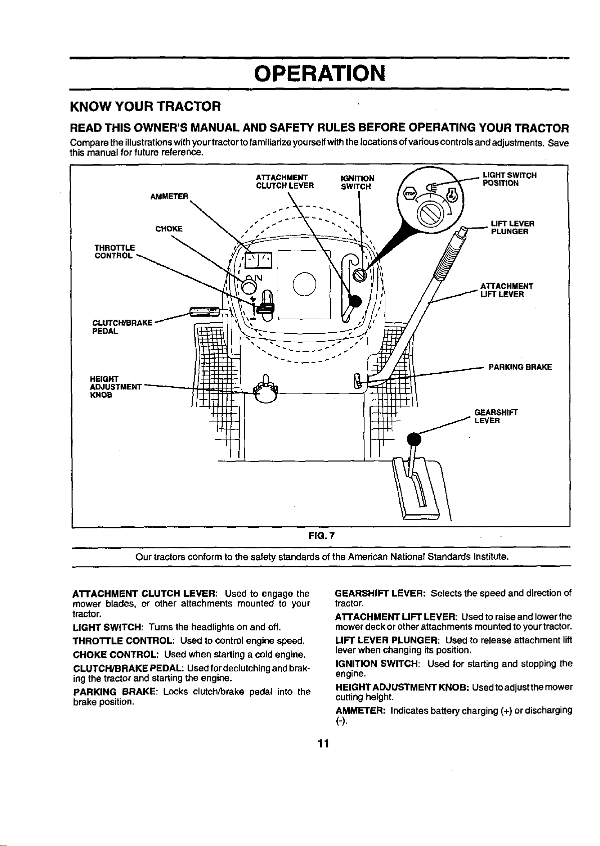
KNOW YOUR TRACTOR
READ THIS OWNER'S MANUAL AND SAFETY RULES BEFORE OPERATING YOUR TRACTOR
Compare theillustrationswithyourtractortofamiliarizeyourselfwiththelocationsofvanouscontrolsandadjustments. Save
this manual for futurereference.
ATTACHMENT IGNITION LIGHT SWITCH
CLUTCH LEVER SWITCH POSITION
AMMETER
-
CHOKE t
LIFT LEVER
THROTTLE
CONTROL
©
ATTACHMENT
CLUTCH/BRAKE
PEDAL
HEIGHT
ADJUSTMENT
KNOB
PARKING BRAKE
GEARSHIFT
FIG. 7
Our tractors conformtothe safetystandardsofthe American NationalStandards Institute.
ATFACHMENT CLUTCH LEVER: Used to engage the
mower blades, or other attachments mounted to your
tractor.
LIGHT SWITCH: Tums the headlightson and off.
THROTFLE CONTROL: Used tocontrolengine speed.
CHOKE CONTROL: Used when startinga coldengine.
CLUTCH/BRAKE PEDAL: Usedfordeclutchingand brak-
ingthe tractorand startingtheengine.
PARKING DRAKE: Locks clutch/brake pedal into the
brake position.
GEARSHIFT LEVER: Selectsthe speed and directionof
tractor.
A'I-rACHMENT LIFT LEVER: Usedto raiseand lowerthe
mowerdeckor otherattachmentsmountedtoyourtractor.
LIFT LEVER PLUNGER: Used to release attachmentlift
leverwhen changing itsposition.
IGNITION SWITCH: Used for startingand stoppingthe
engine.
HEIGHTADJUSTMENT KNOB: Usedtoadjustthemower
cuttingheight.
AMMETER: Indicatesbatterycharging(+) ordischarging
(-).
11
OPERATION
The operation of any tractor can result in foreign objects thrown into the eyes, which can
reauItIn severe eye damage. Always wear safety glasses or eye shields while operating your
tractor or performing any adjustments or repairs. We recommend s wide vision safety mask
over the spectacles or standard safety glasses.
HOW TO USE YOUR TRACTOR
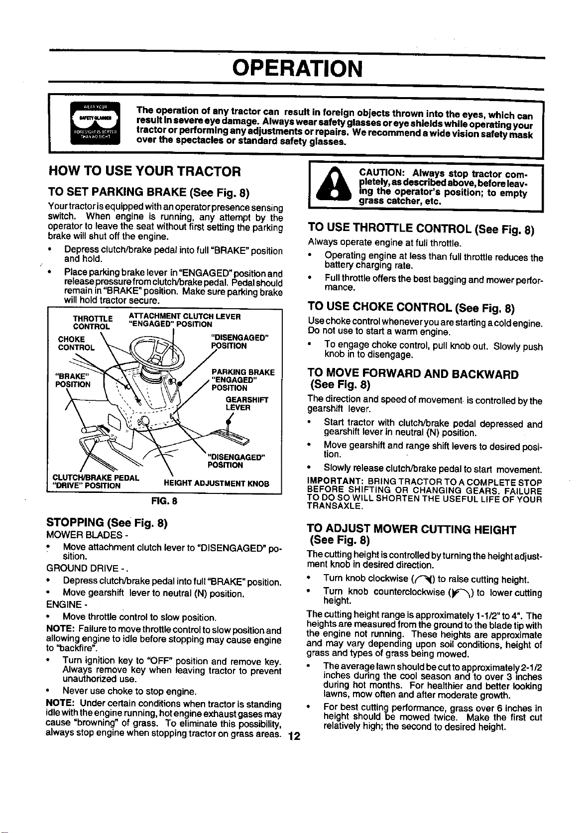
TO SET PARKING BRAKE (See Fig. 8)
Yourtractorisequippedwithanoperatorpresencesensing
switch. When engine is running, any attempt by the
operatorto leave the seat withoutfirst setting the parking
brake willshut offthe engine.
• Depressclutch/brakepedalintofull =BRAKE" position
and hold.
Placeparkingbrake lever in=ENGAGED"positionand
releasepressurefromclutch/brakepedal.Pedalshould
remainin=BRAKE"position.Make sureparkingbrake
willholdtractorsecure.
THROTTLE
CONTROL
ATTACHMENT CLUTCH LEVER
"ENGAGED" POSITION
CHOKE "DISENGAGED"
CONTROL POSITION
PAR_NGBRAKE
"BRAKE"
POSITION POSITION
GEARSHIFT
LEVER
"DISENGAGED"
POSmON
CLUTCH/BRAKE PEDAL
"DRIVE"POSDON
HEIGHT ADJUSTMENT KNOB
FIG. 8
STOPPING (See Fig. 8)
MOWER BLADES -
,, Move attachmentclutchlever to=DISENGAGED" po-
sition.
GROUND DRIVE -.
• Depress clutch/brakepedal intofuit"BRAKE"position.
Move gearshift leverto neutral (N) position.
ENGINE -
• Move throttleControltoslow position.
NOTE: Failuretomovethrottlecontroltoslowposition and
allowingengine toidlebeforestoppingmay cause engine
to "backfire".
Turn ignitionkey to "OFF" positionand remove key.
Always remove key when leaving tractorto prevent
unauthorizeduse.
Never usechoke to stopengine.
NOTE: Under certainconditions when tractor isstanding
idlewiththeengine running,hotengineexhaustgasesmay
cause "browning" of grass. To eliminate this possibility,
always stopenginewhen stoppingtrectoron grassareas. 12
{_ CAUTION: Always stop tractor com-
pletely, asdescribed above, beforeleav-
ing the operator's position; to empty
grass catcher, etc.
TO USE THROTTLE CONTROL (See Fig. 8)
Alwaysoperate engine at fullthrottle.
Operatingengineat lessthan fullthrottlereducesthe
batterychargingrate.
• Fullthrottleoffersthe bestbaggingand mowerpedor-
mance.
TO USE CHOKE CONTROL (See Fig, 8)
Usechokecontrolwheneveryouarestartinga coldengine.
Do not useto starta warm engine.
• To engage choke control,pullknobout. Slowlypush
knobinto disengage.
TO MOVE FORWARD AND BACKWARD
(See Fig. 8)
The directionand speed of movement,iscontrolledbythe
gearshift lever.
Start tractor with clutch/brake pedal depressed and
gearshift lever in neut_l (N) position.
• Move gearshiftand rangeshiftleversto desiredposi-
tion.
• Slowly release clutchibreke pedal to start movement.
IMPORTANT: BRING TRACTOR TO A COMPLETE STOP
BEFORE SHIFTING OR CHANGING GEARS. FAILURE
TO DO SO WILL SHORTEN THE USEFUL LIFE OF YOUR
TRANSAXLE.
TO ADJUST MOWER CUTTING HEIGHT
(See Fig. 8)
The cuttingheightiscontrolledbyturningtheheightadjust-
ment knob in desired direction.
• Turn knob clockwise(f_() to raisecuttingheight.
• Turn knob counterclockwise (_)to lowercutting
height.
The cuttingheightrangeisapproximately 1-1/2" to4". The
heights are measuredfrom the ground to the blade tip with
the engine not running. These heights are approximate
and may vary depending upon soilconditions, height of
grass and types of grass being mowed.
• The average lawn should becut to approximately 2-1/2
inches duringthe cool season and to over 3 inches
during hot months. For healthier and better looking
lawns, mow often and after moderate growth.
• For best cuttingpedormance grassover 6 inches in
height shouldbe mowed twice. Make the first cut
relatively high; the secondto desired height.
OPERATION
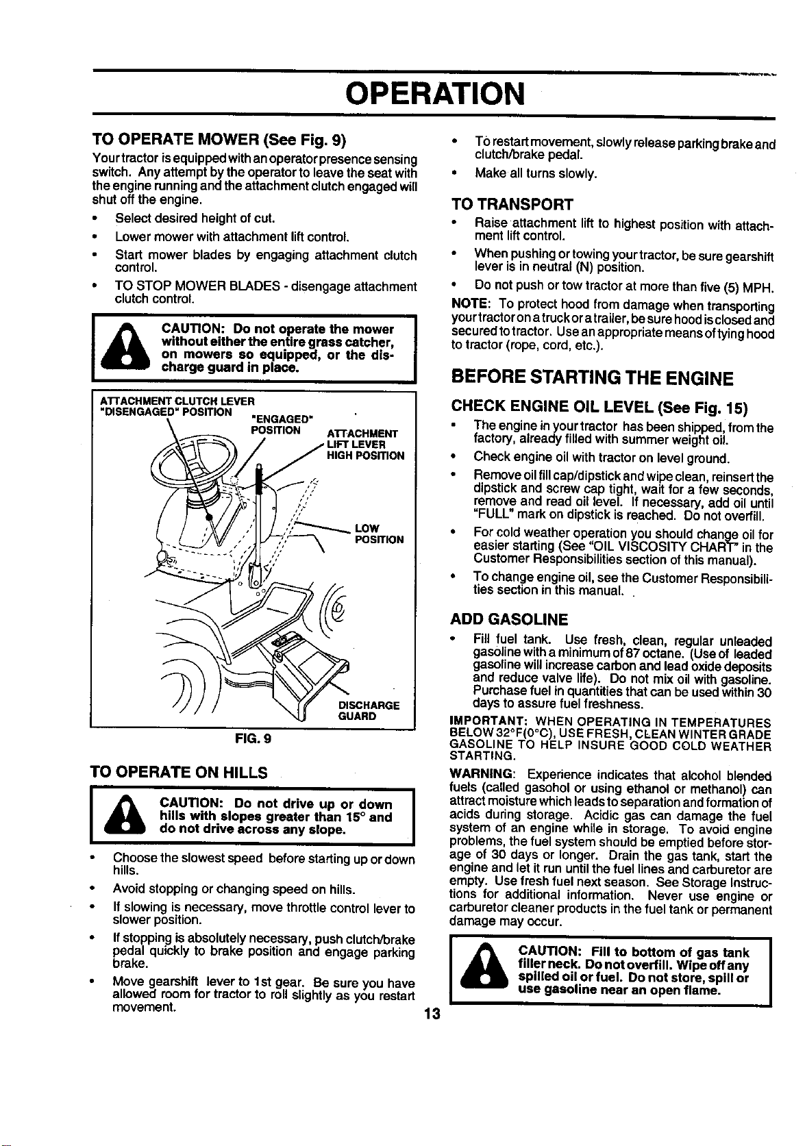
TO OPERATE MOWER (See Fig. 9)
Yourtractorisequippedwithanoperatorpresencesensing
switch. Any attemptbythe operatorto leave the seat with
theengine runningand theattachmentclutchengagedwill
shut offthe engine.
• Select desired heightof cut.
• Lowermower withattachment liftcontrol.
Start mower blades by engaging attachment clutch
control.
• TO STOP MOWER BLADES - disengageattachment
clutchcontrol
CAUTION: Do not operate the mower
without either the entire grass catcher,
on mowers so equipped, or the dis-
charge guard in place.
AI"rACHMENT CLUTCH LEVER
"DISENGAGED" POSITION "ENGAGED"
POSITION ATrACHMENT
_,_ / / LIFT LEVER
_\ )_ / / HIGH POSITION
gwiTI°N
FIG. 9
TO OPERATE ON HILLS
I _ CAUTION: Do not drive up or down I
hills with slopes greater than 15° and
do not drive across any slope.
Choose the slowestspeed before startingup ordown
hills.
Avoidstoppingorchangingspeed on hills.
Ifslowingis necessary,move throttlecontrolleverto
slowerposition.
Ifstoppingisabsolutelynecessary,pushclutch/brake
pedal quickly to brake position and engage parking
brake.
Move gearshift lever to 1st gear. Be sure you have
allowed room for tractor to roll slightly as you restart
movement.
• TOrestartmovement,slowlyreleaseparkingbrakeand
clutch/brakepedal.
• Make allturnsslowly.
TO TRANSPORT
• Raise attachment lift to highestpositionwith attach-
ment liftcontrol.
When pushingortowingyourtractor,besuregearshift
lever is in neutral(N) position.
• Do not pushor towtractorat more than five(5) MPH.
NOTE: To protecthoodfrom damage whentransporting
yourtractoronatruckor atrailer,besurehoodisclosedand
securedtotractor. Useanappropriatemeansoftyinghood
totractor(rope, cord,etc.).
BEFORE STARTING THE ENGINE
CHECK ENGINE OIL LEVEL (See Fig. 15)
The engineinyourtractor hasbeen shipped,fromthe
factory,alreadyfilledwith summerweightoil.
• Check engine oilwithtractoron level ground.
• Remove oilfillcap/dipstickandwipeclean,reinsertthe
dipstickand screwcap tight, wait for a few seconds,
remove and read oil level. If necessary,add oiluntil
"FULL"markon dipstickis reached. Do notoverfill.
• Forcoldweather operationyou shouldchangeoilfor
easier starting(See "OIL VISCOSITY CHART"in the
Customer Responsibilitiessectionofthismanual).
• To change engineoil,see the CustomerResponsibili-
ties sectionin thismanual.
ADD GASOLINE
• Fill fuel tank. Use fresh, clean, regular unleaded
gasolinewithaminimumof87octane. (Useof leaded
gasolinewillincreasecarbon and lead oxidedeposits
and reducevalve life). Do not mix oilwith gasoline.
Purchasefuel in quantitiesthatcan be usedwithin30
daystoassure fuel freshness.
IMPORTANT: WHEN OPERATING IN TEMPERATURES
BELOW32°F(0°C), USEFRESH, CLEANWINTERGRADE
GASOLINE TO HELP INSURE GOOD COLD WEATHER
STARTING.
WARNING: Experience indicates that alcohol blended
fuels (called gasehol or using ethanol or methanol) cart
attract moisturewhichleadstoseparationandformation of
acids during storage. Acidic gas can damage the fuel
system of an engine while in storage. To avoid engine
problems,thefuel system shouldbe emptiedbeforestor-
age of 30 days or longer. Drain the gas tank, startthe
engineand letitrun untilthefuel linesand carburetorare
empty. Use freshfuel nextseason. See StorageInstruc-
tions for additional information. Never use engine or
carburetorcleaner productsinthe fuel tank or permanent
damage may occur.
I
CAUTION: Fill to bottom of gas tank |
filler neck. Do not overfill. Wipe offany
I
spilled oil or fuel. Do not store, spill or
use gasoline near an open flame.
13
OPERATION
TO START ENGINE (See Fig. 8)
When startingthe engine for the firsttimeor ifthe engine
hasrunoutof fuel, it willtake extra crankingtimeto move
fuel from the tank to the engine.
• Sit on seat in operating position, depress clutch/brake
pedal and set parking brake.
• Place gear shift lever in neutral (N) position.
Move attachmentclutch to "DISENGAGED" position.
• Move throttle control to fast position
Pull choke control out for a cold engine startattempt.
For a warm engine start attempt the choke control may
not be needed.
Note: Before starting, read the warm and cold starting
procedures below.
Insertkeyinto ignitionandtum keyclockwiseto=START"
position and release key as soon asengine starts. Do
not run starter continuously for more than fifteen sec-
onds per minute. If the engine does not start after
several attempts, push choke control in, wait a few
minutes and try again. If enginestill does notstart, pull
the choke control out and retry.
WARM WEATHER STARTING (50° Fand above)
• When engine starts, slowlypushchoke controlin until
the engine begins to run smoothly. If the engine starts
to run roughly, pull the choke control out slightly for a
few seconds and then continue to push the control in
slowly.
• Theattachmentsandgrounddrive cannowbe used. If
the enginedoes notacceptthe load,restart the engine
and allow itto warm up for one minute using the choke
as described above.
COLD WE.ATHER STARTING (50° F and below)
• When engine starts,slowly push chokecontrolin until
the engine begins to run smoothly. Continue to push
thechoke controlin smallstepsallowingthe engineto
accept small changes in speed and load, until the
choke control is fully in, If the engine starts to run
roughly,pull the choke controlout slightlyfor a few
seconds and then continue to push the control in
slowly. This may require an engine warm-up period
from several seconds to severa/minutes, depending
on the temperature.
• The attachments can be used dudng theenginewarm-
up period and may require the chokecontrol be pulled
out slightly.
NOTE: If at a high altitude (above 3000 feet) or in cold
temperatures (below 32 F) the carburetorfuel mixture may
need to be adjusted for best engine performance. See "TO
ADJUST CARBURETOR" in the Service and Adjustments
sectionofthis manual.
MOWING TIPS
• Tirechainscannotbeusedwhenthemowerhousingis
attachedto tractor.
• Mower should be propedy leveled for best mowing
performance. See "TO LEVEL MOWER HOUSING" in
theService and Adjustmentssectionof thismanual.
• The left hand sideof mower shouldbe used fortdm-
ming.
Drive so that clippingsare dischargedontothe area
thathasbeen cut. Have thecutareatothe rightofthe
tractor. This will resultin a moreeven distributionof
clippingsand more uniformcutting.
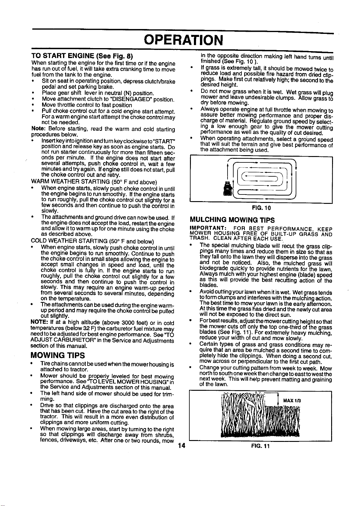
When mowing large areas, startbyturning to the right
so that clippings will discharge away from shrubs,
fences, driveways, etc. After one or two rounds, mow
in the oppositedirectionmakingleft hand turnsuntil
finished (See Fig. 10 ).
If grass is extremelytall, it,should be mowed twice to
reduce load and possible Tirehazard from dded clip-
pings. Make first cutrelatively high; the second to the
desired height.
Do not mow grass when it iswet. Wet grasswillplug
mower and leave undesirable clumps. Allow grass to
dry before mowing,
Always operate engine at full throttle when mowing to
assure better mowing performance and proper dis-
charge of material. Regulate ground speed by select-
ing a low enough gear to give the mower cutting
performance as well as the quality of cut desired.
When operating attachments, select a greund speed
that will suit the terrain and give best performance of
the attachment being used.
1
FIG. 10
MULCHING MOWING TIPS
IMPORTANT: FOR BEST PERFORMANCE, KEEP
MOWER HOUSING FREE OF BUILT-UP GRASS AND
TRASH. CLEAN AFTER EACH USE.
• The specialmulchingblade wilt recutthe grass clip-
pingsmany timesand reduce them in size so thatas
theyfallontothelawntheywilldisperseintothegrass
and not be noticed. Also, the mulched grass will
biodegradequicklyto providenutrientsfor the lawn.
Always mulchwithyourhighestengine (blade)speed
as this will provide the best recuttingaction of the
blades.
• Avoidcuttingyourlawnwhenitiswet. Wetgrasstends
toformclumpsandinterfereswiththemulchingaction.
The besttimetomow yourlawnistheearly afternoon.
Atthistimethegrasshasdriedandthe newlycutarea
willnot be exposedto thedirectsun.
• Forbestresults,adjustthemower cuttingheightsothat
the mowercuts offonlythe top one-thirdofthe grass
blades(See Fig. 11). Forextremely heavy mulching,
reduceyourwidthofcut and mowslowly.
• Certain types of grass and grassconditionsmay re-
quirethatan area be mulcheda secondtimeto com-
pletelyhidethe clippings. When doinga secondcut,
mowacrossor perpendicularto thefirstcutpath.
Change yourcuttingpatternfromweek toweek. Mow
northtosouthoneweekthenchangetoeasttowestthe
next week. This willhelppreventmattingand graining
of the lawn.
.,x,o
14 FIG. 11
CUSTOMER RESPONSIBILITIES
.A,NTENANCESCHEOULE
F,LL'"OATEB
REGULAR SERVICE CEDATES
Check Brake Operation _
Check Tire Pressure
T Cheek for Loose Fasteners 1_7 V'
Sharpen/Replace Mower Blades I_,=
Chart If
Lubrication
TO Check Battery Level/Recharge
Clean Battery and Terminals I_
R Check Transaxle Cooling k/
Adjust Blade BeLt(s)Tension q_#'s
Adjust Motion Ddve Belt(s) Tension _Jl's
Check Engine Oil Level I1 / V w
Change Engine Oil . _1,2.3 _1_
Clean Air Filter _2
E Clean Air Screen
1#'2
G Inspect Muffler/Spark Arrester I,/
I Replace Oil Filter (If equipped) 1_1,2
N Clean Engine Cooling Fins _i
Replace Spark Plug V'
Replace Air Filter Paper Cartridge
Replace Fuel Fitter I_
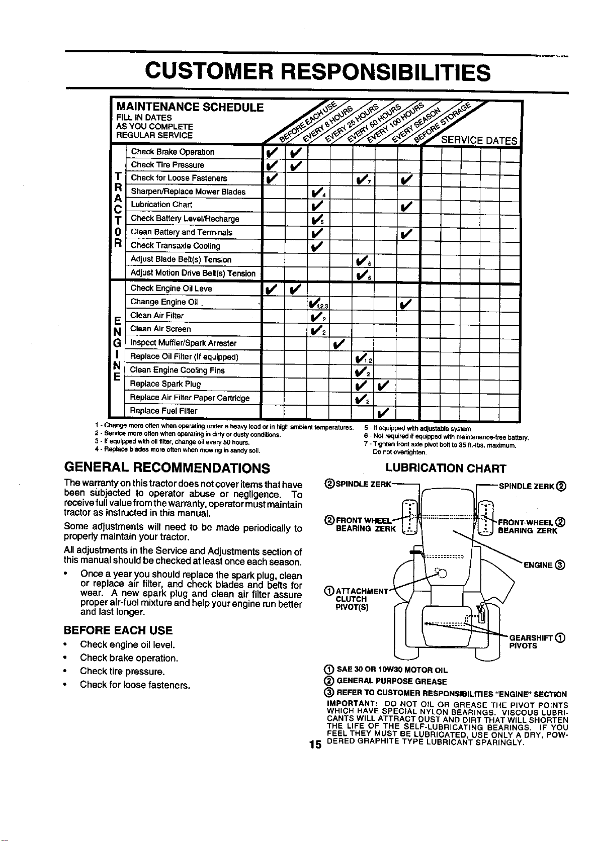
1 - Change more oftenwhen operating under a heavy loador inhigh ambienttemperatures.
2 - Service more oftenwhen operating indirly ordusty conditions.
3 - If equippedwith oil tilter,change oilevery 50 hours.
4 - Replace bladesmore oftenwhen mowingin sandysoil.
5 - If equipped withadjustable system,
6 - Not raquirad ifequipped withmaintenance-free battery.
7 -Tighten front axle pivotbolt to 35 ft.-Ibs, maximum,
DOnotovedighten,
GENERAL RECOMMENDATIONS
The warrantyonthistractor doesnot coveritems thathave
been subjected to operator abuse or negligence. To
receivefullvaluefrom thewarranty,operatormust maintain
tractoras instructedin this manual.
Some adjustments will need to be made periodically to
properlymaintain yourtractor.
Alladjustmentsinthe Service and Adjustmentssectionof
thismanualshouldbe checkedatleastonceeach season.
Once a year you shouldreplacethe sparkplug,clean
or replace air filter, and check blades and belts for
wear. A new spark plug and clean air filter assure
proper air-fuel mixture and help your engine run better
and last longer.
BEFORE EACH USE
Check engineoil level.
Check brake operation,
Check tire pressure.
Check for loosefasteners.
LUBRICATION CHART
(_ SPINDLE ZERK-_®FRONTWHEEL 't-- I1:::::::::::::::::::::
BEARING ZERK
(_ ATTACHMENT" !
CLUTCH
PIVOT(S)
(_) SAE 30 OR IOW30 MOTOR OIL
(_ GENERAL PURPOSE GREASE
_ SPINDLE ZERK (_)
;.,
(_) REFER TO CUSTOMER RESPONSIBILITIES "ENGINE"
SECTION
IMPORTANT: DO NOT OIL OR GREASE THE PIVOT POINTS
WHICH HAVE SPECIAL NYLON BEARINGS. VISCOUS LUBRI-
CANTS WILL ATTRACT DUST AND DIRT THAT WILL SHORTEN
THE LIFE OF THE SELF-LUBRICATING BEARINGS. IF YOU
FEEL THEY MUST BE LUBRICATED, USE ONLY A DRY, POW-
lS OERED GRAPHITE TYPE LUBRICANT SPARINGLY.
CUSTOMER RESPONSIBILITIES
TRACTOR
Alwaysobservesafety ruleswhen performingany mainte-
nance.
BRAKE OPERATION
Iftractorrequiresmorethan six (6) feet stoppingdistance
athighspeed inhigbestgear,thenbrake mustbe adjusted.
(See 'I"O ADJUST BRAKE" in the Service and Adjust-
ments section of this manual).
TIRES
• Maintain properair pressure in all tires (See "PROD-
UCT SPECIFICATIONS" on page 3 of this manual).
Keep tires free ofgasoline, oil, or insect control chemi-
cals which can harm rubber.
,. • Avoid stumps, stones, deep ruts, sharp objects and
other hazards that may cause tire damage.
NOTE: To seal tire punctures and prevent flat tires due to
slow leaks, tire sealant may be purchased from your local
parts dealer. Tire sealant also prevents tire dry rot and
corrosion.
BLADE CARE
Forbest resultsmower blades mustbe kept sharp, Re-
place bent or damaged blades,
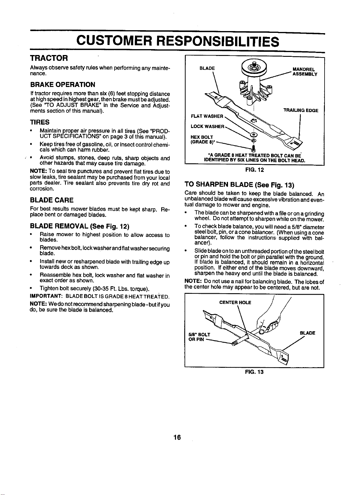
BLADE REMOVAL (See Fig. 12)
Raise mower to highest positionto a_lowaccess to
blades.
• Removehexbolt, leckwasherandflatwashersecuring
blade.
• Install newor resharpenedblade withtrailingedge up
towardsdeck as shown.
Reassemble hex bolt, lock washer and flat washer in
exact order as shown.
• Tighten boltsecurely(30-35 Ft. Lbs.torque).
IMPORTANT: BLADEBOLTISGRADE8 HEATTREA]'ED.
NOTE: Wedo notrecommendsharpeningblade- but ifyou
do, be sure the blade isbalanced.
BLADE _ MANDREL
IJA°SEMDLV
TRAIUNG EDGE
FLAT WASHER _ _ I
LOCKWASHER !
HEXeOLT.
GRADE,,
*A GRADE 8 HEAT TREATED BOLT CAN BE
IDENTIFIED BY SIX UNES ON THE BOLT HEAO.
FIG. 12
TO SHARPEN BLADE (See Fig. 13)
Care should be taken to keep the blade balanced. An
unbalancedbladewillcauseexcessivevibrationandeven-
tual damage to mower and engine.
• The bladecanbesharpenedwitha fileorona grinding
wheel. Do not attempttosharpenwhileon the mower.
To checkbladebalance,youwillneed a 5/8"diameter
steelbolt,pin,ora conebelancer. (Whenusinga cone
balancer, follow the instructions-suppliedwith bal-
ancer).
• Slidebladeontoanunthreadedportionofthesteelbolt
orpinand holdthe boltor pinparallelwiththeground.
If blade is balanced, it shouldremain in a horizontal
position. If eitherend ofthe blade movesdownward,
sharpenthe heavyend untilthe blade isbalanced.
NOTE: Do notusea nattforbalancingblade. The lobesof
the center holemay appear tobe centered, butare not.
CENTER HOLE / /
,. ADE
OR PIN _
FIG. 13
16
CUSTOMER RESPONSIBILITIES
BATFERY
Yourtractorhas a batterycharging systemwhichissuffi-
cient for normal use. However, periodicchargingof the
batterywith an automotivechargerwillextend itslife.
Keep battery and terminalsclean.
• Keep battery bolts tight.
Keep small vent holes open.
Recharge at 6-10 amperes for 1 hour,
TO CLEAN BATTERY AND TERMINALS
Corrosion and dirt on the battery and terminals can cause
the battery to "leak" power.
Remove terminalguard.
• DisconnectBLACKbatterycable first then RED bat-
tery cable and removebattery fromtractor.
• Rinse the batterywith plainwater and dry.
• Cleanterminalsandbatterycable endswithwirebrush
untilbright.
• Coat terminalswithgrease or petroleumjelly.
• Reinstall battery (See "CONNECT BATTERY" in the
Assemblysectionofthis manual).
V-BELTS
Check V-belts fordeterioration and wearafter 100 hoursof
operation and replace if necessary. The belts are not
adjustable. Replace belts if they begin to slip from wear.
TRANSAXLE COOLING
Keep transaxle free from build-upof dirtand chaffwhich
can restrictcooling,
ENGINE
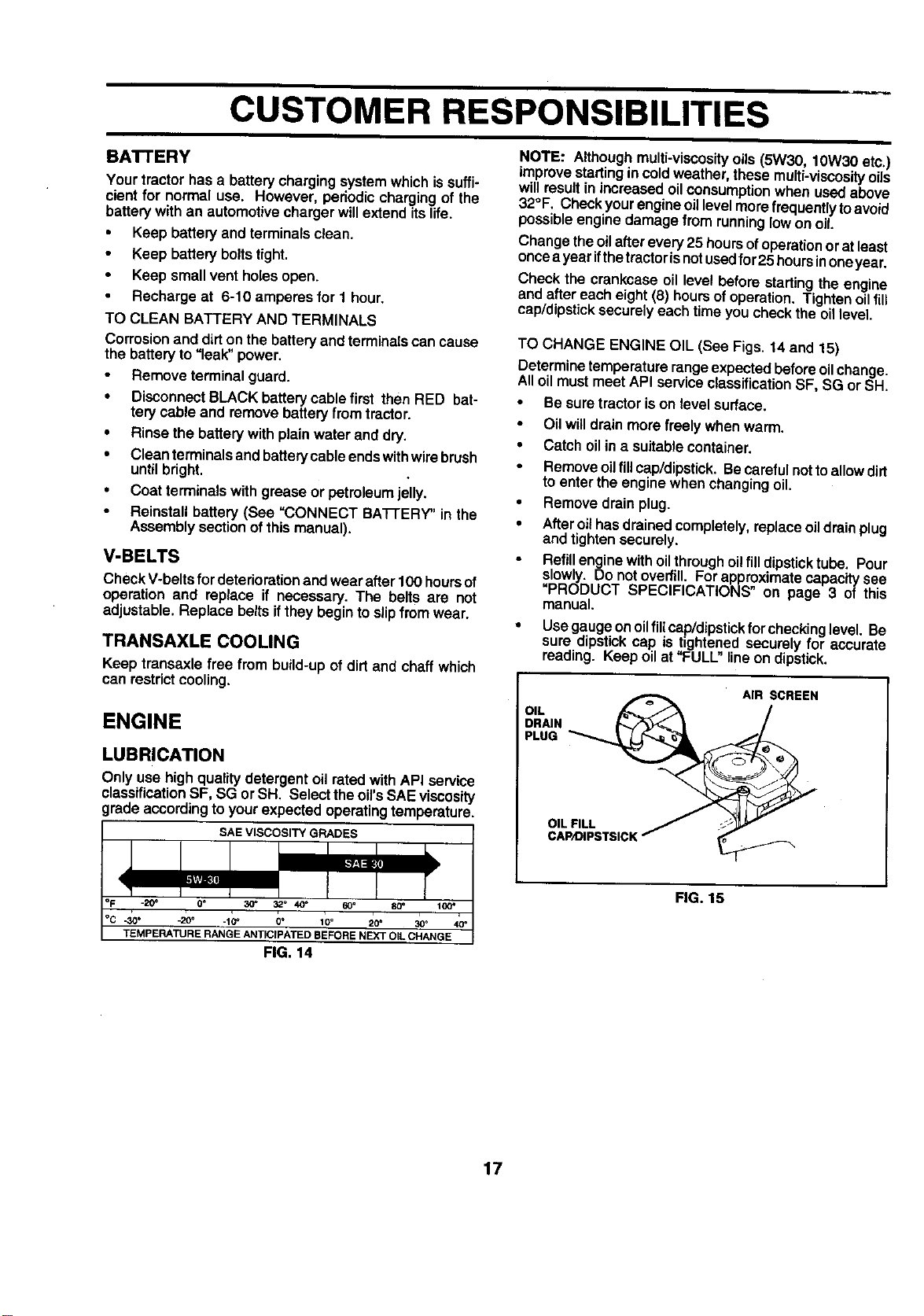
LUBRICATION
Only use high qualitydetergent oilrated withAPI service
classificationSF, SG or SH. Selecttheoil'sSAE viscosity
gradeaccordingtoyourexpected operatingtemperature,
SAE VISCOSITY GRADES
_20_ 0o
.30 • -20o .10 _ 0 ° 10 ° 20 ° 30°
TEMPERATURE RANGE ANTICIPATED BEFORE NEXT OiL CHANGE
FIG, 14
NOTE: Althoughmulti-viscosity oils(5W30, lOW30 etc.)
improve startingin coldweather, thesemulti-viscosityoils
will resultin increased oilconsumptionwhen usedabove
32°F. Checkyour engineoillevelmore frequentlytoavoid
possibleengine damage fromrunninglowon oil.
Changethe oilafterevery25 hoursofoperationorat least
oncea yearifthetractorisnotusedfor25 hoursinoneyear.
Check the crankcase oil level beforestartingthe engine
and after eacheight(6) hoursofoperation. Tightenoilfit_
cap/dipsticksecurely each time you check the oil level.
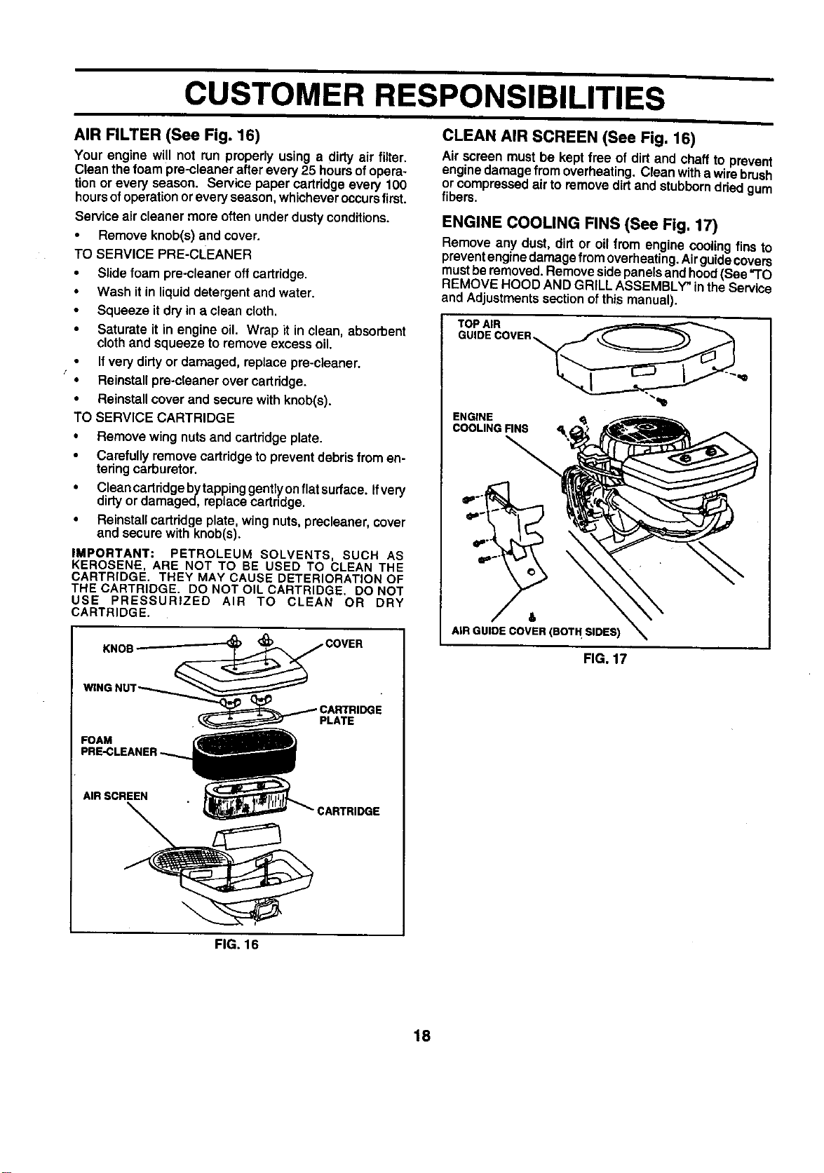
TO CHANGE ENGINE OIL (See Figs. 14 and 15)
Determine temperature range expectedbefore oil change.
All oil must meet API service classificationSF, SG or SH.
Be sure tractor is on level surface.
• Oilwilldrain more freely when warm.
• Catch oilina suitablecontainer.
Remove oilflUcap/dipstick.Be carefulnot toallow dirt
to enter the enginewhen changingoil.
• Remove drain plug.
• Afteroilhasdrainedcompletely,replaceoildrainplug
and tightensecurely.
Refillenginewithoilthroughoilfill dipsticktube. Pour
slowly. Do notoverfill. Forapproximatecapacltysee
=PRODUCT SPECIFICATIONS" on page 3 of this
manual.
• Usegaugeonoilfill cap/dipstickfor checkinglevel. Be
sure dipstickcap is tightened securely for accurate
reading. Keep oil at "FULL"lineon dipstick.
OIL _ AIR SCREEN
°I s,s,cK
FIG. 15
17
CUSTOMER RESPONSIBILITIES
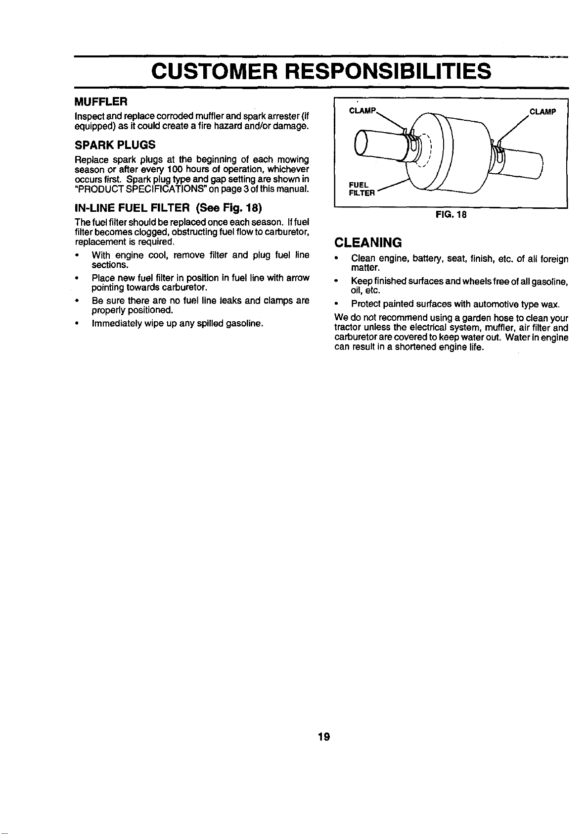
AIR FILTER (See Fig. 16)
Your engine will not run properly using a dirty air filter,
Cleanthefoam pre-cleanerafter every 25 hoursofopera-
tionor every season. Service papercartridgeevery 100
hoursofoperationorevery season,whicheveroccursfirst.
Serviceair cleaner more often underdustyconditions.
• Remove knob(s) and cover.
TO SERVICE PRE-CLEANER
• Slidefoam pre-cleaner offcartridge.
• Wash it inliquiddetergent and water.
• Squeeze itdry in a clean cloth.
• Saturate it in engine oil. Wrap it in clean, absorbent
cloth and squeeze to remove excess oil.
If verydirtyor damaged, replace pre-cleaner.
f
• Reinstallpre-cleanerovercartridge.
• Reinstallcover and secure with knob(s).
TO SERVICE CARTRIDGE
• Remove wing nutsand cartridgeplate.
• Carefullyremovecartridgeto preventdebrisfromen-
teringcarburetor.
• Cleancartridgebytappinggentlyonflatsurtace. Ifvery
dirtyordamaged, replacecartridge.
• Reinstallcartridgeplate,wing nuts,precteaner,cover
and securewith knob(s).
IMPORTANT; PETROLEUM SOLVENTS, SUCH AS
KEROSENE, ARE NOT TO BE USED TO CLEAN THE
CARTRIDGE. THEY MAY CAUSE DETERIORATION OF
THE CARTRIDGE. DO NOT OIL CARTRIDGE. DO NOT
USE PRESSURIZED AIR TO CLEAN OR DRY
CARTRIDGE.
FOAM
PLATE
AIR SCREEN
:ARTRIDGE
CLEAN AIR SCREEN (See Fig. 16)
Air screen mustbe keptfree of dirt and chaff to prevent
enginedamage from overheating.Cleanwithe wirebrush
or compressedair to removedirtand stubbornddedgum
fibers.
ENGINE COOLING FINS (See Fig. 17)
Remove any dust, dirtor oil from engine coolingfins to
preventenginedamagefrom overheating.Airguidecovers
mustbe removed.Removesidepanelsandhood(See "TO
REMOVE HOOD AND GRILL ASSEMBLY" intheService
and Adjustmentssectionofthis manual).
ENGINE <_
COOLING FINS
&
AIR GUIDE COVER (BOT H SIDES)
FIG. 17
FIG. 16
18
CUSTOMER RESPONSIBILITIES
MUFFLER
Inspectend replacecorrodedmufflerandsparkattester(if
equipped)as itcould createa fire hazard and/ordamage.
SPARK PLUGS
Replace spark plugs at the beginning of each mowing
season or after every 100 hoursof operation,whichever
occurs first. Spark plugtype and gapsettingare shownin
"PRODUCT SPECIFICATIONS" onpage 3 ofthismanual.
IN-LINE FUEL FILTER (See Fig. 18)
The fuelfiltershouldbe replacedonce eachseason. Iffuel
filterbecomesclogged,obstructingfuel flowtocarburetor,
replacementis required.
• With engine cool, remove filter and plug fuel line
sections.
• Place new fuel filterin positionin fuel linewitharrow
pointingtowardscarburetor.
• Be sure there are no fuel line leaks and clamps are
properlypositioned.
• Immediatelywipe up any spilledgasoline.
CLAMP CLAMP
FUEL
RLTEI
FIG. 18
CLEANING
• Clean engine, battery, seat, finish, etc. of all foreign
matter.
Keepfinished surfacesand wheelsfree ofallgasoline,
oil, etc.
Protectpainted surfaceswithautomotivetypewax.
We do not recommendusinga garden hose tocleanyour
tractorunlessthe electrical system,muffler,air filter and
carburetorarecoveredtokeepwaterout. Water inengine
can resultin a shortenedengine life.
19
SERVICE AND ADJUSTMENTS
CAUTION: BEFORE PERFORMING ANY SERVICE OR ADJUSTMENTS:
Depress clutch/brake pedal fully and set parking brake.
Place gearshift lever in neutral (N) position.
Place attachment clutch in "DISENGAGED" position.
Turn ignition key "OFF" and remove key.
Make sure the blades and all moving parts have completely stopped.
Disconnect spark plug wire from spark plug and place wire where itcannot come in contact with
plug.
TRACTOR
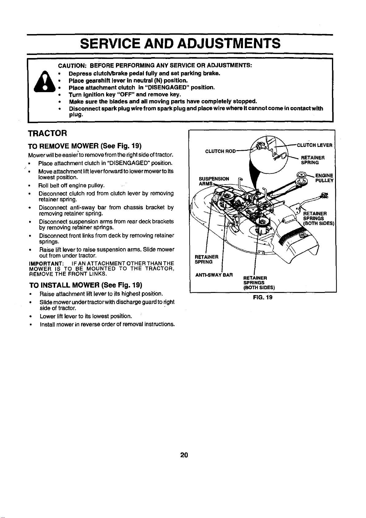
TO REMOVE MOWER (See Fig. 19)
Mowerwillbeeasier'toremovefromtherightsideoftractor,
• Placeattachmentclutchin"DISENGAGED" position.
Moveattachmentliftleverforwardtolowermowertoits
lowestposition.
Rollbelt offengine pulley.
• Disconnectclutch rodfrom clutchlever by removing
retainerspring.
• Disconnect anti-sway bar from chassis bracket by
removingretainerspring.
• Disconnectsuspensionarmsfrom rear deckbrackets
by removingretainersprings.
Disconnectfrontlinksfromdeck byremovingretainer
springs,
• Raise liftleverto raise suspensionarms. Slidemower
outfrom undertractor,
IMPORTANT: IF AN ATTACHMENT OTHER THAN THE
MOWER IS TO BE MOUNTED TO THE TRACTOR,
REMOVE THE FRONT LINKS.
TO INSTALL MOWER (See Fig. 19)
Raise attachment liftleverto itshighestposition.
• Slidemower undertractorwithdischargeguardtoright
side of tractor.
• Lowerliftleverto itslowest position.
• Installmowerin reverseorderof removalinstructions.
RETAINER
SPRING
ANTI-SWAY BAR
RETAINER
SPRINGS
(BOTH SIDES)
FIG. 19
20
SERVICE AND ADJUSTMENTS
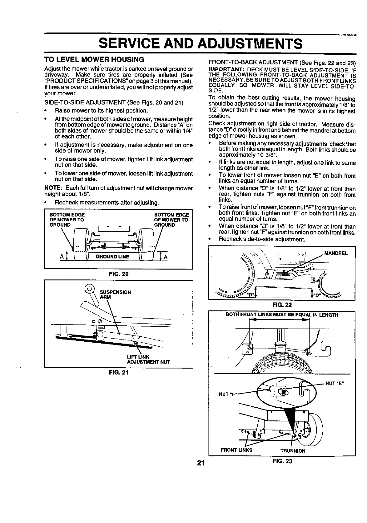
TO LEVEL MOWER HOUSING FRONT-TO-BACK ADJUSTMENT (See Figs. 22 and 23)
Adjustthemower whiletractor isparkedonlevel groundor
driveway. Make sure tires are properly inflated (See
"PRODUCT SPECIFICATIONS" on page 3 ofthis manual).
Iftires are over or underinflated, you will notproperly adjust
your mower.
SIDE-TO-SIDE ADJUSTMENT (See Figs. 20 and 21)
• Raise mower to its highest position.
• Atthemidpointofbothsidesofmower,measureheight
frombottomedgeofmower togreund. Distance=A"on
bothsidesof mowershouldbe thesame orwithin1/4"
of each other.
If adjustment is necessary, make adjustmenton one
side ofmower only.
To raiseone sideof mower,tightenliftlinkadjustment
nuton thatside.
• To lower oneside ofmower, loosen lift link adjustment
nut on that side.
NOTE: Eachfullturnof adjustmentnutwillchangemower
heightabout 1/8".
• Recheck measurementsafter adjusting.
BOTTOM EDGE BOTTOM EDGE
OF MOWER TO OF MOWER TO
GROUND GROUND
IMPORTANT: DECKMUST BELEVELSIDE-TO-SIDE. IF
THE FOLLOWING FRONT-TO-BACK ADJUSTMENT IS
NECESSARY,BESURETOADJUSTBOTHFRONTLINKS
EQUALLY SO MOWER WILL STAY LEVEL SIDE-TO-
SIDE.
To obtain the best cutting results, the mower housing
shouldbe adjustedsothatthefront isapproximately1/8"to
1/2" lowerthan the rear when the mower isin itshighest
position.
Check adjustmenton rightside oftractor. Measure dis-
tance"D"directlyinfront andbehindthe mandrelat bottom
edge of mowerhousingas shown.
• Beforemakinganynecessaryadjustments,checkthat
bothfront linksareequalinlength.Bothlinksshouldbe
approximately10-3/8".
• Iflinksare notequalin length,adjustone linktosame
lengthas otherlink.
• To lowerfront of mower loosen nut "E" on bothfront
linksan equal numberof turns.
• When distance"D" is 1/8" to 1/2" lowerat front than
rear, tighten nuts "P against trunnionon both front
links.
• To raisefront ofmower,loosennut"F"from trunnionon
bothfront links.Tightennut "E" on bothfront linksan
equal numberofturns.
• When distance"D" is 1/8" to 1/2" lowerat front than
rear,tightennut"F"againsttrunniononboth front links.
• Recheckside-to-sideadjustment.
FIG. 20
S SM"ENS'ON
UFT MNK
ADJUSTMENT NUT
FIG. 21
MANDREL
FIG. 22
BOTHFRONTLINKSMUSTBE EQUALIN LENGTH
NUT
NUT "E"
FRONT LINKS TRUNNION
21 FIG. 23
SERVICE AND ADJUSTMENTS
WITH PARKING BRAKE "ENGAGED"
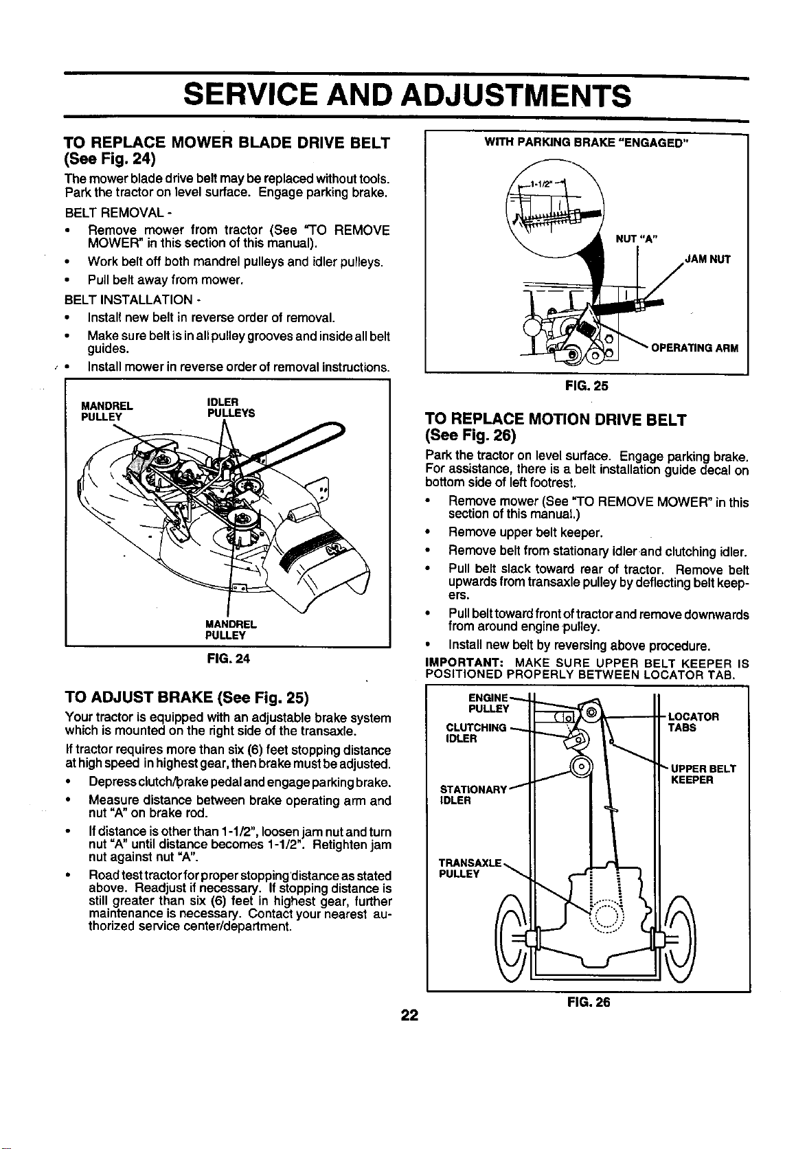
TO REPLACE MOWER BLADE DRIVE BELT
(See Fig. 24)
The mowerbladedrivebelt may bereplacedwithouttools.
Parkthe tractoron level surface. Engage parkingbrake.
BELT REMOVAL -
• Remove mower from tractor (See "TO REMOVE
MOWER" in thissectionofthis manual).
• Workbelt offboth mandrel pulleysand idler pulleys.
• Pullbelt away from mower.
BELT INSTALLATION -
• Installnew belt in reverse order ofremoval.
• Makesurebeltisinall pulleygroovesandinsideallbelt
guides.
Installmowerin reverseorder ofremovalinstructions.
MANDREL IDLER
PULLEY PULLEYS
MANDREL
PULLEY
FIG. 24
TO ADJUST BRAKE (See Fig. 25)
Yourtractoris equippedwith an adjustablebrake system
whichismounted on the rightsideof the transaxle.
Iftractorrequiresmore than six(6) feet stoppingdistance
at highspeed inhighestgear,thenbrakemustbeadjusted.
• Depressciutch/'prakepedaland engageparkingbrake.
• Measure distance between brake operatingarm and
nut "A" on brake rod.
Ifdistanceisotherthan 1-1/2",loosen jam nutand turn
nut =A"untildistance becomes 1-1/2". Retightenjam
nut againstnut "A".
Roadtesttractorfor properstopping'distanceas stated
above, Readjust ifnecessary. Ifstoppingdistanceis
still greater than six (6) feet in highest gear, further
maintenanceis necessary. Contactyournearest au-
thorized servicecenter/department.
NUT"A"
JAM NUT
FIG. 25
TO REPLACE MOTION DRIVE BELT
(See Fig. 26)
Parkthe tractoron level surface. Engage parkingbrake.
Forassistance,there isa belt installationguide decal on
bottomsideof leftfootrest.
• Remove mower(See "TO REMOVE MOWER" in this
sectionof this manual.)
• Remove upperbelt keeper.
Remove beltfrom stationaryidlerand clutchingidler.
• Pull belt slack toward rear of tractor. Remove belt
upwardsfrom transaxlepulleybydeflectingbeltkeep-
ers.
• Pullbelttowardfrontoftractorandremovedownwards
from aroundengine,pulley.
• Installnewbelt byreversingabove procedure.
IMPORTANT: MAKE SURE UPPER BELT KEEPER IS
POSITIONED PROPERLY BETWEEN LOCATORTAB.
ENGINE_
PULLEY
CLUTCHING
IDLER
STATIONARY _
IDLER
TRANSAXLE
PULLEY
-LOCATOR
TABS
UPPER BELT
KEEPER
FIG. 26
22
SERVICE AND ADJUSTMENTS
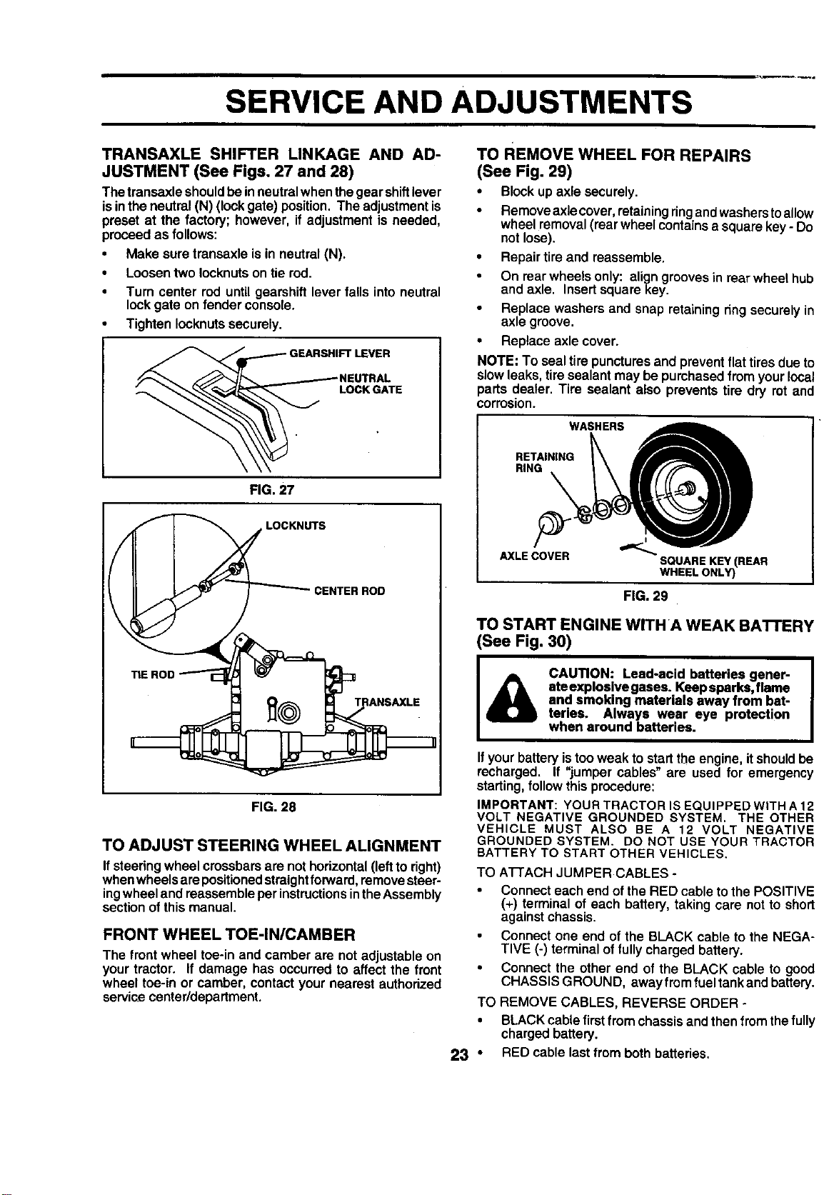
TRANSAXLE SHIFTER LINKAGE AND AD-
JUSTMENT (See Figs. 27 and 28)
Thetransaxleshouldbeinneutralwhenthegear shiftlever
isinthe neutral(N) (lockgate)position.The adjustmentis
preset at the factory; however, ifadjustment is needed,
proceed as follows:
• Make sure transaxleisin neutral (N).
• Loosentwo Iocknutson tie rod.
Turn center rod untilgearshift lever falls intoneutral
lock gate on fender console.
• Tighten Iocknutssecurely.
LOCK GATE
FIG. 27
LOCKNUTS
_ CENTER ROD
TIE ROD -'n
FIG. 28
TO ADJUST STEERING WHEEL ALIGNMENT
Ifsteedng wheel crossbarsare not horizontal (leftto right)
when wheels are positioned straight forward, remove steer-
ing wheel and reassemble per instructions inthe Assembly
section of this manual.
FRONT WHEEL TOE-IN/CAMBER
The front wheel toe-in and camber are not adjustable on
yourtractor. If damage has occurredto affect the front
wheel toe-in or camber, contact your nearest authorized
servicecenter/department.
TO REMOVE WHEEL FOR REPAIRS
(See Fig. 29)
• Blockup axle securely.
Removeaxlecover,retainingringand washerstoallow
wheel removal(rearwheel containsa squarekey- Do
notlose).
• Repairtire and reassemble.
On rearwheels only: aligngroovesin rearwheel hub
and axle. Insertsquarekey.
Replace washers and snap retainingringsecurelyin
axle groove.
• Replace axlecover.
NOTE: To sealtire puncturesand preventflattires due to
slowleaks, tiresealant may be purchasedfrom yourlocal
parts dealer. Tire sealant also prevents tire dry rot and
corrosion.
WASHERS
RETAINING
RING __
AXLE COVER SQUARE KEY (REAR
WHEEL ONLY)
FIG. 29
TO START ENGINE WITHA WEAK BA'n'ERY
(See Fig. 30)
CAUTION: Lead-acid batteries gener-
ateexplosive gases. Keepsparks,flame
and smoking materials away from bat-
teries. Always wear eye protection
when around batteries.
If your battery istoo weak to start the engine, it should be
recharged. If "jumper cables" are used for emergency
starting, follow this procedure:
IMPORTANT: YOUR TRACTOR IS EQUIPPED WITH A 12
VOLT NEGATIVE GROUNDED SYSTEM. THE OTHER
VEHICLE MUST ALSO BE A 12 VOLT NEGATIVE
GROUNDED SYSTEM. DO NOT USE YOUR TRACTOR
BATTERY TO START OTHER VEHICLES.
TO A'I-FACH JUMPER CABLES -
• Connect each end of the RED cable to the POSITIVE
(+) terminal of each battery, taking care not to short
against chassis.
Connect one end of the BLACK cable to the NEGA-
TIVE (-) terminal of fully charged battery.
• Connect the other end of the BLACK cable to good
CHASSIS GROUND, away from fuel tank and battery.
TO REMOVE CABLES, REVERSE ORDER -
• BLACK cable first from chassis and then from the fully
chargedbattery.
23 " RED cable lastfrom both batteries.
SERVICE AND ADJUSTMENTS
ENGINE
"POSITIVE" (+) "NEGATIVE" (-)
L.H. PANEL
BOLT
FIG. 30
TO REPLACE HEADLIGHT BULB
• Raise hood.
• Pullbulbholderout of the hole inthe backsideof the
grill.
Replace bulbin holderand pushbulb holdersecurely
backintothe holein the backsideof the grill.
• Closehood.
INTERLOCKS AND RELAYS
Looseor damaged wiringmay cause yourtractorto run
poorly,stoprunning,or preventitfrom starting.
• Check wiring. See electrical wiring diagram in the
Repair Partssectionof this manual.
TO REPLACE FUSE
Replacewith 30 amp automotive-typeplug-infuse. The
fuse holderis locatedbehindthe dash.
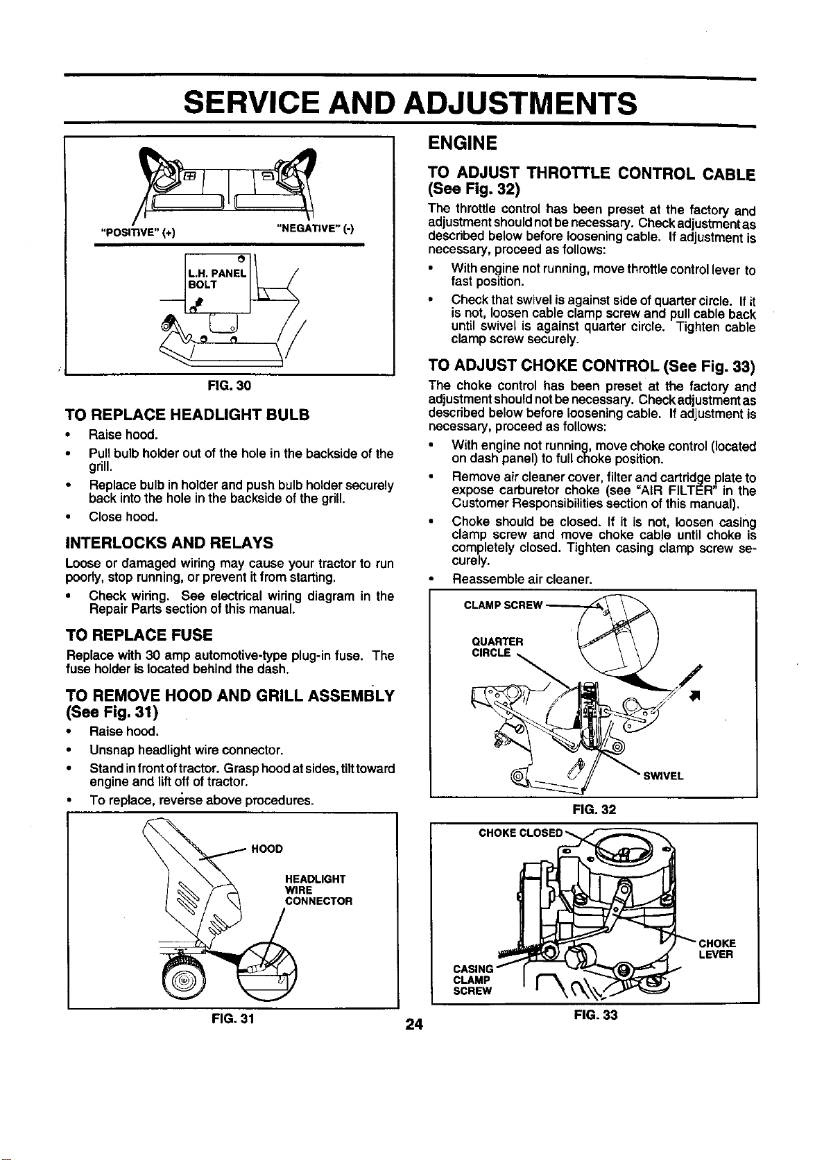
TO REMOVE HOOD AND GRILL ASSEMBLY
(See Fig. 31)
• Raise hood.
Unsnap headlightwire connector.
Standinfrontoftractor. Grasphoodat sides,tilttoward
engine and liftoffoftractor.
To replace, reverse above procedures.
HOODHEADLIGH T
ECTOR
FIG. 31
24
TO ADJUST THROTTLE CONTROL CABLE
(See Fig. 32)
The throttle control has been preset at the factory and
adjustmentshouldnotbe necessary.Checkadjustmentas
describedbelowbeforelooseningcable. If adjustmentis
necessary,proceedas follows:
• Withenginenot running,movethrottlecontrollever to
fast position.
• Check thatswivelisagainstsideofquarter circle. Ifit
is not,loosencable clamp screw and pullcable back
until swivel is against quarter circle. Tighten cable
clamp screwsecurely.
TO ADJUST CHOKE CONTROL (See Fig. 33)
The choke control has been preset at the factory and
adjustmentshouldnotbe necessary.Checkadjustmentas
describedbelowbefore loosening cable. Ifadjustmentis
necessary,proceedas follows:
• With engine notrunning,movechoke control(located
on dash panel)to full choke position.
Remove air cleanercover,filter and cartridgeplateto
expose carburetor choke (see "AIR FILTER" in the
CustomerResponsibilitiessectionof thismanual).
• Choke should be closed. If it is not, loosen casing
clamp screw and move choke cable until choke is
completely closed. Tighten casing clamp screw se-
curely.
Reassembleair cleaner.
QUARTER ' (
CIRCLE
SWIVEL
FIG. 32
CLAMP
SCREW
LEVER
FIG. 33
SERVICE AND ADJUSTMENTS
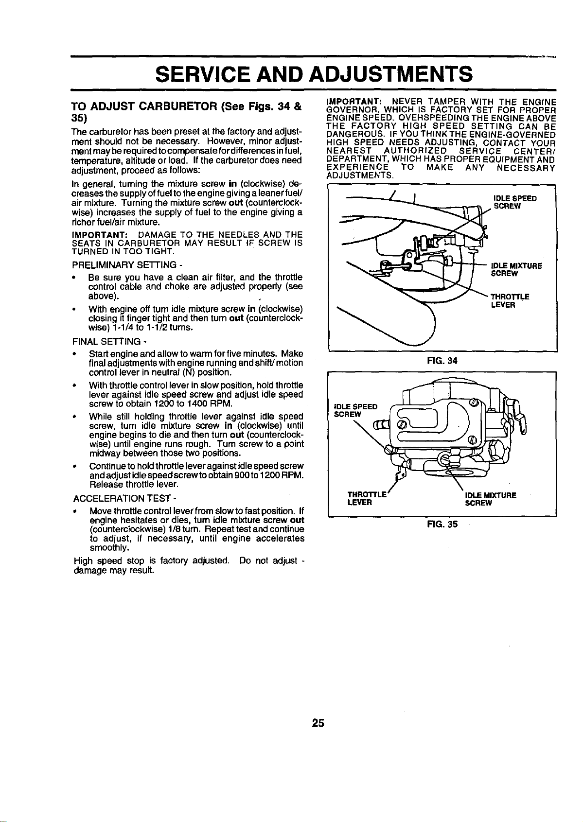
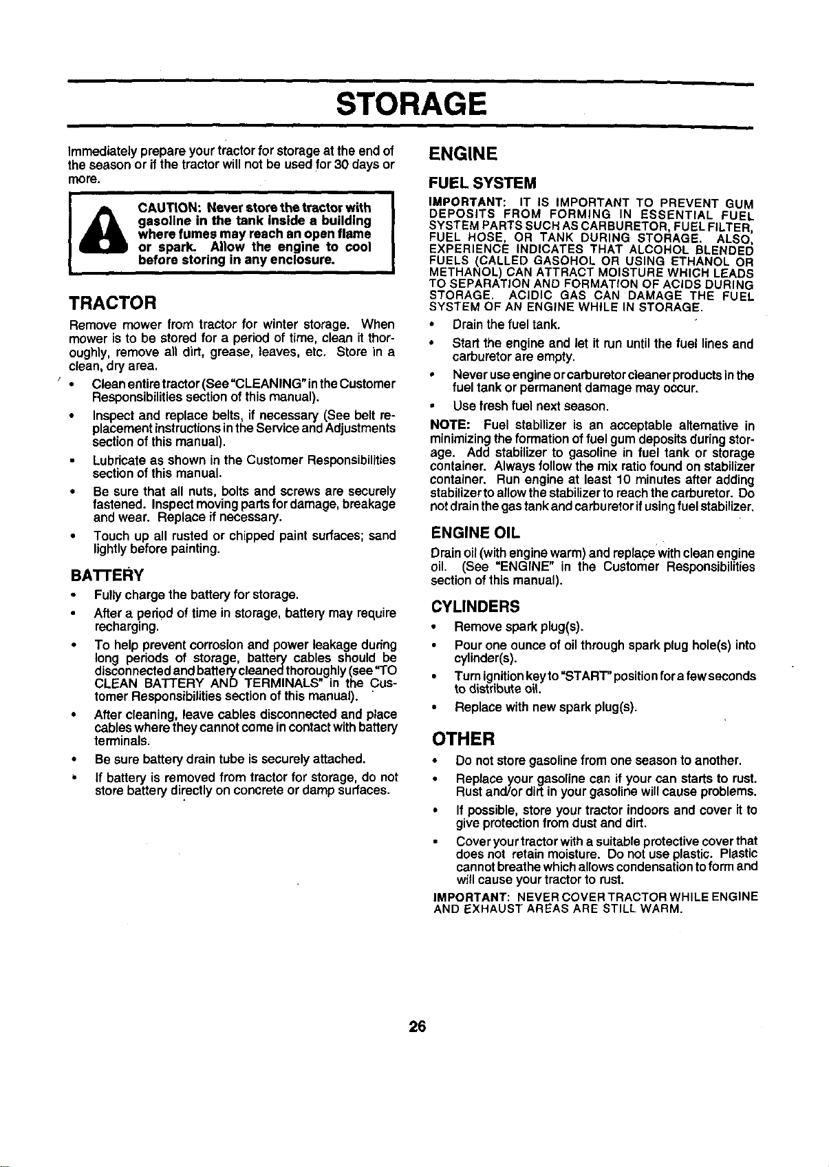
TO ADJUST CARBURETOR (See Figs. 34 &
35)
The carburetorhas been preset at thefactory and adjust-
ment should not be necessary. However, minor adjust-
ment may be requiredtocompensatefor differencesinfuel,
temperature,altitudeor load. Ifthecarburetordoesneed
adjustment,proceed as follows:
In general, turning the mixture screw in (clockwise)de-
creasesthesupplyoffuel totheenginegivinga leanerfuel/
air mixture. Turningthe mixturescrewout (counterclock-
wise) increasesthe supply offuel to the engine givinga
richerfuel/air mixture.
IMPORTANT: DAMAGE TO THE NEEDLES AND THE
SEATS IN CARBURETOR MAY RESULT IF SCREW IS
TURNED IN TOO TIGHT.
PRELIMINARY SETI'ING -
• Be sure you have a clean air filter, and the throttle
control cable and choke are adjusted properly (see
above).
Withengine offturn idle mixture screwin (clockwise)
closingitfinger tightand then turnout (counterclock-
wise) 1-1/4 to 1-1/2 turns.
FINAL SETTING -
• Startengine andallowto warmforfive minutes. Make
final ad ustmentswithengine runningandshift/motion
controllever in neutral(N) positon.
• Withthrottlecontrol lever inslow position,holdthrottle
lever against idle speed screw and adjustidlespeed
screwto obtain 1200 to 1400 RPM.
While still holding throttle lever against idle speed
screw, turn idle mixture screw in (clockwise) until
engine begins to die and then turn out (counterclock-
wise) until engine runs rough. Turn screw to a point
midway between those two positions.
Continue to holdthrottle lever against idle speedscrew
and ad ust idlespeed screwto obtain 900to 1200 RPM.
Re ease thrott e ever.
ACCELERATION TEST -
• Move throttlecontrol leverfrom slowtofast position.If
engine hesitatesor dies, turn idle mixturescrew out
(counterclockwise)1/8turn. Repeat testandcontinue
to adjust, if necessary, until engine accelerates
smoothly.
High speed stop is factory adjusted. Do not adjust -
damage may result.
IMPORTANT= NEVER TAMPER WITH THE ENGINE
GOVERNOR, WHICH IS FACTORY SET FOR PROPER
ENGINE SPEED. OVERSPEEDING THE ENGINE ABOVE
THE FACTORY HIGH SPEED SETTING CAN BE
DANGEROUS. IF YOU THINKTHE ENGINE-GOVERNED
HIGH SPEED NEEDS ADJUSTING, CONTACT YOUR
NEAREST AUTHORIZED SERVICE CENTER/
DEPARTMENT, WHICH HAS PROPER EQUIPMENT AND
EXPERIENCE TO MAKE ANY NECESSARY
ADJUSTMENTS,
IDLE SPEED
SCREW
IDLE MIXTURE
SCREW
LEVER
FIG. 34
LEVER SCREW
FIG. 35
25
STORAGE
ENGINE
Immediatelyprepare yourtractorfor storageat the end of
theseason or ifthe tractorwillnot be usedfor 30 days or
more.
CAUTION: Never store the tractor with
gasoline in the tank inside a building
where fumes may reach an open flame
or spark Allow the engine to cool
before storing in any enclosure.
TRACTOR
Remove mower from tractor for winter storage. When
mower is to be stored for a period of time, clean it thor-
oughly, remove an dirt, grease, leaves, etc, Store in a
clean, dry area.
,.. CleanenUretractor(See=CLEANING"intheCustomer
Responsibilities sectionof this manual).
• Inspect and replace belts, if necessary (See belt re-
placement instructionsin the Service and Adjustments
section of this manual).
Lubricate as shown in the Customer Responsibilities
sectionof this manual.
• Be sure that all nuts, bolts and screws are securely
fastened. Inspectmovingpartsfordamage,breakage
and wear. Replace ifnecessary.
• Touch up all rustedor chipped paintsurfaces;sand
lightlybefore painting.
BA'n'ERY
Fully charge the battery for storage.
After a pedod of time in storage, battery may require
recharging.
To help prevent corrosion and power leakage dudng
long periods of storage, battery cables should be
disconnected andbatterycleaned thoroughly (see"TO
CLEAN BATI'ERY AND TERMINALS" in the Cus-
tomer Responsibilities section of this manual). "
After cleaning, leave cables disconnected and place
cableswhere they cannot come in contactwith battery
terminals.
• Besure batterydrain tube issecurelyattached.
• If battery is removed from tractorfor storage,do not
storebattery directlyon concreteor damp surfaces.
FUEL SYSTEM
IMPORTANT: IT IS IMPORTANT TO PREVENT GUM
DEPOSITS FROM FORMING IN ESSENTIAL FUEL
SYSTEM PARTS SUCH AS CARBURETOR, FUEL FILTER,
FUEL HOSE, OR TANK DURING STORAGE. ALSO,
EXPERIENCE INDICATES THAT ALCOHOL BLENDED
FUELS (CALLED GASOHOL OR USING ETHANOL OR
METHANOL) CAN ATTRACT MOISTURE WHICH LEADS
TO SEPARATION AND FORMATION OF ACIDS DURING
STORAGE. ACIDIC GAS CAN DAMAGE THE FUEL
SYSTEM OF AN ENGINE WHILE IN STORAGE.
• Drainthe fuel tank.
• Start the engine and let it run untilthe fuel lines and
carburetor are empty.
• Never useengine orcarburetorcleaner products inthe
fuel tank or permanent damage may occur.
• Use fresh fuel nextseason.
NOTE: Fuel stabilizer is an acceptable alternative in
minimizingthe formation offuel gum depositsduringstor-
age. Add stabilizer to gasoline in fuel tank or storage
container. Always follow the mix ratiofound on stabilizer
container. Run engine at least 10 minutesafter adding
stabilizertoaflowthestabilizertoreachthecarburetor.Do
notdrainthegastankandcarburetorifusingfuel stabilizer.
ENGINE OIL
Drainoil (with enginewarm)and replacewithcleanengine
oil. (See =ENGINE" in the Customer Responsibilities
sectionofthismanual).
CYLINDERS
• Remove sparkplug(s).
Pourone ounceof oilthroughspark plug hole(s)into
cylinder(s).
• Turnignitionkeyto"START" positionfora few seconds
to distdbuteoIL
• Replace with new spark plug(s).
OTHER
• Do not storegasolinefrom one season toanother.
• Replace your gasolinecan ifyour can startsto rust.
Rustand/ordirtin yourgasolinewillcause problems.
• If possible,store your tractorindoorsand cover it to
give protectionfrom dust and dirt.
Coveryourtractorwitha suitableprotectivecoverthat
does not retainmoisture. Do notuseplastic. Plastic
cannotbreathewhichallowscondensationtoform and
willcauseyourtractorto rust.
IMPORTANT: NEVER COVER TRACTOR WHILE ENGINE
AND EXHAUST AREAS ARE STILL WARM.
26
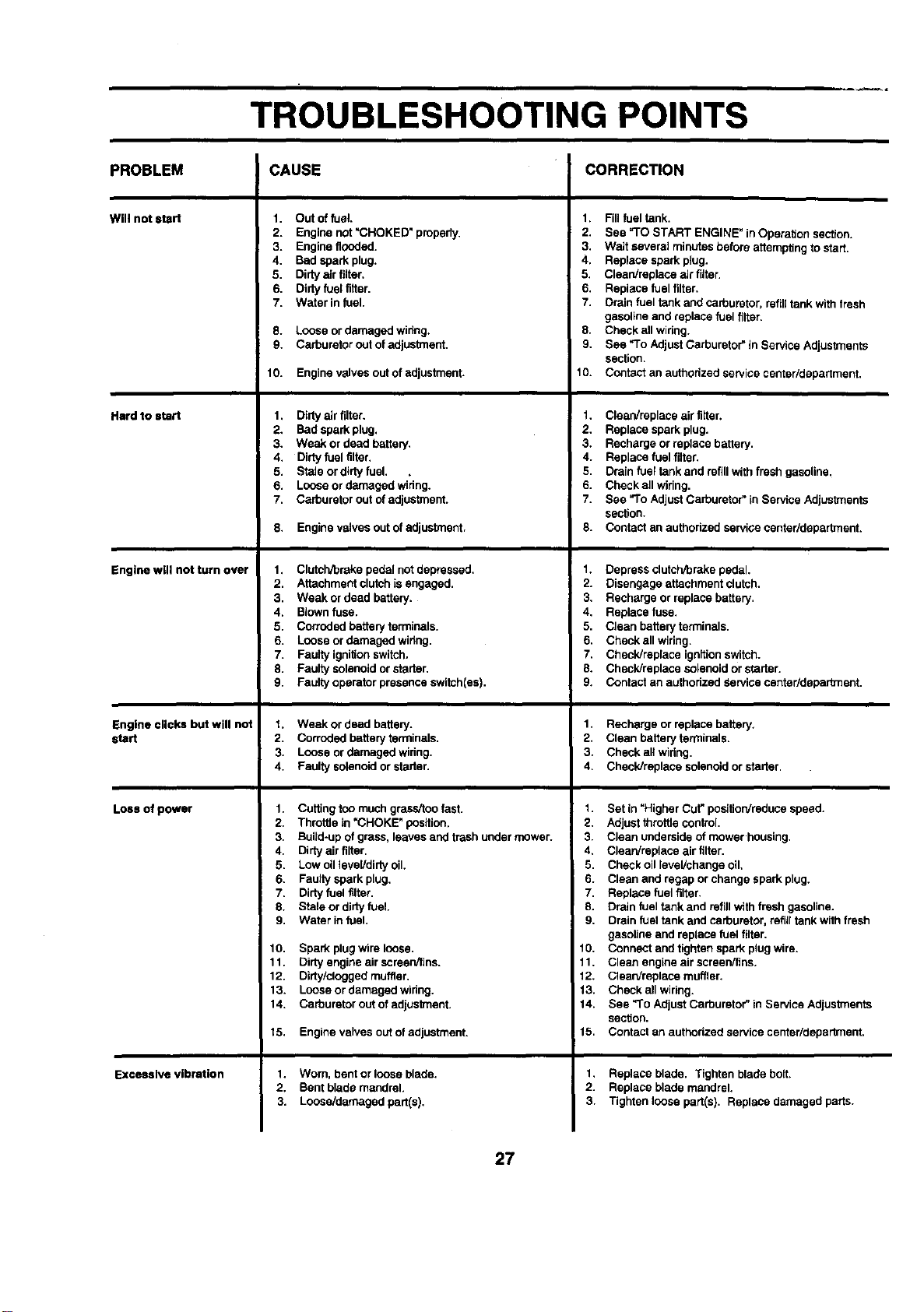
TROUBLESHOOTING POINTS
CAUSE CORRECTIONPROBLEM
Will notstart
Hard to start
Engine wig not turn over
Engine clicks but will not
start
Loss of power
Excessive vibration
1. Out offuel.
2. Engine not "CHOKED" properly.
3. Engine flooded.
4. Bad spark plug.
5. Dirtya_rfilter.
6. Dirtyfuel fitter.
7. Water in fuel.
8. Loose or damaged wiring.
9. Carburetor outof adjuslment.
10. Engine valves outof adjustment.
1. Dirty air filter.
2. Bad spark plug.
3. Weak or dead battery.
4. Dirtyfuel tilter.
5. Stale or dirty fuel. .
6. Loose or damaged wiring.
7. Carburetor out of adjustment.
8. Engine valvesout of adjustment.
1. Clutch/breke pedal notdepressed,
2. Attachment clutchis engaged.
3, Weak or dead battery,
4, Blownfuse.
5. Corroded battery terminals.
6. Loose or damaged wiring,
7. Faulty ignitionswitch.
8. Faulty solenoid or stader,
9. Faulty operator presence switch(es),
t. Weak or dead battery.
2. Corroded battery terminals.
3. Loose ordamaged wiring.
4. Faulty solenoidor starter.
1. Cuffing too much grass/too fast.
2. Throttle in =CHOKE"position.
3. Build-up of grass, leaves and trash under mower.
4. Dirty air tilter.
5. Low oil level/dirtyoil.
6. Faulty spark plug.
7. Dirtyfuel filter.
8. Stale or dirty fuel.
9. Water in fuel.
10. Spark plug wire loose.
11. Dirtyengine airscreen/fins.
12. Dirty/clogged muffler.
13. Loose or damaged wiring.
14. Carburetor out of adjustment.
15. Engine valves outof adjustment.
1. Worn. bent or loose blade.
2. Bent blade mandrel.
3. Loose/damaged part(s).
1. Fill fuel tank.
2. See =TOSTART ENGINE" in Operation section.
3. Wait several minutesbefore attemptingtostart.
4. Replace spark plug.
5. Clean/replace air fitter.
6. Replace fuel filter.
7. Drain fuel tank and carburetor, refilltank with fresh
gasoline and replace fuel tilter=
8. Check all widng.
9. See *To Adjust Carburetor"in Service Adjustments
section.
10. Contact an authorized service center/department.
1. Clean/replece air filter.
2. ReplaCespark plug.
3. Recharge or replace battery.
4. Replace fuel filter.
5. Drainfuel tank and refillwithfresh gasoline.
6. Check all wiring.
7. See "ToAdjustCarburetor" in Service Adjustments
section.
8. Contact an authorized service centarldepartment.
1. Depress clutchrbrakepedal.
2. Disengage attachment clutch.
3, Recharge or replace battery,
4, Replace fuse,
5, Clean batteryterminals.
E, Check all wiring.
7, Check/replace ignftionswitch.
8. Check/replace solenoidor starter,
9. Contact an authorized Service center/department,
1. Recharge or replace battery.
2. Clean battery terminals.
3. Check all widng.
4. Check/replace solenoidorstarter.
1. Set in =Higher Cut"posttionireducespeed.
2. Adjustthrottle control.
3. Clean underside of mowerhousing.
4. Clean/replace air filter.
5. Check oil level/change oil.
6. Clean and regap orchange spark plug.
7. Replace fuel filter.
8. Drain fuel tank and refillwith fresh gasoline.
9. Drain fuel tank and carburetor,refilltank with fresh
gasoline and replace fuel filter.
10. Connect and tighten spark plug wire.
11. Clean engine airscreen/tins.
12. Clean/replace muffler.
13. Check all wiring.
14. See "ToAdjustCarburetor" in Service Adjustments
section.
15. Contact an authorized service centar/department.
1, Replace blade. Tighten blade bolt.
2. Replace blade mandrel,
3. Tighten loose part(s). Replace damaged parts.
27
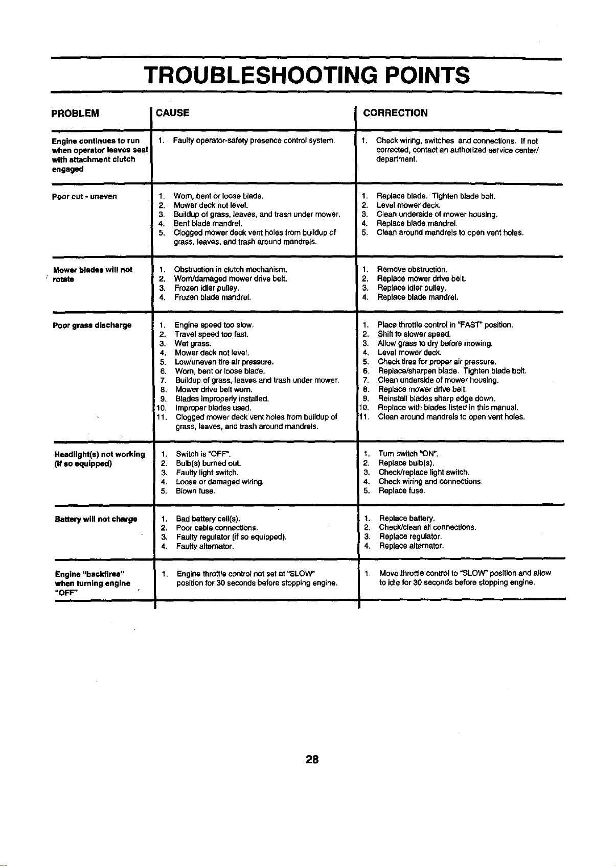
TROUBLESHOOTING POINTS
PROBLEM CAUSE CORRECTION
Engine continues to run
when operator leaves seat
with attachment clutch
engaged
Pooreut-uneven
Mower blades will not
" rotJte
Poor grass discharge
HeedUght(s) not working
(if so equipped)
Battery will not charge
Engine "backfires"
when turning engine .
"OFF"
1. Faultyoperator-safety presence controlsystem.
1. Worn, bent or loose blade.
2. Mower deck not level.
3. Buildup of grass,leaves, and trashunder mower.
4. Bent blade mandrel.
5. Clogged mower deck vent holes from buildup of
grass, leaves, and trash around mandrels.
1. Obstruction in clutch mechanism.
2. WorrVdamagedmower drivebelt.
3. Frozen idlerpulley.
4. Frozen blade mandrel.
1. Engine speed too slow.
2. Travel speed toofast.
3. Wet grass.
4. Mower deck not level.
5. Low/uneven tire air pressure.
6. Worn, bent or loose blade.
7. Buildupof grass,leaves and trash under mower.
8. Mower ddve belt worn.
9. Blades improperly installed.
10. Improper blades used.
11. Clogged mower deck vent holes from buildupof
grass, leaves, and trash aroundmandrels.
1. Switch is "OFF".
2. Bulb(s) burnedout.
3. Faulty light switch.
4. Loose or damaged widng.
5. Blownfuse.
1. Bad battery cell(s).
2. Pcor cable connections.
3. Faulty regulator (ifso equipped).
4. Faulty altemator.
1. Engine throttlecootro_notset at "SLOW"
positionfor 30 seconds before stoppingengine.
t, Check wiring, switches and connections. If not
corrected,contactan authorized service center/
department.
1. Replace blade. Tighten blade bolt.
2. Level mower deck.
3. Clean underside ofmower housing.
4. Replace blade mandrel.
5. Clean around mandrels to open vent holes.
1. Remove obstruction.
2. Replace mower drive belt.
3. Replece idlerpulley.
4. Replace blade mandrel.
1. Place throttlecontrolin _FAS'F position.
2. Shift toslower speed.
3. Allow grass todry before mowing.
4. Level mower deck.
5. Check tiresfor proper air pressure.
6. Replece/sharpen blade. Tighten blade bolt.
7. Clean underside ofmower housing.
8. Replace mower drivebelt•
9. Reinstallblades sharp edge down.
10. Replace with blades listed in this manual.
11. Clean aroundmandrels to open vent holes.
t. Tum switch"ON".
2. Replace bulb(s).
3. Check/replace lightswitch.
4. Check widng andconnections.
5. Replece fuse.
1. Replace battery.
2. Check/clean all connections.
! 43. Replace regulator.
• Replace alternator.
"l. Move.throttlecontrol to"SLOW" positionand allow
to idle for30 seconds before stopping engine.
28
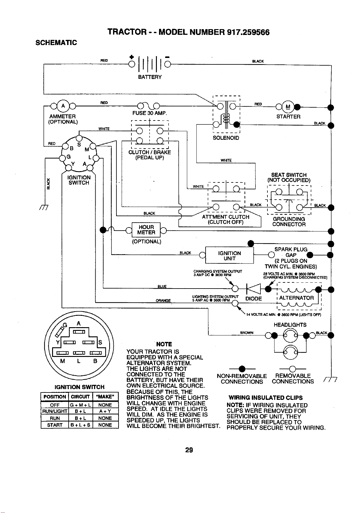
TRACTOR - - MODEL NUMBER 917.259566
SCHEMATIC
RED
BATTERY
BLACK
/7
RED
) WHITE
IG L(
IGNITION
SWITCH
FUSE 30 AMP.
r ------I
I I
I
J (_LUTCH / BRAKJE
(PEDAL UP)
N.._K
HOURMETER ]_
(OPTIONAL)
i
[
I RED
STARTER
BLACK
L WHITE
SEAT SWITCH
(NOT OCCUPIED)
WHITE I........ I t .... ----.--1
I I
I I I _ l-
....GROUND,NG
(CLUTCH OFF) I
CONNECTOR
BLACK _ IGNITIONUNIT
IGNITION SWITCH
PosmoN CIRCUIT "MAKE"
OFF G + M + L NONE
RUN/LIGHT B + L A + Y
RUN B + L NONE
START B + L + S NONE
J__ SPARK PLUG
GAP
(2 PLUGS ON
TWIN CYL, ENGINES)
CHARGJNG SYSTEM OUTPUT
3 AMP DC @ 36_ RPM '28 VOLTS AC MIN. @ 3600 RPM
(CHARGINGSYSTEMDISCONNECllED
BLUE I_
LIGHTING SYSTEM _ I l
ORANGE 5 AMP AC, 36_0 _ 'I--_ /
L sRow.
NOTE
YOUR TRACTOR IS
EQUIPPED WITH A SPECIAL
ALTERNATOR SYSTEM.
THE LIGHTS ARE NOT
CONNECTED TO THE
BATFERY, BUT HAVE THEIR
OWN ELECTRICAL SOURCE.
BECAUSE OF THIS, THE
BRIGHTNESS OF THE LIGHTS
WILL CHANGE WITH ENGINE
SPEED. AT IDLE THE LIGHTS
WILL DIM. AS THE ENGINE IS
SPEEDED UP, THE LIGHTS
WILL BECOME THEIR BRIGHTEST.
• ©
NON-REMOVABLE REMOVABLE
CONNECTIONS CONNECTIONS
WIRING INSULATED CLIPS
NOTE: IF WIRING INSULATED
CLIPS WERE REMOVED FOR
SERVICING OF UNIT, THEY
SHOULD BE REPLACED TO
PROPERLY SECURE YOUR WIRING.
29
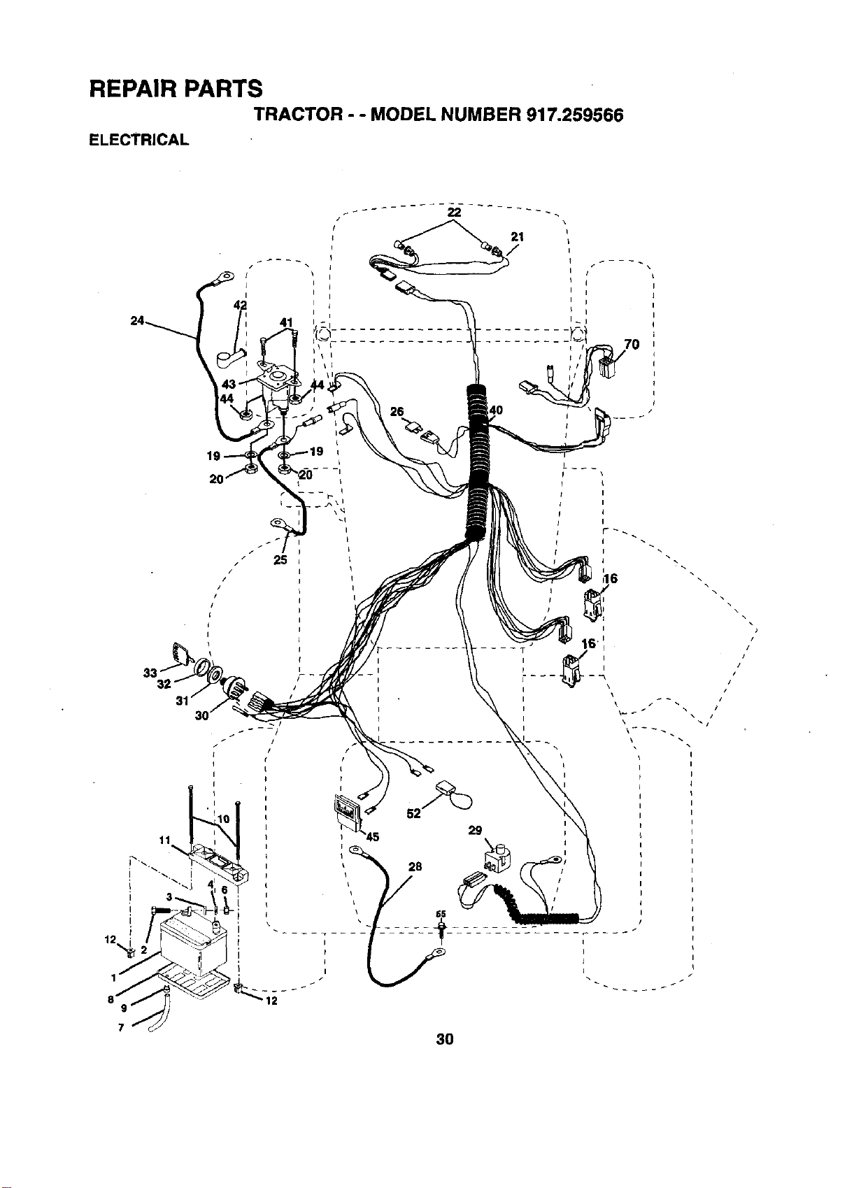
REPAIR PARTS
TRACTOR - - MODEL NUMBER 917.259566
ELECTRICAL
/
I
I
42
41
25
/
p16
I \\
3O
,,,/
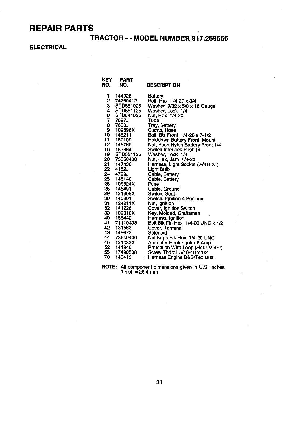
REPAIR PARTS
TRACTOR - - MODEL NUMBER 917.259565
ELECTRICAL
KEY PART
NO. NO. DESCRIPTION
1 144926 Battery
2 74760412 Bolt, Hex 1/4-20 x 3/4
3 STD551025 Washer 9/32 x 5/8 x 16 Gauge
4 STD551125 Washer, Lock 1/4
6 STD541025 Nut, Hex 1/4-20
7 7697J Tube
8 7603J Tray, Battery
9 109596X Clamp, Hose
10 145211 Bolt, BtrFmnt 1/4-20x7-1/2
11 150109 HolddownBattery Front Mount
12 145769 Nut, Push NylonBattery Front 114
16 153664 Switch InterlockPush-In
19 STD551125 Washer, Lock 1/4
20 73350400 Nut, Hex, Jam 1/4-20
21 147430 Hamess, LightSocket (w/4152J)
22 4152J LightBulb
24 4799J Cable, Battery
25 146148 Cable, Battery
26 108824X Fuse
28 145491 Cable, Ground
29 121305X Switch,Seat
30 140301 Switch,Ignition4 Position
31 124211X Nut, Ignition
32 141226 Cover, IgnitionSwitch
33 109310X Key, Molded,Craftsman
40 156442 Harness, Ignition
41 71110408 BoltBIk FinHex 1/4-20 UNC x 1/2
42 131563 Cover, Terminal
43 145673 Solenoid
44 73640400 Nut Keps BIk Hex 1/4-20 UNC
46 121433X Ammeter Rectangular6 Amp
52 141940 ProtectionWire Loop(Hour Meter)
55 17490508 ScrewThdrel 5/16-18 x 1/2
70 140413 . Harness EngineB&S/Tec Dual
NOTE: All componentdimensionsgiven in U.S. inches
1 inch= 25.4 mm
31
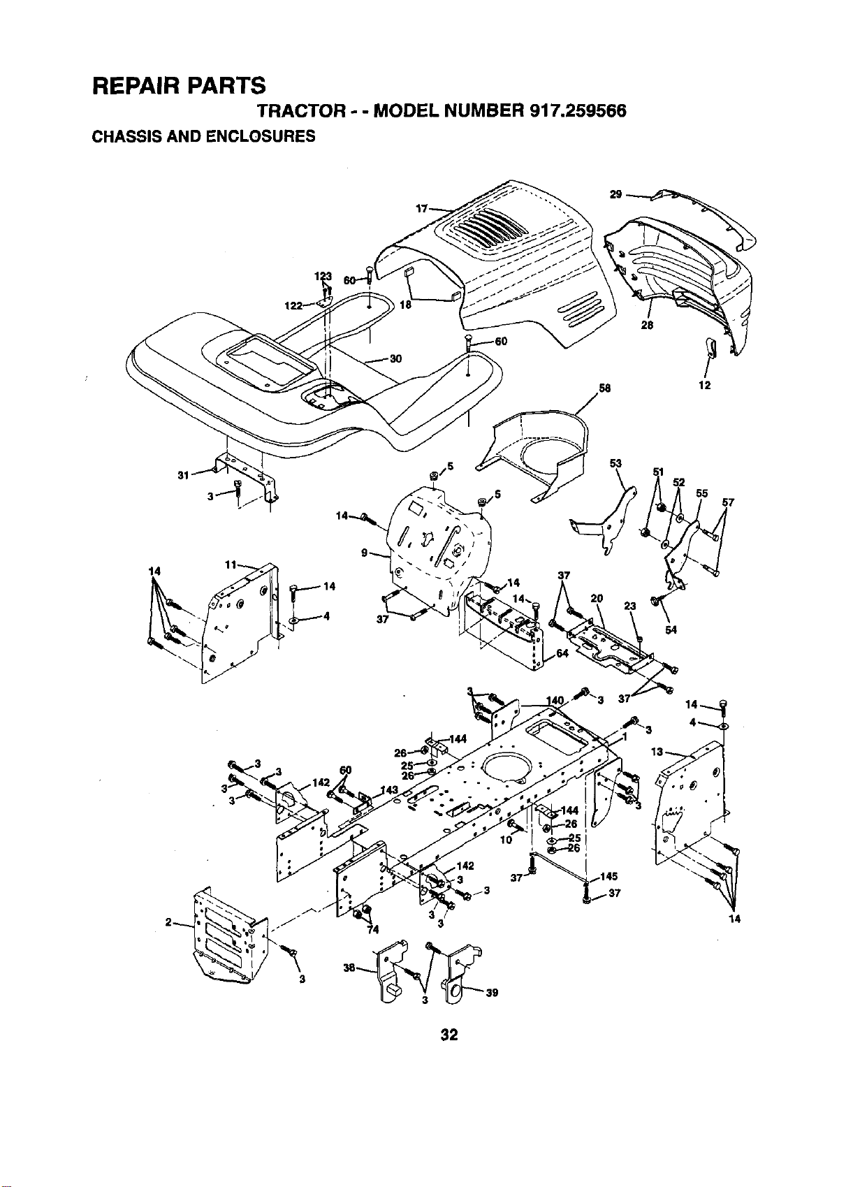
REPAIR PARTS
TRACTOR - - MODEL NUMBER 917,259566
CHASSIS AND ENCLOSURES
28
12
31
37
53
55
7
3
54
32
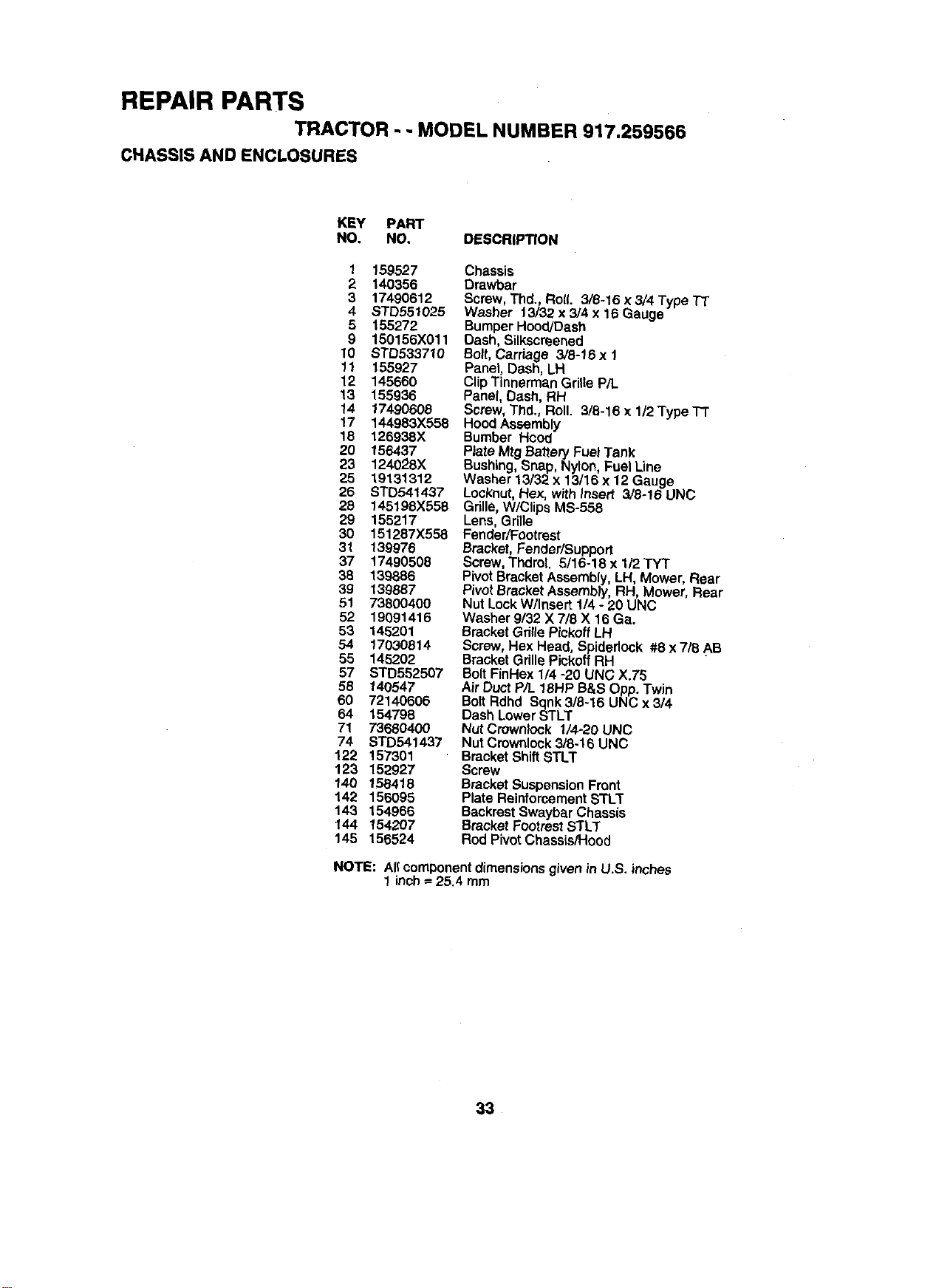
REPAIR PARTS
TRACTOR - - MODEL NUMBER 917.259566
CHASSIS AND ENCLOSURES
KEY PART
NO. NO, DESCRIPTION
1 159527
2 140356
3 17490612
4 STD551025
5 155272
9 150156X011
10 STD533710
11 155927
12 145660
13 155936
14 17490608
17 144983X558
18 126938X
20 156437
23 124028X
25 19131312
26 STD541437
28 145198X558
29 155217
30 151287X558
31 139976
37 17490506
38 139886
39 t 39887
51 73800400
52 19091416
53 146201
54 17030814
55 145202
57 STD552507
58 140547
60 72140605
64 154798
71 73680400
74 STD541437
122 157301
123 152927
140 158418
142 156095
143 154966
144 154207
145 156524
Chassis
Drawbar
Screw, Thd., Ro((. 3/8-16 x 3/4 Type TT
Washer 13/32 x 3/4 x 16 Gauge
BumperHood/Dash
Dash, Silkscreened
Bolt,Carriage 3/8-16 x 1
Panel, Dash, LH
ClipTinnerman Grille P/L
Panel, Dash, RH
Screw, Thd., Roll. 3/8-16 x 1/2 Type-IT
Hood Assembly
Bumber Hood
Plate Mtg Battery Fuel Tank
Bushing, Snap, Nylon, Fuel Line
Washer 13132x 13/16 x 12 Gauge
Locknut, Hex, with insert 3/6-16 UNC
Gdlle, W/Clips MS-558
Lens, Grille
Fender/Footrest
Bracket, Fender/Support
Screw, ThdroL 5/16-18 x 1/2 "rYT
Pivot Bracket Assembly, LH, Mower, Rear
Pivot BracketAssembly, RH, Mower, Rear
Nut Lock W/Insert 1/4 - 20 UNC
Washer 9/32 X 7/8 X 16 Ga.
Bracket Gdlle Pickoff LH
Screw, Hex Head, Spideriock #8 x 7/6 AB
Bracket Grille Piekoff RH
Bolt FinHex 1/4 -20 UNC X.75
Air Duct P/L 16HP B&S Opp. Twin
Bolt Rdhd Sqnk3/8-16 UNC x 3/4
Dash LowerSTLT
Nut Crownk)ck 1/4-20 UNC
Nut Cmwnlock3/8o16UNC
BracketShift STLT
Screw
BracketSuspensionFront
PlateReinforcementSTLT
BackrestSwaybarChassis
BracketFootrestSTLT
RodPivotChassis/Hood
NOTE: AI(componentdimensions givenin U.S. inches
1 inch_ 25.4 mm
33
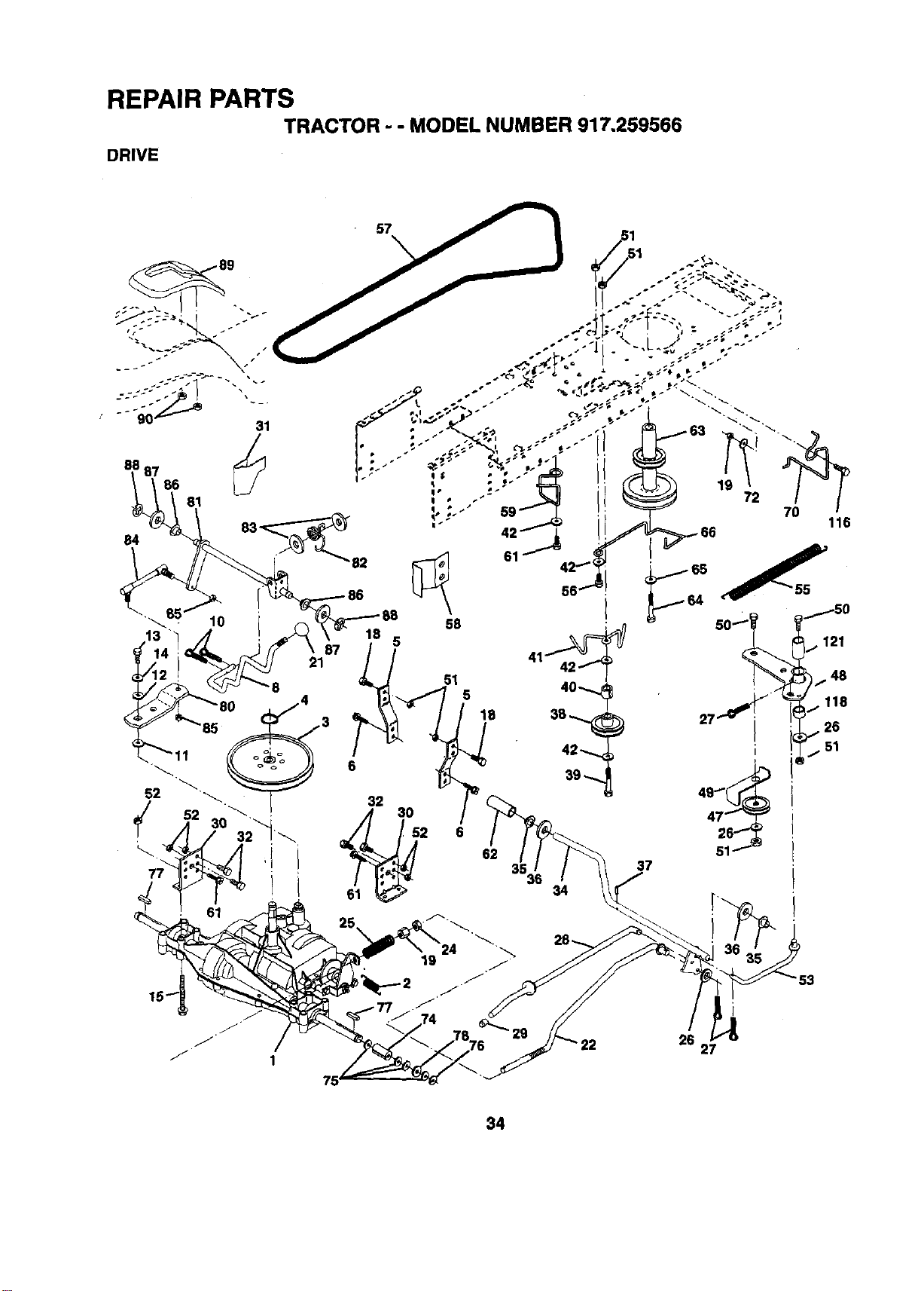
REPAIR PARTS
TRACTOR - - MODEL NUMBER 917.259566
DRIVE
57
84
83_82
10
18
87
21
5
51
5
62
37
26
27
34
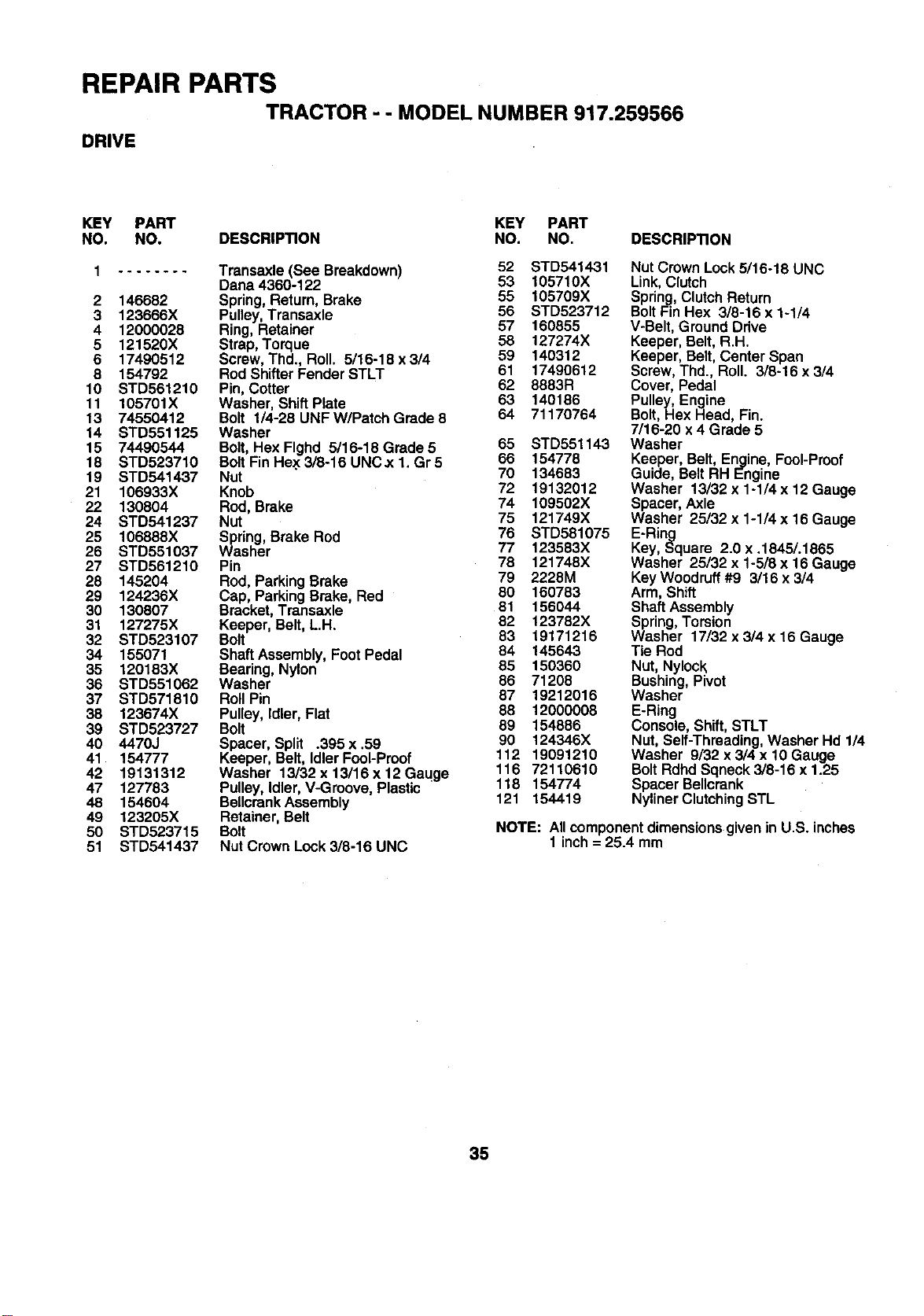
REPAIR PARTS
TRACTOR - - MODEL NUMBER 917.259566
DRIVE
KEY PART KEY PART
NO. NO. DESCRIPTION NO. NO. DESCRIPTION
1 ........ Transaxle (See Breakdown) 52 STD541431
Dana 4360-122 53 105710X
2 146682 Spring, Return,Brake 55 105709X
3 123666X Pulley,Transaxle 56 STD523712
4 12000028 Ring, Retainer 57 160855
5 121520X Strap,Torque 58 127274X
6 17490512 Screw, Thd., Roll. 5/16-18x3/4 59 140312
8 154792 Rod ShifterFender STLT 61 17490612
10 STD561210 Pin, Cotter 62 8883R
11 105701X Washer, Shift Plate 63 140186
13 74550412 Bolt 1/4-26 UNF W/Patch Grade 8 64 71170764
14 STD551125 Washer
15 74490544 Bolt, Hex Flghd 5/16-18 Grade 5 65 STD551143
18 STD523710 BoltFin Hex 3/8-16 UNC.x I Gr 5 66 154778
19 STD541437 Nut 70 134683
21 106933X Knob 72 19132012
22 130804 Rod, Brake 74 109502X
24 STD541237 Nut 75 121749X
25 106888X Spring, Brake Rod 76 STD581075
26 STD551037 Washer 77 123583X
27 STD561210 Pin 78 121748X
28 145204 Rod, ParkingBrake 79 2228M
29 124236X Cap, ParkingBrake, Red 80 160783
30 130807 Bracket,Transaxle 81 156044
31 127275X Keeper, Belt,L.H. 82 123782X
32 STD523107 Bolt 83 19171216
34 155071 Shaft Assembly,Foot Pedal 84 145643
35 120183X Bearing, Nylon 85 150360
36 STD551062 Washer 86 71208
37 STD571810 RollPin 87 19212016
38 123674X Pulley, Idler, Flat 88 12000008
39 STD523727 Bolt 89 154886
40 4470J Spacer, Split °395x .59 90 124346X
41 154777 Keeper, Belt, Idler Fool-Proof 112 19091210
42 19131312 Washer 13/32x13/16x12Gaqge 116 72110610
47 127783 Pulley, Idler,V-Groove, Plastic 118 154774
48 154604 BellcrenkAssembly 121 154419
49 123205X Retainer,Belt
50 STD523715 Bolt
51 STD541437 Nut Crown Look3/8-16 UNC
Nut Crown Look5/16-18 UNC
Link,Clutch
Spring,ClutchReturn
BoltFinHex 3/8-16 x 1-1/4
V-Belt,Ground Drive
Keeper, Belt, R.H.
Keeper, Belt, Center Span
Screw, Thd., Roll. 3/8-16 x 3/4
Cover, Pedal
Pulley, Engine
Bolt, Hex Head, Fin.
7/16-20 x 4 Grade 5
Washer
Keeper, Belt, Engine,Fool-Proof
Guide, Belt RH Engine
Washer 13/32 x 1-1/4 x 12 Gauge
Spacer, Axle
Washer 25/32 x 1-1/4 x 16 Gauge
E-Ring
Key, Square 2.0 x .1845/.1865
Washer 25/32 x 1-5/8 x 16 Gauge
Key Woodruff#9 3/16 x 3/4
Arm, Shift
ShaftAssembly
Spring,Torsion
Washer 17/32 x 3/4 x 16 Gauge
Tie Rod
Nut, Nylock
Bushing,Pivot
Washer
E-Ring
Console, Shift,STLT
Nut,Self-Threading,Washer Hd 1/4
Washer 9/32 x 3/4 x 10 Gauge
BoltRdhdSqneck 3/8-16 x 1.25
Spacer Be,crank
NylinerClutchingSTL
NOTE: Allcomponentdimensionsgivenin U.S. inches
1 inch= 25.4 mm
35
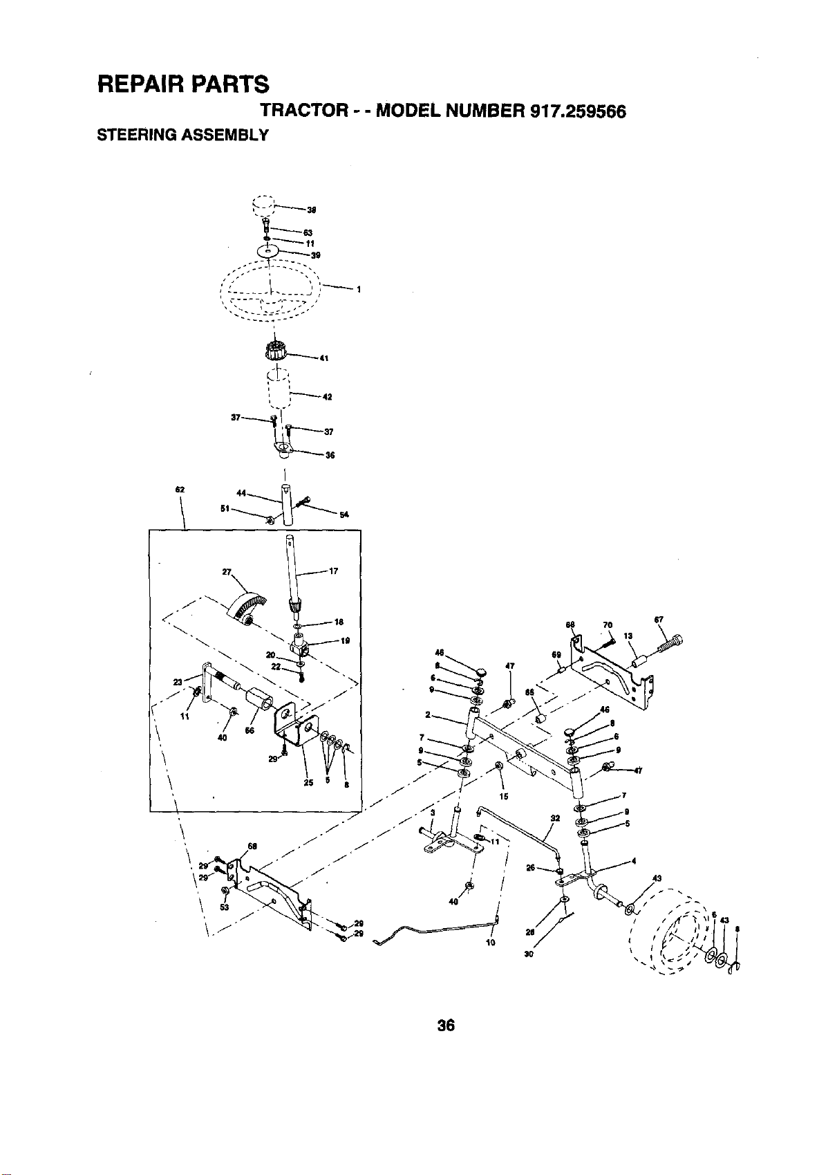
REPAIR PARTS
TRACTOR - - MODEL NUMBER 917.259566
STEERING ASSEMBLY
• p
62 44
27
67
66 70 13
36
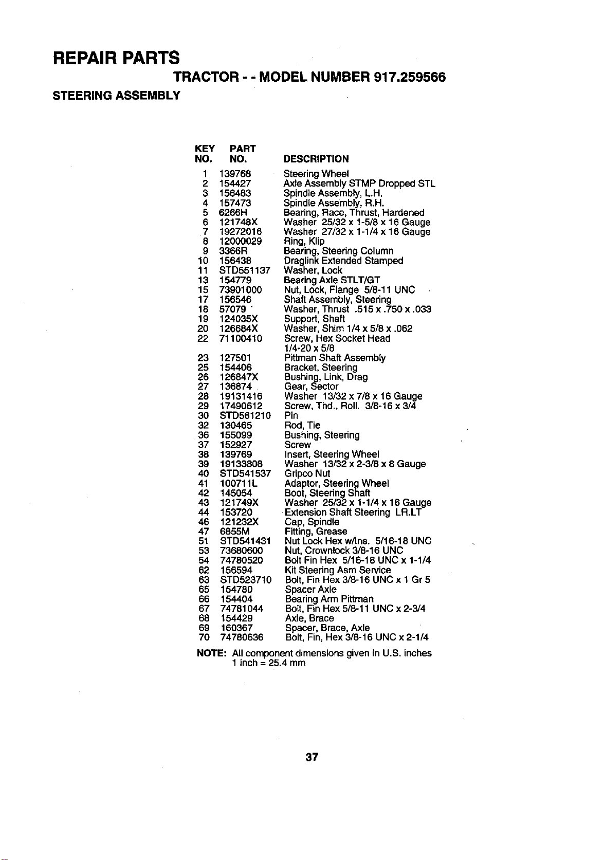
REPAIR PARTS
TRACTOR - - MODEL NUMBER 917.259566
STEERING ASSEMBLY
KEY PART
NO. NO. DESCRIPTION
1 139768
2 154427
3 156483
4 157473
5 6266H
6 121748X
7 19272016
8 12000029
9 3366R
10 156438
11 STD551137
13 154779
15 73901000
17 156546
18 57079 "
19 124035X
20 125884X
22 71100410
23 127501
25 154406
26 126847X
27 136874
28 19131416
29 17490612
30 STD561210
32 130465
36 155099
37 152927
38 139769
39 19133808
40 STD541537
41 100711L
42 145054
43 121749X
44 153720
46 121232X
47 6855M
51 STD541431
53 73680600
54 74780520
62 156594
63 STD523710
85 154780
66 154404
67 74781044
68 154429
69 160367
70 74780636
SteeringWheel
Axle AssemblySTMP Dropped STL
SpindleAssembly,L.H.
SpindleAssembly,R.H.
Bearing,Race, Thrust, Hardened
Washer 25/32 x !-5/8 x 16 Gauge
Washer 27/32 x 1-1/4 x 16 Gauge
Ring,Klip
Bearing,Steering Column
DraglinkExtendedStamped
Washer, Lock
BearingAxle STLT/GT
Nut, Lock,Flange 5/8-11 UNC
ShaftAssembly,Steering
Washer, Thrust .515 x .750 x .033
Support,Shaft
Washer, Shim 1/4x 5/8 x .062
Screw, Hex SocketHead
1/4-20 x 5/8
Pittman ShaftAssembly
Bracket, Steering
Bushing, Link, Drag
Gear, Sector
Washer 13/32 x 7/8 x 16 Gauge
Screw, Thd., Roll. 3/8-16 x 3/4
Pin
Rod, Tie
Bushing, Steering
Screw
Insert,SteeringWheel
Washer 13/32 x 2-3/8 x 8 Gauge
GripcoNut
Adaptor,SteeringWheel
Boot,SteeringShaft
Washer 25/32 x 1-1/4 x 16 Gauge
-Extension Shaft Steering LR.LT
Cap, Spindle
Fitting,Grease
Nut LockHexw/Ins. 5/16-18 UNC
Nut, Crownlock3/8-16 UNC
BoltFinHex 5/16-18 UNC x 1-1/4
KitSteeringAsm Service
Bolt, FinHex 3/8-16 UNC x 1 Gr 5
Spacer Axle
BearingArm Pittman
Bolt, FinHex 5/8-11 UNC x 2-3/4
Axle,Brace
Spacer, Brace,Axle
Bolt,Fin, Hex 3/8-16 UNC x 2-1/4
NOTE: Allcomponentdimensionsgivenin U.S. inches
1 inch= 25.4 mm
37
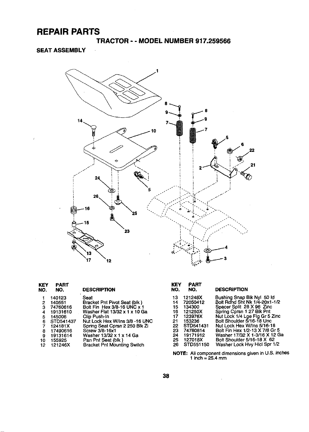
REPAIR PARTS
TRACTOR - - MODEL NUMBER 917.259566
SEAT ASSEMBLY
KEY
NO.
1
2
3
4
5
6
7
8
9
10
12
PART
NO,
140123
140551
74760616
19131610
145006
STD541437
124181X
17490616
19131614
155925
121245X
DESCRIPTION
Seat 13 121248X
Bracket Pnt Pivot Seat (blk) 14 72050412
Bolt Fin Hex 3/8-16 UNC x 1 15 134300
Washer Flat 13/32 x 1 x 10 Ga 16 121250X
Clip Push-In 17 123976X
Nut Lock Hex W/Ins 3/8 -16 UNC 21 153236
Spring Seat Cprsn 2 250 BIk Zi 22 STD541431
Screw 3/8-16xl 23 74780814
Washer 13/32 x 1 x 14 Ga 24 19171912
Pan Pnt Seat (blk) 25 127018X
Bracket Pnt Mounting Switch 26 STD551150
KEY PART
NO. NO. DESCRIPTION
BushingSnap BIk Nyl 50 Id
BoltRdhd ShtNk 1/4-20xl-112
Spacer Split 28 X 96 Zinc
SpringCprsn 1 27 BIk Pnt
Nut Lock 1/4 Lge FigGr 5 Zinc
BoltShoulder5/16-18 Unc
Nut Lock Hex W/Ins 5116-18
BoltFin Hex 1/2-13 X 718Gr 5
Washer 17/32 X 1-3/16 X 12 Ga
BoltShoulder5/16-18 X 62
Washer LockHvy HlclSpr 1/2
NOTE: Allcomponentdimensions givenin U.S. inches
1 inch= 25.4 mm
38
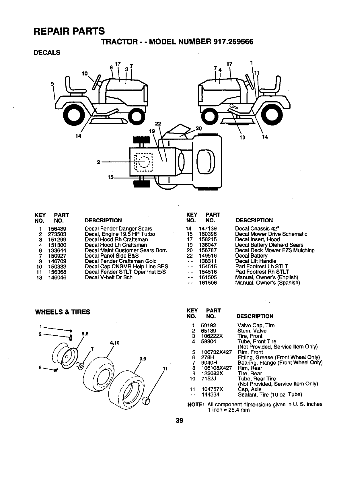
REPAIR PARTS
TRACTOR - - MODEL NUMBER 917.259566
DECALS
9
10
\
14
22
19
17
13 14
2
15
KEY PART KEY PART
NO. NO. DESCRIPTION NO. NO.
1 156439 Decal Fender Danger Sears 14 147139
2 273503 Decal, Engine 19.5 HP Turbo 15 150396
3 151299 DecaIHood Rh Craftsman 17 158215
4 151300 Decal Hood Lh Craftsman 19 138047
6 133644 Decal Maint Customer Sears Dom 20 156787
7 150927 Decal Panel Side B&S 22 149516
9 146709 Decal Fender CraftsmanGold - - 138311
10 150333 Decal Cap CNSMR Help LineSRS -- 154515
11 156368 Decal Fender STLT Oper InstE/S - - 154516
13 146046 Decal V-belt Dr Sch - - 161505
- - 161506
DESCRIPTION
Decal Chassis 42"
Decal Mower DriveSchematic
Decal Insert,Hood
Decal Battery Diehard Sears
Decal DeckMower EZ3 Mulching
Decal Battery
Decal Lift Handle
Pad Footrest Lh STLT
Pad Footrest Rh STLT
Manual, Owner's (English)
Manual, Owner's (Spanish)
WHEELS & TIRES
2 _ 5,8
4,10
7
11
39
KEY PART
NO. NO. DESCRIPTION
1
2
3
4
5
6
7
8
9
10
11
°.
59192
65139
106222X
59904
106732X427
278H
9040H
106108X427
122082X
7152J
104757X
144334
Valve Cap, Tire
Stem, Valve
Tire, Front
Tube, Front Tire
(Not Provided,Service Item Only)
Rim, Front
Fitting,Grease (FrontWheel Only)
Bearing, Flange (FrontWheel Only)
Rim, Rear
Tire, Rear
Tube, Rear Tire
(Not Provided, Service ItemOnly)
Cap, Axle
Sealant, Tire (10 oz. Tube)
NOTE: AIIcomponentdimensions givenin U. S. inches
1 inch= 25.4mm
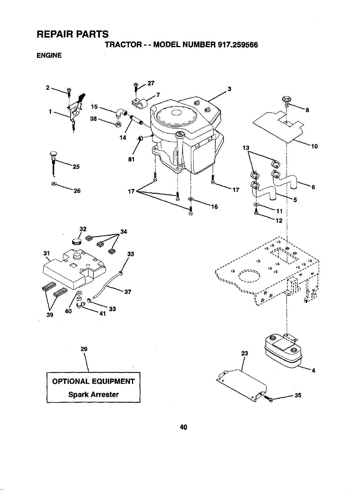
REPAIR PARTS
TRACTOR - - MODEL NUMBER 917.259566
ENGINE
2_
31
40
39
14
33
3
37
13 10
29
.\
I OPTIONAL EQUIPMENT I
Spark Arrester
40
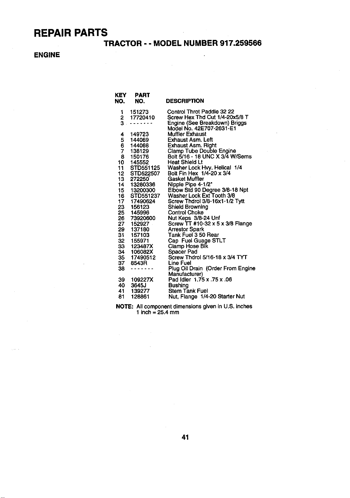
REPAIR PARTS
TRACTOR - - MODEL NUMBER 917.259566
ENGINE
KEY PART
NO. NO. DESCRIPTION
1 151273
2 17720410
3 .......
4 149723
5 144069
6 144068
7 138129
8 150176
10 145552
11 STD551125
12 STD522.507
13 27225_
14 13280335
15 13200300
16 STD551237
17 17490624
23 156123
25 145996
26 73920600
27 152927
29 137180
31 157103
32 155971
33 1234.87X
34 106082X
35 17490512
37 8543R
38
39 109227X
40 3645J
41 139277
81 128861
Control Thret Paddle 32 22
ScrewHex Thd Cut 1/4-20x5/8 T
Engine (See Breakdown)Briggs
Model No. 42E707-2631-E1
MufflerExhaust
ExhaustAsm. Left
ExhaustAsm. Right
Clamp Tube DoubleEngine
Bolt5/16 - 18 UNC X 3/4 W/Sems
Heat ShieldLt
Washer Lock Hvy. Helical 1/4
BoltFin Hex 1/4-20 x 3/4
Gasket Muffler
NipplePipe 4-1/2"
ElbowStd90 Degree 3/8-18 Npt
Washer LockExtTooth 3/8
ScrewThdrol3/8-16x1-1/2 Tytt
Shield Browning
ControlChoke
Nut Keps 3/8-24 Unf
ScrewTT #10-32 x 5 x 3/8 Flange
ArrestorSpark
Tank Fuel3 50 Rear
Cap FuelGuage STLT
Clamp Hose BIk
Spacer Pad
Screw Thdrol5/16-18 X3/4 TY'I"
Line Fuel
PlugOil Drain (Order From Engine
Manufacturer)
Pad Idler 1.75 x .75 x .06
Bushing
Stem Tank Fuel
Nut, Flange 1/4-20 Starter Nut
NOTE: AIIcomponentdimensionsgiven
1 inch= 25.4mm
in U.S. inches
41
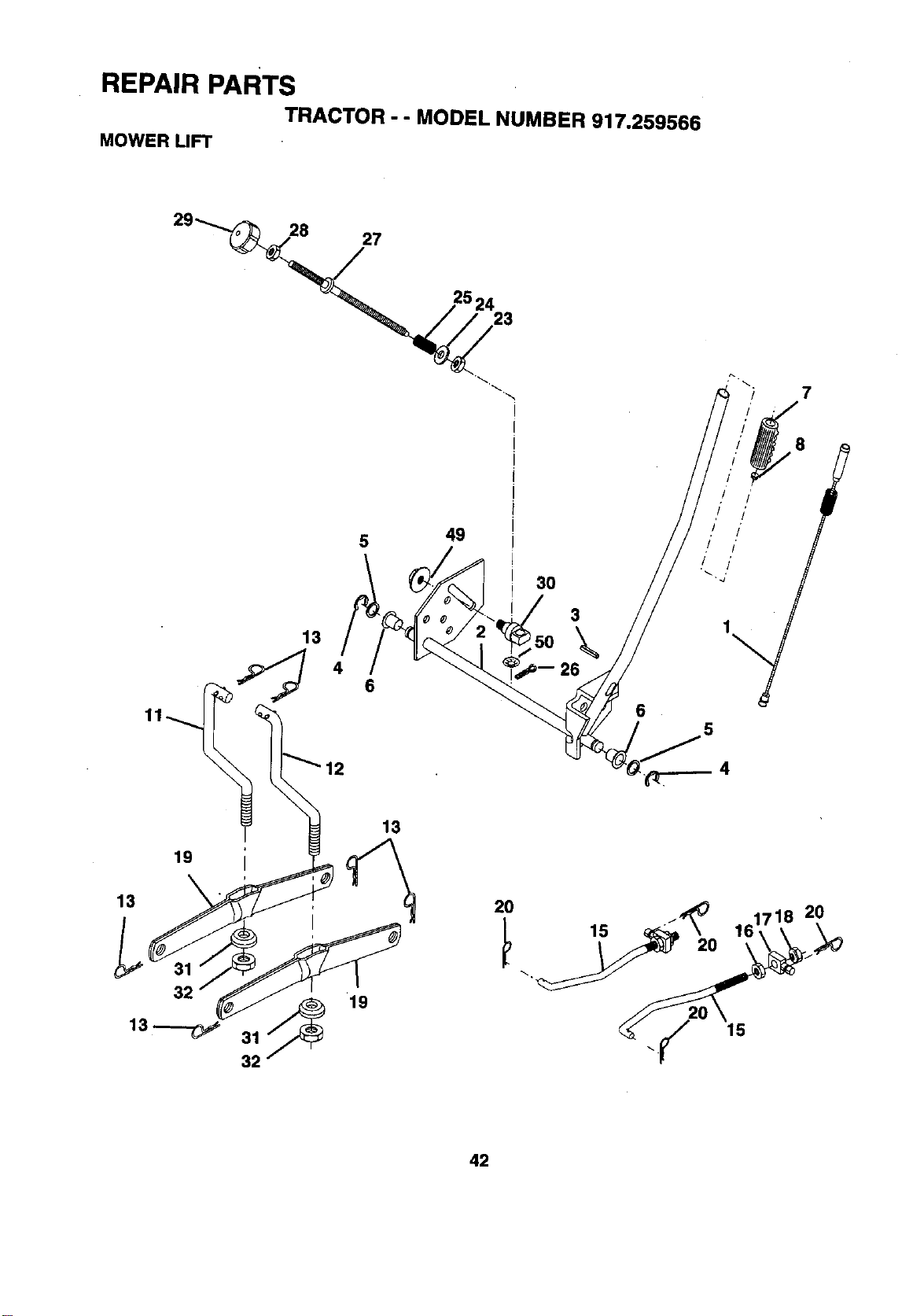
REPAIR PARTS
TRACTOR - - MODEL NUMBER 917.259566
MOWER LIFT
29_27
7
5
13
49
3O
3
\
6
8
,I I'
,! !'
.I I"
rI I'
5
4
13
19
2O
15
2O
15
2O
42
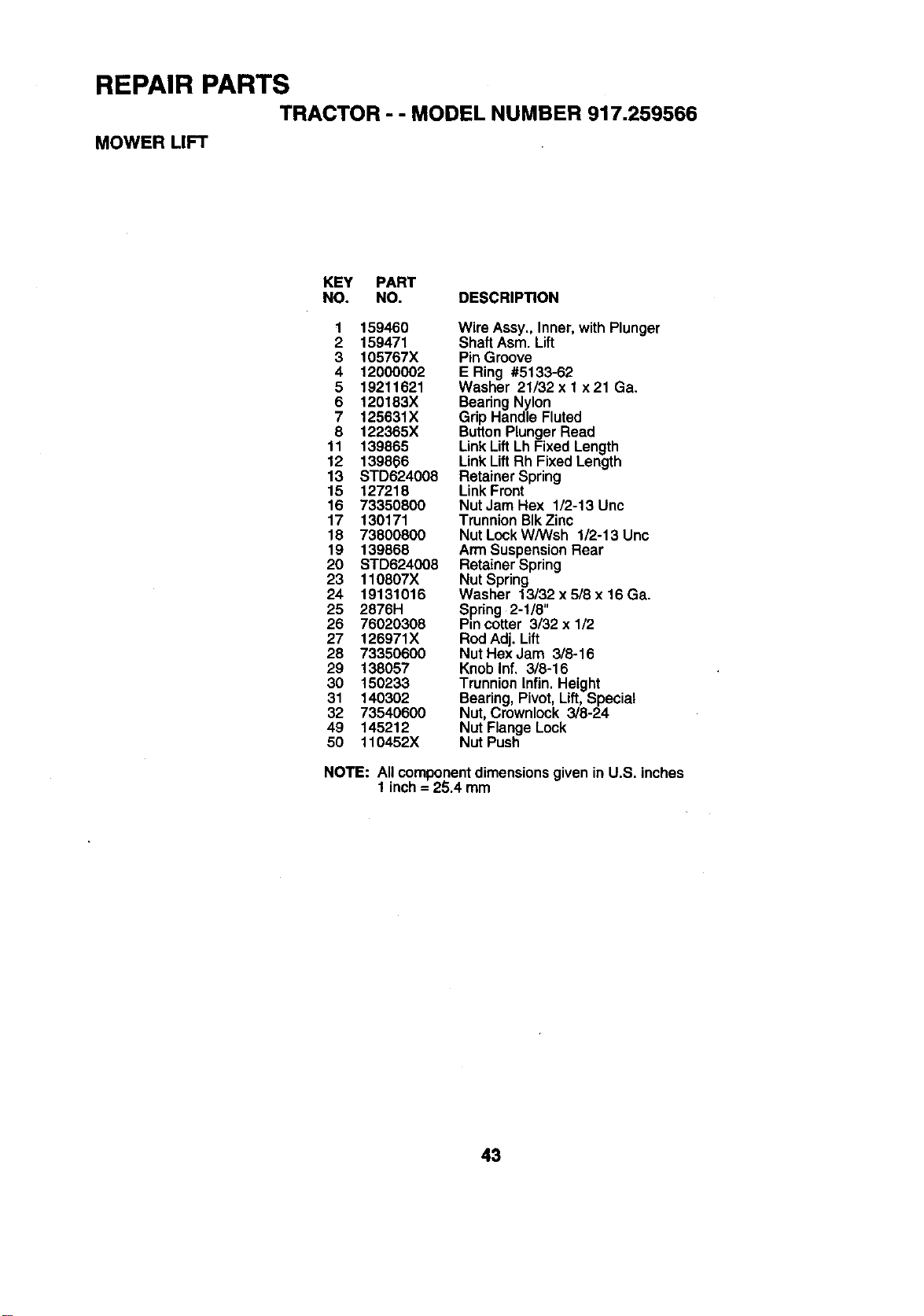
REPAIR PARTS
TRACTOR -- MODEL NUMBER 917.259566
MOWER LIFT
KEY PART
NO. NO. DESCRIP_ON
1 159460 Wire Assy., Inner,with Plunger
2 159471 Shaft Asm. Lift
3 105767X Pin Groove
4 12000002 E Ring #5133-62
5 19211621 Washer 21/32 x 1 x 21 Ga.
6 120183X Bearing Nylon
7 125631X Grip Handle Fluted
8 122365X ButtonPlungerRead
11 139865 Link Lift Lh Fixed Length
12 139866 Link Lift Rh Fixed Length
13 STD624008 Retainer Spring
15 127218 Link Front
16 73350800 Nut Jam Hex 1/2-13 Unc
17 130171 Trunnion BlkZinc
18 73800800 Nut Lock WANsh 1/2-13 Unc
19 139868 Arm SuspensionRear
20 STD624008 Retainer Spring
23 110807X Nut Spring
24 19131016 Washer 13/32 x 5/8 x 16 Ga.
25 2876H Spiring 2-1/8"
26 76020308 Pin cotter 3/32 x 1/2
27 126971X Rod Adj. Lift
28 73350600 Nut Hex Jam 3/8-16
29 138057 Knob Inf. 3/8-16
30 150233 Trunnion Infin. Height
31 140302 Bearing, Pivot, Lift, Special
32 73540600 Nut, Crownlock 3/8-24
49 145212 Nut Flange Lock
50 110452X Nut Push
NOTE: Allcomponentdimensions givenin U.S. inches
1 inch= 25.4 mm
43
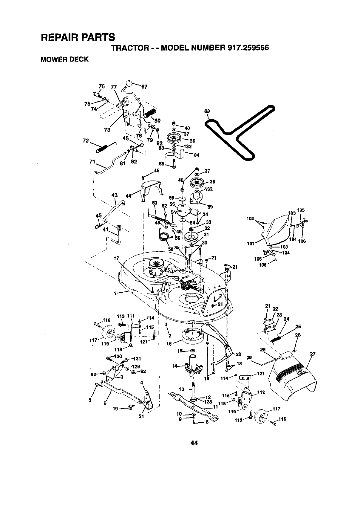
REPAIR PARTS
TRACTOR - - MODEL NUMBER 917.259566
MOWER DECK
76
58
,_'_'_104
105 .,_
106_
5
6
21
21
22
24
16
18
10----<
9"-_"
28 \
29
,18
26
27
44
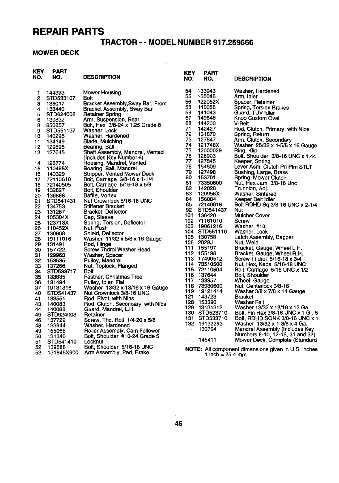
REPAIR PARTS
TRACTOR - - MODEL NUMBER 917.259566
MOWER DECK
KEY PART KEY PART
NO. NO. DESCRIPTION NO. NO. DESCRIPTION
1 144393
2 STD533107
3 138017
4 138440
5 STD624008
6 130832
8 850857
9 STD551137
10 140296
11 134149
12 129895
13 137645
Mower Housing 54 133943
Bolt 55 155046
BracketAssembly,Sway Bar, Front 56 122052X
BracketAssembly, Sway Bar 58 140086
Retainer Spring 59 141043
Arm, Suspension,Rear 67 149846
Bolt, Hex 3/8-24 x 1.25 Grade 8 68 144200
Washer, Lock 71 142427
Washer, Hardened 72 131870
Blade, Mulching 73 127847
74 121748X
Bearing, Ball
Shaft Assembly,Mandrel, Vented 75 12000029
(IncludesKey Number 6) 76 128903
14 128774 Housing,Mandrel, Vented 77 127845
15 110485X Bearing,Ball, Mandrel 78 154809
16 140329 Stripper,Vented Mower Oeck 79 127498
17 72110610 Bolt,Carriage 3/8-16 x1-1/4 80 153701
18 72140505 Bolt,Carriage 5/16-18x5/8 81 73350600
19 132827 Bolt,Shoulder 82 142028
20 136888 Baffle,Vortex 83 120958X
21 STD541431 Nut Crownlock 5/16-18 UNC 84 156084
22 134753 StiffenerBracket 85 72140618
23 131267 Bracket,Deflector 92 STD541437
24 105304X Cap, Sleeve 101 136420
25 123713X Spring,Torsion,Deflector 102 71161010
26 110452X Nut, Push 103 19061216
27 130968 Shield, Deflector 104 STD551110
28 19111016 Washer 11/32 x 5/8 x16 Gauge 105 130758
29 131491 Rod, Hinge 106 2029J
30 157722 Screw ThdrolWasher Head 111 155197
31 129963 Washer, Spacer 112 155198
32 153535 Pulley, Mandrel 113 17490512
33 137266 Nut, Toplock, Flanged 114 73510500
34 STD533717 Bolt 115 72110504
35 133835 Fastner,ChristmasTree 116 137644
117 133957
36 131494 Pulley, Idler,Flat
37 19131316 Washer 13/32 x13/16 x16 Gauge 118 73930600
40 STD541437 NutCrownlock3/8-16UNC 119 19121414
41 133551 Rod, Pivot,withNibs 121 143723
43 140083 Rod, Clutch,Secondary,with Nibs 128 153390
44 140088 Guard, Mandrel, L.H. 129 19131312
45 STD624003 Retainer 130 STD523710
46 137729 Screw, Thd. Roll 1/4-20 x 518 131 STD533710
48 133944 Washer, Hardened 132 19132293
49 155066 RollerAssembly,Cam Follower - - 130794
50 131340 Bolt,Shoulder #10-24Grade 5
51 STD541410 Locknut -- 145411
52 139888 Bolt, Shoulder 5/16-18 UNC
53 131845X900 Arm Assembly,Pad, Brake
Washer, Hardened
Arm,Idler
Spacer, Retainer
Spring,TorsionBrakes
Guard, TUV Idler
KnobCustomOval
V-Belt
Rod, Clutch,Primary,with Nibs
Spring,Return
Arm, Clutch, Secondary
Washer 25/32 x 1-5/8 x 16 Gauge
Ring, Klip
Bolt, Shoulder 3/8-16 UNC x 1.44
Keeper, Spring
Lever Asm. Clutch Pri PIm STLT
Bushing, Large, Brass
Spring, Mower Clutch
Nut, HexJam 3/8-16 Unc
Trunnion, Adj.
Washer, Sintered
Keeper Belt Idler
Bolt RDHD Sq 3/8-16 UNC x 2-1/4
Nut
Mulcher Cover
Screw
Washer #10
Washer, Lock
LatchAssembly, Bagger
Nut,Weld
Bracket,Gauge, Wheel L.H.
Bracket,Gauge, Wheel R.H.
ScrewThdrol 5/16-18 x 314
Nut,Hex, Keps 5/16-18 UNC
Bolt,Carriage 5/16 UNC x 1/2
Bolt,Shoulder
Wheel, Gauge
Nut,Centeriock 3/8-16
Washer 3/8 x 7/8 x 14 Gauge
Bracket
Washer Felt
Washer 13/32 x 13/16 x 12 Ga.
Bolt, Fin Hex 3/8-16 UNC x I Gr. 5
Bolt, RDHD SQNK 3/8-16 UNC x 1
Washer 13/32 x 1-3/8 x 4 Ga.
Mandrel Assembly (Includes Key
Numbers 8-10, 12-15, 31 and 32)
Mower Deck, Complete (Standard
NOTE: Allcomponentdimensions given in U.S. inches
1 inch= 25.4 mm
45
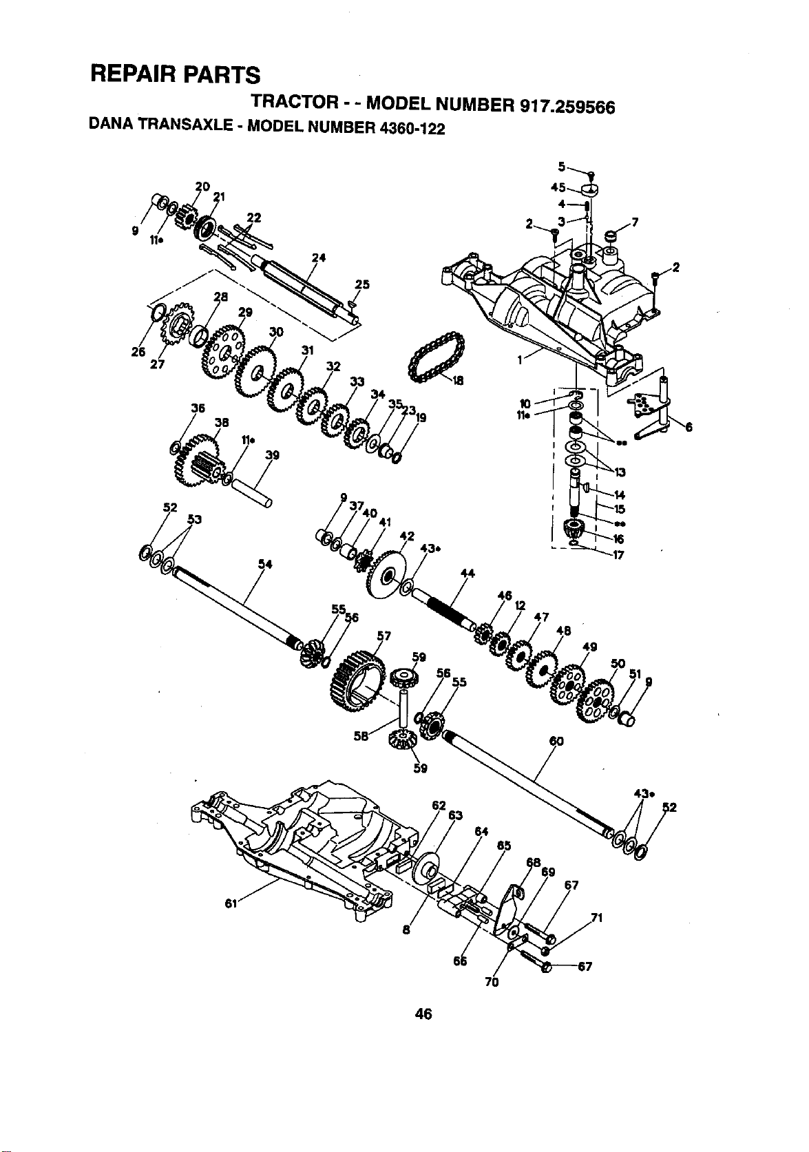
REPAIR PARTS
TRACTOR - - MODEL NUMBER 917.259566
DANA TRANSAXLE oMODEL NUMBER 4360-122
5
20 21 45_
22
24
25
2:
38
31
53
47
49
5O
62
7O
46
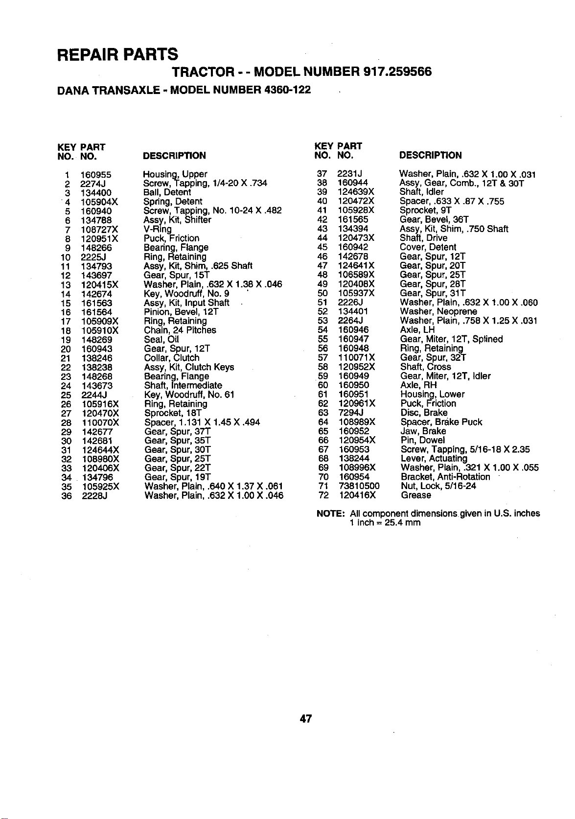
REPAIR PARTS
TRACTOR - - MODEL NUMBER 917.259566
DANA TRANSAXLE - MODEL NUMBER 4360-122
KEY PART KEY PART
NO. NO. DESCRIPTION NO. NO. DESCRIPTION
1 160955 Housing,Upper 37 2231J
2 2274J Screw,Tapping, 1/4-20 X .734 38 160944
3 134400 Ball, Detent 39 124639X
4 105904X Spring, Detent 40 120472X
5 160940 Screw, Tapping, No. 10-24 X.482 41 105928X
6 134788 Assy, Kit, Shifter 42 161565
7 108727X V-Ring 43 134394
8 120951X Puck, Friction 44 120473X
9 148266 Bearing, Flange 45 160942
10 2225J Ring, Retaining 46 142678
11 134793 Assy, Kit, Shim, .625 Shaft 47 124641X
12 143697 Gear, Spur, 15T 48 106589X
13 120415X Washer, Plain, .632 X 1.38 X .046 49 120408X
14 142674 Key, Woodruff, No. 8 50 105937X
15 161563 Assy, Kit, Input Shaft 5! 2226J
16 161564 Pinion, Bevel, 12T 52 134401
17 105909X Ring, Retaining 53 2264J
18 105910X Chain, 24 Pitches 54 160946
19 148269 Seal, Oil 55 160947
20 160943 Gear, Spur, 12T 56 160948
21 138246 Collar, Clutch 57 110071X
22 138238 Assy, Kit, Clutch Keys 58 120952X
23 148268 Bearing, Flange 59 160949
24 143673 Shaft, Intermediate 60 160950
25 2244J Key, Woodruff, No. 61 61 160951
26 105916X Ring, Retaining 62 120961X
27 120470X Sprocket, 18T 63 7294J
28 110070X Spacer, 1.131 X 1.45 X.494 64 108989X
29 142677 Gear, Spur, 37T 65 160952
30 142681 Gear, Spur, 35T 66 120954X
31 124644X Gear, Spur, 30T 67 160953
32 108980X Gear, Spur, 25T 68 138244
33 120406X Gear, Spur, 22T 69 108996X
34 134796 Gear, Spur, 19T 70 160954
35 105925X Washer, Plain, .640 X 1.37 X .061 71 73810500
36 2228J Washer, Plain, .632 X 1.00 X .046 72 120416X
Washer, Plain, .632 X 1.00 X .031
Assy, Gear, Comb., 12T & 30T
Shaft, Idler
Spacer, .633 X .87 X .755
Sprocket, 9T
Gear, Bevel, 36T
Assy, Kit, Shim, .750 Shaft
Shaft, Drive
Cover, Detent
Gear, Spur, 12T
Gear, Spur, 20T
Gear, Spur, 25T
Gear, Spur, 28T
Gear, Spur, 31T
Washer, Plain, .632 X 1.00 X .060
Washer, Neoprene
Washer, Plain, .758 X 1.25 X .031
Axle, LH
Gear, Miter, 12T, Sptined
Ring, Retaining
Gear, Spur, 32T
Shaft, Cross
Gear, Miter, 12T, Idler
Axle, RH
Housing,Lower
Puck, Friction
Disc,Brake
Spacer, Brake Puck
Jaw, Brake
Pin, Dowel
Screw, Tapping,5116-18 X 2.35
Lever,Actuating
Washer, Plain, .321 X 1.00 X .055
Bracket,Anti-Rotation
Nut, Lock,5/16-24
Grease
NOTE: All component dimensions given in U.S. inches
1 inch = 25.4 mm
47
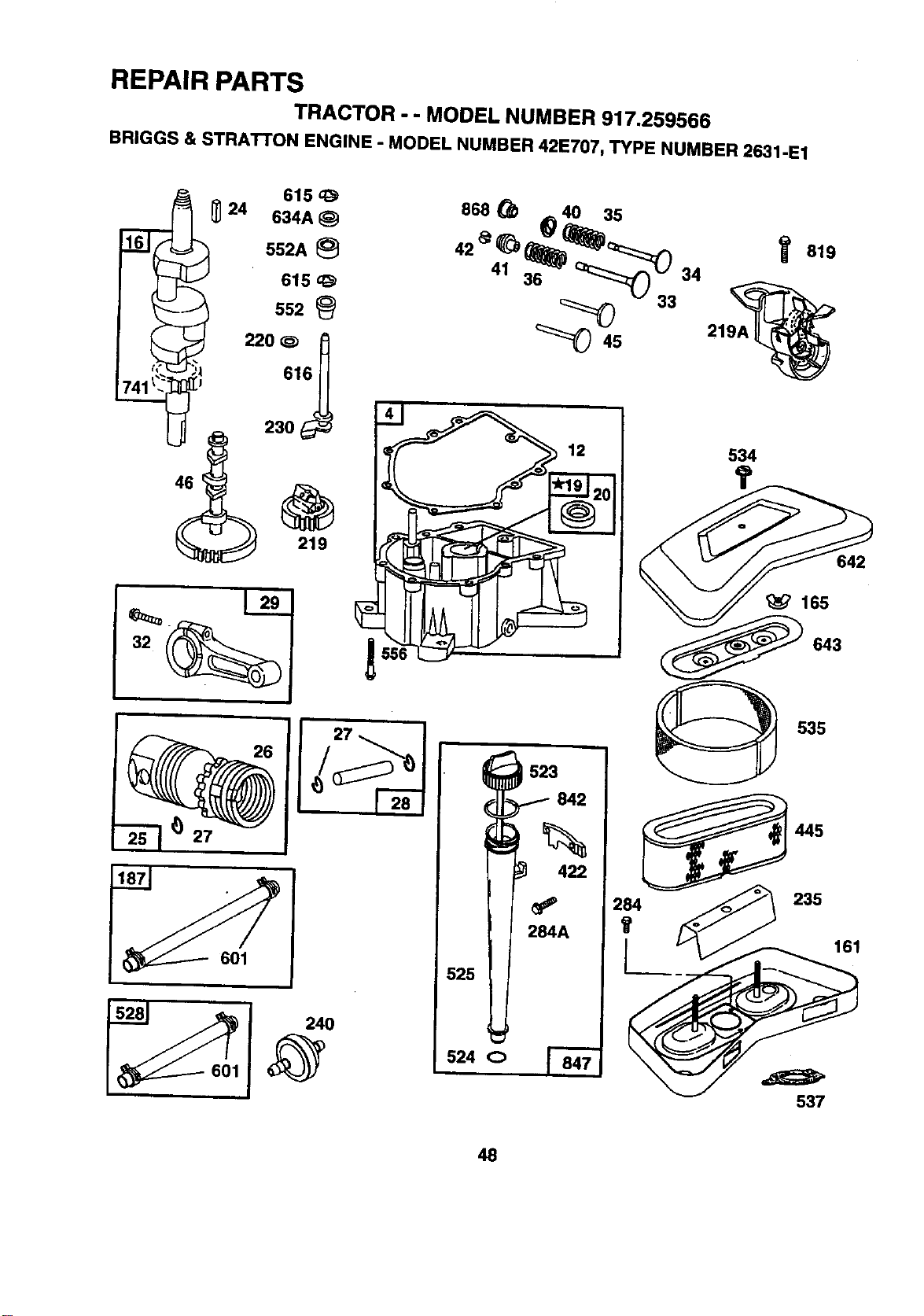
REPAIR PARTS
TRACTOR - - MODEL NUMBER 917.259566
BRIGGS & STRATTON ENGINE - MODEL NUMBER 42E707, TYPE NUMBER 2631-E1
I
552A
615
552
220 ¢_
_ 230
868 _ _ 40 35
42 _ _ _)_::::::z_
41 36 "_" Q_:::_.. 34
33
_45 219/
534
819
642
'_ 165
643
27
523
842
422
284A
525
524 o
535
445
2_4 _ 235
537
41t
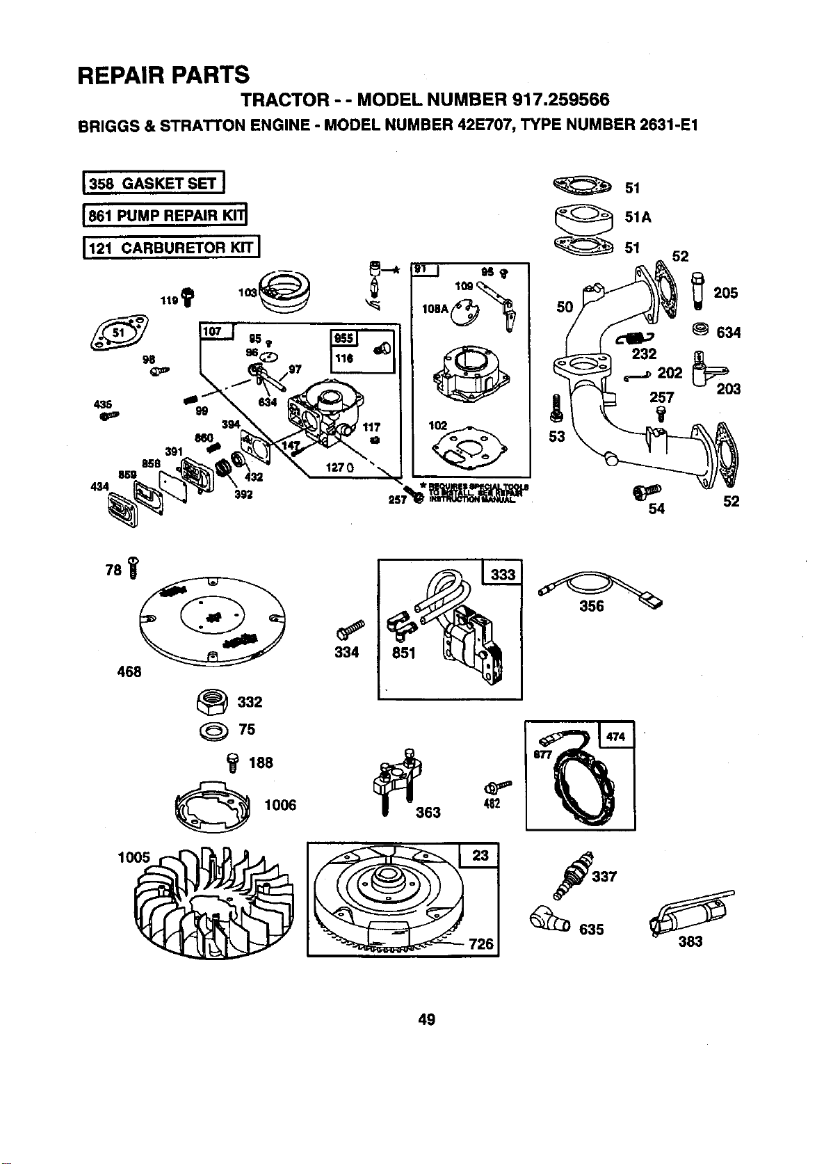
REPAIR PARTS
TRACTOR - - MODEL NUMBER 917.259566
BRIGGS & STRATTON ENGINE - MODEL NUMBER 42E707, TYPE NUMBER 2631-E1
127 0
108A_
51
51A
"" " 51
52
_205
634
_554 52
781
468
_332
75
1006
1005
334 851
63 _2
337
_635
49
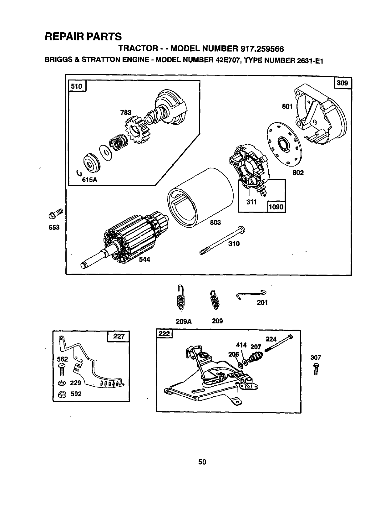
REPAIR PARTS
TRACTOR - - MODEL NUMBER 917.259566
BRIGGS & STRATTON ENGINE - MODEL NUMBER 421=707, TYPE NUMBER 2631-1=1
653
783
615A
311
803
801
802
209A 209
414 207_
307
5O
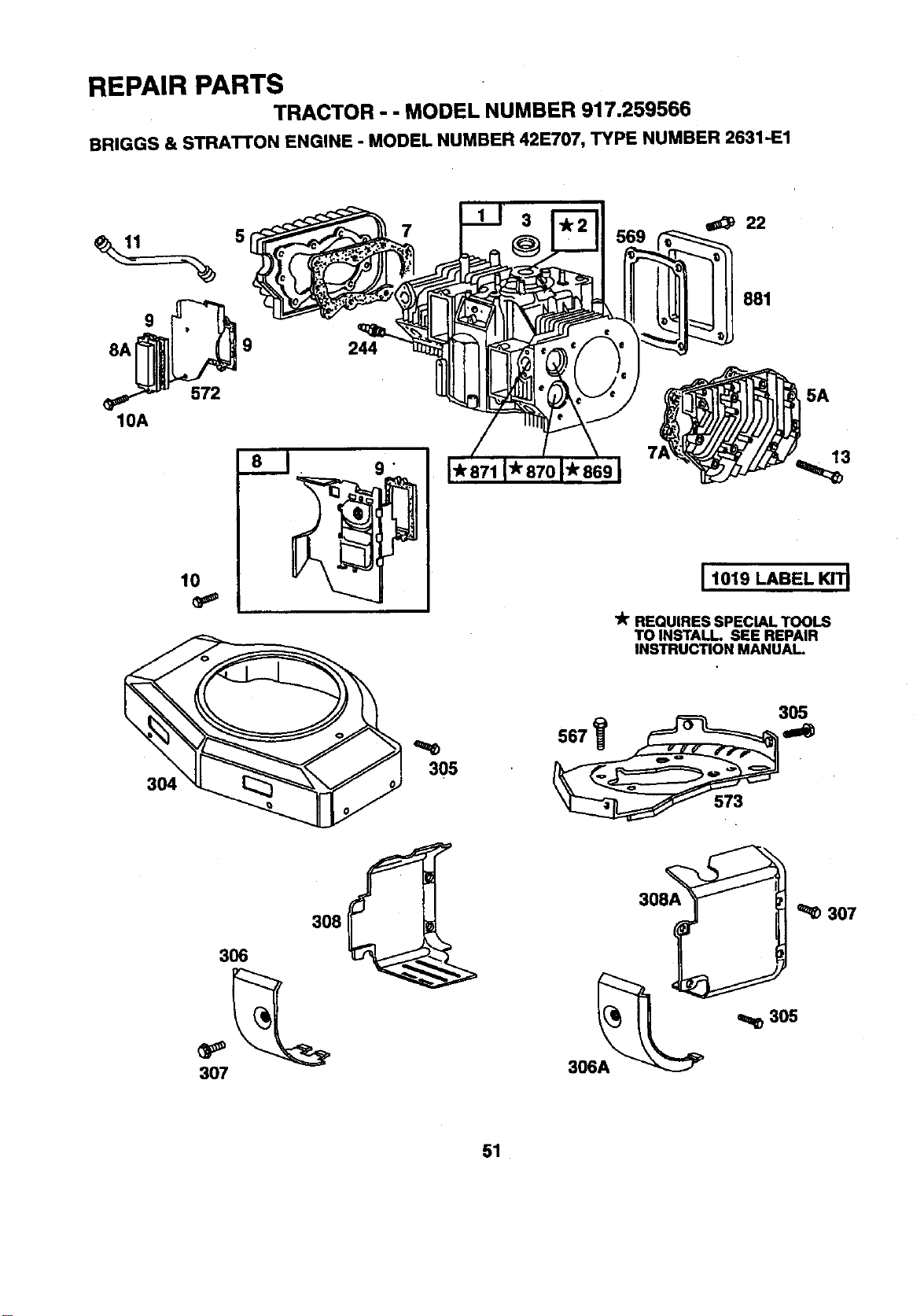
REPAIR PARTS
TRACTOR - - MODEL NUMBER 917.259566
BRIGGS & STRATTON ENGINE - MODEL NUMBER 42E707, TYPE NUMBER 2631'E1
5
9
8A 9
572
10A
lO
304
244
o
305
881
5A
13
I 1019 LABEL KIT_
lit REQUIRES SPECIAL TOOLS
TO INSTALL SEE REPAIR
INSTRUCTION MANUAL
567
305
307
30L_ ''LI_" _ 307
306A
51
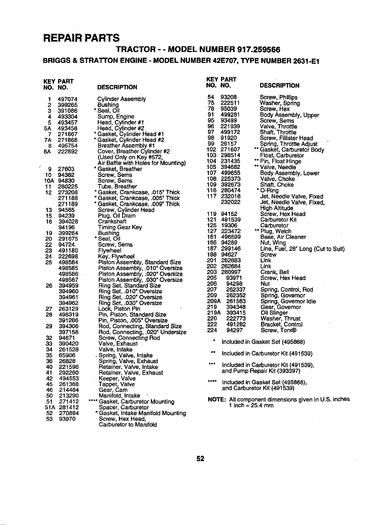
REPAIR PARTS
TRACTOR - - MODEL NUMBER 917.259566
BRIGGS & STRATTON ENGINE - MODEL NUMBER 42E707, TYPE NUMBER 2631-E1
KEY PART KEY PART
NO. NO. DESCRIPTION NO. NO. DESCRIPTION
1 497074
2 399265
3 391086
4 493304
5 493457
5A 493458
7 271867
7A 271868
8 495754
8A 222892
9 27603
10 94382
10A 94830
11 280225
12 273208
271188
271189
13 94565
15 94239
16 394028
94196
19 399264
20 291675
22 94724
23 491180
24 222698
25 498584
498585
498586
498587
26 394959
394960
394961
394962
27 263129
28 498319
391286
29 394306
397158
32 94671
33 390420
34 261528
35 65906
36 26828
40 221596
41 292260
42 494553
45 261368
46 214484
50 213290
51 271412
51A 281412
52 270884
53 93970
Cylinder Assembly 54 93208
Bushing 75 222511
*Seal, Oil 78 95039
Sump, Engine 91 499281
95 93499
Head, Cylinder#1 96 221939
Head, Cylinder#2 97 499172
* Gasket, CylinderHead #1
*Gasket, Cylinder Head #2 98 91920
BreatherAssembly#1 99 26157
Cover, Breather Cylinder #2 102 271607
103 298514
(Used Only on Key #572,
AirBaffle withHoles for Mounting) 104 231435
* Gasket, Breather 105 394682
Screw, Sems 107 499655
Screw, Sems 108 225373
Tube, Breather 109 392673
* Gasket,Crankcase, .0t5" Thick 116 280474
* Gasket, Crankcase, .005' Thick 117 232018
* Gasket, Crankcase, .009"Thick 232022
Screw, Cylinder Head
Plug, Oil Drain 119 94152
Crankshaft 121 491539
Timing Gear Key 125 19306
Bushing 127 223472
*Seal, Oil 161 496599
Screw, Seres 165 94289
Flywheel 187 299146
Key, Flywheel 188 94627
PistonAssembly, StandardSize 291 262683
PistonAssembly, .010" Oversize 202 262684
PistonAssembly,.020" Oversize 203 280997
PistonAssembly,.030" Oversize 205 93971
RingSet, StandardSize 206 94298
207 262337
RingSet, .010=Oversize 209 262352
RingSet, .020" Oversize
RingSet, .030" Oversize 209A 261563
Lock,PistonPin 219 394348
219A 393415
Pin, Piston, StandardSize
Pin, Piston, .005"Oversize 220 222773
222 491282
Rod, Connecting,StandardSize
Rod, Connecting,.020" Undersize 224 94297
Screw, ConnectingRed
Valve, Exhaust
Valve, Intake
• Spring,Valve, Intake
Spring,Valve, Exhaust
Retainer,Valve, Intake
Retainer,Valve, Exhaust
Keeper, Valve
Tappet, Valve
Gear, Cam
Manifold,Intake
.... Gasket, CarburetorMounting
Spacer, Carburetor
* Gasket, Intake ManifoldMounting
Screw, Hex Head,
Carburetorto Manifold
Screw, Phillips
Washer, Spring
Screw, Hex
BodyAssembly,Upper
Screw, Sems
Valve, Throttle
Shaft, Throttle
Screw, FiilisterHead
** Spring,ThrottleAdjust
Gasket, CarburetorBody
Float,Carburetor
** Pin, FloatHinge
** Valve, Needle
BodyAssembly,Lower
Valve, Choke
Shaft, Choke
* O-Ring
Jet, Needle Valve, Fixed
Jet, Needle Valve, Fixed,
High Altitude
Screw, Hex Head
Carburetor Kit
Carburetor
** Plug, Welch
Base, Air Cleaner
Nut, Wing
Line, Fuel, 28" Long (Cut to Suit)
Screw
Link
Link
Crank, Bell
Screw, Hex Head
Nut
Spring, Control,Rod
Spring,Governor
Spring,GovernorIdle
Gear, Govamor
Oil Slinger
Washer, Thrust
Bracket,Control
Screw, Torx_
Included in Gasket Set (495866)
** Included in Carburetor Kit (491539)
*** Includedin CarburetorKit (491539),
and Pump Repair Kit(393397)
.... Included in Gasket Set (495868),
and Carburetor Kit (491539)
NOTE: Allcomponentdimensionsgiven in U.S. inches
1 inch= 25.4 mm
52
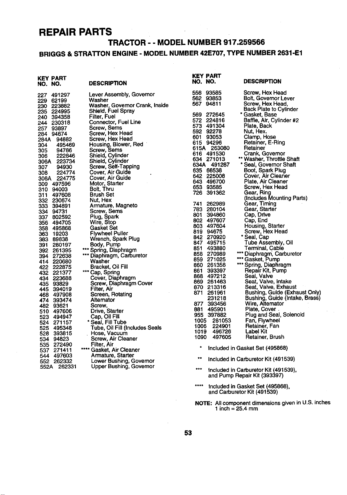
REPAIR PARTS
TRACTOR - - MODEL NUMBER 917.259566
BRIGGS & STRATrON ENGINE - MODEL NUMBER 42E707, TYPE NUMBER 2631-E1
KEY PART KEY PART
NO. NO. DESCRIPTION NO. NO. DESCRIPTION
227 491297 Lever Assembly, Govemor 556 93585
229 62199 Washer 562 93853
230 223882 Washer, GovemorCrank, lnside 567 94811
235 224995 Shield,Fuel Spray
240 394358 Filter,Fuel 569 272645
244 230318 Connector,Fuel Line 572 224816
257 93897 Screw, Sems 573 491304
284 94674 Screw, Hex Head 592 92278
284A 94882 Screw, Hex Head 601 93053
304 495469 Housing,Blower,Red 615 94296
305 94786 Screw, Sems 615A 263080
616 491530
306 222846 Shield,Cylinder 634 271013
306A 223734 Shield,Cylinder
307 94930 Screw, Serf-Tapping 634A 491287
308 224774 Cover, AirGuide 635 66538
308A 224775 Cover, AirGuide 642 225008
309 497596 Motor,Starter 643 496700
310 94003 Bolt,Thru 853 93585
311 497606 BrushSet 726 391362
332 230674 Nut, Hex
333 394891 Armature, Magneto 741 262989
334 94731 Screw, Sems 783 280104
337 802592 Plug, Spark 801 394860
355 494705 Wire, Stop 802 497607
358 495868 Gasket Set 803 497604
363 19203 FlywheeIPuller 819 94675
383 89838 Wrench, Spark Plug 842 270920
847 495715
391 280197 Body, Pump
392 261395 ***Spring, Diaphragm 851 493880
394 272638 *** Diaphragm,Carburetor 858 270989
414 220680 Washer 859 271025
422 222875 Bracket,Oil Fill 860 261358
432 221377 *** Cap, Spring 861 393397
868 497212
434 223688 Cover, Diaphragm
435 93829 Screw, DiaphragmCover 869 261463
445 394019 Filter,Air 870 213316
468 497908 Screen, Rotating 871 261961
474 393474 Altemator 231216
482 93621 Screw, 877 393456
510 497606 Drive, Starter 881 495901
523 494947 Cap, Oil Fill 955 397882
524 271157 *Seal, FilITube 1005 281053
525 495348 Tube, Oil Fill(IncludesSeals 1006 224901
526 393815 , Hose, Vacuum 1019 498726
534 94823 Screw, AirCleaner 1090 497605
535 272490 Filter,Air
537 271411 .... Gasket, AirCleaner
544 497603 Armature,Starter
552 262332 LowerBushing,Governor
552A 262331 Upper Bushing,Govemor
Screw, Hex Head
Bolt, GovernorLever
Screw, Hex Head,
Back Plate toCylinder
*Gasket, Base
Baffle,Air, Cylinder#2
Plate, Back
Nut, Hex.
Clamp, Hose
Retainer, E-Ring
Retainer
Crank, Governor
** Washer, ThrottleShaft
* Seal, GovernorShaft
Boot, Spark Plug
Cover, AirCleaner
Plate, Air Cleaner
Screw, Hex Head
Gear, Ring
(IncludesMounting Parts)
Gear, Timing
Gear, Starter
Cap, Ddve
Cap, End
Housing,Starter
Screw, Hex Head
* Seal, Cap
Tube Assembly,Oil
Terminal, Cable
*** Diaphragm,Carburetor
*** Gasket, Pump
*** Spring, Diaphragm
Repair Kit,Pump
Seal, Valve
Seat, Valve, intake
Seat, Valve, Exhaust
Bushing,Guide (ExhaustOnly)
Bushing,Guide (Intake, Brass)
Wire, Alternator
Plate, Cover.
Plugand Seal, Solenoid
Fan, Flywheel
Retainer,Fan
LabelKit
Retainer, Brush
Includedin Gasket Set (495868)
** Included in Carburetor Kit (491539)
*** Included in Carburetor Kit (491539),
and Pump Repair Kit (393397)
.... Includedin Gasket Set (495868),
and CarburetorKit (491539)
NOTE: Allcomponentdimensionsgivenin U.S. inches
1 inch=25.4 mm
53

ii i
SERVICE NOTES
i i
54

SUGGESTED GUIDE FOR SIGHTING SLOPES FOR SAFE OPERATION
ONLY RIDE UP AND DOWN HILL,
NOT ACROSS HILL
SIGHT AND HOLD THIS LEVEL WITH
SKY LINE OR TREE.
15° MAX.
__ perate your Tractor up and down the face of slopes (not I
greater than 15°), never across the face. Make turns gradu-
I
• ally to prevent tipping or !oss of control. Exercise extreme
caution when changing dlrectmn on slopes.
\
i\
SEARS
OWNER'S
MANUAL
MODEL NO.
917.259566
IF YOU NEED
REPAIR SERVICE
OR PARTS:
FOR REPAIR SERVICE, CALL
THIS TOLL FREE NUMBER:
1-800-4-REPAIR
(1-800-473-7247)
FOR REPLACEMENT PARTS
INFORMATION AND
ORDERING, CALL THIS
TOLL FREE NUMBER:
1-800-FON-PART
(1-800-366-7278)
FOR CONSUMER ASSISTANCE
HOT LINE, CALL THIS
TOLL FREE NUMBER:
1-800-659-5917
CRAFTSMAN®
19.5 HP
ELECTRIC START
42" MOWER
6 SPEED TRANSAXLE
LAWN TRACTOR
Each tractor has its own model number. Each engine has
its own model number.
The model number for your tractor will be found on the
model plate located under the seat.
The model number for your engine will be found on the
blower housing ofthe engine.
All parts listed herein may be ordered from any Seam,
Roebuck and Co. Service Center/Department and most Re-
tail Stores.
WHEN ORDERING REPAIR PARTS, ALWAYS GIVE THE
FOLLOWING INFORMATION:
• PRODUCT - TRACTOR
• MODEL NUMBER-917.259566
• ENGINE MODEL NO. - 42E707-2631-E1
", PART NUMBER
• PART DESCRIPTION
Your Sears merchandise has added value when you
consider Sears has service units nationwide staffed with
Sears trained technicians.., professional technicians
specifically trained to insure that we meet our pledge to
you, we service what we sell.
161505 8.12.97 JH Pdnted in U.S.A.
b


