Operator's Manual
CRRFTSMI:IN°
LAWN TRACTOR
18.5 HP, 42" Mower
Electric Start
6 Speed Transaxle
Model No.
917.276410 \ 276411
276412
• Espahol, p. 33
_]] his product has a low emission engine which operates
differently from previously built engines. Before you start the
engine, read and understand this Owner's Manual.
IMPORTANT:
Read and follow all Safety
Rules and Instructions before
operating this equipment.
For answers to your questions about
this product, Call:
1-800-659-5917
Sears Craftsman Help Line
5 am - 5 pm, Mon - Sat
Sears, Roebuck and Co., Hoffman Estates, IL 60179 U.S.A.
Visit our Craftsman website:www.sears.com/craftsman

Warranty.................................................2
SafetyRules...........................................3
ProductSpecifications............................6
Assembly/Pre-Operation........................8
Operation..............................................11
MaintenanceSchedule.........................17
Maintenance.........................................17
Service andAdjustments......................22
Storage.................................................28
Troubleshooting....................................29
Sears Service.........................Back Cover
LIMITED WARRANTY ON CRAFTSMAN TRACTOR AND BATTERY
2-YEAR ON TRACTOR
When used and maintained according to the operator's manual instructions, if this tractor
fails due to a defect in material or workmanship within two years from the date of pur-
chase, call 1-800-4-MY-HOME® to arrange for free repair.
During the first 30 days of purchase, there will be no charge to service the product in
your home. For your convenience, in-home warranty service will still be available after
the first 30 days of purchase, but a trip charge will apply. This charge will be waived if
you transport the product to an authorized Craftsman drop-off location. For the nearest
authorized location, call 1-800-4-MY-HOME®.
Tractor warranty coverage does not include:
• Expendable items which become worn during normal use, including but not limited to
blades, spark plugs, air cleaners, belts, and oil filters.
• Standard maintenance servicing, oil changes, or tune-ups.
• Tire replacement or repair caused by punctures from outside objects, such as nails,
thorns, stumps, or glass.
• Repairs necessary because of operator abuse, including but not limited to damage
caused by towing objects beyond the capability of the tractor, impacting objects that
bend the frame or crankshaft, or over-speeding the engine.
• Repairs necessary because of operator negligence, including but not limited to electri-
cal and mechanical damage caused by improper storage, failure to use the proper
grade and amount of engine oil, failure to keep the deck clear of flammable debris,
or failure to maintain the equipment according to the instructions contained in the
operator's manual.
• Engine (fuel system) cleaning or repairs necessary because of fuel determined to be
contaminated or oxidized (stale). In general, fuel should be used within 30 days of its
purchase date.
• Normal deterioration and wear of the exterior finishes, or product label replacement.
• The tractor battery, which is covered for only 90 days as stated below.
90-DAYS ON BATTERY
For ninety (90) days from the date of purchase, if the battery included with this tractor is
defective in material or workmanship (our testing proves it will not hold a charge), it will
be replaced free of charge.
During the first 30 days of purchase, there will be no charges to replace the battery in
your home. For your convenience, in-home warranty service will still be available after
the first 30 days of purchase, but a trip charge will apply. This charge will be waived if
you transport the battery to an authorized Craftsman drop-off location. For the nearest
authorized location, call 1-800-4-MY-HOME®.
All tractor and battery warranty coverage is void if this product is used for commercial or
rental purposes.
This warranty applies only while this product is within the United States.
This warranty gives you specific legal rights, and you may also have other rights, which
vary, from state to state.
Sears, Roebuck and Co., Hoffman Estates, IL 60179
DANGER:This cutting machine is capable of amputating hands and feet and
throwing objects. Failure to observe the following safety instructions could result
in serious injury or death.
,_WARNING: In order to prevent ac-
cidental starting when setting up, trans-
porting, adjusting or making repairs,
always disconnect spark plug wire and
place wire where it cannot contact spark
plug.
_WARNING: Do not coast down a hill in
neutral, you may lose control of the tractor.
_WARNING: Tow only the attachments
that are recommended by and comply with
specifications of the manufacturer of your
tractor. Use common sense when towing.
Operate only at the lowest possible speed
when on a slope. Too heavy of a load,
while on a slope, is dangerous. Tires can
lose traction with the ground and cause
you to lose control of your tractor.
,_WARNING: Engine exhaust, some of
its constituents, and certain vehicle com-
ponents contain or emit chemicals known
to the State of California to cause cancer
and birth defects or other reproductive
harm.
,_WARNING: Battery posts, terminals
and related accessories contain lead and
lead compounds, chemicals known to the
State of California to cause cancer and
birth defects or other reproductive harm.
Wash hands after handling.
I. GENERAL OPERATION
• Read, understand, and follow all instruc-
tions on the machine and in the manual
before starting.
• Do not put hands or feet near rotating
parts or under the machine. Keep clear
of the discharge opening at all times.
• Only allow responsible adults, who are
familiar with the instructions, to operate
the machine.
• Clear the area of objects such as rocks,
toys, wire, etc., which could be picked
up and thrown by the blades.
• Be sure the area is clear of bystand-
ers before operating. Stop machine if
anyone enters the area.
• Never carry passengers.
• Do not mow in reverse unless abso-
lutely necessary. Always look down and
behind before and while backing.
• Never direct discharged material toward
anyone. Avoid discharging material
against a wall or obstruction. Material
may ricochet back toward the operator.
Stop the blades when crossing gravel
surfaces.
• Do not operate machine without the
entire grass catcher, discharge guard,
or other safety devices in place and
working.
• Slow down before turning.
• Never leave a running machine unat-
tended. Always turn off blades, set
parking brake, stop engine, and remove
keys before dismounting.
• Disengage blades when not mowing.
Shut off engine and wait for all parts to
come to a complete stop before clean-
ing the machine, removing the grass
catcher, or unclogging the discharge
guard.
• Operate machine only in daylight or
good artificial light.
• Do not operate the machine while under
the influence of alcohol or drugs.
• Watch for traffic when operating near or
crossing roadways.
• Use extra care when loading or unload-
ing the machine into a trailer or truck.
• Always wear eye protection when oper-
ating machine.
• Data indicates that operators, age 60
years and above, are involved in a large
percentage of riding mower-related in-
juries. These operators should evaluate
their ability to operate the riding mower
safely enough to protect themselves
and others from serious injury.
• Follow the manufacturer's recommen-
dation for wheel weights or counter-
weights.
• Keep machine free of grass, leaves or
other debris build-up which can touch
hot exhaust / engine parts and burn.
Do not allow the mower deck to plow
leaves or other debris which can cause
build-up to occur. Clean any oil or fuel
spillage before operating or storing the
machine. Allow machine to cool before
storage.
3
I1. SLOPE OPERATION
Slopes are a major factor related to loss of
control and tip-over accidents, which can
result in severe injury or death. Opera-
tion on all slopes requires extra caution. If
you cannot back up the slope or if you feel
uneasy on it, do not mow it.
• Mow up and down slopes, not across.
• Watch for holes, ruts, bumps, rocks, or
other hidden objects. Uneven terrain
could overturn the machine. Tall grass
can hide obstacles.
• Choose a low ground speed so that you
will not have to stop or shift while on the
slope.
• Do not mow on wet grass. Tires may
lose traction.
Always keep the machine in gear when
going down slopes. Do not shift to neu-
tral and coast downhill.
• Avoid starting, stopping, or turning on a
slope. If the tires lose traction, disen-
gage the blades and proceed slowly
straight down the slope.
• Keep all movement on the slopes slow
and gradual. Do not make sudden
changes in speed or direction, which
could cause the machine to roll over.
• Use extra care while operating machine
with grass catchers or other attach-
ments; they can affect the stability of the
machine. Do no use on steep slopes.
• Do not try to stabilize the machine by
putting your foot on the ground.
• Do not mow near drop-offs, ditches,
or embankments. The machine could
suddenly roll over if a wheel is over the
edge or if the edge caves in.
III. CHILDREN
Tragic accidents can occur if the operator
is not alert to the presence of children.
Children are often attracted to the machine
and the mowing activity. Never assume
that children will remain where you last
saw them.
• Keep children out of the mowing area
and in the watchful care of a responsible
adult other than the operator.
• Be alert and turn machine off if a child
enters the area.
• Before and while backing, look behind
and down for small children.
• Never carry children, even with the
blades shut off. They may fall off and
be seriously injured or interfere with
safe machine operation. Children who
have been given rides in the past may
suddenly appear in the mowing area for
another ride and be run over or backed
over by the machine.
• Never allow children to operate the
machine.
• Use extra care when approaching blind
corners, shrubs, trees, or other objects
that may block your view of a child.
IV. TOWING
• Tow only with a machine that has a
hitch designed for towing. Do not attach
towed equipment except at the hitch
point.
• Follow the manufacturer's recommenda-
tion for weight limits for towed equip-
ment and towing on slopes.
• Never allow children or others in or on
towed equipment.
• On slopes, the weight of the towed
equipment may cause loss of traction
and loss of control.
• Travel slowly and allow extra distance to
stop.
V. SERVICE
SAFE HANDLING OF GASOLINE
To avoid personal injury or property
damage, use extreme care in handling
gasoline. Gasoline is extremely flammable
and the vapors are explosive.
• Extinguish all cigarettes, cigars, pipes,
and other sources of ignition.
• Use only approved gasoline container.
• Never remove gas cap or add fuel with
the engine running. Allow engine to cool
before refueling.
• Never fuel the machine indoors.
• Never store the machine or fuel con-
tainer where there is an open flame,
spark, or pilot light such as on a water
heater or other appliances.
• Never fill containers inside a vehicle or
on a truck or trailer bed with plastic liner.
Always place containers on the ground
away from your vehicle when filling.
• Remove gas-powered equipment from
the truck or trailer and refuel it on the
ground. If this is not possible, then
refuel such equipment with a portable
container, rather than from a gasoline
dispenser nozzle.
• Keep the nozzle in contact with the rim
of the fuel tank or container opening at
all times until fueling is complete. Do not
use a nozzle lock-open device.
• If fuel is spilled on clothing, change
clothing immediately.
• Never overfill fuel tank. Replace gas cap
and tighten securely.
GENERAL SERVICE
• Never operate machine in a closed area.
• Keep all nuts and bolts tight to be sure
the equipment is in safe working condi-
tion.
• Never tamper with safety devices. Check
their proper operation regularly.
• Keep machine free of grass, leaves, or
other debris build-up. Clean oil or fuel
spillage and remove any fuel-soaked
debris. Allow machine to cool before
storing.
• If you strike a foreign object, stop and
inspect the machine. Repair, if neces-
sary, before restarting.
• Never make any adjustments or repairs
with the engine running.
• Check grass catcher components and
the discharge guard frequently and
replace with manufacturer's recom-
mended parts, when necessary.
• Mower blades are sharp. Wrap the
blade or wear gloves, and use extra
caution when servicing them.
• Check brake operation frequently. Ad-
just and service as required.
• Maintain or replace safety and instruc-
tion labels, as necessary.
• Be sure the area is clear of bystand-
ers before operating. Stop machine if
anyone enters the area.
• Never carry passengers.
• Do not mow in reverse unless abso-
lutely necessary. Always look down and
behind before and while backing.
• Never carry children, even with the
blades shut off. They may fall off and
be seriously injured or interfere with
safe machine operation. Children who
have been given rides in the past may
suddenly appear in the mowing area for
another ride and be run over or backed
over by the machine.
• Keep children out of the mowing area
and in the watchful care of a responsible
adult other than the operator.
• Be alert and turn machine off if a child
enters the area.
• Before and while backing, look behind
and down for small children.
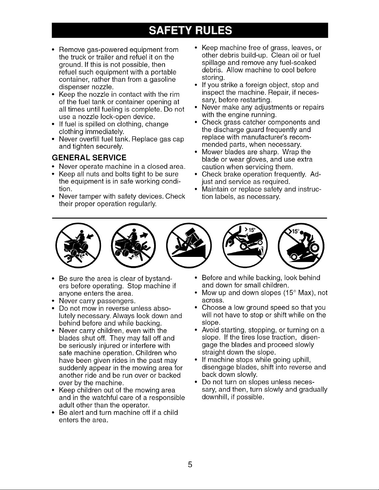
• Mow up and down slopes (15 ° Max), not
across.
• Choose a low ground speed so that you
will not have to stop or shift while on the
slope.
• Avoid starting, stopping, or turning on a
slope. If the tires lose traction, disen-
gage the blades and proceed slowly
straight down the slope.
• If machine stops while going uphill,
disengage blades, shift into reverse and
back down slowly.
• Do not turn on slopes unless neces-
sary, and then, turn slowly and gradually
downhill, if possible.
5
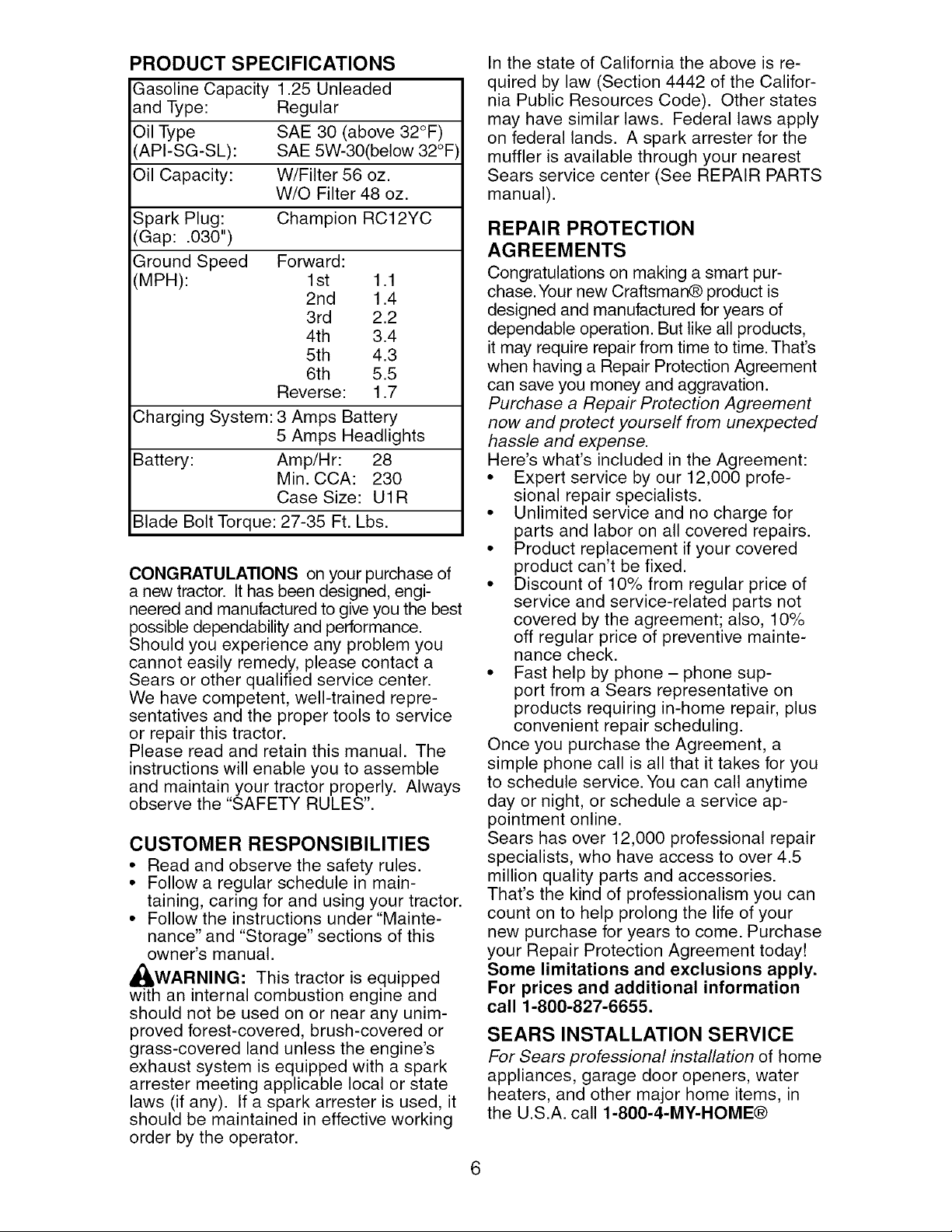
PRODUCT SPECIFICATIONS
Gasoline Capacity 1.25 Unleaded
and Type: Regular
Oil Type SAE 30 (above 32°F)
'API-SG-SL): SAE 5W-30(below 32°F
Oil Capacity: W/Filter 56 oz.
W/O Filter 48 oz.
Spark Plug: Champion RC12YC
(Gap: .030")
Ground Speed Forward:
(MPH): 1st 1.1
2nd 1.4
3rd 2.2
4th 3.4
5th 4.3
6th 5.5
Reverse: 1.7
Charging System: 3 Amps Battery
5 Amps Headlights
Battery: Amp/Hr: 28
Min. CCA: 230
Case Size: U1R
Blade Bolt Torque: 27-35 Ft. Lbs.
CONGRATULATIONS on your purchase of
a new tractor. It has been designed, engi-
neered and manufactured to give you the best
possible dependability and performance.
Should you experience any problem you
cannot easily remedy, please contact a
Sears or other qualified service center.
We have competent, well-trained repre-
sentatives and the proper tools to service
or repair this tractor.
Please read and retain this manual. The
instructions will enable you to assemble
and maintain your tractor properly. Always
observe the "SAFETY RULES".
CUSTOMER RESPONSIBILITIES
• Read and observe the safety rules.
• Follow a regular schedule in main-
taining, caring for and using your tractor.
• Follow the instructions under "Mainte-
nance" and "Storage" sections of this
owner's manual.
_,WARNING: This tractor is equipped
with an internal combustion engine and
should not be used on or near any unim-
proved forest-covered, brush-covered or
grass-covered land unless the engine's
exhaust system is equipped with a spark
arrester meeting applicable local or state
laws (if any). If a spark arrester is used, it
should be maintained in effective working
order by the operator.
In the state of California the above is re-
quired by law (Section 4442 of the Califor-
nia Public Resources Code). Other states
may have similar laws. Federal laws apply
on federal lands. A spark arrester for the
muffler is available through your nearest
Sears service center (See REPAIR PARTS
manual).
REPAIR PROTECTION
AGREEMENTS
Congratulations on making a smart pur-
chase. Your new Craftsman® product is
designed and manufactured for years of
dependable operation. But like all products,
it may require repair from time to time. That's
when having a Repair Protection Agreement
can save you money and aggravation.
Purchase a Repair Protection Agreement
now and protect yourself from unexpected
hassle and expense.
Here's what's included in the Agreement:
• Expert service by our 12,000 profe-
sional repair specialists.
• Unlimited service and no charge for
parts and labor on all covered repairs.
• Product replacement if your covered
product can't be fixed.
• Discount of 10% from regular price of
service and service-related parts not
covered by the agreement; also, 10%
off regular price of preventive mainte-
nance check.
• Fast help by phone- phone sup-
port from a Sears representative on
products requiring in-home repair, plus
convenient repair scheduling.
Once you purchase the Agreement, a
simple phone call is all that it takes for you
to schedule service. You can call anytime
day or night, or schedule a service ap-
pointment online.
Sears has over 12,000 professional repair
specialists, who have access to over 4.5
million quality parts and accessories.
That's the kind of professionalism you can
count on to help prolong the life of your
new purchase for years to come. Purchase
your Repair Protection Agreement today!
Some limitations and exclusions apply.
For prices and additional information
call 1-800-827-6655.
SEARS INSTALLATION SERVICE
For Sears professional installation of home
appliances, garage door openers, water
heaters, and other major home items, in
the U.S.A. call 1-800-4-MY-HOME®
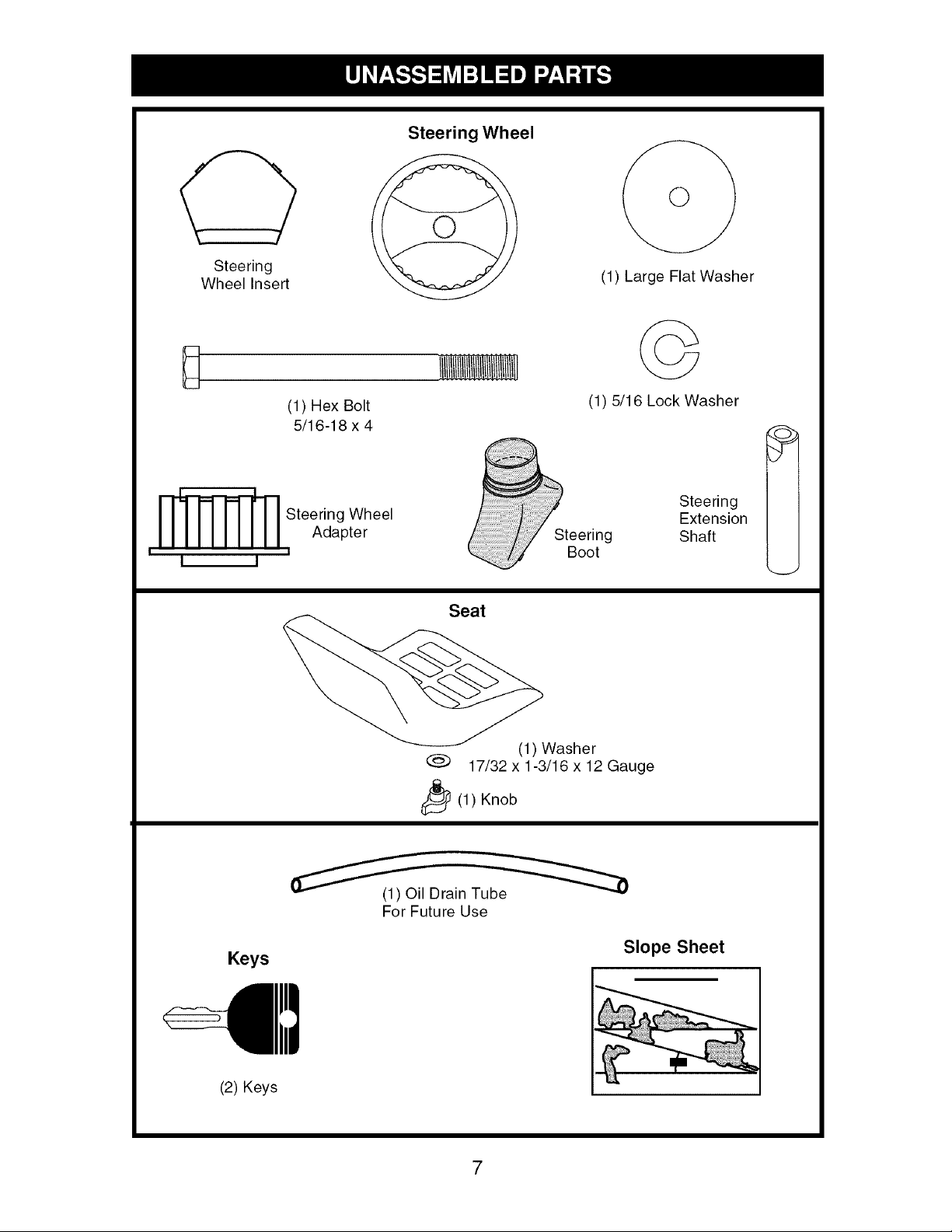
Steering
Wheel Insert
(1) Hex Bolt
5/16-18 x 4
_ Steering Wheel
Adapter
i I I i
Steering Wheel
@
(1) Large Flat Washer
©
(1) 5/16 Lock Washer
Boot
Steering
Extension
Shaft
Seat
(1) Washer
@ 17/32 x1-3/16 x12 Gauge
_(1 ) Knob
Keys
(1) Oil Drain Tube
For Future Use
Slope Sheet
(2) Keys
7
Your new tractor has been assembled at the factory with the exception of those parts left
unassembled for shipping purposes. To ensure safe and proper operation of your tractor
all parts and hardware you assemble must be tightened securely. Use the correct tools
as necessary to insure proper tightness.
TOOLS REQUIRED FOR
ASSEMBLY
A socket wrench set will make assembly
easier. Standard wrench sizes you need
are listed below.
(1) 3/4" wrench (1) Pliers
(1) 1/2" wrench (1) Utility knife
(1) Tire pressure gauge
When right or left hand is mentioned in
this manual, it means when you are in
the operating position (seated behind the
steering wheel).
TO REMOVE TRACTOR FROM
CARTON
UNPACK CARTON
1. Remove all accessible loose parts and
parts boxes from carton.
2. Cut along dashed lines on all four pan-
els of carton. Remove end panels and
lay side panels flat.
3. Check for any additional loose parts or
cartons and remove.
BEFORE REMOVING TRACTOR
FROM SKID
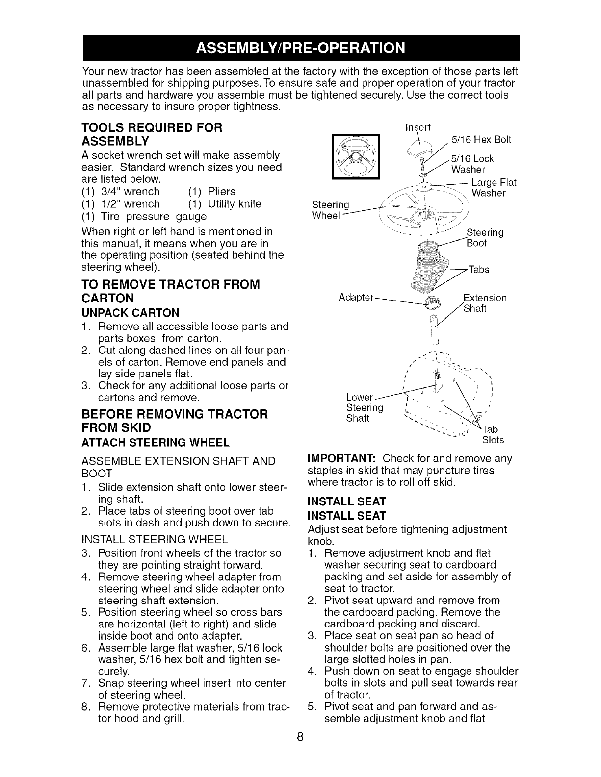
ATTACH STEERING WHEEL
ASSEMBLE EXTENSION SHAFT AND
BOOT
1. Slide extension shaft onto lower steer-
ing shaft.
2. Place tabs of steering boot over tab
slots in dash and push down to secure.
INSTALL STEERING WHEEL
3. Position front wheels of the tractor so
they are pointing straight forward.
4. Remove steering wheel adapter from
steering wheel and slide adapter onto
steering shaft extension.
5. Position steering wheel so cross bars
are horizontal (left to right) and slide
inside boot and onto adapter.
6. Assemble large flat washer, 5/16 lock
washer, 5/16 hex bolt and tighten se-
curely.
7. Snap steering wheel insert into center
of steering wheel.
8. Remove protective materials from trac-
tor hood and grill.
/-%\1
!i ilii
Steering
Wheel
Insert
5/16 Hex Bolt
Steering
IMPORTANT: Check for and remove any
staples in skid that may puncture tires
where tractor is to roll off skid.
INSTALL SEAT
INSTALL SEAT
Adjust seat before tightening adjustment
knob.
1. Remove adjustment knob and flat
washer securing seat to cardboard
packing and set aside for assembly of
seat to tractor.
2. Pivot seat upward and remove from
the cardboard packing. Remove the
cardboard packing and discard.
3. Place seat on seat pan so head of
shoulder bolts are positioned over the
large slotted holes in pan.
4. Push down on seat to engage shoulder
bolts in slots and pull seat towards rear
of tractor.
5. Pivot seat and pan forward and as-
semble adjustment knob and flat
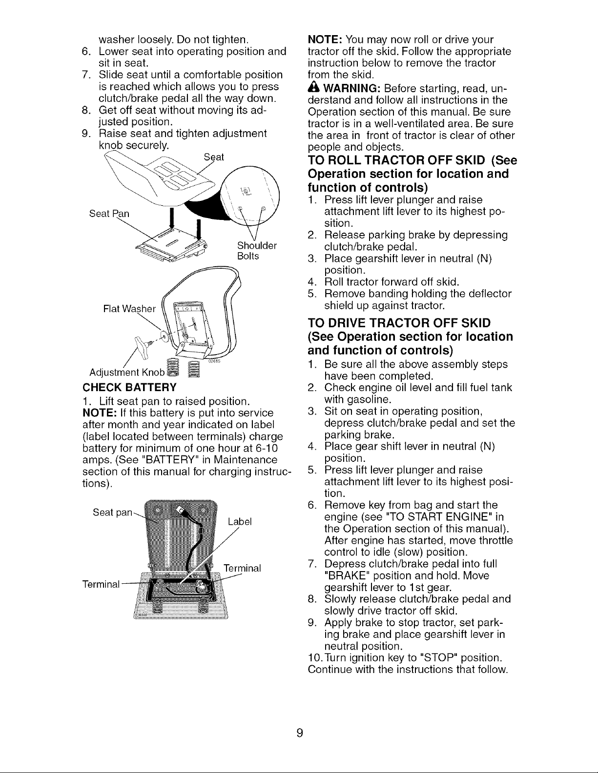
washerloosely.Do not tighten.
6. Lowerseat into operatingpositionand
sit in seat.
7. Slideseat until a comfortableposition
is reachedwhich allowsyou to press
clutch/brakepedal all the way down.
8. Get off seat withoutmoving its ad-
justed position.
9. Raiseseat and tightenadjustment
knob securely.
Seat
Seat Pa_
Shoulder
Bolts
Flat Washer
Adjustment Knob
CHECK BATTERY
1. Lift seat pan to raised position.
NOTE: If this battery is put into service
after month and year indicated on label
(label located between terminals) charge
battery for minimum of one hour at 6-10
amps. (See "BATTERY" in Maintenance
section of this manual for charging instruc-
tions).
Seat
Label
Terminal
NOTE: You may now roll or drive your
tractor off the skid. Follow the appropriate
instruction below to remove the tractor
from the skid.
WARNING: Before starting, read, un-
derstand and follow all instructions in the
Operation section of this manual. Be sure
tractor is in a well-ventilated area. Be sure
the area in front of tractor is clear of other
people and objects.
TO ROLL TRACTOR OFF SKID (See
Operation section for location and
function of controls)
1. Press lift lever plunger and raise
attachment lift lever to its highest po-
sition.
2. Release parking brake by depressing
clutch/brake pedal.
3. Place gearshift lever in neutral (N)
position.
4. Roll tractor forward off skid.
5. Remove banding holding the deflector
shield up against tractor.
TO DRIVE TRACTOR OFF SKID
(See Operation section for location
and function of controls)
1. Be sure all the above assembly steps
have been completed.
2. Check engine oil level and fill fuel tank
with gasoline.
3. Sit on seat in operating position,
depress clutch/brake pedal and set the
parking brake.
4. Place gear shift lever in neutral (N)
position.
5. Press lift lever plunger and raise
attachment lift lever to its highest posi-
tion.
6. Remove key from bag and start the
engine (see "TO START ENGINE" in
the Operation section of this manual).
After engine has started, move throttle
control to idle (slow) position.
7. Depress clutch/brake pedal into full
"BRAKE" position and hold. Move
gearshift lever to 1st gear.
8. Slowly release clutch/brake pedal and
slowly drive tractor off skid.
9. Apply brake to stop tractor, set park-
ing brake and place gearshift lever in
neutral position.
10.Turn ignition key to "STOP" position.
Continue with the instructions that follow.
9
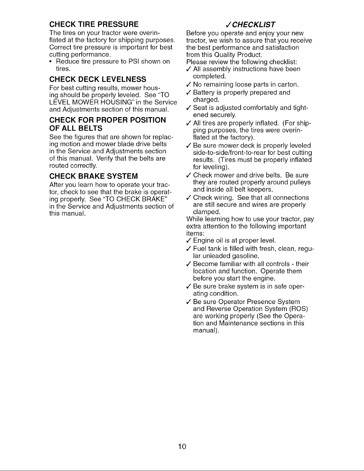
CHECK TIRE PRESSURE
The tires on your tractor were overin-
flated at the factory for shipping purposes.
Correct tire pressure is important for best
cutting performance.
• Reduce tire pressure to PSI shown on
tires.
CHECK DECK LEVELNESS
For best cutting results, mower hous-
ing should be properly leveled. See "TO
LEVEL MOWER HOUSING" in the Service
and Adjustments section of this manual.
CHECK FOR PROPER POSITION
OF ALL BELTS
See the figures that are shown for replac-
ing motion and mower blade drive belts
in the Service and Adjustments section
of this manual. Verify that the belts are
routed correctly.
CHECK BRAKE SYSTEM
After you learn how to operate your trac-
tor, check to see that the brake is operat-
ing properly. See "TO CHECK BRAKE"
in the Service and Adjustments section of
this manual.
#" CHECKLIST
Before you operate and enjoy your new
tractor, we wish to assure that you receive
the best performance and satisfaction
from this Quality Product.
Please review the following checklist:
,/All assembly instructions have been
completed.
,/No remaining loose parts in carton.
,/Battery is properly prepared and
charged.
,/Seat is adjusted comfortably and tight-
ened securely.
,/All tires are properly inflated. (For ship-
ping purposes, the tires were overin-
flated at the factory).
,/Be sure mower deck is properly leveled
side-to-side/front-to-rear for best cutting
results. (Tires must be properly inflated
for leveling).
,/Check mower and drive belts. Be sure
they are routed properly around pulleys
and inside all belt keepers.
,/Check wiring. See that all connections
are still secure and wires are properly
clamped.
While learning how to use your tractor, pay
extra attention to the following important
items:
,/Engine oil is at proper level.
,/Fuel tank is filled with fresh, clean, regu-
lar unleaded gasoline.
,/Become familiar with all controls - their
location and function. Operate them
before you start the engine.
,/Be sure brake system is in safe oper-
ating condition.
,/Be sure Operator Presence System
and Reverse Operation System (ROS)
are working properly (See the Opera-
tion and Maintenance sections in this
manual).
10
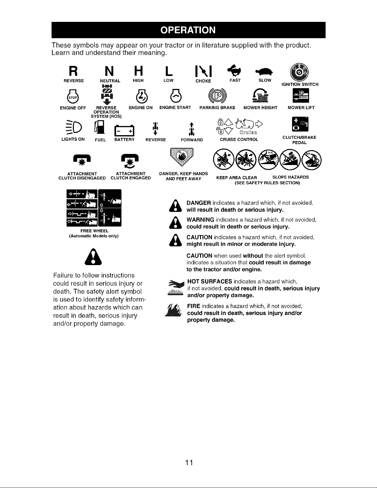
These symbols may appear on your tractor or in literature supplied with the product.
Learn and understand their meaning.
R N H I\1
REVERSE NEUTRAL HIGH LOW CHOKE FAST SLOW
ENGINE OFF REVERSE ENGINE ON ENGINE START PARKING BRAKE MOWER HEIGHT
OPERATION
SYSTEM (ROS)
LIGHTS ON
FUEL BATTERY REVERSE FORWARD CRUISE CONTROL
ATTACHMENT ATTACHMENT
CLUTCH DISENGAGED CLUTCH ENGAGED
IGNITION SWITCH
MOWER LIFT
FREE WHEEL
(Automatic Models only)
DANGER, KEEP HANDS
AND FEET AWAY
CLUTCH/BRAKE
PEDAL
KEEP AREA CLEAR SLOPE HAZARDS
(SEE SAFETY RULES SECTION)
&
Failure to follow instructions
could result in serious injury or
death. The safety alert symbol
is used to identify safety inform-
ation about hazards which can
result in death, serious injury
and/or property damage.
DANGER indicates a hazard which, if not avoided,
will result in death or serious injury.
WARNING indicates a hazard which, if not avoided,
could result in death or serious injury.
CAUTION indicates a hazard which, if not avoided,
might result in minor or moderate injury.
,Jl_l{_l/l£111.,
CAUTION when used without the alert symbol,
indicates a situation that could result in damage
to the tractor and/or engine.
HOT SURFACES indicates a hazard which,
if not avoided, could result in death, serious injury
and/or property damage.
FIRE indicates a hazard which, if not avoided,
could result in death, serious injury and/or
property damage.
11
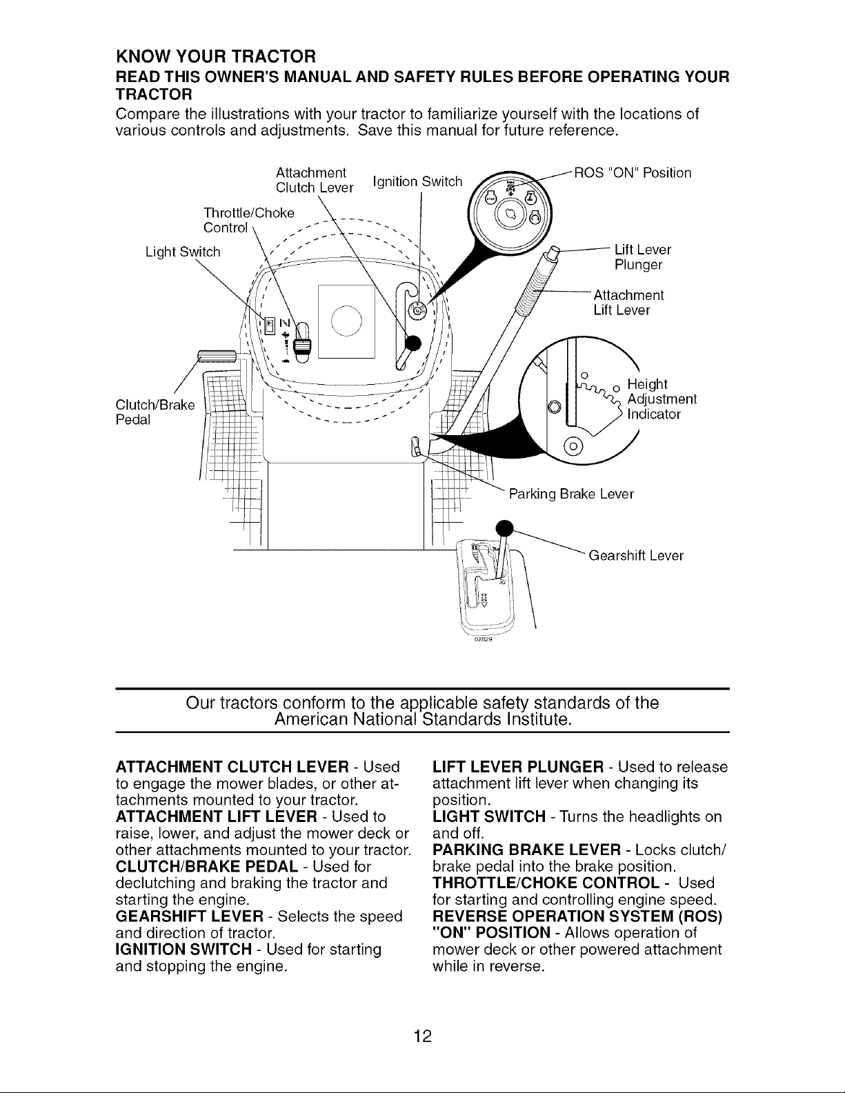
KNOW YOUR TRACTOR
READ THIS OWNER'S MANUAL AND SAFETY RULES BEFORE OPERATING YOUR
TRACTOR
Compare the illustrations with your tractor to familiarize yourself with the locations of
various controls and adjustments. Save this manual for future reference.
Attachment
Clutch Lever
Throttle/Choke
Control
Light Switch
Ignition Switch
Clutch/Brake
Pedal
"
"ON" Position
/q
Lift Lever
Plunger
Attachment
Lift Lever
_nC_ ight
ustment
icator
Parking Brake Lever
Gearshift Lever
Our tractors conform to the applicable safety standards of the
American National Standards Institute.
ATTACHMENT CLUTCH LEVER - Used
to engage the mower blades, or other at-
tachments mounted to your tractor.
ATTACHMENT LIFT LEVER - Used to
raise, lower, and adjust the mower deck or
other attachments mounted to your tractor.
CLUTCH/BRAKE PEDAL - Used for
declutching and braking the tractor and
starting the engine.
GEARSHIFT LEVER - Selects the speed
and direction of tractor.
IGNITION SWITCH - Used for starting
and stopping the engine.
LIFT LEVER PLUNGER - Used to release
attachment lift lever when changing its
position.
LIGHT SWITCH - Turns the headlights on
and off.
PARKING BRAKE LEVER - Locks clutch/
brake pedal into the brake position.
THROTTLE/CHOKE CONTROL - Used
for starting and controlling engine speed.
REVERSE OPERATION SYSTEM (ROS)
"ON" POSITION - Allows operation of
mower deck or other powered attachment
while in reverse.
12
The operation of any tractor can result in foreign objects thrown into
the eyes, which can result in severe eye damage. Always wear safety
glasses or eye shields while operating your tractor or performing any
adjustments or repairs. We recommend a wide vision safety mask over
spectacles or standard safety glasses.
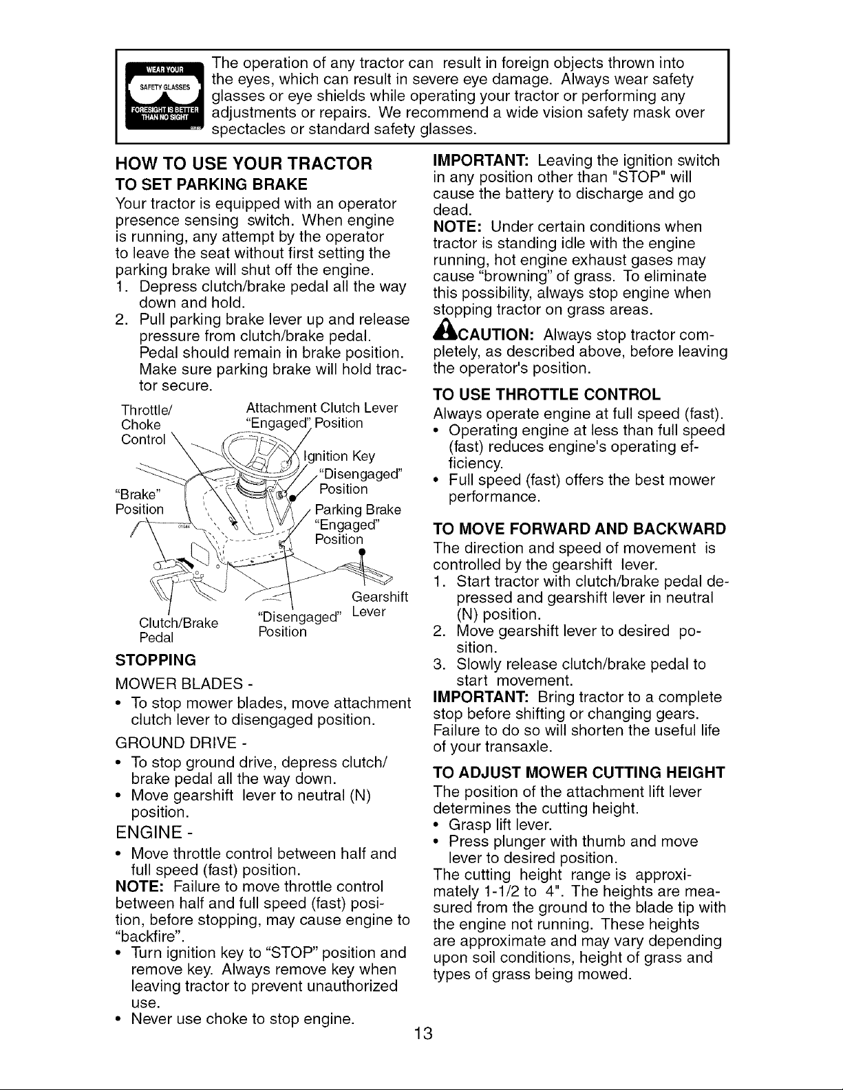
HOW TO USE YOUR TRACTOR
TO SET PARKING BRAKE
Your tractor is equipped with an operator
presence sensing switch. When engine
is running, any attempt by the operator
to leave the seat without first setting the
parking brake will shut off the engine.
1. Depress clutch/brake pedal all the way
down and hold.
2. Pull parking brake lever up and release
pressure from clutch/brake pedal.
Pedal should remain in brake position.
Make sure parking brake will hold trac-
tor secure.
Throttle/ Attachment Clutch Lever
Choke "Enc Position
Control _
nition Key
,"Disengaged"
Position
"Brake"
Position
Parking Brake
"Engaged"
Position
Gearshift
Clutch/Brake "Disengaged" Lever
Pedal Position
STOPPING
MOWER BLADES -
• To stop mower blades, move attachment
clutch lever to disengaged position.
GROUND DRIVE -
• To stop ground drive, depress clutch/
brake pedal all the way down.
• Move gearshift lever to neutral (N)
position.
ENGINE -
• Move throttle control between half and
full speed (fast) position.
NOTE: Failure to move throttle control
between half and full speed (fast) posi-
tion, before stopping, may cause engine to
"backfire".
• Turn ignition key to "STOP" position and
remove key. Always remove key when
leaving tractor to prevent unauthorized
use.
• Never use choke to stop engine.
IMPORTANT: Leaving the ignition switch
in any position other than "STOP" will
cause the battery to discharge and go
dead.
NOTE: Under certain conditions when
tractor is standing idle with the engine
running, hot engine exhaust gases may
cause "browning" of grass. To eliminate
this possibility, always stop engine when
stopping tractor on grass areas.
_CAUTION: Always stop tractor com-
pletely, as described above, before leaving
the operator's position.
TO USE THROTTLE CONTROL
Always operate engine at full speed (fast).
• Operating engine at less than full speed
(fast) reduces engine's operating ef-
ficiency.
• Full speed (fast) offers the best mower
performance.
TO MOVE FORWARD AND BACKWARD
The direction and speed of movement is
controlled by the gearshift lever.
1. Start tractor with clutch/brake pedal de-
pressed and gearshift lever in neutral
(N) position.
2. Move gearshift lever to desired po-
sition.
3. Slowly release clutch/brake pedal to
start movement.
IMPORTANT: Bring tractor to a complete
stop before shifting or changing gears.
Failure to do so will shorten the useful life
of your transaxle.
TO ADJUST MOWER CUTTING HEIGHT
The position of the attachment lift lever
determines the cutting height.
• Grasp lift lever.
• Press plunger with thumb and move
lever to desired position.
The cutting height range is approxi-
mately 1-1/2 to 4". The heights are mea-
sured from the ground to the blade tip with
the engine not running. These heights
are approximate and may vary depending
upon soil conditions, height of grass and
types of grass being mowed.
13
• The average lawn should be cut to ap-
proximately 2-1/2 inches during the cool
season and to over 3 inches during hot
months. For healthier and better looking
lawns, mow often and after moderate
growth.
• For best cutting performance, grass over
6 inches in height should be mowed
twice. Make the first cut relatively high;
the second to desired height.
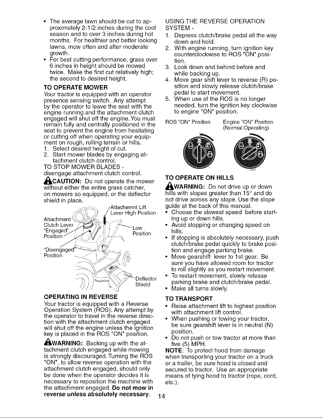
TO OPERATE MOWER
Your tractor is equipped with an operator
presence sensing switch. Any attempt
by the operator to leave the seat with the
engine running and the attachment clutch
engaged will shut off the engine. You must
remain fully and centrally positioned in the
seat to prevent the engine from hesitating
or cutting off when operating your equip-
ment on rough, rolling terrain or hills.
1. Select desired height of cut.
2. Start mower blades by engaging at-
tachment clutch control.
TO STOP MOWER BLADES -
disengage attachment clutch control.
_ICAUTION: Do not operate the mower
without either the entire grass catcher,
on mowers so equipped, or the deflector
shield in place.
Lift
Lever High Position
Attachment ___,,_,
Clutch Lever ,4,_--..._Low
"En(
Position Position
Shield
OPERATING IN REVERSE
Your tractor is equipped with a Reverse
Operation System (ROS). Any attempt by
the operator to travel in the reverse direc-
tion with the attachment clutch engaged
will shut off the engine unless the ignition
key is placed in the ROS "ON" position.
,d_,WARNING: Backing up with the at-
tachment clutch engaged while mowing
is strongly discouraged. Turning the ROS
"ON", to allow reverse operation with the
attachment clutch engaged, should only
be done when the operator decides it is
necessary to reposition the machine with
the attachment engaged. Do not mow in
reverse unless absolutely necessary.
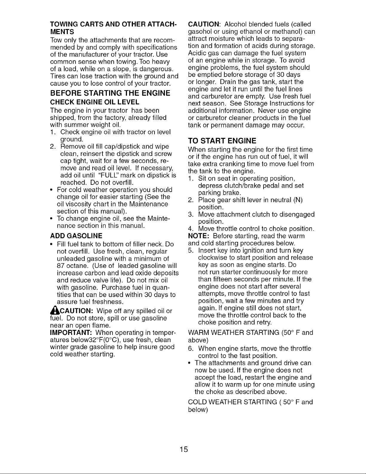
USING THE REVERSE OPERATION
SYSTEM -
1. Depress clutch/brake pedal all the way
down and hold.
2. With engine running, turn ignition key
counterclockwise to ROS "ON" posi-
tion.
3. Look down and behind before and
while backing up.
4. Move gear shift lever to reverse (R) po-
sition and slowly release clutch/brake
pedal to start movement.
5. When use of the ROS is no longer
needed, turn the ignition key clockwise
to engine "ON" position.
ROS "ON" Position
Engine "ON" Position
(Normal Operating)
TO OPERATE ON HILLS
,_WARNING: Do not drive up or down
hills with slopes greater than 15 ° and do
not drive across any slope. Use the slope
guide at the back of this manual.
• Choose the slowest speed before start-
ing up or down hills.
• Avoid stopping or changing speed on
hills.
• If stopping is absolutely necessary, push
clutch/brake pedal quickly to brake posi-
tion and engage parking brake.
• Move gearshift lever to 1st gear. Be
sure you have allowed room for tractor
to roll slightly as you restart movement.
• To restart movement, slowly release
parking brake and clutch/brake pedal.
• Make all turns slowly.
TO TRANSPORT
• Raise attachment lift to highest position
with attachment lift control.
• When pushing or towing your tractor,
be sure gearshift lever is in neutral (N)
position.
• Do not push or tow tractor at more than
five (5) MPH.
NOTE: To protect hood from damage
when transporting your tractor on a truck
or a trailer, be sure hood is closed and
secured to tractor. Use an appropriate
means of tying hood to tractor (rope, cord,
etc.).
14
TOWING CARTS AND OTHER ATTACH-
MENTS
Tow only the attachments that are recom-
mended by and comply with specifications
of the manufacturer of your tractor. Use
common sense when towing. Too heavy
of a load, while on a slope, is dangerous.
Tires can lose traction with the ground and
cause you to lose control of your tractor.
BEFORE STARTING THE ENGINE
CHECK ENGINE OIL LEVEL
The engine in your tractor has been
shipped, from the factory, already filled
with summer weight oil.
1. Check engine oil with tractor on level
ground.
2. Remove oil fill cap/dipstick and wipe
clean, reinsert the dipstick and screw
cap tight, wait for a few seconds, re-
move and read oil level. If necessary,
add oil until "FULl" mark on dipstick is
reached. Do not overfill.
• For cold weather operation you should
change oil for easier starting (See the
oil viscosity chart in the Maintenance
section of this manual).
• To change engine oil, see the Mainte-
nance section in this manual.
ADD GASOLINE
• Fill fuel tank to bottom of filler neck. Do
not overfill. Use fresh, clean, regular
unleaded gasoline with a minimum of
87 octane. (Use of leaded gasoline will
increase carbon and lead oxide deposits
and reduce valve life). Do not mix oil
with gasoline. Purchase fuel in quan-
tities that can be used within 30 days to
assure fuel freshness.
_CAUTION: Wipe off any spilled oil or
fuel. Do not store, spill or use gasoline
near an open flame.
IMPORTANT: When operating in temper-
atures below32°F(0°C), use fresh, clean
winter grade gasoline to help insure good
cold weather starting.
CAUTION: Alcohol blended fuels (called
gasohol or using ethanol or methanol) can
attract moisture which leads to separa-
tion and formation of acids during storage.
Acidic gas can damage the fuel system
of an engine while in storage. To avoid
engine problems, the fuel system should
be emptied before storage of 30 days
or longer. Drain the gas tank, start the
engine and let it run until the fuel lines
and carburetor are empty. Use fresh fuel
next season. See Storage Instructions for
additional information. Never use engine
or carburetor cleaner products in the fuel
tank or permanent damage may occur.
TO START ENGINE
When starting the engine for the first time
or if the engine has run out of fuel, it will
take extra cranking time to move fuel from
the tank to the engine.
1. Sit on seat in operating position,
depress clutch/brake pedal and set
parking brake.
2. Place gear shift lever in neutral (N)
position.
3. Move attachment clutch to disengaged
position.
4. Move throttle control to choke position.
NOTE: Before starting, read the warm
and cold starting procedures below.
5. Insert key into ignition and turn key
clockwise to start position and release
key as soon as engine starts. Do
not run starter continuously for more
than fifteen seconds per minute. If the
engine does not start after several
attempts, move throttle control to fast
position, wait a few minutes and try
again. If engine still does not start,
move the throttle control back to the
choke position and retry.
WARM WEATHER STARTING (50 ° F and
above)
6. When engine starts, move the throttle
control to the fast position.
• The attachments and ground drive can
now be used. If the engine does not
accept the load, restart the engine and
allow it to warm up for one minute using
the choke as described above.
COLD WEATHER STARTING ( 50 ° F and
below)
15
6. When engine starts, leave throttle
control in choke position until engine
warms up and begins to run roughly.
Once rough running begins, imme-
diately move the throttle control to the
fast position. Engine warm-up may
take from several seconds to several
minutes (the colder the temperature,
the longer the warm-up).
• The attachments can also be used dur-
ing the engine warm-up period.
NOTE: If at a high altitude (above 3000
feet) or in cold temperatures (below 32 F)
the carburetor fuel mixture may need to
be adjusted for best engine performance
(see "TO ADJUST CARBURETOR" in the
Service and Adjustments section of this
manual).
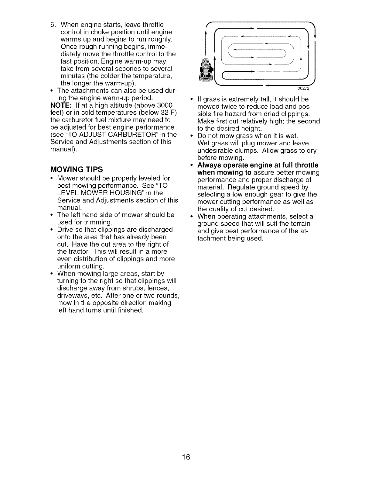
MOWING TIPS
• Mower should be properly leveled for
best mowing performance. See "TO
LEVEL MOWER HOUSING" in the
Service and Adjustments section of this
manual.
• The left hand side of mower should be
used for trimming.
• Drive so that clippings are discharged
onto the area that has already been
cut. Have the cut area to the right of
the tractor. This will result in a more
even distribution of clippings and more
uniform cutting.
• When mowing large areas, start by
turning to the right so that clippings will
discharge away from shrubs, fences,
driveways, etc. After one or two rounds,
mow in the opposite direction making
left hand turns until finished.
(
J
00272
• If grass is extremely tall, it should be
mowed twice to reduce load and pos-
sible fire hazard from dried clippings.
Make first cut relatively high; the second
to the desired height.
• Do not mow grass when it is wet.
Wet grass will plug mower and leave
undesirable clumps. Allow grass to dry
before mowing.
• Always operate engine at full throttle
when mowing to assure better mowing
performance and proper discharge of
material. Regulate ground speed by
selecting a low enough gear to give the
mower cutting performance as well as
the quality of cut desired.
• When operating attachments, select a
ground speed that will suit the terrain
and give best performance of the at-
tachment being used.
16
BEFORE EVERY EVERY EVERY EVERY EVERY BEFORE
EACH 8 25 50 100 SEASON STORAGE
USE HOURS HOURS HOURS HOURS
MAINTENANCE
SCHEDULE
2,heck Brake Operation
2,heck Tire Pressure
T
R 2,heck Operator Presence & ROS Systern_
A Dheck for Loose Fasteners
C Dheck/Replace Mower Blades
t _ubrication Chart
0 Dheck Battery Level
R Dlean Battery and Terminals
Dheck Transaxle Cooling
Dheck Mower Levelness
2,heck V-Belts
Dheck Engine Oil Level
._hange Engine Oil (with oil filter)
Change Engine Oil (without oil filter
_ 2,lean Air Filter
G 3lean Air Screen
I nspect Muffler/Spark Arrester
N _eplace Oil Filter (If equipped)
E 3lean Engine Cooling Fins
_eplace Spark Plug
qeplace Air Filter Paper Cartridge
__ R_._olace Fuel Filter
_2
V
v"
1 - Change more often when operating under a heavy load or
in high ambient temperatures.
2 - Service more often when operating in dirty or dusty conditions.
3 - Replace blades more often when mowing in sandy soil,
4 - Not required if equipped with maintenance-tree battery,
GENERAL RECOMMENDATIONS
The warranty on this tractor does not
cover items that have been subjected to Q S_
operator abuse or negligence. To receive Zerk
full value from the warranty, operator
must maintain tractor as instructed in this
manual.
Some adjustments will need to be made
periodically to properly maintain your
tractor.
At least once a season, check to see if
you should make any of the adjustments @Engine
described in the Service and Adjustments "
section of this manual. "
• At least once a year you should replace
the spark plug, clean or replace air filter,
and check blades and belts for wear.
A new spark plug and clean air filter
assure proper air-fuel mixture and help
your engine run better and last longer.
BEFORE EACH USE
1. Check engine oil level.
2. Check brake operation.
3. Check tire pressure.
4. Check operator presence and
ROS systems for proper operation.
5. Check for loose fasteners.
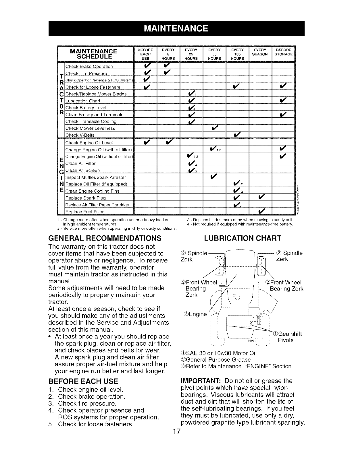
LUBRICATION CHART
-- @ Spindle
Zerk
@Front Wheel ,-
Bearing
Zerk
@Front Wheel
Bearing Zerk
_SAE 30 or 10w30 Motor Oil
@General Purpose Grease
_PRefer to Maintenance "ENGINE" Section
IMPORTANT: Do not oil or grease the
pivot points which have special nylon
bearings. Viscous lubricants will attract
dust and dirt that will shorten the life of
the self-lubricating bearings. If you feel
they must be lubricated, use only a dry,
powdered graphite type lubricant sparingly.
17
TRACTOR
Alwaysobservesafety ruleswhen per-
forming any maintenance.
BRAKE OPERATION
If tractor requiresmore than five (5) feetto
stopat highest speedin highestgear on a
level,dry concreteor paved surface,then
brakemust be checkedand adjusted.(See
"TOADJUSTBRAKE"in the Serviceand
Adjustmentssection of this manual).
TIRES
• Maintainproper air pressurein all tires
(See "PRODUCTSPECIFICATIONS"
sectionof this manual).
• Keeptires free of gasoline,oil, or insect
controlchemicalswhichcan harm rub-
ber.
• Avoidstumps,stones,deep ruts, sharp
objectsand other hazardsthat may
causetire damage.
NOTE:Toseal tire puncturesand prevent
flat tires due to slow leaks,tire sealant
maybe purchasedfrom your local parts
dealer.Tire sealantalso preventstire dry
rot and corrosion.
OPERATORPRESENCESYSTEMAND
REVERSEOPERATIONSYSTEM(ROS)
Besure operatorpresenceand reverse
operationsystemsare working properly. If
your tractor does not functionas de-
scribed,repairthe problemimmediately.
• The engine should not start unless the
brake pedal is fully depressed, and the
attachment clutch control is in the disen-
gaged position.
CHECK OPERATOR PRESENCE
SYSTEM
• When the engine is running, any at-
tempt by the operator to leave the seat
without first setting the parking brake
should shut off the engine.
• When the engine is running and the
attachment clutch is engaged, any at-
tempt by the operator to leave the seat
should shut off the engine.
• The attachment clutch should never op-
erate unless the operator is in the seat.
CHECK REVERSE OPERATION (ROS)
SYSTEM
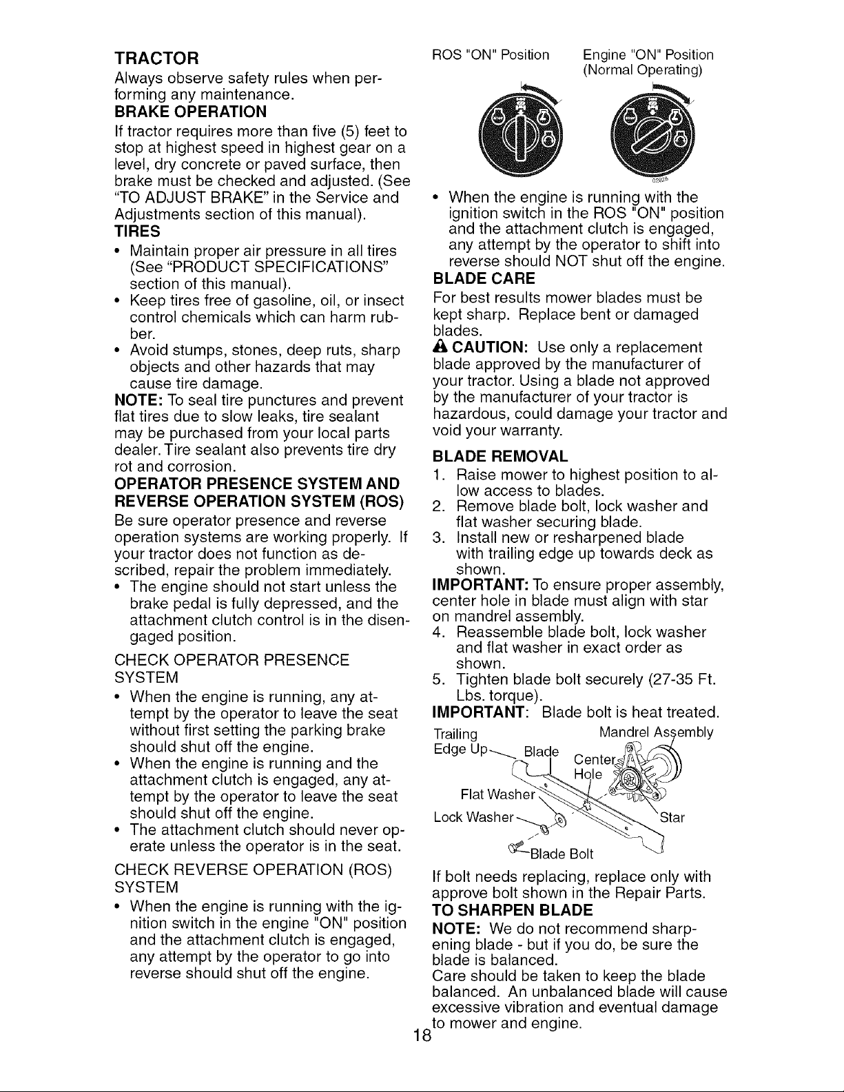
• When the engine is running with the ig-
nition switch in the engine "ON" position
and the attachment clutch is engaged,
any attempt by the operator to go into
reverse should shut off the engine.
ROS "ON" Position
Engine "ON" Position
(Normal Operating)
• When the engine is running with the
ignition switch in the ROS "ON" position
and the attachment clutch is engaged,
any attempt by the operator to shift into
reverse should NOT shut off the engine.
BLADE CARE
For best results mower blades must be
kept sharp. Replace bent or damaged
blades.
CAUTION: Use only a replacement
blade approved by the manufacturer of
your tractor. Using a blade not approved
by the manufacturer of your tractor is
hazardous, could damage your tractor and
void your warranty.
BLADE REMOVAL
1. Raise mower to highest position to al-
low access to blades.
2. Remove blade bolt, lock washer and
flat washer securing blade.
3. Install new or resharpened blade
with trailing edge up towards deck as
shown.
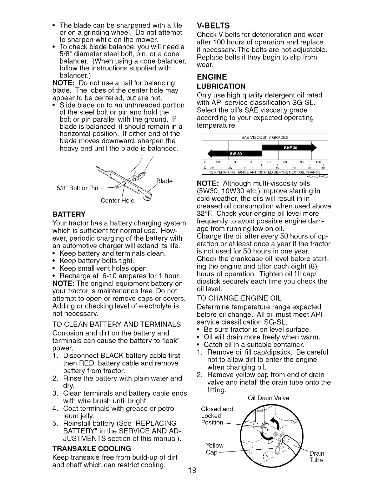
IMPORTANT: To ensure proper assembly,
center hole in blade must align with star
on mandrel assembly.
4. Reassemble blade bolt, lock washer
and flat washer in exact order as
shown.
5. Tighten blade bolt securely (27-35 Ft.
Lbs. torque).
IMPORTANT: Blade bolt is heat treated.
Trailing Mandrel As,,
Edge Up_ Blade
Centel
Hole
Lock Washer
_--Blade Bolt
If bolt needs replacing, replace only with
approve bolt shown in the Repair Parts.
TO SHARPEN BLADE
NOTE: We do not recommend sharp-
ening blade - but if you do, be sure the
blade is balanced.
Care should be taken to keep the blade
balanced. An unbalanced blade will cause
excessive vibration and eventual damage
to mower and engine.
18
• The bladecan be sharpenedwith a file
or on a grindingwheel. Do not attempt
to sharpenwhile on the mower.
• Tocheck blade balance,you will need a
5/8" diametersteel bolt, pin, or a cone
balancer. (Whenusing a conebalancer,
followthe instructionssuppliedwith
balancer.)
NOTE: Do not use a nail for balancing
blade. The lobes of the center hole may
appearto be centered,butare not.
• Slide bladeon to an unthreadedportion
of the steel bolt or pin and hold the
bolt or pin parallelwith the ground. If
blade is balanced,it should remainin a
horizontalposition. If either end of the
blade movesdownward,sharpenthe
heavyend untilthe blade is balanced.
5/8" Bolt or Pin
Blade
Center Hole
BATTERY
Your tractor has a battery charging system
which is sufficient for normal use. How-
ever, periodic charging of the battery with
an automotive charger will extend its life.
• Keep battery and terminals clean.
• Keep battery bolts tight.
• Keep small vent holes open.
• Recharge at 6-10 amperes for 1 hour.
NOTE: The original equipment battery on
your tractor is maintenance free. Do not
attempt to open or remove caps or covers.
Adding or checking level of electrolyte is
not necessary.
TO CLEAN BATTERY AND TERMINALS
Corrosion and dirt on the battery and
terminals can cause the battery to "leak"
power.
1. Disconnect BLACK battery cable first
then RED battery cable and remove
battery from tractor.
2. Rinse the battery with plain water and
dry.
3. Clean terminals and battery cable ends
with wire brush until bright.
4. Coat terminals with grease or petro-
leum jelly.
5. Reinstall battery (See "REPLACING
BATTERY" in the SERVICE AND AD-
JUSTMENTS section of this manual).
TRANSAXLE COOLING
Keep transaxle free from build-up of dirt
and chaff which can restrict cooling.
V-BELTS
Check V-belts for deterioration and wear
after 100 hours of operation and replace
if necessary. The belts are not adjustable.
Replace belts if they begin to slip from
wear.
ENGINE
LUBRICATION
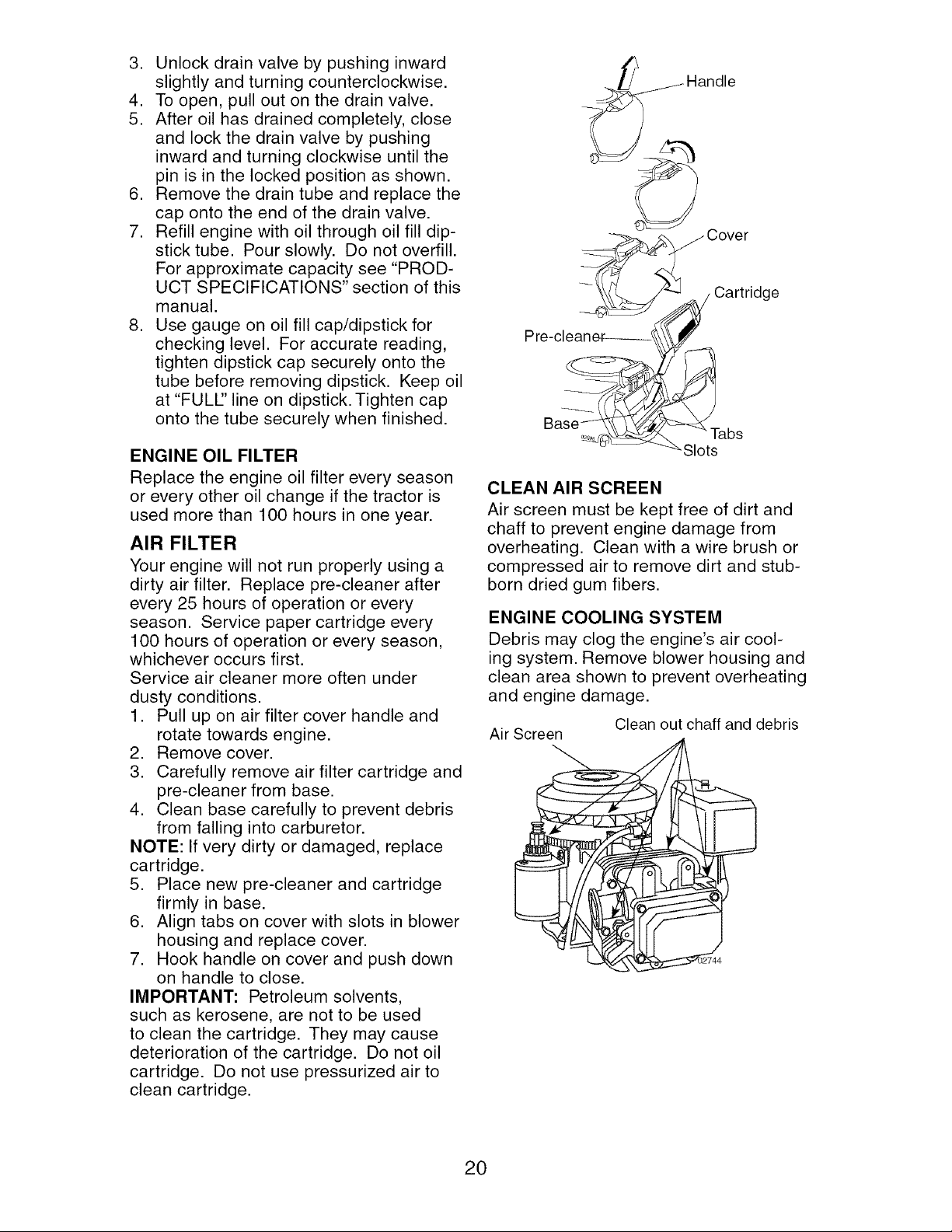
Only use high quality detergent oil rated
with API service classification SG-SL.
Select the oil's SAE viscosity grade
according to your expected operating
temperature.
SAE VISCOSITY GRADES
-30 -20 -10 0 20 30 40
TEMPERATURE RANGE ANTICIPATED BEFORE NEXT OIL CHANGE
oi]vJs¢ chair1 e
NOTE: Although multi-viscosity oils
(5W30, 10W30 etc.)improve starting in
cold weather, the oils will result in in-
creased oil consumption when used above
32°R Check your engine oil level more
frequently to avoid possible engine dam-
age from running low on oil.
Change the oil after every 50 hours of op-
eration or at least once a year if the tractor
is not used for 50 hours in one year.
Check the crankcase oil level before start-
ing the engine and after each eight (8)
hours of operation. Tighten oil fill cap/
dipstick securely each time you check the
oil level.
TO CHANGE ENGINE OIL
Determine temperature range expected
before oil change. All oil must meet API
service classification SG-SL.
• Be sure tractor is on level surface.
• Oil will drain more freely when warm.
• Catch oil in a suitable container.
1. Remove oil fill cap/dipstick. Be careful
not to allow dirt to enter the engine
when changing oil.
2. Remove yellow cap from end of drain
valve and install the drain tube onto the
fitting.
Oil Drain Valve
19
3. Unlock drain valve by pushing inward
slightly and turning counterclockwise.
4. To open, pull out on the drain valve.
5. After oil has drained completely, close
and lock the drain valve by pushing
inward and turning clockwise until the
pin is in the locked position as shown.
6. Remove the drain tube and replace the
cap onto the end of the drain valve.
7. Refill engine with oil through oil fill dip-
stick tube. Pour slowly. Do not overfill.
For approximate capacity see "PROD-
UCT SPECIFICATIONS" section of this
manual.
8. Use gauge on oil fill cap/dipstick for
checking level. For accurate reading,
tighten dipstick cap securely onto the
tube before removing dipstick. Keep oil
at "FULl" line on dipstick. Tighten cap
onto the tube securely when finished.
ENGINE OIL FILTER
Replace the engine oil filter every season
or every other oil change if the tractor is
used more than 100 hours in one year.
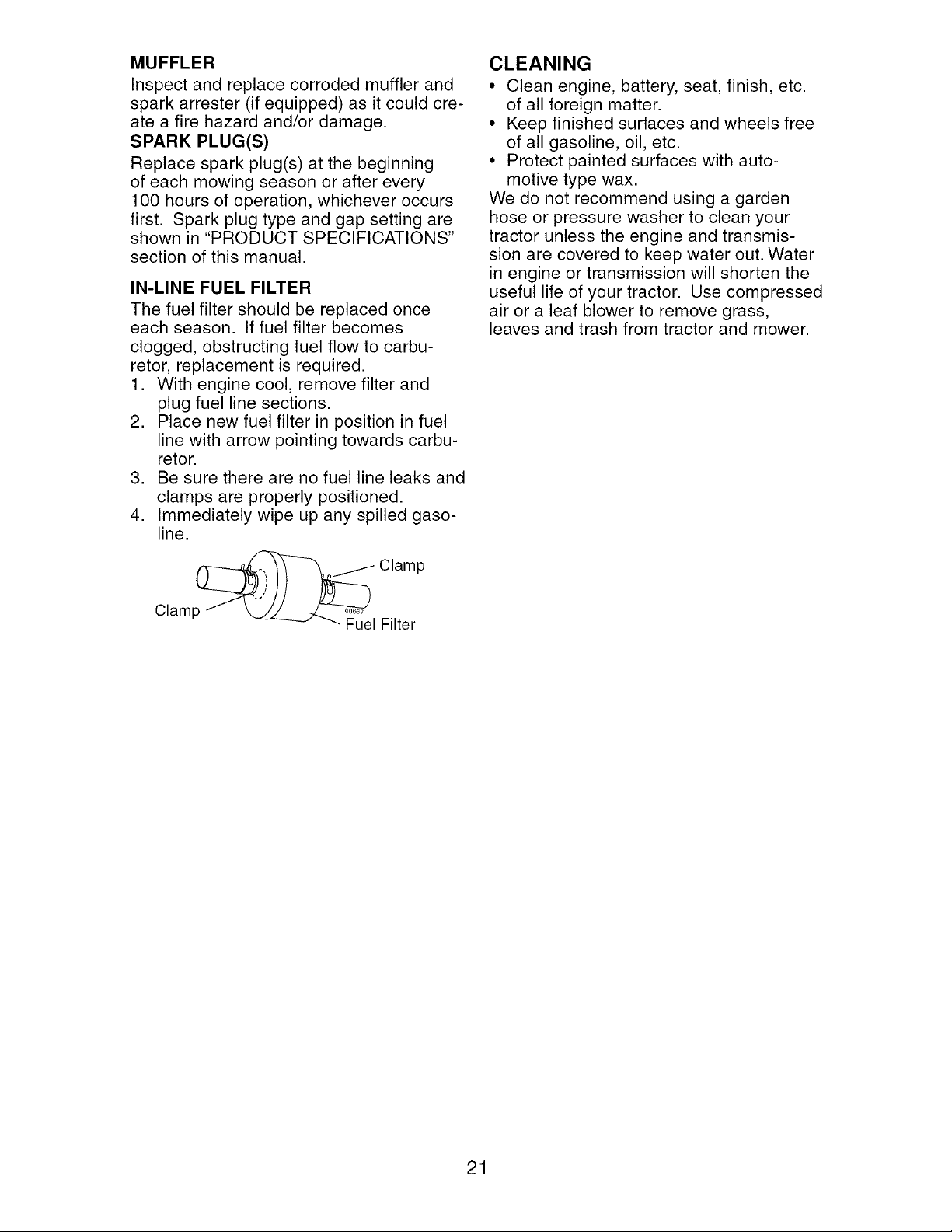
AIR FILTER
Your engine will not run properly using a
dirty air filter. Replace pre-cleaner after
every 25 hours of operation or every
season. Service paper cartridge every
100 hours of operation or every season,
whichever occurs first.
Service air cleaner more often under
dusty conditions.
1. Pull up on air filter cover handle and
rotate towards engine.
2. Remove cover.
3. Carefully remove air filter cartridge and
pre-cleaner from base.
4. Clean base carefully to prevent debris
from falling into carburetor.
NOTE: If very dirty or damaged, replace
cartridge.
5. Place new pre-cleaner and cartridge
firmly in base.
6. Align tabs on cover with slots in blower
housing and replace cover.
7. Hook handle on cover and push down
on handle to close.
IMPORTANT: Petroleum solvents,
such as kerosene, are not to be used
to clean the cartridge. They may cause
deterioration of the cartridge. Do not oil
cartridge. Do not use pressurized air to
clean cartridge.
Handle
Cartridge
"Slots
CLEAN AIR SCREEN
Air screen must be kept free of dirt and
chaff to prevent engine damage from
overheating. Clean with a wire brush or
compressed air to remove dirt and stub-
born dried gum fibers.
ENGINE COOLING SYSTEM
Debris may clog the engine's air cool-
ing system. Remove blower housing and
clean area shown to prevent overheating
and engine damage.
Air Screen
Clean out chaff and debris
20
MUFFLER
Inspect and replace corroded muffler and
spark arrester (if equipped) as it could cre-
ate a fire hazard and/or damage.
SPARK PLUG(S)
Replace spark plug(s) at the beginning
of each mowing season or after every
100 hours of operation, whichever occurs
first. Spark plug type and gap setting are
shown in "PRODUCT SPECIFICATIONS"
section of this manual.
IN-LINE FUEL FILTER
The fuel filter should be replaced once
each season. If fuel filter becomes
clogged, obstructing fuel flow to carbu-
retor, replacement is required.
1. With engine cool, remove filter and
plug fuel line sections.
2. Place new fuel filter in position in fuel
line with arrow pointing towards carbu-
retor.
3. Be sure there are no fuel line leaks and
clamps are properly positioned.
4. Immediately wipe up any spilled gaso-
line.
Clamp_" Clamp
_ Fuel Filter
CLEANING
• Clean engine, battery, seat, finish, etc.
of all foreign matter.
• Keep finished surfaces and wheels free
of all gasoline, oil, etc.
• Protect painted surfaces with auto-
motive type wax.
We do not recommend using a garden
hose or pressure washer to clean your
tractor unless the engine and transmis-
sion are covered to keep water out. Water
in engine or transmission will shorten the
useful life of your tractor. Use compressed
air or a leaf blower to remove grass,
leaves and trash from tractor and mower.
21
&
WARNING: TO AVOID SERIOUS INJURY, BEFORE PERFORMING ANY
SERVICE OR ADJUSTMENTS:
1. Depress clutch/brake pedal fully and set parking brake.
2. Place gearshift lever in neutral (N) position.
3. Place attachment clutch in "DISENGAGED" position.
4. Turn ignition key to "STOP" and remove key.
5. Make sure the blades and all moving parts have completely stopped.
6. Disconnect spark plug wire from spark plug and place wire where it cannot
come in contact with plug.
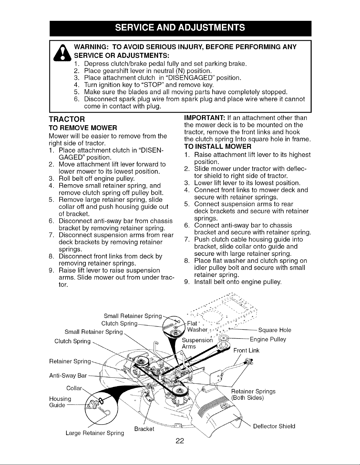
TRACTOR
TO REMOVE MOWER
Mower will be easier to remove from the
right side of tractor.
1. Place attachment clutch in "DISEN-
GAGED" position.
2. Move attachment lift lever forward to
lower mower to its lowest position.
3. Roll belt off engine pulley.
4. Remove small retainer spring, and
remove clutch spring off pulley bolt.
5. Remove large retainer spring, slide
collar off and push housing guide out
of bracket.
6. Disconnect anti-sway bar from chassis
bracket by removing retainer spring.
7. Disconnect suspension arms from rear
deck brackets by removing retainer
springs.
8. Disconnect front links from deck by
removing retainer springs.
9. Raise lift lever to raise suspension
arms. Slide mower out from under trac-
tor.
IMPORTANT: If an attachment other than
the mower deck is to be mounted on the
tractor, remove the front links and hook
the clutch spring Into square hole in frame.
TO INSTALL MOWER
1. Raise attachment lift lever to its highest
position.
2. Slide mower under tractor with deflec-
tor shield to right side of tractor.
3. Lower lift lever to its lowest position.
4. Connect front links to mower deck and
secure with retainer springs.
5. Connect suspension arms to rear
deck brackets and secure with retainer
springs.
6. Connect anti-sway bar to chassis
bracket and secure with retainer spring.
7. Push clutch cable housing guide into
bracket, slide collar onto guide and
secure with large retainer spring.
8. Place flat washer and clutch spring on
idler pulley bolt and secure with small
retainer spring.
9. Install belt onto engine pulley.
Small
Clutch Spring
Small
Clutch
Front Link
Retainer S
Anti-Sway Bar
Housing
Guide --
Large Retainer Spring
Bracket
22
Retainer Springs
Both Sides)
Deflector Shield
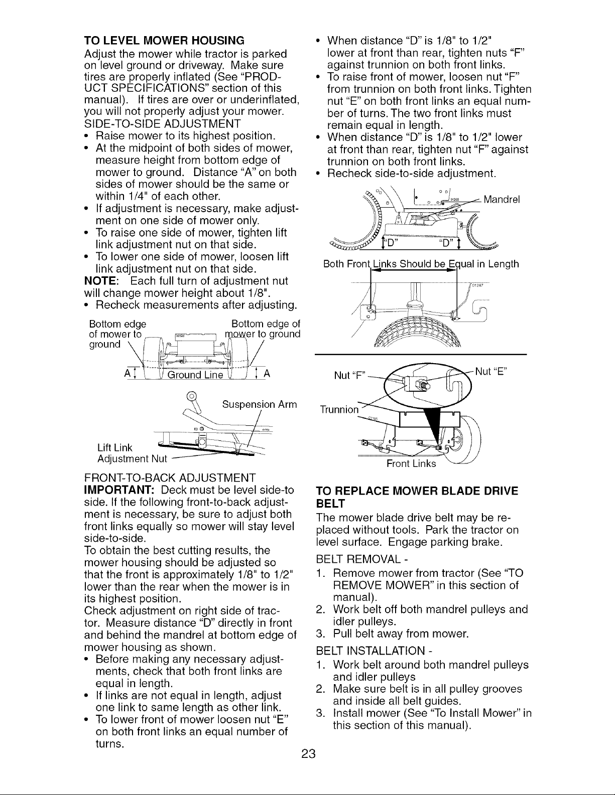
TO LEVEL MOWER HOUSING
Adjust the mower while tractor is parked
on level ground or driveway. Make sure
tires are properly inflated (See "PROD-
UCT SPECIFICATIONS" section of this
manual). If tires are over or underinflated,
you will not properly adjust your mower.
SIDE-TO-SIDE ADJUSTMENT
• Raise mower to its highest position.
• At the midpoint of both sides of mower,
measure height from bottom edge of
mower to ground. Distance "A" on both
sides of mower should be the same or
within 1/4" of each other.
• If adjustment is necessary, make adjust-
ment on one side of mower only.
• To raise one side of mower, tighten lift
link adjustment nut on that side.
• To lower one side of mower, loosen lift
link adjustment nut on that side.
NOTE: Each full turn of adjustment nut
will change mower height about 1/8".
• Recheck measurements after adjusting.
Bottom edge Bottom edge of
of mower to r--_ _n3-o_,er to ground
\I L--V__]-J ; A
• When distance "D" is 1/8" to 1/2"
lower at front than rear, tighten nuts "F"
against trunnion on both front links.
• To raise front of mower, loosen nut "F"
from trunnion on both front links. Tighten
nut "E" on both front links an equal num-
ber of turns. The two front links must
remain equal in length.
• When distance "D" is 1/8" to 1/2" lower
at front than rear, tighten nut "F" against
trunnion on both front links.
• Recheck side-to-side adjustment.
°°o °°.... Mandrel
Both Front Unks Should beEqual in Length
..............................
Nut
_E _
Arm
Lift Link N_
Adjustment
FRONT-TO-BACK ADJUSTMENT
IMPORTANT: Deck must be level side-to
side. If the following front-to-back adjust-
ment is necessary, be sure to adjust both
front links equally so mower will stay level
side-to-side.
To obtain the best cutting results, the
mower housing should be adjusted so
that the front is approximately 1/8" to 1/2"
lower than the rear when the mower is in
its highest position.
Check adjustment on right side of trac-
tor. Measure distance "D" directly in front
and behind the mandrel at bottom edge of
mower housing as shown.
• Before making any necessary adjust-
ments, check that both front links are
equal in length.
• If links are not equal in length, adjust
one link to same length as other link.
• To lower front of mower loosen nut "E"
on both front links an equal number of
turns.
Trunnion
Front Links
TO REPLACE MOWER BLADE DRIVE
BELT
The mower blade drive belt may be re-
placed without tools. Park the tractor on
level surface. Engage parking brake.
BELT REMOVAL -
1. Remove mower from tractor (See "TO
REMOVE MOWER" in this section of
manual).
2. Work belt off both mandrel pulleys and
idler pulleys.
3. Pull belt away from mower.
BELT INSTALLATION -
1. Work belt around both mandrel pulleys
and idler pulleys
2. Make sure belt is in all pulley grooves
and inside all belt guides.
3. Install mower (See "To Install Mower" in
this section of this manual).
23
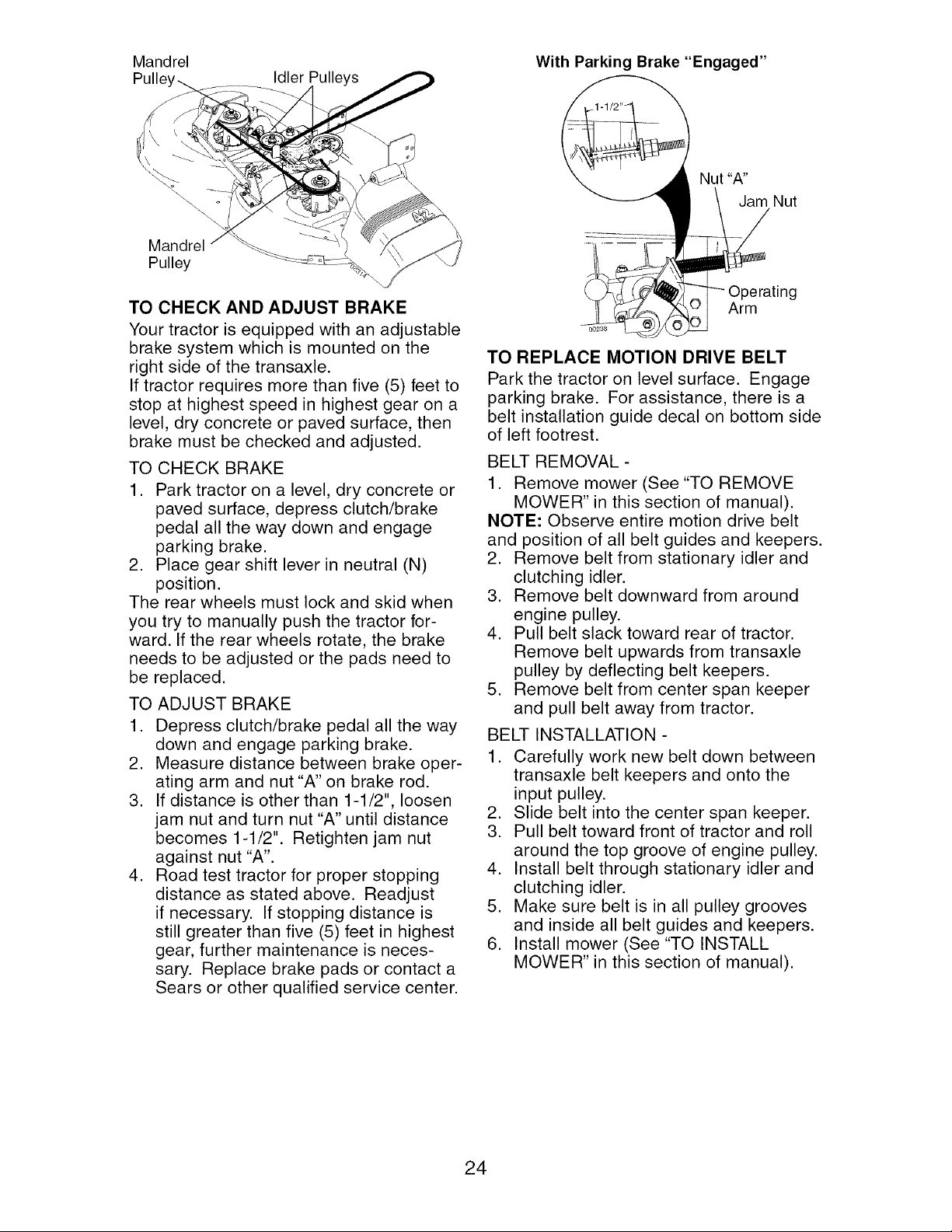
Mandrel With Parking Brake "Engaged"
Idler Pulleys
Nut "A"
Jam Nut
Mandrel
Pulley
TO CHECK AND ADJUST BRAKE
Your tractor is equipped with an adjustable
brake system which is mounted on the
right side of the transaxle.
If tractor requires more than five (5) feet to
stop at highest speed in highest gear on a
level, dry concrete or paved surface, then
brake must be checked and adjusted.
TO CHECK BRAKE
1. Park tractor on a level, dry concrete or
paved surface, depress clutch/brake
pedal all the way down and engage
parking brake.
2. Place gear shift lever in neutral (N)
position.
The rear wheels must lock and skid when
you try to manually push the tractor for-
ward. If the rear wheels rotate, the brake
needs to be adjusted or the pads need to
be replaced.
TO ADJUST BRAKE
1. Depress clutch/brake pedal all the way
down and engage parking brake.
2. Measure distance between brake oper-
ating arm and nut "A" on brake rod.
3. If distance is other than 1-1/2", loosen
jam nut and turn nut "A" until distance
becomes 1-1/2". Retighten jam nut
against nut "A".
4. Road test tractor for proper stopping
distance as stated above. Readjust
if necessary. If stopping distance is
still greater than five (5) feet in highest
gear, further maintenance is neces-
sary. Replace brake pads or contact a
Sears or other qualified service center.
Operating
Arm
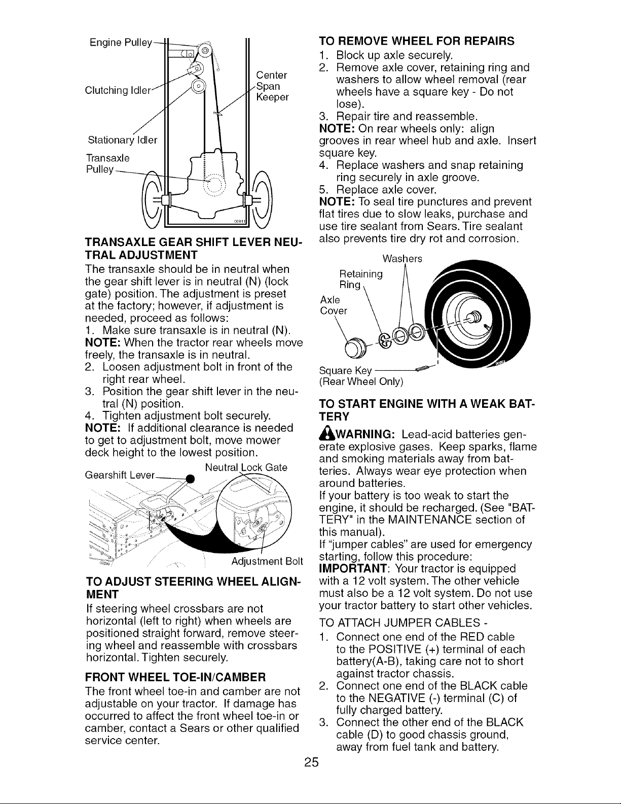
TO REPLACE MOTION DRIVE BELT
Park the tractor on level surface. Engage
parking brake. For assistance, there is a
belt installation guide decal on bottom side
of left footrest.
BELT REMOVAL -
1. Remove mower (See "TO REMOVE
MOWER" in this section of manual).
NOTE: Observe entire motion drive belt
and position of all belt guides and keepers.
2. Remove belt from stationary idler and
clutching idler.
3. Remove belt downward from around
engine pulley.
4. Pull belt slack toward rear of tractor.
Remove belt upwards from transaxle
pulley by deflecting belt keepers.
5. Remove belt from center span keeper
and pull belt away from tractor.
BELT INSTALLATION -
1. Carefully work new belt down between
transaxle belt keepers and onto the
input pulley.
2. Slide belt into the center span keeper.
3. Pull belt toward front of tractor and roll
around the top groove of engine pulley.
4. Install belt through stationary idler and
clutching idler.
5. Make sure belt is in all pulley grooves
and inside all belt guides and keepers.
6. Install mower (See "TO INSTALL
MOWER" in this section of manual).
24
Engine Pulle
Clutching
Center
Keeper
Stationary Idler
Transaxle
TRANSAXLE GEAR SHIFT LEVER NEU-
TRAL ADJUSTMENT
The transaxle should be in neutral when
the gear shift lever is in neutral (N) (lock
gate) position. The adjustment is preset
at the factory; however, if adjustment is
needed, proceed as follows:
1. Make sure transaxle is in neutral (N).
NOTE: When the tractor rear wheels move
freely, the transaxle is in neutral.
2. Loosen adjustment bolt in front of the
right rear wheel.
3. Position the gear shift lever in the neu-
tral (N) position.
4. Tighten adjustment bolt securely.
NOTE: If additional clearance is needed
to get to adjustment bolt, move mower
deck height to the lowest position.
Neutral Lock Gate
Gearshift
.....,,.... Adjustment Bolt
TO ADJUST STEERING WHEEL ALIGN-
MENT
If steering wheel crossbars are not
horizontal (left to right) when wheels are
positioned straight forward, remove steer-
ing wheel and reassemble with crossbars
horizontal. Tighten securely.
FRONT WHEEL TOE-IN/CAMBER
The front wheel toe-in and camber are not
adjustable on your tractor. If damage has
occurred to affect the front wheel toe-in or
camber, contact a Sears or other qualified
service center.
TO REMOVE WHEEL FOR REPAIRS
1. Block up axle securely.
2. Remove axle cover, retaining ring and
washers to allow wheel removal (rear
wheels have a square key - Do not
lose).
3. Repair tire and reassemble.
NOTE: On rear wheels only: align
grooves in rear wheel hub and axle. Insert
square key.
4. Replace washers and snap retaining
ring securely in axle groove.
5. Replace axle cover.
NOTE: To seal tire punctures and prevent
flat tires due to slow leaks, purchase and
use tire sealant from Sears. Tire sealant
also prevents tire dry rot and corrosion.
Washers
Retaining
Ring
Axle
Cover
I
Square Key
(Rear Wheel Only)
TO START ENGINE WITH A WEAK BAT-
TERY
_,WARNING: Lead-acid batteries gen-
erate explosive gases. Keep sparks, flame
and smoking materials away from bat-
teries. Always wear eye protection when
around batteries.
If your battery is too weak to start the
engine, it should be recharged. (See "BAT-
TERY" in the MAINTENANCE section of
this manual).
If "jumper cables" are used for emergency
starting, follow this procedure:
IMPORTANT: Your tractor is equipped
with a 12 volt system. The other vehicle
must also be a 12 volt system. Do not use
your tractor battery to start other vehicles.
TO ATTACH JUMPER CABLES -
1. Connect one end of the RED cable
to the POSITIVE (+) terminal of each
battery(A-B), taking care not to short
against tractor chassis.
2. Connect one end of the BLACK cable
to the NEGATIVE (-) terminal (C) of
fully charged battery.
3. Connect the other end of the BLACK
cable (D) to good chassis ground,
away from fuel tank and battery.
25
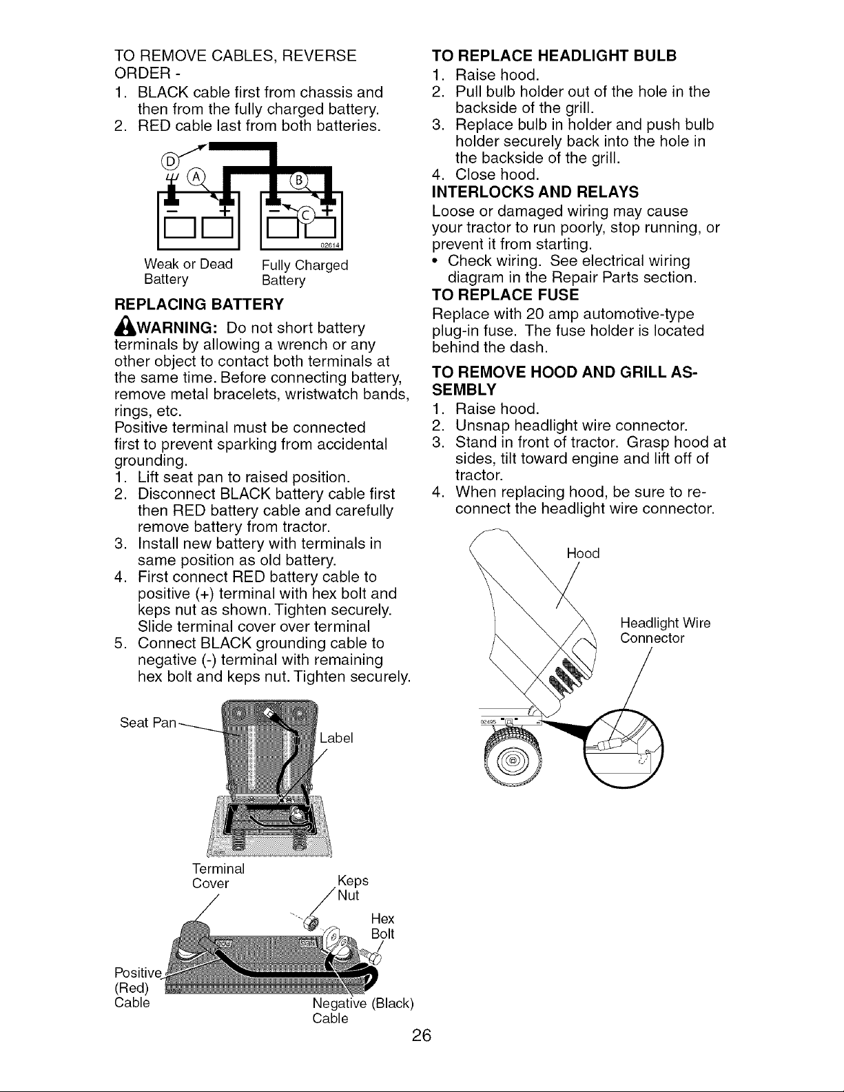
TO REMOVE CABLES, REVERSE
ORDER -
1. BLACK cable first from chassis and
then from the fully charged battery.
2. RED cable last from both batteries.
Weak or Dead Fully Charged
Battery Battery
REPLACING BATTERY
,_WARNING: Do not short battery
terminals by allowing a wrench or any
other object to contact both terminals at
the same time. Before connecting battery,
remove metal bracelets, wristwatch bands,
rings, etc.
Positive terminal must be connected
first to prevent sparking from accidental
grounding.
1. Lift seat pan to raised position.
2. Disconnect BLACK battery cable first
then RED battery cable and carefully
remove battery from tractor.
3. Install new battery with terminals in
same position as old battery.
4. First connect RED battery cable to
positive (+) terminal with hex bolt and
keps nut as shown. Tighten securely.
Slide terminal cover over terminal
5. Connect BLACK grounding cable to
negative (-) terminal with remaining
hex bolt and keps nut. Tighten securely.
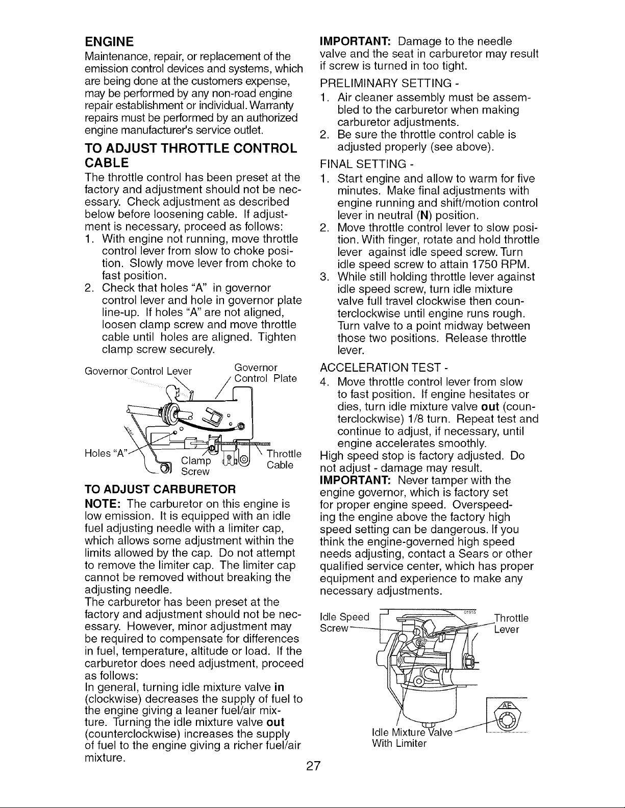
TO REPLACE HEADLIGHT BULB
1. Raise hood.
2. Pull bulb holder out of the hole in the
backside of the grill.
3. Replace bulb in holder and push bulb
holder securely back into the hole in
the backside of the grill.
4. Close hood.
INTERLOCKS AND RELAYS
Loose or damaged wiring may cause
your tractor to run poorly, stop running, or
prevent it from starting.
• Check wiring. See electrical wiring
diagram in the Repair Parts section.
TO REPLACE FUSE
Replace with 20 amp automotive-type
plug-in fuse. The fuse holder is located
behind the dash.
TO REMOVE HOOD AND GRILL AS-
SEMBLY
1. Raise hood.
2. Unsnap headlight wire connector.
3. Stand in front of tractor. Grasp hood at
sides, tilt toward engine and lift off of
tractor.
4. When replacing hood, be sure to re-
connect the headlight wire connector.
Hood
Headlight Wire
Connector
Seat
Label
Terminal
Cover
Keps
Nut
"--_ Hex
Bolt
Positive
(Red)
Cable
Negative (Black)
Cable
26
ENGINE
Maintenance, repair, or replacement of the
emission control devices and systems, which
are being done at the customers expense,
may be performed by any non-road engine
repair establishment or individual. Warranty
repairs must be performed by an authorized
engine manufacturer's service outlet.
TO ADJUST THROTTLE CONTROL
CABLE
The throttle control has been preset at the
factory and adjustment should not be nec-
essary. Check adjustment as described
below before loosening cable. If adjust-
ment is necessary, proceed as follows:
1. With engine not running, move throttle
control lever from slow to choke posi-
tion. Slowly move lever from choke to
fast position.
2. Check that holes "A" in governor
control lever and hole in governor plate
line-up. If holes "A" are not aligned,
loosen clamp screw and move throttle
cable until holes are aligned. Tighten
clamp screw securely.
Governor Control Lever Governor
Plate
(
Holes Throttle
Clamp Cable
Screw
TO ADJUST CARBURETOR
NOTE: The carburetor on this engine is
low emission. It is equipped with an idle
fuel adjusting needle with a limiter cap,
which allows some adjustment within the
limits allowed by the cap. Do not attempt
to remove the limiter cap. The limiter cap
cannot be removed without breaking the
adjusting needle.
The carburetor has been preset at the
factory and adjustment should not be nec-
essary. However, minor adjustment may
be required to compensate for differences
in fuel, temperature, altitude or load. If the
carburetor does need adjustment, proceed
as follows:
In general, turning idle mixture valve in
(clockwise) decreases the supply of fuel to
the engine giving a leaner fuel/air mix-
ture. Turning the idle mixture valve out
(counterclockwise) increases the supply
of fuel to the engine giving a richer fuel/air
mixture.
IMPORTANT: Damage to the needle
valve and the seat in carburetor may result
if screw is turned in too tight.
PRELIMINARY SETTING -
1. Air cleaner assembly must be assem-
bled to the carburetor when making
carburetor adjustments.
2. Be sure the throttle control cable is
adjusted properly (see above).
FINAL SETTING -
1. Start engine and allow to warm for five
minutes. Make final adjustments with
engine running and shift/motion control
lever in neutral (N) position.
2. Move throttle control lever to slow posi-
tion. With finger, rotate and hold throttle
lever against idle speed screw. Turn
idle speed screw to attain 1750 RPM.
3. While still holding throttle lever against
idle speed screw, turn idle mixture
valve full travel clockwise then coun-
terclockwise until engine runs rough.
Turn valve to a point midway between
those two positions. Release throttle
lever.
ACCELERATION TEST -
4. Move throttle control lever from slow
to fast position. If engine hesitates or
dies, turn idle mixture valve out (coun-
terclockwise) 1/8 turn. Repeat test and
continue to adjust, if necessary, until
engine accelerates smoothly.
High speed stop is factory adjusted. Do
not adjust - damage may result.
IMPORTANT: Never tamper with the
engine governor, which is factory set
for proper engine speed. Overspeed-
ing the engine above the factory high
speed setting can be dangerous. If you
think the engine-governed high speed
needs adjusting, contact a Sears or other
qualified service center, which has proper
equipment and experience to make any
necessary adjustments.
Idle Speed F =_ _"-,,._ .... Throttle
Screw--_C _Lever
Idle fixture Valve _
With Limiter
27
Immediately prepare your tractor for stor-
age at the end of the season or if the trac-
tor will not be used for 30 days or more.
_WARNING: Never store the tractor
with gasoline in the tank inside a building
where fumes may reach an open flame
or spark. Allow the engine to cool before
storing in any enclosure.
TRACTOR
Remove mower from tractor for winter
storage. When mower is to be stored for a
period of time, clean it thoroughly, remove
all dirt, grease, leaves, etc. Store in a
clean, dry area.
1. Clean entire tractor (See "CLEANING"
in the Maintenance section of this
manual).
2. Inspect and replace belts, if necessary
(See belt replacement instructions in
the Service and Adjustments section of
this manual).
3. Lubricate as shown in the Maintenance
section of this manual.
4. Be sure that all nuts, bolts and screws
are securely fastened. Inspect moving
parts for damage, breakage and wear.
Replace if necessary.
5. Touch up all rusted or chipped paint
surfaces; sand lightly before painting.
BATTERY
• Fully charge the battery for storage.
• After a period of time in storage, battery
may require recharging.
• To help prevent corrosion and power
leakage during long periods of storage,
battery cables should be disconnected
and battery cleaned thoroughly (see "TO
CLEAN BATTERY AND TERMINALS" in
the Maintenance section of this manual).
• After cleaning, leave cables discon-
nected and place cables where they
cannot come in contact with battery
terminals.
• If battery is removed from tractor for
storage, do not store battery directly on
concrete or damp surfaces.
ENGINE
FUEL SYSTEM
IMPORTANT: It is important to prevent
gum deposits from forming in essential
fuel system parts such as carburetor, fuel
hose, or tank during storage. Also, alcohol
blended fuels (called gasohol or using
ethanol or methanol) can attract moisture
which leads to separation and formation of
acids during storage. Acidic gas can dam-
age the fuel system of an engine while in
storage.
• Empty the fuel tank by starting the en-
gine and letting it run until the fuel lines
and carburetor are empty.
• Never use engine or carburetor cleaner
products in the fuel tank or permanent
damage may occur.
• Use fresh fuel next season.
NOTE: Fuel stabilizer is an acceptable
alternative in minimizing the formation of
fuel gum deposits during storage. Add
stabilizer to gasoline in fuel tank or stor-
age container. Always follow the mix ratio
found on stabilizer container. Run engine
at least 10 minutes after adding stabilizer
to allow the stabilizer to reach the car-
buretor. Do not empty the gas tank and
carburetor if using fuel stabilizer.
ENGINE OIL
Drain oil (with engine warm) and replace
with clean engine oil. (See "ENGINE" in
the Maintenance section of this manual).
CYLINDER(S)
1. Remove spark plug(s).
2. Pour one ounce of oil through spark
plug hole(s) into cylinder(s).
3. Turn ignition key to "START" position
for a few seconds to distribute oil.
4. Replace with new spark plug(s).
OTHER
• Do not store gasoline from one season
to another.
• Replace your gasoline can if your can
starts to rust. Rust and/or dirt in your
gasoline will cause problems.
• If possible, store your tractor indoors
and cover it to give protection from dust
and dirt.
• Cover your tractor with a suitable pro-
tective cover that does not retain mois-
ture. Do not use plastic. Plastic cannot
breathe which allows condensation to
form and will cause your tractor to rust.
IMPORTANT: Never cover tractor while
engine and exhaust areas are still warm.
28
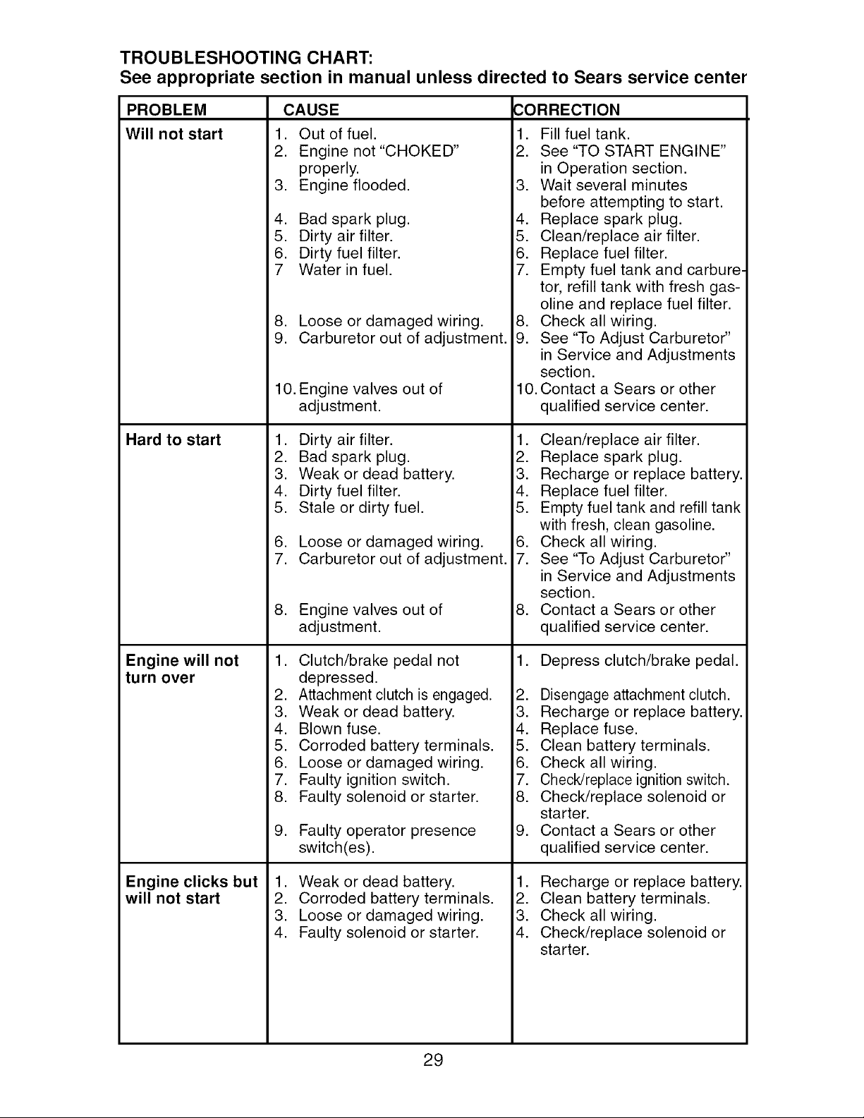
TROUBLESHOOTING CHART:
See appropriate section in manual unless directed to Sears service center
PROBLEM
Will not start
Hard to start
Engine will not
turn over
Engine clicks but
will not start
CAUSE CORRECTION
1. Out of fuel.
2. Engine not "CHOKED"
properly.
3. Engine flooded.
4. Bad spark plug.
5. Dirty air filter.
6. Dirty fuel filter.
7 Water in fuel.
8. Loose or damaged wiring.
9. Carburetor out of adjustment.
10. Engine valves out of
adjustment.
1. Dirty air filter.
2. Bad spark plug.
3. Weak or dead battery.
4. Dirty fuel filter.
5. Stale or dirty fuel.
6. Loose or damaged wiring.
7. Carburetor out of adjustment.
8. Engine valves out of
adjustment.
1. Clutch/brake pedal not
depressed.
2. Attachment clutch is engaged.
3. Weak or dead battery.
4. Blown fuse.
5. Corroded battery terminals.
6. Loose or damaged wiring.
7. Faulty ignition switch.
8. Faulty solenoid or starter.
9. Faulty operator presence
switch(es).
1. Weak or dead battery.
2. Corroded battery terminals.
3. Loose or damaged wiring.
4. Faulty solenoid or starter.
1. Fill fuel tank.
2. See "TO START ENGINE"
in Operation section.
3. Wait several minutes
before attempting to start.
4. Replace spark plug.
5. Clean/replace air filter.
6. Replace fuel filter.
7. Empty fuel tank and carbure-
tor, refill tank with fresh gas-
oline and replace fuel filter.
8. Check all wiring.
9. See "To Adjust Carburetor"
in Service and Adjustments
section.
10. Contact a Sears or other
qualified service center.
1. Clean/replace air filter.
2. Replace spark plug.
3. Recharge or replace battery.
4. Replace fuel filter.
5. Empty fuel tank and refill tank
with fresh, clean gasoline.
6. Check all wiring.
7. See "To Adjust Carburetor"
in Service and Adjustments
section.
8. Contact a Sears or other
qualified service center.
1. Depress clutch/brake pedal.
2. Disengage attachment clutch.
3. Recharge or replace battery.
4. Replace fuse.
5. Clean battery terminals.
6. Check all wiring.
7. Check/replace ignition switch.
8. Check/replace solenoid or
starter.
9. Contact a Sears or other
qualified service center.
1. Recharge or replace battery.
2. Clean battery terminals.
3. Check all wiring.
4. Check/replace solenoid or
starter.
29
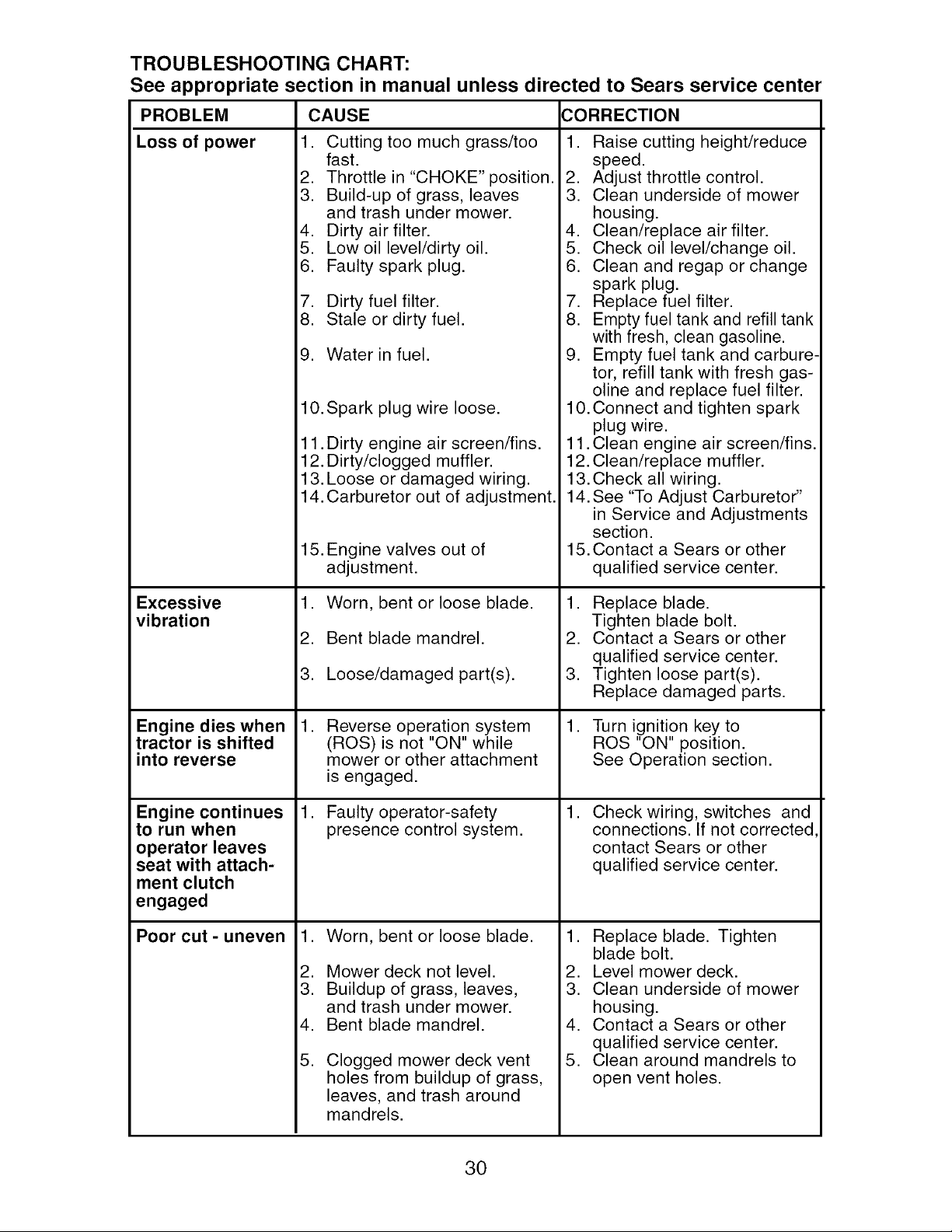
TROUBLESHOOTING CHART:
See appropriate section in manual unless directed to Sears service center
CAUSE CORRECTION
1. Cutting too much grass/too
fast.
2. Throttle in "CHOKE" position.
3. Build-up of grass, leaves
and trash under mower.
4. Dirty air filter.
5. Low oil level/dirty oil.
6. Faulty spark plug.
PROBLEM
Loss of power
Excessive
vibration
Engine dies when
tractor is shifted
into reverse
Engine continues
to run when
operator leaves
seat with attach-
ment clutch
engaged
Poor cut - uneven
7. Dirty fuel filter.
8. Stale or dirty fuel.
9. Water in fuel.
10. Spark plug wire loose.
11. Dirty engine air screen/fins.
12. Dirty/clogged muffler.
13. Loose or damaged wiring.
14. Carburetor out of adjustment.
15. Engine valves out of
adjustment.
1. Worn, bent or loose blade.
2. Bent blade mandrel.
3. Loose/damaged part(s).
,
Reverse operation system
(ROS) is not "ON" while
mower or other attachment
is engaged.
Faulty operator-safety
presence control system.
,
Worn, bent or loose blade.
Mower deck not level.
Buildup of grass, leaves,
and trash under mower.
Bent blade mandrel.
Clogged mower deck vent
holes from buildup of grass,
leaves, and trash around
mandrels.
,
2.
3.
4.
5.
1. Raise cutting height/reduce
speed.
2. Adjust throttle control.
3. Clean underside of mower
housing.
4. Clean/replace air filter.
5. Check oil level/change oil.
6. Clean and regap or change
spark plug.
7. Replace fuel filter.
8. Empty fuel tank and refill tank
with fresh, clean gasoline.
9. Empty fuel tank and carbure-
tor, refill tank with fresh gas-
oline and replace fuel filter.
10. Connect and tighten spark
plug wire.
11. Clean engine air screen/fins.
12. Clean/replace muffler.
13. Check all wiring.
14. See "To Adjust Carburetor"
in Service and Adjustments
section.
15. Contact a Sears or other
qualified service center.
1. Replace blade.
Tighten blade bolt.
2. Contact a Sears or other
qualified service center.
3. Tighten loose part(s).
Replace damaged parts.
1. Turn ignition key to
ROS "ON" position.
See Operation section.
,
Check wiring, switches and
connections. If not corrected
contact Sears or other
qualified service center.
1. Replace blade. Tighten
blade bolt.
2. Level mower deck.
3. Clean underside of mower
housing.
4. Contact a Sears or other
qualified service center.
5. Clean around mandrels to
open vent holes.
30
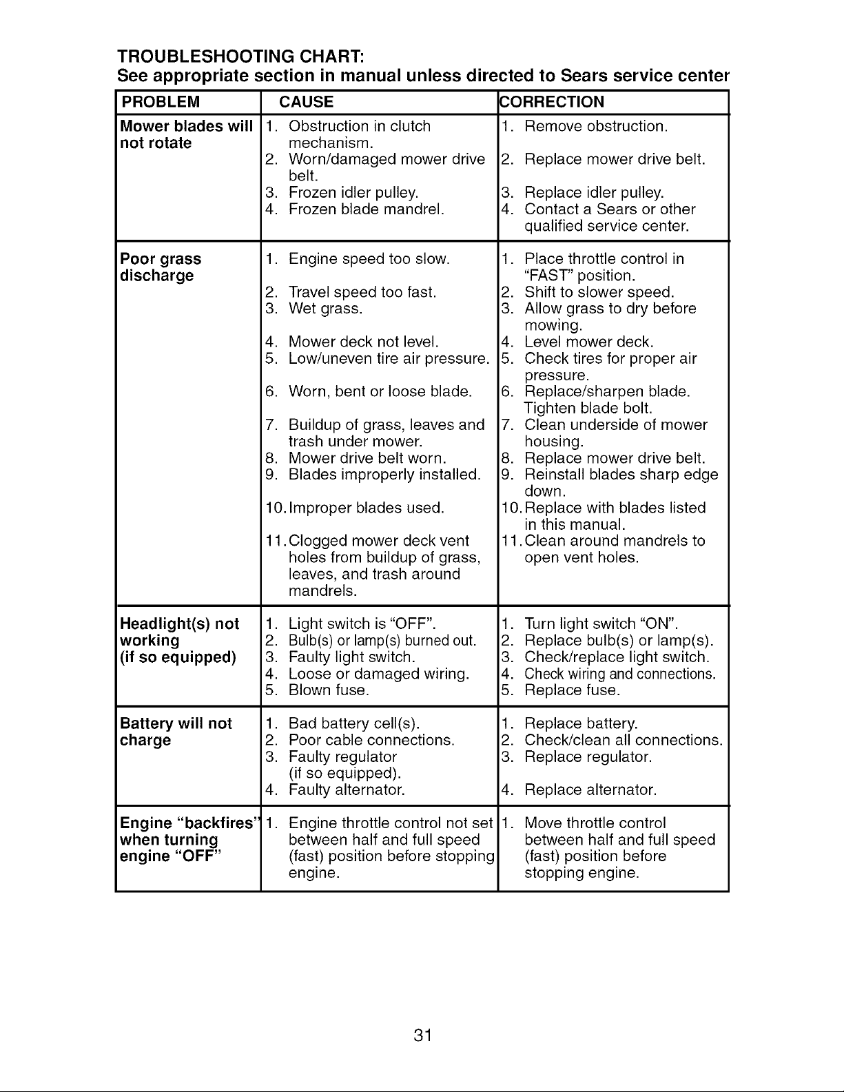
TROUBLESHOOTING CHART:
See appropriate section in manual unless directed to Sears service center
PROBLEM CAUSE CORRECTION
1. Remove obstruction.Mower blades will
not rotate
Poor grass
discharge
Headlight(s) not
working
(if so equipped)
Battery will not
charge
Engine "backfires'
when turning
engine "OFF"
1. Obstruction in clutch
mechanism.
2. Worn/damaged mower drive
belt.
3. Frozen idler pulley.
4. Frozen blade mandrel.
1. Engine speed too slow.
2. Travel speed too fast.
3. Wet grass.
4. Mower deck not level.
5. Low/uneven tire air pressure.
6. Worn, bent or loose blade.
7. Buildup of grass, leaves and
trash under mower.
8. Mower drive belt worn.
9. Blades improperly installed.
10.
11.
Improper blades used.
Clogged mower deck vent
holes from buildup of grass,
leaves, and trash around
mandrels.
1. Light switch is "OFF".
2. Bulb(s) or lamp(s) burned out.
3. Faulty light switch.
4. Loose or damaged wiring.
5. Blown fuse.
1. Bad battery cell(s).
2. Poor cable connections.
3. Faulty regulator
(if so equipped).
4. Faulty alternator.
,
Engine throttle control not set
between half and full speed
(fast) position before stopping
engine.
2. Replace mower drive belt.
3. Replace idler pulley.
4. Contact a Sears or other
qualified service center.
1. Place throttle control in
"FAST" position.
2. Shift to slower speed.
3. Allow grass to dry before
mowing.
4. Level mower deck.
5. Check tires for proper air
pressure.
6. Replace/sharpen blade.
Tighten blade bolt.
7. Clean underside of mower
housing.
8. Replace mower drive belt.
9. Reinstall blades sharp edge
down.
10. Replace with blades listed
in this manual.
11. Clean around mandrels to
open vent holes.
1. Turn light switch "ON".
2. Replace bulb(s) or lamp(s).
3. Check/replace light switch.
4. Check wiring and connections.
5. Replace fuse.
1. Replace battery.
2. Check/clean all connections.
3. Replace regulator.
4. Replace alternator.
, Move throttle control
between half and full speed
(fast) position before
stopping engine.
31

SUGGESTED GUIDE FOR SIGHTING SLOPES FOR SAFE OPERATION
bO
ONLY RIDE UP AND DOWN HILL,
NOT ACROSS HILL
15 DEGREES MAX.
WARNING: To avoid serious injury, operate your tractor up and
down the face of slopes, never across the face. Do not mow
slopes greater than 15 degrees. Make turns gradually to prevent
tipping or loss of control. Exercise extreme caution when
changing direction on slopes.
1. Fold this page along dotted line indicated above.
2. Hold page before you so that its left edge is vertically parallel to a tree
trunk or other upright structure.
3. Sight across the fold in the direction of hill slope you want to measure.
4. Compare the angle of the fold with the slope of the hill.
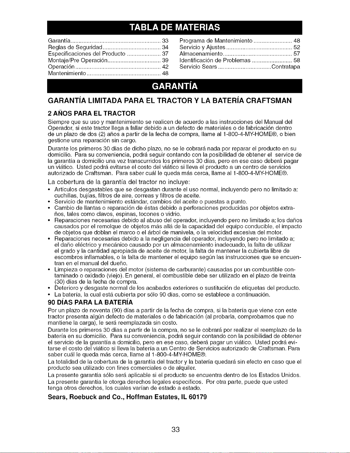
Garantia ........................................................ 33
Reglas de Seguridad .................................... 34
Especificaciones del Producto ..................... 37
Montaje/Pre Operaci6n ................................. 39
Operaci6n ..................................................... 42
Mantenimiento .............................................. 48
Programa de Mantenimiento ........................ 48
Servicio y Ajustes ......................................... 52
Almacenamiento ........................................... 57
Identificaci6n de Problemas ......................... 58
Servicio Sears ................................. Contratapa
GARANTJA LIMITADA PARA EL TRACTOR Y LA BATERJA CRAFTSMAN
2 ANOS PARA EL TRACTOR
Siempre que su uso y mantenimiento se realicen de acuerdo alas instrucciones del Manual del
Operador, si este tractor Ilega a fallar debido a un defecto de materiales o de fabricaci6n dentro
de un plazo de dos (2) aSos a partir de la fecha de compra, Ilame al 1-800-4-MY-HOME®, o bien
gestione una reparaci6n sin cargo.
Durante los primeros 30 dias de dicho plazo, no se le cobrar_, nada por reparar el producto en su
domicilio. Para su conveniencia, podr_t seguir contando con la posibilidad de obtener el service de
la garantia a domicilio una vez transcurridos los primeros 30 dias, pero en ese caso deber_t pagar
un vi_.tico. Usted podr_, evitarse el costo del vi_.tico si Ileva el producto a un centro de servicios
autorizado de Craftsman. Para saber cu_tl le queda m_ts cerca, Ilame al 1-800-4-MY-HOME®.
La cobertura de la garantia del tractor no incluye:
• Articulos desgastables que se desgastan durante el uso normal, incluyendo pero no limitado a:
cuchillas, bujias, filtros de aire, correas y filtros de aceite.
• Servicio de mantenimiento est_.ndar, cambios del aceite o puestas a punto.
• Cambio de Ilantas o reparaci6n de estas debido a perforaciones producidas por objetos extra-
5os, tales como clavos, espinas, tocones o vidrio.
• Reparaciones necesarias debido al abuso del operador, incluyendo pero no limitado a; los dahos
causados por el remolque de objetos m_.s allot de la capacidad del equipo conducible, el impacto
de objetos que doblan el marco o el _.rbol de manivela, o la velocidad excesiva del motor.
• Reparaciones necesarias debido a la negligencia del operador, incluyendo pero no limitado a;
el daSo el6ctrico y mec_.nico causado por un almacenamiento inadecuado, la falta de utilizar
el grado y la cantidad apropiada de aceite de motor, la falta de mantener la cubierta libre de
escombros inflamables, o la falta de mantener el equipo segt3n las instrucciones que se encuen-
tran en el manual del dueSo.
• Limpieza o reparaciones del motor (sistema de carburante) causadas por un combustible con-
taminado o oxidado (viejo). En general, el combustible debe ser utilizado en el plazo de treinta
(30) dias de la fecha de compra.
• Deterioro y desgaste normal de los acabados exteriores o sustituci6n de etiquetas del producto.
• La bateria, la cual est,. cubierta por s61o 90 dias, como se establece a continuaci6n.
90 DJAS PARA LA BATERJA
Por un plazo de noventa (90) dias a partir de la fecha de compra, si la bateria que viene con este
tractor presenta algt_n defecto de materiales o de fabricaci6n (al probarla, comprobamos que no
mantiene la carga), le sera reemplazada sin costo.
Durante los primeros 30 dias a partir de la compra, no se le cobrar_t por realizar el reemplazo de la
bateria en su domicilio. Para su conveniencia, podr_, seguir contando con la posibilidad de obtener
el servicio de la garantia a domicilio, pero en ese caso, deber_, pagar un vi_.tico. Usted podr_, evi-
tarse el costo del vi_ttico si Ileva la bateria a un Centro de Servicios autorizado de Craftsman. Para
saber cual le queda m_.s cerca, Ilame al 1-800-4-MY-HOME®.
La totalidad de la cobertura de la garantia del tractor y la bateria quedara sin efecto en caso que el
producto sea utilizado con fines comerciales o de alquiler.
La presente garantia s61o sera aplicable si el producto se encuentra dentro de los Estados Unidos.
La presente garantia le otorga derechos legales especificos. Por otra parte, puede que usted
tenga otros derechos, los cuales varian de estado a estado.
Sears, Roebuck and Co., Hoffman Estates, IL 60179
33
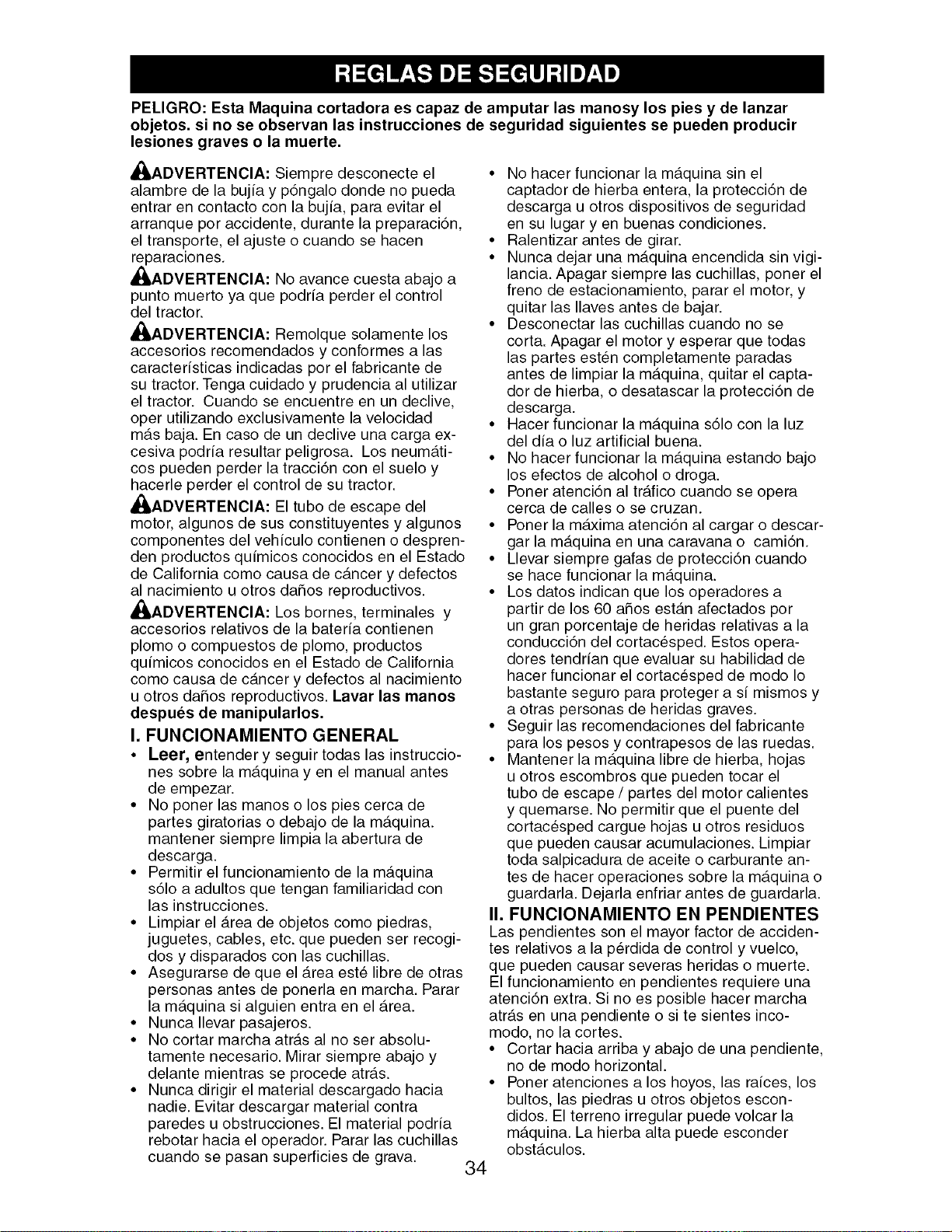
PELIGRO: Esta Maquina cortadora es capaz de amputar las manosy los pies y de lanzar
objetos, si no se observan las instrucciones de seguridad siguientes se pueden producir
lesiones graves o la muerte.
A_,ADVERTENCIA: Siempre desconecte el
alambre de la bujfa y p6ngalo donde no pueda
entrar en contacto con la bujfa, para evitar el
arranque por accidente, durante la preparaci6n,
el transporte, el ajuste o cuando se hacen
reparaciones.
,_ADVERTENClA: No avance cuesta abajo a
punto muerto ya que podrfa perder el control
del tractor.
_IbADVERTENClA: Remolque solamente los
accesorios recomendados y conformes a las
caracterfsticas indicadas por el fabricante de
su tractor. Tenga cuidado y prudencia al utilizar
el tractor. Cuando se encuentre en un declive,
oper utilizando exclusivamente la velocidad
m_.s baja. En caso de un declive una carga ex-
cesiva podrfa resultar peligrosa. Los neum_.ti-
cos pueden perder la tracci6n con el suelo y
hacerle perder el control de su tractor.
_IbADVERTENClA: El tubo de escape del
motor, algunos de sus constituyentes y algunos
componentes del vehfculo contienen o despren-
den productos qufmicos conocidos en el Estado
de California como causa de c_.ncer y defectos
al nacimiento u otros daSos reproductivos.
,_ADVERTENClA: Los bornes, terminales y
accesorios relativos de la baterfa contienen
plomo o compuestos de plomo, productos
qufmicos conocidos en el Estado de California
como causa de c_.ncer y defectos al nacimiento
u otros dafios reproductivos. Lavar las manos
despues de manipularlos.
I. FUNClONAMIENTO GENERAL
• Leer, entender y seguir todas las instruccio-
nes sobre la m_.quina yen el manual antes
de empezar.
• No poner las manos o los pies cerca de
partes giratorias o debajo de la m_.quina.
mantener siempre limpia la abertura de
descarga.
• Permitir el funcionamiento de la m_.quina
s61o a adultos que tengan familiaridad con
las instrucciones.
• Limpiar el _.rea de objetos como piedras,
juguetes, cables, etc. que pueden ser recogi-
dos y disparados con las cuchillas.
• Asegurarse de que el _.rea est_ libre de otras
personas antes de ponerla en marcha. Parar
la m_.quina si alguien entra en el _.rea.
• Nunca Ilevar pasajeros.
• No cortar marcha atr_.s al no ser absolu-
tamente necesario. Mirar siempre abajo y
delante mientras se procede atr_.s.
• Nunca dirigir el material descargado hacia
nadie. Evitar descargar material contra
paredes u obstrucciones. El material podrfa
rebotar hacia el operador. Parar las cuchillas
cuando se pasan superficies de grava.
34
• No hacer funcionar la m_.quina sin el
captador de hierba entera, la protecci6n de
descarga u otros dispositivos de seguridad
en su lugar yen buenas condiciones.
• Ralentizar antes de girar.
• Nunca dejar una m_.quina encendida sin vigi-
lancia. Apagar siempre las cuchillas, poner el
freno de estacionamiento, parar el motor, y
quitar las Ilaves antes de bajar.
• Desconectar las cuchillas cuando no se
corta. Apagar el motor y esperar que todas
las partes esten completamente paradas
antes de limpiar la m_tquina, quitar el capta-
dor de hierba, o desatascar la protecci6n de
descarga.
• Hacer funcionar la m_tquina s61o con la luz
del dia o luz artificial buena.
• No hacer funcionar la m_.quina estando bajo
los efectos de alcohol o droga.
• Poner atenci6n al tr_.fico cuando se opera
cerca de calles o se cruzan.
• Poner la m_.xima atenci6n al cargar o descar-
gar la m_tquina en una caravana o cami6n.
• Llevar siempre gafas de protecci6n cuando
se hace funcionar la m_.quina.
• Los datos indican que los operadores a
partir de los 60 afios est_tn afectados por
un gran porcentaje de heridas relativas a la
conducci6n del cortacesped. Estos opera-
dores tendrian que evaluar su habilidad de
hacer funcionar el cortac_sped de modo Io
bastante seguro para proteger a si mismos y
a otras personas de heridas graves.
• Seguir las recomendaciones del fabricante
para los pesos y contrapesos de las ruedas.
• Mantener la m_.quina libre de hierba, hojas
u otros escombros que pueden tocar el
tubo de escape / partes del motor calientes
y quemarse. No permitir que el puente del
cortacesped cargue hojas u otros residuos
que pueden causar acumulaciones. Limpiar
toda salpicadura de aceite o carburante an-
tes de hacer operaciones sobre la m_.quina o
guardarla. Dejarla enfriar antes de guardarla.
II. FUNClONAMIENTO EN PENDIENTES
Las pendientes son el mayor factor de acciden-
tes relativos a la p_rdida de control y vuelco,
que pueden causar severas heridas o muerte.
El funcionamiento en pendientes requiere una
atenci6n extra. Si no es posible hacer marcha
atr_.s en una pendiente o site sientes inco-
modo, no la cortes.
• Cortar hacia arriba y abajo de una pendiente,
no de modo horizontal.
• Poner atenciones a los hoyos, las raices, los
bultos, las piedras u otros objetos escon-
didos. El terreno irregular puede volcar la
m_.quina. La hierba alta puede esconder
obst_.culos.
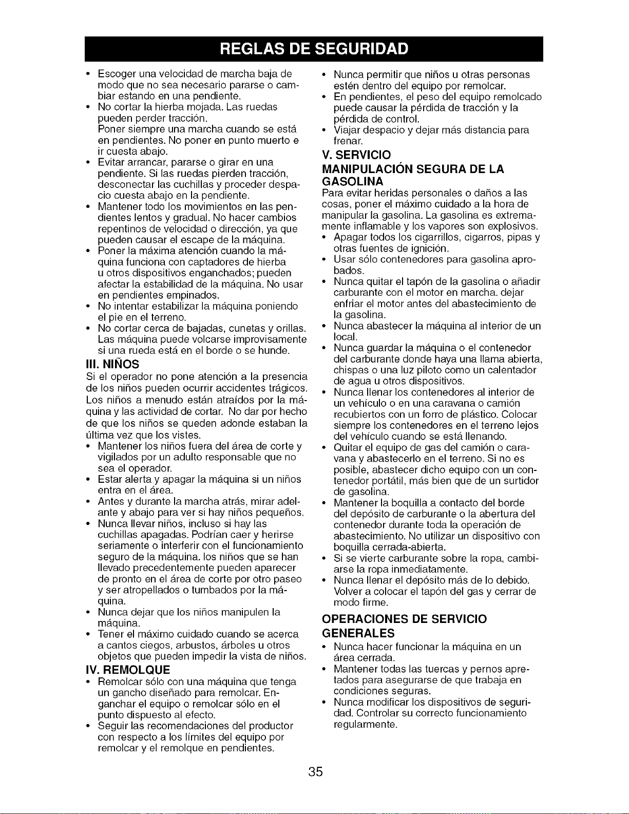
• Escogerunavelocidaddemarchabajade
modoquenoseanecesariopararseo cam-
biarestandoenunapendiente.
• Nocortarla hierbamojada.Lasruedas
puedenperdertracci6n.
Ponersiempreunamarchacuandoseest,.
enpendientes.Noponerenpuntomuertoe
ircuestaabajo.
• Evitararrancar,pararseo girarenuna
pendiente.Silasruedaspierdentracci6n,
desconectarlascuchillasy procederdespa-
ciocuestaabajoenla pendiente.
• Mantenertodolosmovimientosenlaspen-
dienteslentosy gradual.Nohacercambios
repentinosdevelocidado direcci6n,ya que
puedencausarel escapedela m_.quina.
•Poner la m_tximaatenci6ncuandolam_.-
quinafuncionaconcaptadoresdehierba
uotrosdispositivosenganchados;pueden
afectarlaestabilidadde lam_.quina.Nousar
enpendientesempinados.
• Nointentarestabilizarla m_.quinaponiendo
el pieenel terreno.
• Nocortarcercade bajadas,cunetasyorillas.
Lasm_.quinapuedevolcarseimprovisamente
siunaruedaest,.enel bordeo sehunde.
III. NINOS
Si el operador no pone atenci6n a la presencia
de los niSos pueden ocurrir accidentes tr_.gicos.
Los niSos a menudo est_tn atraidos por la m_t-
quina y las actividad de cortar. No dar por hecho
de que los niSos se queden adonde estaban la
tJltima vez que los vistes.
• Mantener los ni_os fuera del _.rea de corte y
vigilados por un adulto responsable que no
sea el operador.
• Estar alerta y apagar la m_.quina si un niSos
entra en el _.rea.
• Antes y durante la marcha atr_.s, mirar adel-
ante y abajo para ver si hay niSos peque_os.
• Nunca Ilevar niSos, incluso si hay las
cuchillas apagadas. Podrian caer y herirse
seriamente o interferir con el funcionamiento
seguro de la m_.quina, los niSos que se han
Ilevado precedentemente pueden aparecer
de pronto en el Area de corte por otro paseo
y ser atropellados o tumbados por la m_.-
quina.
• Nunca dejar que los niSos manipulen la
m_.quina.
• Tener el m_tximo cuidado cuando se acerca
a cantos ciegos, arbustos, _.rboles u otros
objetos que pueden impedir la vista de niSos.
IV. REMOLQUE
• Remolcar s61o con una m_.quina que tenga
un gancho diseSado para remolcar. En-
ganchar el equipo o remolcar s61o en el
punto dispuesto al efecto.
• Seguir las recomendaciones del productor
con respecto a los limites del equipo por
remolcar y el remolque en pendientes.
• Nunca permitir que ni_os u otras personas
esten dentro del equipo por remolcar.
• En pendientes, el peso del equipo remolcado
puede causar la p6rdida de tracci6n y la
p6rdida de control.
• Viajar despacio y dejar m_.s distancia para
frenar.
V. SERVlClO
MANIPULACION SEGURA DE LA
GASOLINA
Para evitar heridas personales o da_os alas
cosas, poner el m_.ximo cuidado a la hora de
manipular la gasolina. La gasolina es extrema-
mente inflamable y los vapores son explosivos.
• Apagar todos los cigarrillos, cigarros, pipas y
otras fuentes de ignici6n.
• Usar s61o contenedores para gasolina apro-
bados.
• Nunca quitar el tap6n de la gasolina o a_adir
carburante con el motor en marcha, dejar
enfriar el motor antes del abastecimiento de
la gasolina.
• Nunca abastecer la m_tquina al interior de un
local.
• Nunca guardar la m_.quina o el contenedor
del carburante donde haya una llama abierta,
chispas o una luz piloto como un calentador
de agua u otros dispositivos.
• Nunca Ilenar los contenedores al interior de
un vehiculo o en una caravana o cami6n
recubiertos con un forro de pl_.stico. Colocar
siempre los contenedores en el terreno lejos
del vehiculo cuando se ester Ilenando.
• Quitar el equipo de gas del cami6n o cara-
vana y abastecerlo en el terreno. Si no es
posible, abastecer dicho equipo con un con-
tenedor port_.til, m_ts bien que de un surtidor
de gasolina.
• Mantener la boquilla a contacto del borde
del depdsito de carburante o la abertura del
contenedor durante toda la operaci6n de
abastecimiento. No utilizar un dispositivo con
boquilla cerrada-abierta.
• Si se vierte carburante sobre la ropa, cambi-
arse la ropa inmediatamente.
• Nunca Ilenar el depdsito m_.s de Io debido.
Volver a colocar el tapdn del gas y cerrar de
modo firme.
OPERACIONES DE SERVICIO
GENERALES
• Nunca hacer funcionar la m_.quina en un
Area cerrada.
• Mantener todas las tuercas y pernos apre-
tados para asegurarse de que trabaja en
condiciones seguras.
• Nunca modificar los dispositivos de seguri-
dad. Controlar su correcto funcionamiento
regularmente.
35
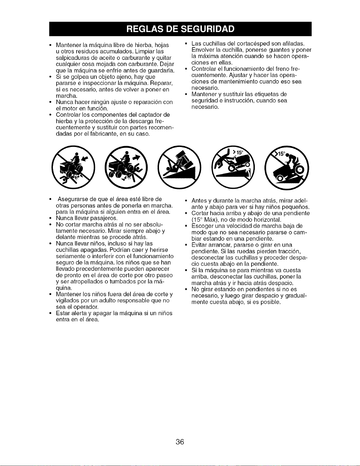
• Mantener la m_.quina libre de hierba, hojas
u otros residuos acumulados. Limpiar las
salpicaduras de aceite o carburante y quitar
cualquier cosa mojada con carburante. Dejar
que la m_.quina se enfrie antes de guardarla.
• Si se golpea un objeto ajeno, hay que
pararse e inspeccionar la m_.quina. Reparar,
si es necesario, antes de volver a poner en
marcha.
• Nunca hacer ningtJn ajuste o reparaci6n con
el motor en funcidn.
• Controlar los componentes del captador de
hierba y la protecci6n de la clescarga fre-
cuentemente y sustituir con partes recomen-
dadas por el fabricante, en su caso.
• Las cuchillas del cortac_sped son afiladas.
Envolver la cuchilla, ponerse guantes y poner
la m_.xima atenci6n cuando se hacen opera-
ciones en elias.
• Controlar el funcionamiento del freno fre-
cuentemente. Ajustar y hacer las opera-
ciones de mantenimiento cuando eso sea
necesario.
• Mantener y sustituir las etiquetas de
seguridad e instrucci6n, cuando sea
necesario.
• Asegurarse de que el _.rea est_ libre de
otras personas antes de ponerla en marcha.
para la m_.quina si alguien entra en el Area.
• Nunca Ilevar pasajeros.
• No cortar marcha atr_.s al no ser absolu-
tamente necesario. Mirar siempre abajo y
delante mientras se procede atr_.s.
• Nunca Ilevar nifios, incluso si hay las
cuchillas apagadas. Podrian caer y herirse
seriamente o interferir con el funcionamiento
seguro de la m_.quina, los nifios que se han
Ilevado precedentemente pueden aparecer
de pronto en el Area de corte por otro paseo
y ser atropellados o tumbados por la m_.-
quina.
• Mantener los nifios fuera del _.rea de corte y
vigilados por un adulto responsable que no
sea el operador.
• Estar alerta y apagar la m_.quina si un nifios
entra en el _.rea.
• Antes y durante la marcha atrdts, mirar adel-
ante y abajo para ver si hay nifios pequefios.
• Cortar hacia arriba y abajo de una pendiente
(15° M_.x), no de modo horizontal.
• Escoger una velocidad de marcha baja de
modo que no sea necesario pararse o cam-
biar estando en una pendiente.
• Evitar arrancar, pararse o girar en una
pendiente. Si las ruedas pierden tracci6n,
desconectar las cuchillas y proceder despa-
cio cuesta abajo en la pendiente.
• Si la m_.quina se para mientras va cuesta
arriba, desconectar las cuchillas, poner la
marcha atr_.s y ir hacia atr_.s despacio.
• No girar estando en pendientes si no es
necesario, y luego girar despacio y gradual-
mente cuesta abajo, si es posible.
36
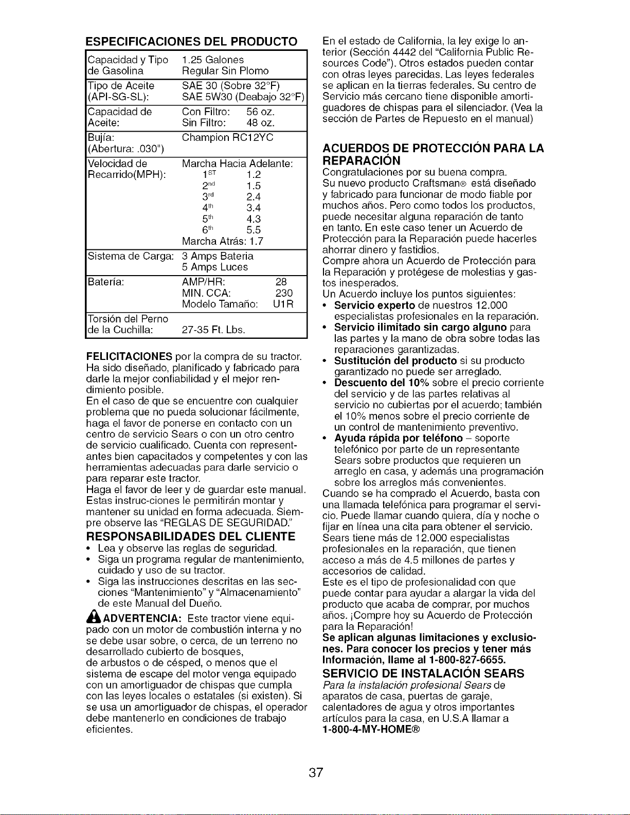
ESPECIFICACIONES DEL PRODUCTO
Capacidad yTipo 1.25 Galones
de Gasolina Regular Sin Plomo
Tipo de Aceite SAE 30 (Sobre 32°F)
API-SG-SL): SAE 5W30 (Deabajo 32°F)
Capacidad de Con Filtro: 56 oz.
Aceite: Sin Filtro: 48 oz.
Bujfa: Champion RC12YC
Abertura: .030")
Velocidad de Marcha Hacia Adelante:
Recarrido(MPH):
1ST 1.2
2n_ 1.5
3rd 2.4
4th 3.4
5th 4.3
6 th 5.5
Marcha Atr_.s: 1.7
Sistema de Carga: 3 Amps Bateria
5 Amps Luces
Bateria: AMP/HR: 28
MIN. CCA: 230
Modelo Tama_o: U1R
Torsidn del Perno
de la Cuchilla: 27-35 Ft. Lbs.
FELIClTAClONES por la compra de su tractor.
Ha sido diseSado, planificado y fabricado para
darle la mejor confiabilidad y el mejor ren-
dimiento posible.
En el caso de que se encuentre con cualquier
problema que no pueda solucionar f_.cilmente,
haga el favor de ponerse en contacto con un
centro de servicio Sears o con un otro centro
de servicio cualificado. Cuenta con represent-
antes bien capacitados y competentes y con las
herramientas adecuadas para darle servicio o
para reparar este tractor.
Haga el favor de leer y de guardar este manual.
Estas instruc-ciones le permitir_.n montar y
mantener su unidad en forma adecuada. Siem-
pre observe las "REGLAS DE SEGURIDAD."
RESPONSABILIDADES DEL CLIENTE
• Lea y observe las reglas de seguridad.
• Siga un programa regular de mantenimiento,
cuidado y uso de su tractor.
• Siga las instrucciones descritas en las sec-
ciones "Mantenimiento" y "Almacenamiento"
de este Manual del DueSo.
,_ADVERTENClA: Este tractor viene equi-
pado con un motor de combusti6n interna y no
se debe usar sobre, o cerca, de un terreno no
desarrollado cubierto de bosques,
de arbustos o de c_sped, o menos que el
sistema de escape del motor venga equipado
con un amortiguador de chispas que cumpla
con las leyes locales o estatales (si existen). Si
se usa un amortiguador de chispas, el operador
debe mantenerlo en condiciones de trabajo
eficientes.
En el estado de California, la ley exige Io an-
terior (Secci6n 4442 del "California Public Re-
sources Code"). Otros estados pueden contar
con otras leyes parecidas. Las leyes federales
se aplican en la tierras federales. Su centro de
Servicio m_ts cercano tiene disponible amorti-
guadores de chispas para el silenciador. (Vea la
secci6n de Partes de Repuesto en el manual)
ACUERDOS DE PROTECCION PARA LA
REPARACION
Congratulaciones por su buena compra.
Su nuevo producto Craftsman® est,. diseSado
y fabricado para funcionar de modo fiable por
muchos aSos. Pero como todos los productos,
puede necesitar alguna reparaci6n de tanto
en tanto. En este caso tener un Acuerdo de
Protecci6n para la Reparaci6n puede hacerles
ahorrar dinero y fastidios.
Compre ahora un Acuerdo de Protecci6n para
la Reparaci6n y prot_gese de molestias y gas-
tos inesperados.
Un Acuerdo incluye los puntos siguientes:
• Servicio experto de nuestros 12.000
especialistas profesionales en la reparaci6n.
• Servicio ilimitado sin cargo alguno para
las partes y la mano de obra sobre todas las
reparaciones garantizadas.
• Sustitucion del producto si su producto
garantizado no puede ser arreglado.
• Descuento del 10% sobre el precio corriente
del servicio y de las partes relativas al
servicio no cubiertas por el acuerdo; tambien
el 10% menos sobre el precio corriente de
un control de mantenimiento preventivo.
• Ayuda rapida por telefono- soporte
telef6nico por parte de un representante
Sears sobre productos que requieren un
arreglo en casa, y adem_.s una programaci6n
sobre los arreglos m_ts convenientes.
Cuando se ha comprado el Acuerdo, basta con
una Ilamada telef6nica para programar el servi-
cio. Puede Ilamar cuando quiera, dfa y noche o
fijar en Ifnea una cita para obtener el servicio.
Sears tiene m_ts de 12.000 especialistas
profesionales en la reparaci6n, que tienen
acceso a m_ts de 4.5 millones de partes y
accesorios de calidad.
Este es el tipo de profesionalidad con que
puede contar para ayudar a alargar la vida del
producto que acaba de comprar, por muchos
ahos. iCompre hoy su Acuerdo de Protecci6n
para la Reparaci6n!
Se aplican algunas limitaciones y exclusio-
nes. Para conocer los precios y tenet mas
Informacion, Ilame al 1-800-827-6655.
SERVIClO DE INSTALACl0N SEARS
Para la instalaciSn profesional Sears de
aparatos de casa, puertas de garaje,
calentadores de agua y otros importantes
artfculos para la casa, en U.S.A Ilamar a
1-800-4-MY-HOME®
37
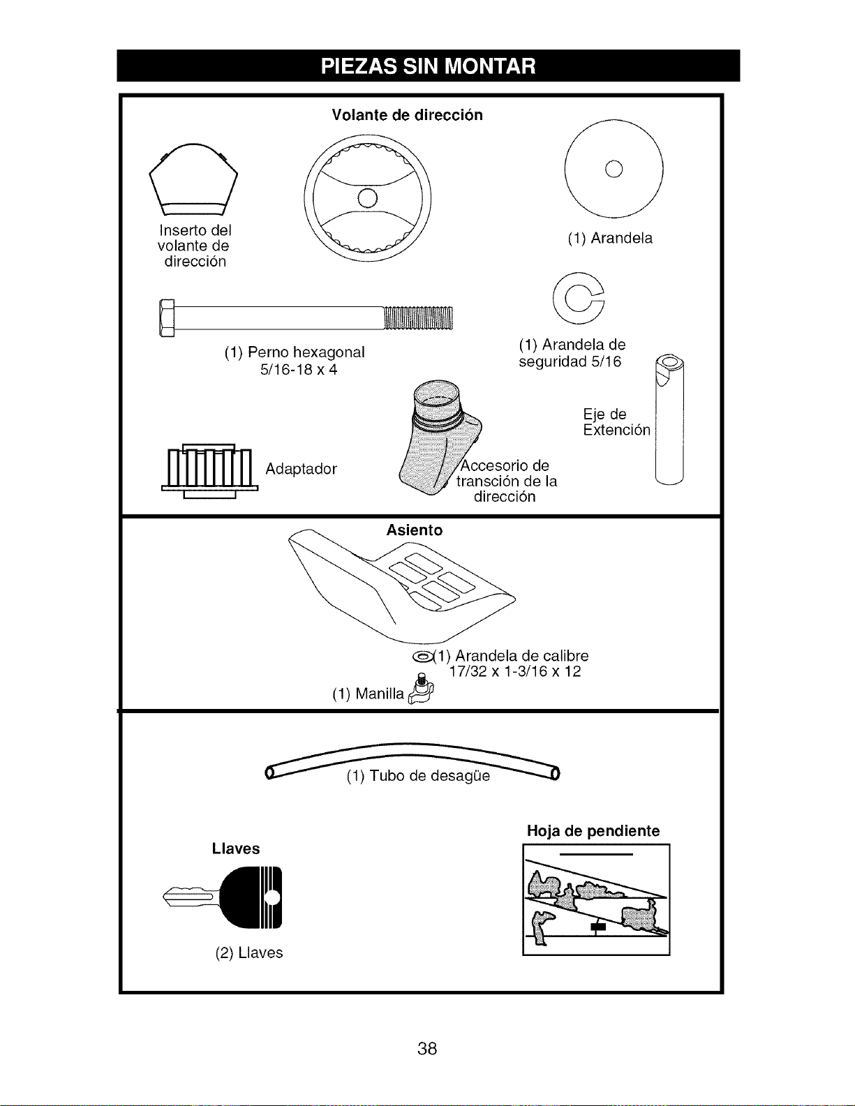
Inserto del
volante de
direccion
Volante de direccion
@
D
(1) Perno hexagonal
5/16-18 x 4
(1) Arandela
©
(1) Arandela de
seguridad 5/16
Adaptador
I I I I
Asiento
_,ccesorio de
transcion de la
direccion
Eje de
Extenci6n
_d
(_(1) Arandela de calibre
Manilla _,_ 17/32 x 1-3/16 x 12
(1)
Llaves
Hoja de pendiente
(2) Llaves
38
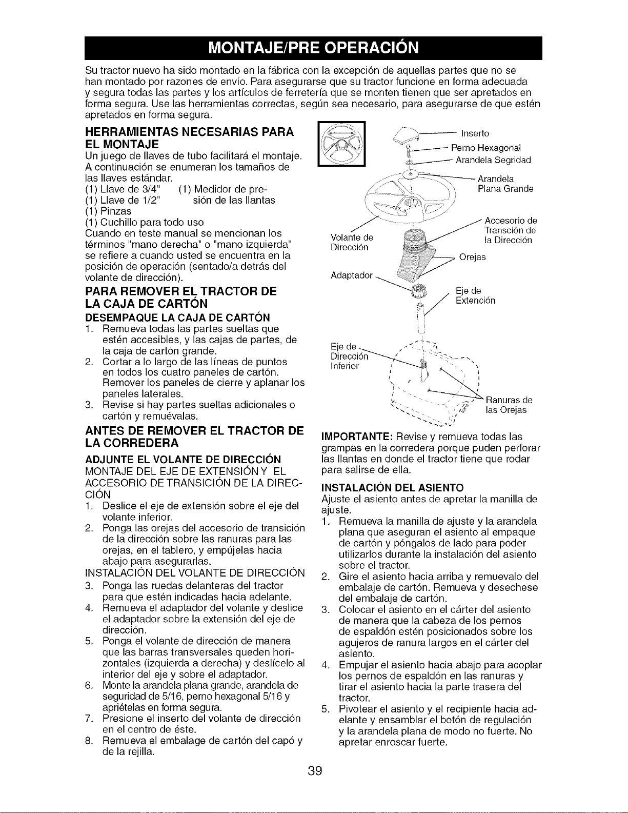
Su tractor nuevo ha side montado en la f_tbrica con la excepci6n de aquellas partes que no se
han montado per razones de envio. Para asegurarse que su tractor funcione en forma adecuada
y segura todas las partes y los articulos de ferreteria que se monten tienen que ser apretados en
forma segura. Use las herramientas correctas, segtJn sea necesario, para asegurarse de que est_n
apretados en forma segura.
HERRAMIENTAS NECESARIAS PARA
EL MONTAJE
Un juego de Ilaves de tube facilitar_, el montaje.
A continuaci6n se enumeran los tamahos de
las Ilaves est_.ndar.
(1) Llave de 3/4" (1) Medidor de pre-
(1) Llave de 1/2" si6n de las Ilantas
(1) Pinzas
(1) Cuchillo para todo use
Cuando en teste manual se mencionan los
terminos "mane derecha" o "mane izquierda"
se refiere a cuando usted se encuentra en la
posici6n de operaci6n (sentado/a detr_.s del
volante de direcci6n).
PARA REMOVER EL TRACTOR DE
LA CAJA DE CARTON
DESEMPAQUE LA CAJA DE CARTON
1. Remueva todas las partes sueltas que
est_n accesibles, y las cajas de partes, de
la caja de cart6n grande.
2. Cortar a Io largo de las lineas de puntos
en todos los cuatro paneles de cart6n.
Remover los paneles de cierre y aplanar los
paneles laterales.
3. Revise si hay partes sueltas adicionales o
cart6n y remuevalas.
ANTES DE REMOVER EL TRACTOR DE
LA CORREDERA
ADJUNTE EL VOLANTE DE DIRECCION
MONTAJE DEL EJE DE EXTENSION Y EL
ACCESORIO DE TRANSICION DE LA DIREC-
CION
1. Deslice el eje de extensi6n sobre el eje del
volante inferior.
2. Ponga las orejas del accesorio de transici6n
de la direcci6n sobre las ranuras para las
orejas, en el tablero, y empt3jelas hacia
abajo para asegurarlas.
INSTALAClON DEL VOLANTE DE DIRECClON
3. Ponga las ruedas delanteras del tractor
para que est_n indicadas hacia adelante.
4. Remueva el adaptador del volante y deslice
el adaptador sobre la extensi6n del eje de
direcci6n.
5. Ponga el volante de direcci6n de manera
que las barras transversales queden hori-
zontales (izquierda a derecha) y deslicelo al
interior del eje y sobre el adaptador.
6. Monte la arandela plana grande, arandela de
seguridad de 5/16, pemo hexagonal 5/16 y
apri_telas en forma segura.
7. Presione el inserto del volante de direcci6n
en el centre de este.
8. Remueva el embalage de cart6n del cap6 y
de la rejilla.
;_ Inserto
_._----- Perno Hexagonal
_,__._..------ Arandela Segridad
Arandela
Plana Grande
L9
Eje de _ . _ L ,q
Direcci6n-""----._ _ ".-_...... ,
Inferior / _ _. "- ,
aanuras_ - j
_. "- de
. _,,_ las Orejas
IMPORTANTE: Revise y remueva todas las
grampas en la corredera porque puden perforar
las Ilantas en donde el tractor tiene que rodar
para salirse de ella.
INSTALACION DEL ASIENTO
Ajuste el asiento antes de apretar la manilla de
ajuste.
1. Remueva la manilla de ajuste y la arandela
plana que aseguran el asiento al empaque
de cart6n y p6ngalos de lade para poder
utilizarlos durante la instalaci6n del asiento
sobre el tractor.
2. Gire el asiento hacia arriba y remuevalo del
embalaje de cart6n. Remueva y desechese
del embalaje de cart6n.
3. Colocar el asiento en el carter del asiento
de manera que la cabeza de los pernos
de espald6n est_n posicionados sobre los
agujeros de ranura largos en el c_.rter del
asiento.
4. Empujar el asiento hacia abajo para acoplar
los pernos de espald6n en las ranuras y
tirar el asiento hacia la parte trasera del
tractor.
5. Pivotear el asiento y el recipiente hacia ad-
elante y ensamblar el bot6n de regulaci6n
y la arandela plana de mode no fuerte. No
apretar enroscar fuerte.
39
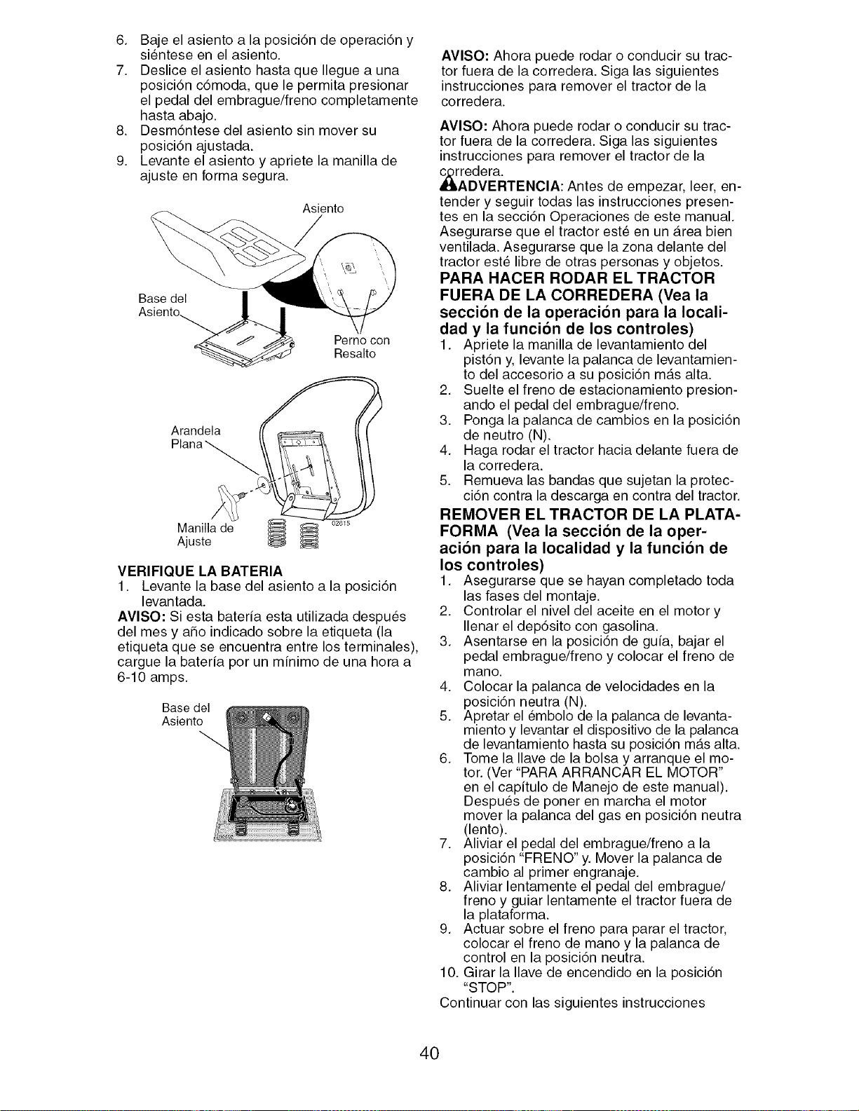
6. Baje el asiento a la posici6n de operaci6n y
sientese en el asiento.
7. Deslice el asiento hasta que Ilegue a una
posici6n cdmoda, que le permita presionar
el pedal del embrague/freno completamente
hasta abajo.
8. Desm6ntese del asiento sin mover su
posici6n ajustada.
9. Levante el asiento y apriete la manilla de
ajuste en forma segura.
Asiento
Base del
Perno con
Resalto
Arandela
Manilla de
Ajuste
VERIFIQUE LA BATERIA
1. Levante la base del asiento a la posici6n
levantada.
AVlSO: Si esta bateria esta utilizada despues
del mes y aho indicado sobre la etiqueta (la
etiqueta que se encuentra entre los terminales),
cargue la bateria por un minimo de una hora a
6-10 amps.
Base del
Asiento
AVISO: Ahora puede rodar o conducir su trac-
tor fuera de la corredera. Siga las siguientes
instrucciones para remover el tractor de la
corredera.
AVISO: Ahora puede rodar o conducir su trac-
tor fuera de la corredera. Siga las siguientes
instrucciones para remover el tractor de la
_rAredera.
DVERTENClA: Antes de empezar, leer, en-
tender y seguir todas las instrucciones presen-
tes en la secci6n Operaciones de este manual.
Asegurarse que el tractor este en un Area bien
ventilada. Asegurarse que la zona delante del
tractor este libre de otras personas y objetos.
PARA HACER RODAR EL TRACTOR
FUERA DE LA CORREDERA (Vea la
secci6n de la operaci6n para la Iocali-
dad y la funci6n de los controles)
1. Apriete la manilla de levantamiento del
pist6n y, levante la palanca de levantamien-
to del accesorio a su posici6n m_.s alta.
2. Suelte el freno de estacionamiento presion-
ando el pedal del embrague/freno.
3. Ponga la palanca de cambios en la posici6n
de neutro (N).
4. Haga rodar el tractor hacia delante fuera de
la corredera.
5. Remueva las bandas que sujetan la protec-
ci6n contra la descarga en contra del tractor.
REMOVER EL TRACTOR DE LA PLATA-
FORMA (Vea la secci6n de la oper-
aci6n para la Iocalidad y la funci6n de
los controles)
1. Asegurarse que se hayan completado toda
las fases del montaje.
2. Controlar el nivel del aceite en el motor y
Ilenar el depdsito con gasolina.
3. Asentarse en la posici6n de guia, bajar el
pedal embrague/freno y colocar el freno de
mano.
4. Colocar la palanca de velocidades en la
posici6n neutra (N).
5. Apretar el embolo de la palanca de levanta-
miento y levantar el dispositivo de la palanca
de levantamiento hasta su posici6n m_ts alta.
6. Tome la Ilave de la bolsa y arranque el mo-
tor. (Ver "PARA ARRANCAR EL MOTOR"
en el capitulo de Manejo de este manual).
Despu_s de poner en marcha el motor
mover la palanca del gas en posici6n neutra
(lento).
7. Aliviar el pedal del embrague/freno a la
posici6n "FRENO" y. Mover la palanca de
cambio al primer engranaje.
8. Aliviar lentamente el pedal del embrague/
freno y guiar lentamente el tractor fuera de
la plataforma.
9. Actuar sobre el freno para parar el tractor,
colocar el freno de mano y la palanca de
control en la posici6n neutra.
10. Girar la Ilave de encendido en la posici6n
"STOP".
Continuar con las siguientes instrucciones
40
REVISION DE LA PRESION DE LAS
LLANTAS
Las Ilantas en su tractor fueron infladas de-
masiado en la f_.brica por razones de envfo. La
presi6n de las Ilantas correctas es importante
para obtener el mejor rendimiento en el corte.
• Reduzca la presi6n de las Ilantas a la PSI.
REVISlC)N DE LA NIVELAClC)N DEL
CONJUNTO
Para obtener los mejores resultados en el corte,
la caja de la segadora tiene que estar nivelada
en la forma adecuada. Vea "PARA NIVELAR
LA CAJA DE LA SEGADORA" en la secci6n de
Servicio y Ajustes de este manual.
REVISlC)N DE LA POSlClON ADECUA-
DA DE TODAS LAS CORREAS
Vea las figuras que aparecen para cambiar
las correas de impulsi6n de la cuchilla de la
segadora y de movimiento en la secci6n de
Servicio y Ajustes de este manual. Verifique uq
las correas sigan su paso correcto.
REVISION DEL SlSTEMA DE FRENOS
Una vez que usted haya aprendido a mane-
jar su tractor, verifique que el freno funcione
correctamente. Ver"PARA VERIFICAR SI
FUNCIONA BIEN EL FRENO" en el capftulo de
servicio y ajustes de este manual.
,/LISTA DE REVISION
ANTES DE OPERAR Y DE DISFRUTAR DE SU
TRACTOR NUEVO, LE DESEAMOS QUE RE-
CIBA EL MEJOR RENDIMIENTOY LA MAYOR
SATISFACCION DE ESTE PRODUCTO DE
CALIDAD.
HAGA EL FAVOR DE REVISAR LA LISTA A
CONTINUACION:
,/ Se han completado todas las instrucciones
de montaje.
,/ No quedan partes sueltas en la caja de
cart6n.
,/ La baterfa ester preparada y cargada en
forma adecuada.
,/ El asiento ha sido ajustado en forma c6moda
y apretado en forma segura.
,/Todas las Ilantas han sido infladas en forma
adecuada. (Para fines de envfo, las Ilantas se
inflaron demasiado en la f_.brica.)
,/AsegQrese que el conjunto segador este
nivelado en forma adecuada, de lado a lado
y desde adelante hacia atr_ts, para obtener
los mejores resultados en el corte. (Las
Ilantas tienen que estar infladas en forma
adecuada para la nivelaci6n.)
,/ Revise las correas de impulsi6n y de la
segadora. AsegQrese que recorran el paso
adecuado alrededor de las poleas y dentro
de todos los fijadores de las correas.
,/ Revise el alambrado. Ffjese que todas las
conexiones todavfa esten seguras y que los
alambres est_n sujetos en forma adecuada.
AL MISMO TIEMPO QUE APRENDE A COMO
USAR SU TRACTOR, PRESTE ATENCION EX-
TRA A LOS PUNTOS DE IMPORTANCIA QUE
SE PRESENTAN A CONTINUACION:
,/ El aceite del motor tiene que Ilegar al nivel
adecuado.
,/ El estanque de combustible tiene que estar
Ileno con gasolina sin plomo regular, nueva y
limpia.
,/ Familiarfcese con todos los controles - su
ubicaci6n y su funci6n. Op_relos antes de
hacer arrancar el motor.
,/AsegQrese que el sistema de frenos este en
una condici6n de operaci6n segura.
,/Asegurarse de que el Sistema de
Presencia del Operador y el Sistema de
Funcionamiento Atr_ts (ROS) funcionan
de modo adecuado (Ver las Secciones de
Funcionamiento y Mantenimiento en este
manual).
41
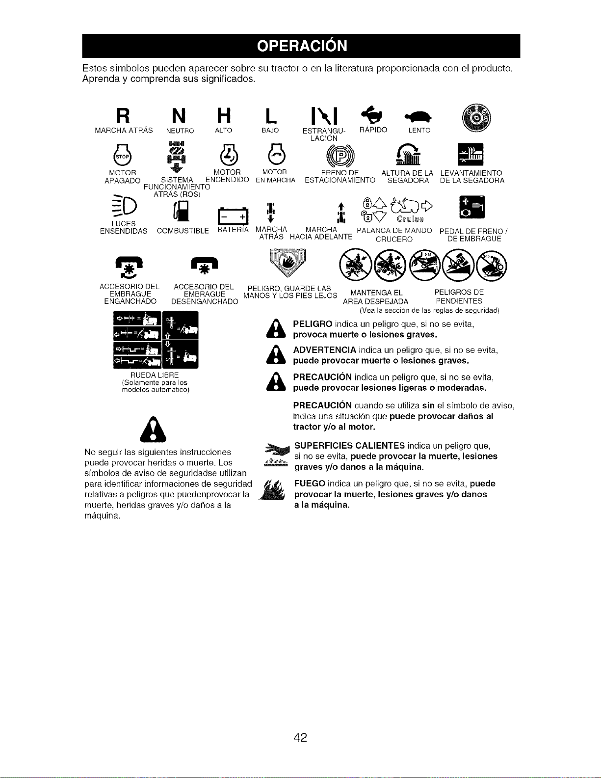
Estos simbolos pueden aparecer sobre su tractor o en la literatura proporcionada con el producto.
Aprenda y comprenda sus significados.
R N H I'.,I
MARCHA ATR,_,S NEUTRO ALTO BAJO ESTRANGU- R,_PIDO
LACI6N
- G (@)
MOTOR _ MOTOR MOTOR FRENO DE
APAGADO SISTEMA ENCENDIDO EN MARCHA ESTACIONAMIENTO
FUNCIONAMIENTO
ATRAS(ROS)
LUCES
ENSENDIDAS
E9
COMBUSTIBLE BATERIA
ACCESORIO DEL ACCESORIO DEL
EMBRAGUE EMBRAGUE
ENGANCHADO DESENGANCHADO
RUEDA LIBRE
(Solamente para los
modelos automatico)
&
LENTO
ALTURA DE LA LEVANTAMIENTO
SEGADORA DE LA SEGADORA
MARC, HA MARCHA PALANCA DE MANDO PEDAL DE FRENO /
ATRAS HACIA ADELANTE CRUCERO DE EMBRAGUE
PELIGRO, GUARDE LAS
MANOS Y LOS PIES LEJOS MANTENGA EL PEUGROS DE
AREA DESPEJADA PENDIENTES
(Vea la seccion de las reglas de seguridad)
PELIGRO indica un peligro que, si no se evita,
provoca muerte o lesiones graves.
ADVERTENCIA indica un peligro que, si no se evita,
puede provocar muerte o lesiones graves.
PRECAUCION indica un peligro que, si no se evita,
puede provocar lesiones ligeras o moderadas.
PRECAUClON cuando se utiliza sin el sfmbolo de aviso,
indica una situacidn que puede provocar daSos al
tractor y/o al motor.
No seguir las siguientes instrucciones
puede provocar heridas o muerte. Los
simbolos de aviso de seguridadse utilizan
para identificar informaciones de seguridad
relativas a peligros que puedenprovocar la
muerte, heridas graves y/o da_os a la
maquina.
,Jh_IlIBSJll/_.
SUPERFICIES CALIENTES indica un peligro que,
si no se evita, puede provocar la muerte, lesiones
graves y/o danes a la m_iquina.
FUEGO indica un peligro que, si no se evita, puede
provocar la muerte, lesiones graves y/o danos
a la m_iquina.
42
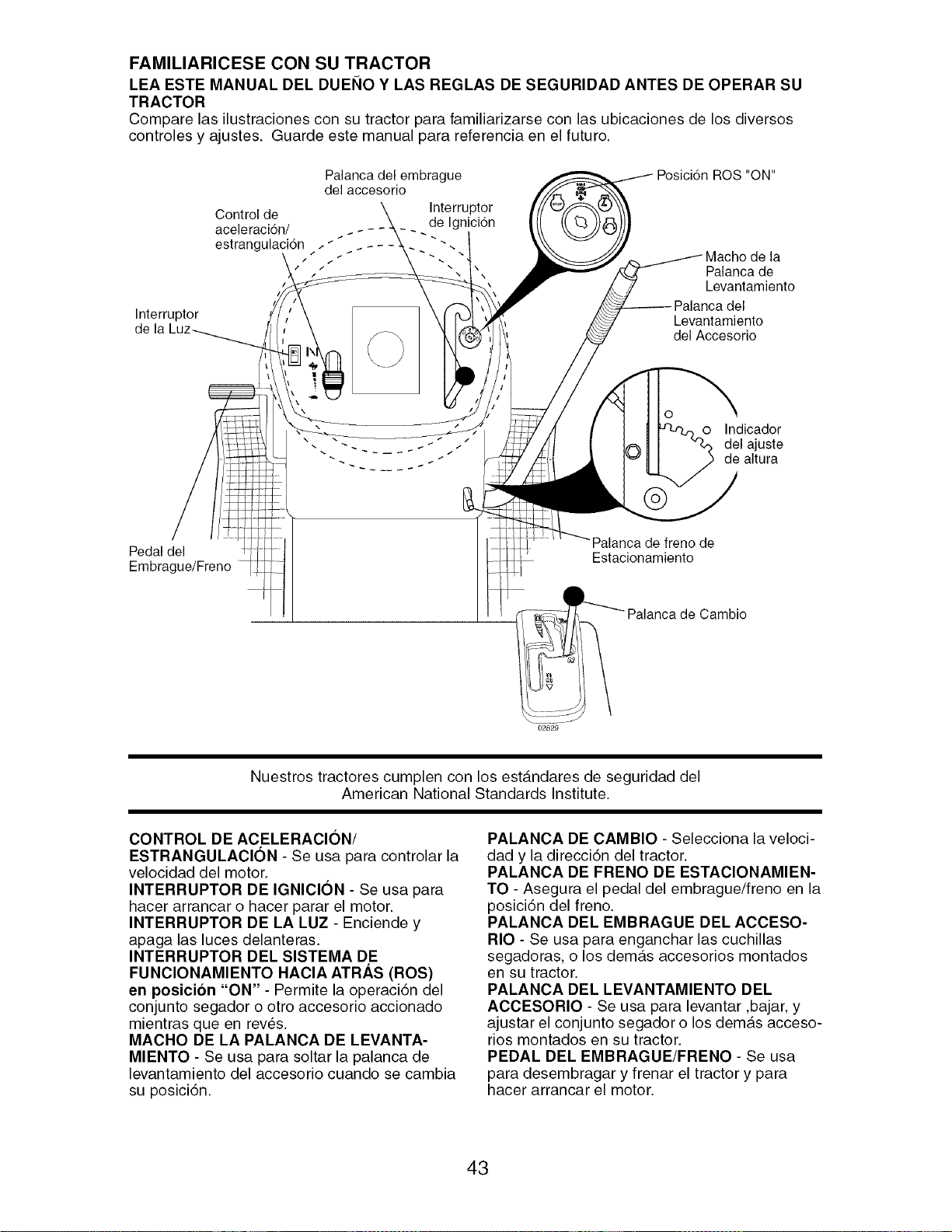
FAMILIARICESE CON SU TRACTOR
LEA ESTE MANUAL DEL DUEI_IO Y LAS REGLAS DE SEGURIDAD ANTES DE OPERAR SU
TRACTOR
Compare las ilustraciones con su tractor para familiarizarse con las ubicaciones de los diversos
controles y ajustes. Guarde este manual para referencia en el futuro.
Palanca del embrague ROS "ON"
del accesorio
Control de
aceleraci6n/
estrangulaci6n / _ .- -
!
L!
Interruptor
de la kuz_ I_
Interruptor
de Ignicidn
-:--.1
Macho de la
Palanca de
Levantamiento
Levantamiento
del Accesorio
O
o Indicador
del ajuste
de altura
Pedal del
Embrague/Freno
Palanca de freno de
Estacionamiento
Cambio
02829
Nuestros tractores cumplen con los est_.ndares de seguridad del
American National Standards Institute.
CONTROL DE ACELERACION/
ESTRANGULACION - Se usa para controlar la
velocidad del motor.
INTERRUPTOR DE IGNICION - Se usa para
hacer arrancar o hacer parar el motor.
INTERRUPTOR DE LA LUZ - Enciende y
apaga las luces delanteras.
INTERRUPTOR DEL SlSTEMA DE
FUNClONAMIENTO HAClA ATRAS (ROS)
en posicion "ON" - Permite la operaci6n del
conjunto segador o otro accesorio accionado
mientras queen rev_s.
MACHO DE LA PALANCA DE LEVANTA-
MIENTO - Se usa para soltar la palanca de
levantamiento del accesorio cuando se cambia
su posicidn.
PALANCA DE CAMBIO - Selecciona la veloci-
dad y la direccidn del tractor.
PALANCA DE FRENO DE ESTAClONAMIEN-
TO - Asegura el pedal del embrague/freno en la
posicidn del freno.
PALANCA DEL EMBRAGUE DEL ACCESO-
RIO - Se usa para enganchar las cuchillas
segadoras, o los demurs accesorios montados
en su tractor.
PALANCA DEL LEVANTAMIENTO DEL
ACCESORIO - Se usa para levantar ,bajar, y
ajustar el conjunto segador o los dem_.s acceso-
rios montados en su tractor.
PEDAL DEL EMBRAGUE/FRENO - Se usa
para desembragar y frenar el tractor y para
hacer arrancar el motor.
43
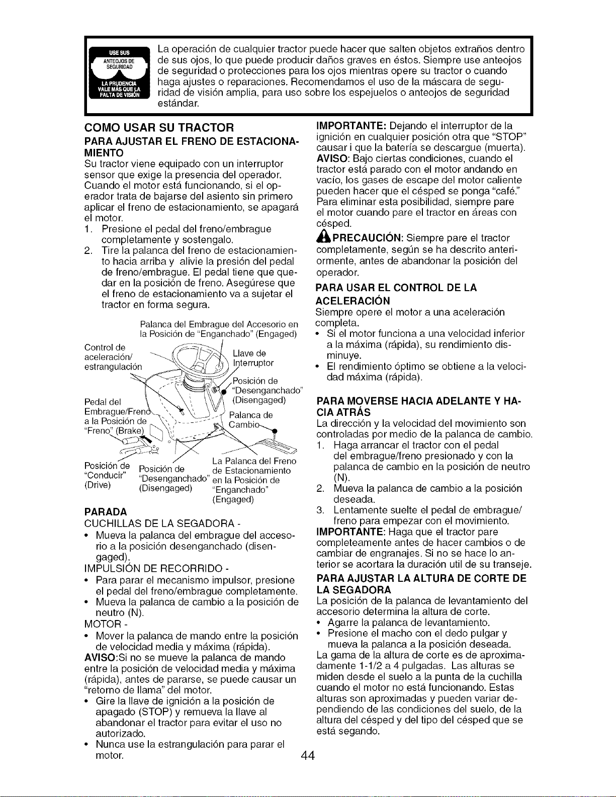
La operaci6n de cualquier tractor puede hacer que salten objetos extrahos dentro
de sus ojos, Io que puede producir daSos graves en _stos. Siempre use anteojos
de seguridad o protecciones para los ojos mientras opere su tractor o cuando
haga ajustes o reparaciones. Recomendamos el uso de la mascara de segu-
ridad de visidn amplia, para uso sobre los espejuelos o anteojos de seguridad
est_.ndar.
COMO USAR SU TRACTOR
PARA AJUSTAR EL FRENO DE ESTACIONA-
MIENTO
Su tractor viene equipado con un interruptor
sensor que exige la presencia del operador.
Cuando el motor ester funcionando, si el op-
erador trata de bajarse del asiento sin primero
aplicar el freno de estacionamiento, se apagar_t
el motor.
1. Presione el pedal del freno/embrague
completamente y sostengalo.
2. Tire la palanca del freno de estacionamien-
to hacia arriba y alivie la presi6n del pedal
de freno/embrague. El pedal tiene que que-
dar en la posicidn de freno. AsegtJrese que
el freno de estacionamiento va a sujetar el
tractor en forma segura.
Palanca del Embrague del Accesorio en
la Posicidn de "Enganchado" (Engaged)
Control de
aceleracidn/
estrangulaci6n
Pedal del
Embrague/Frer
a la Posici6n de
"Freno"
Llave de
Posicidn de
anchado"
(Disengaged)
Palanca de
La Palancadel Freno
Posici6nde Posici6n de de Estacionamiento
"Conducir" "Desenganchado"en la Posicidn de
(Drive) (Disengaged) "Enganchado"
(Engaged)
PARADA
CUCHILLAS DE LA SEGADORA -
• Mueva la palanca del embrague del acceso-
rio a la posici6n desenganchado (disen-
gaged):
IMPULSION DE RECORRIDO -
• Para parar el mecanismo impulsor, presione
el pedal del freno/embrague completamente.
• Mueva la palanca de cambio a la posici6n de
neutro (N).
MOTOR -
• Mover la palanca de mando entre la posici6n
de velocidad media y m_txima (r_.pida).
AVlSO:Si no se mueve la palanca de mando
entre la posici6n de velocidad media y m_.xima
(r_.pida), antes de pararse, se puede causar un
"retorno de llama" del motor.
• Gire la Ilave de ignici6n a la posici6n de
apagado (STOP) y remueva la Ilave al
abandonar el tractor para evitar el uso no
autorizado.
• Nunca use la estrangulaci6n para parar el
motor.
IMPORTANTE: Dejando el interruptor de la
ignici6n en cualquier posici6n otra que "STOP"
causar i que la bateria se descargue (muerta).
AVISO: Bajo ciertas condiciones, cuando el
tractor ester parado con el motor andando en
vacio, los gases de escape del motor caliente
pueden hacer que el c_sped se ponga "caf&"
Para eliminar esta posibilidad, siempre pare
el motor cuando pare el tractor en Areas con
c_sped.
_lb PRECAUClON: Siempre pare el tractor
completamente, segtJn se ha descrito anteri-
ormente, antes de abandonar la posici6n del
operador.
PARA USAR EL CONTROL DE LA
ACELERAClON
Siempre opere el motor a una aceleraci6n
completa.
• Si el motor funciona a una velocidad inferior
a la m_txima (r_tpida), su rendimiento dis-
minuye.
• El rendimiento 6ptimo se obtiene a la veloci-
clad maxima (r_tpida).
PARA MOVERSE HAClA ADELANTE Y HA-
ClA ATRAS
La direcci6n y la velocidad del movimiento son
controladas por medio de la palanca de cambio.
1. Haga arrancar el tractor con el pedal
del embrague/freno presionado y con la
palanca de cambio en la posici6n de neutro
(N).
2. Mueva la palanca de cambio a la posici6n
deseada.
3. Lentamente suelte el pedal de embrague/
freno para empezar con el movimiento.
IMPORTANTE: Haga que el tractor pare
completeamente antes de hacer cambios o de
cambiar de engranajes. Si no se hace Io an-
terior se acortara la duraci6n util de su transeje.
PARA AJUSTAR LA ALTURA DE CORTE DE
LA SEGADORA
La posici6n de la palanca de levantamiento del
accesorio cletermina la altura de corte.
• Agarre la palanca de levantamiento.
• Presione el macho con el dedo pulgar y
mueva la palanca a la posici6n deseada.
La gama de la altura de corte es de aproxima-
damente 1-1/2 a 4 pulgadas. Las alturas se
miden desde el suelo a la punta de la cuchilla
cuando el motor no esterfuncionando. Estas
alturas son aproximadas y pueden variar de-
pendiendo de las condiciones del suelo, de la
altura del cesped y del tipo del cespecl que se
est.. segando.
44
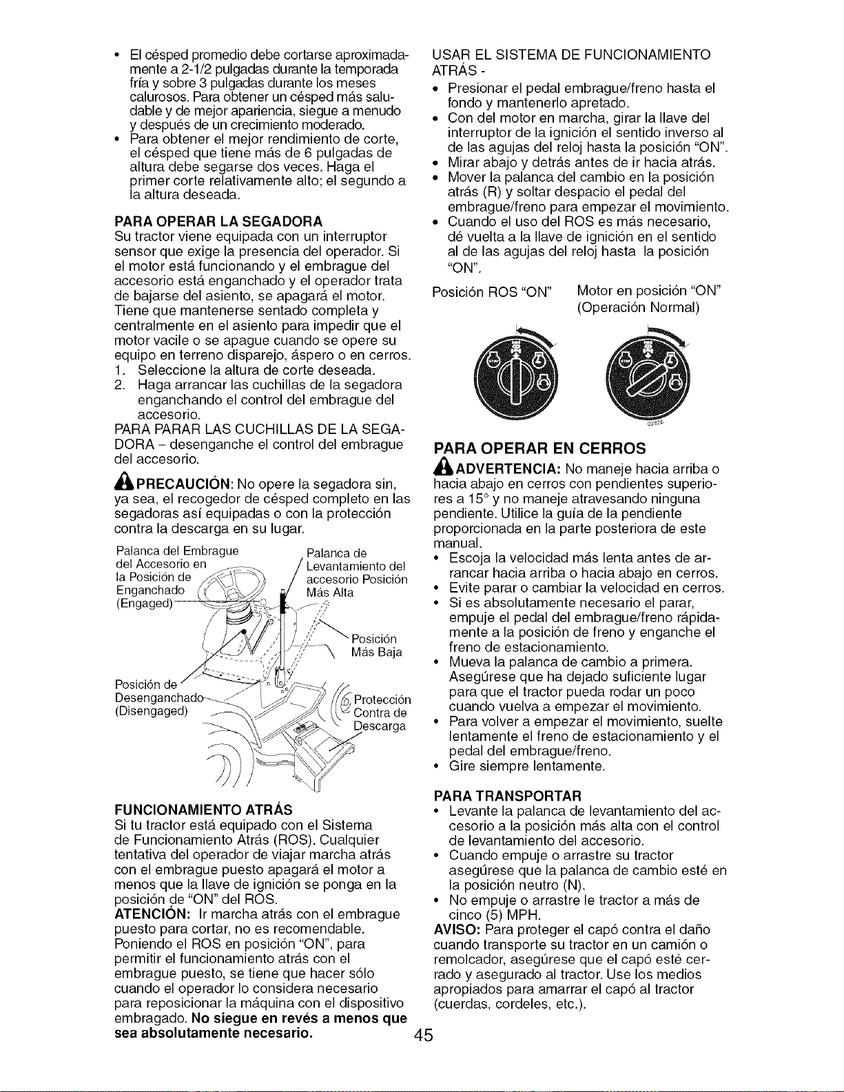
• El c6sped promedio debe cortarse aproximada-
mente a 2-1/2 pulgadas durante la temporada
fria y sobre 3 pulgadas durante los meses
calurosos. Para obtener un cesped m_.s salu-
dable y de mejor apariencia, siegue a menudo
y despu6s de un crecimiento moderado.
• Para obtener el mejor rendimiento de corte,
el c6sped que tiene m_.s de 6 pulgadas de
altura debe segarse dos veces. Haga el
primer corte relativamente alto; el segundo a
la altura deseada.
PARA OPERAR LA SEGADORA
Su tractor viene equipada con un interruptor
sensor que exige la presencia del operador. Si
el motor ester funcionando y el embrague del
accesorio ester enganchado y el operador trata
de bajarse del asiento, se apagar_t el motor.
Tiene que mantenerse sentado completa y
centralmente en el asiento para impedir que el
motor vacile o se apague cuando se opere su
equipo en terreno disparejo, _.spero o en cerros.
1. Seleccione la altura de corte deseada.
2. Haga arrancar las cuchillas de la segadora
enganchando el control del embrague del
accesorio.
PARA PARAR LAS CUCHILLAS DE LA SEGA-
DORA - desenganche el control del embrague
del accesorio.
_I_PRECAUCION: No opere la segadora sin,
ya sea, el recogedor de cesped completo en las
segadoras asi equipadas o con la protecci6n
contra la descarga en su lugar.
Palanca del Embrague
del Accesorio en
la Posici6n de
Enganchado
Palanca de
accesorio Posici6n
Mas Alta
Posici6n de
Desenganchado--_
(Disengaged)
Posici6n
Mas Baja
/_ Protecci6n
k\_ Contra de
Descarga
USAR EL SISTEMA DE FUNCIONAMIENTO
ATRAS -
• Presionar el pedal embrague/freno hasta el
rondo y mantenerlo apretado.
• Con del motor en marcha, girar la Ilave del
interruptor de la ignici6n el sentido inverso al
de las agujas del reloj hasta la posici6n "ON".
• Mirar abajo y detr_ts antes de ir hacia atr_.s.
• Mover la palanca del cambio en la posici6n
atr_ts (R) y soltar despacio el pedal del
embrague/freno para empezar el movimiento.
• Cuando el uso del ROSes m_.s necesario,
de vuelta a la Ilave de ignici6n en el sentido
al de las agujas del reloj hasta la posici6n
"ON".
Posici6n ROS "ON" Motor en posici6n "ON"
(Operaci6n Normal)
PARA OPERAR EN CERROS
_IbADVERTENCIA: No maneje hacia arriba o
hacia abajo en cerros con pendientes superio-
res a 15 ° y no maneje atravesando ninguna
pendiente. Utilice la guia de la pendiente
proporcionada en la parte posteriora de este
manual.
• Escoja la velocidad m_.s lenta antes de ar-
rancar hacia arriba o hacia abajo en cerros.
• Evite parar o cambiar la velocidad en cerros.
• Si es absolutamente necesario el parar,
empuje el pedal del embrague/freno r_.pida-
mente a la posici6n de freno y enganche el
freno de estacionamiento.
• Mueva la palanca de cambio a primera.
AsegOrese que ha dejado suficiente lugar
para que el tractor pueda rodar un poco
cuando vuelva a empezar el movimiento.
• Para volver a empezar el movimiento, suelte
lentamente el freno de estacionamiento y el
pedal del embrague/freno.
• Gire siempre lentamente.
FUNCIONAMIENTO ATRAS
Si tu tractor ester equipado con el Sistema
de Funcionamiento Atr_.s (ROS). Cualquier
tentativa del operador de viajar marcha atr_ts
con el embrague puesto apagar_, el motor a
menos que la Ilave de ignici6n se ponga en la
posici6n .de "ON" del ROS.
ATENClON: Ir marcha atr_.s con el embrague
puesto para cortar, no es recomendable.
Poniendo el ROSen posici6n "ON", para
permitir el funcionamiento atr_.s con el
embrague puesto, se tiene que hacer s61o
cuando el operador Io considera necesario
para reposicionar la m_.quina con el dispositivo
embragado. No siegue en reves a menos que
sea absolutamente necesario.
PARA TRANSPORTAR
• Levante la palanca de levantamiento del ac-
cesorio a la posici6n m_ts alta con el control
de levantamiento del accesorio.
• Cuando empuje o arrastre su tractor
asegOrese que la palanca de cambio este en
la posici6n neutro (N).
• No empuje o arrastre le tractor a m_.s de
cinco (5) MPH.
AVlSO" Para proteger el cap6 contra el daSo
cuando transporte su tractor en un cami6n o
remolcador, asegOrese que el cap6 este cer-
rado y asegurado al tractor. Use los medios
apropiados para amarrar el cap6 al tractor
(cuerdas, cordeles, etc.).
45
REMOLQUE DE CARRETILLAS O OTROS
ACCESORIOS
Remolque solamente los accesorios reco-
mendados y especificados por el fabricante
del tractor. Use sentido comt3n cuado este
remolcando. Las cargas pesadas, cuando este
yendo sobre una pendiente, son peligrosas, las
Ilantas pueden perder su tracci6n con el terreno
y pueden ocasionar que pierda el control de su
tractor.
ANTES DE HACER ARRANCAR EL
MOTOR
REVISE EL NIVEL DE ACEITE DEL MOTOR
El motor en su tractor ha sido enviado desde la
f_.brica Ileno con aceite de calidad para verano.
1. Revise el aceite del motor con el tractor en
terreno nivelado.
2. Remueva la tapaJvarilla indicadora de nivel
de relleno del aceite y limpielas, vuelva
a insertar la varilla indicadora de nivel y
atornille la tapa hasta que quede apre-
tad& espere por unos cuantos segundos,
remuevala y lea el nivel del aceite. Si es
necesario, agregue aceite hasta que se
haya alcanzado la marca Ileno (FULL) en
la varilla indicadora de nivel. No Io Ilene
demasiado.
• Para la operaci6n en clima frio, debe cambiar
el aceite para poder arrancar m_ts f_.cilmente
(Vea "Tabla de Viscosidad Del Aceite" en la
secci6n de Mantenimento de este manual).
• Para cambiar el aceite del motor, vea la sec-
ci6n de Mantenimento en este manual.
AGREGUE GASOLINA
• Llene el estanque de combustible. Llene has-
ta la parte inferior del cuello de relleno del
estanque de gasolina. No Io Ilene demasiado.
Use gasolina regular, sin plomo, nueva y lim-
pia con el mfnimo de 87 octanos. (El uso de
gasolina con plomo aumentar_, los dep6sitos
de 6xido de plomo y carbono y se reducirgt la
duraci6n de la v_.lvula). No mezcle el aceite
con la gasolina. Para asegurar que la gaso-
lina utilizada sea fresca compre estanques
los cuales puedan ser utilizados durante los
primeros 30 dfas.
_IPRECAUCl6N: Limpie el aceite o el com-
bustible derramado. No almacene, derrame o
use gasolina cerca de una llama expuesta.
IMPORTANTE: Cuando se opere en temperatu-
ras por debajo de 32°F (0°C) use gasolina de
invierno limpia y nueva para auedar a asegurar
un buen arranque en clima fifo.
PRECAUClON: Combustibles mezclados con
alcohol (conocidos como gasohol, o el uso de
etanol o metanol) pueden atraer la humedad,
la que conduce a la separaci6n y formaci6n de
_.cidos durante el almacenamiento. La gasolina
acfdica puede dafiar el sistema del combustible
de un motor durante el almacenamiento. Para
evitar los problemas con el motor, se debe
vaciar el sistema de combustible antes de
guardarlo por un perfodo de 30 dfas o m_ts.
Vacfe el estanque de combustible, haga arran-
car el motor y h_tgalo funcionar hasta que las
Ifneas del combustible y el carburador queden
vacfos. La pr6xima temporada use combustible
nuevo.
Vea las Instrucciones para el Almacenamiento
para mgts informaci6n. Nunca use productos de
limpieza para el motor o para el carburador en
el estanque del combustible pues se pueden
producir daSos permanentes.
PARA HACER ARRANCAR EL MOTOR
AI hacer arrancar el motor por la primera vez o
si se ha acabado el combustible del motor, se
necesitargt tiempo para el arranque extra para
mover el combustible desde el estanque hasta
el motor.
1. Si_ntase en el sill6n en la posici6n de oper-
aci6n, suelte el pedal del embrague/freno y
ponga el freno de estacionamiento.
2. Ponga la palanca de cambio en la posici6n
de neutro(n).
3. Mueva el embrague del accesorio a la
posici6n desenganchado disengaged.
4. Mueva la palanca de control de la aceler-
aci6n a la posici6n de estrangulaci6n.
AVlSO" Antes de arrancar, lea las instruccio-
nes siguientes para el arranque en clima fifo y
templado.
5. Inserte la Ilave en la ignici6n y gire la Ilave
en el sentido que giran las manillas del reloj
a la posici6n de arranque start, y suelte la
Ilave tan pronto como arranque el motor.
No haga funcionar el arrancador continu-
amente por mgts de quince segundos por
minuto. Si el motor no arranca despues de
intentarlo varias veces, mueva el control de
la aceleraci6n a la posici6n de r_.pido, es-
pere unos cuantos minutos y trate de nuevo.
Si el motor sigue sin funcionar, mueva el
control de la aceleraci6n a la posici6n de
estrangulaci6n y intente de nuevo.
ARRANQUE CON TIEMPO TEMPLADO (50 °
Y MAS)
6. Cuando arranque el motor, mueva el control
de la aceleraci6n a la posici6n de rgtpido.
• Los accesorios y el embrague ahora pueden
ser utilizados. Si el motor no acepta esta car-
ga, vuelva a arrancar el motor para permitirle
que se caliente por un minuto utilizando el
estrangulador como describido arriba.
46
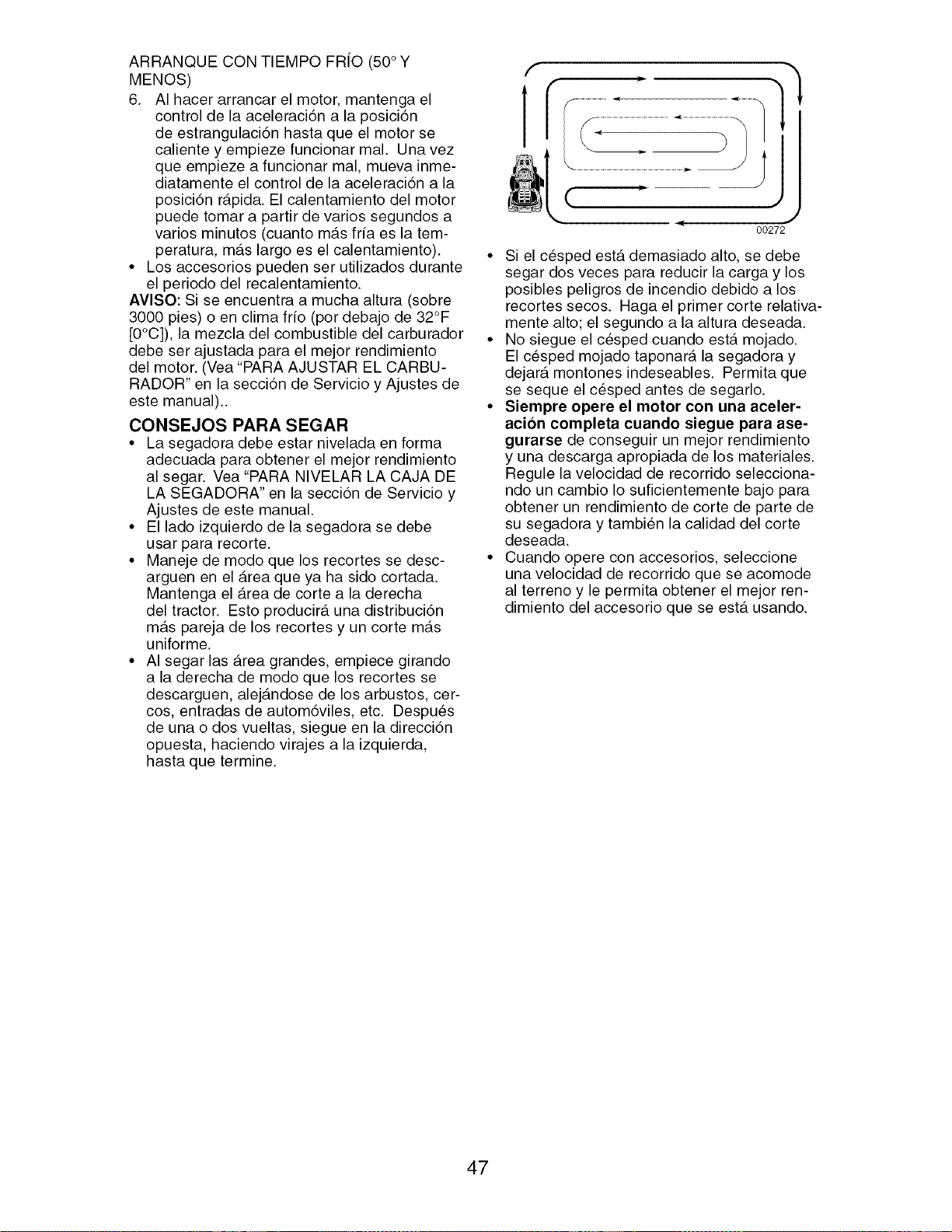
ARRANQUE CON TIEMPO FR[O (50°Y
MENOS)
6. AI hacer arrancar el motor, mantenga el
control de la aceleraci6n a la posici6n
de estrangulaci6n hasta que el motor se
caliente y empieze funcionar mal. Una vez
que empieze a funcionar mal, mueva inme-
diatamente el control de la aceleraci6n a la
posici6n r_tpida. El calentamiento del motor
puede tomar a partir de varios segundos a
varios minutos (cuanto m_.s fria es la tem-
peratura, m_.s largo es el calentamiento).
• Los accesorios pueden ser utilizados durante
el periodo del recalentamiento.
AVlSO: Si se encuentra a mucha altura (sobre
3000 pies) o en clima frio (por debajo de 32°F
[0°C]), la mezcla del combustible del carburador
debe ser ajustada para el mejor rendimiento
del motor. (Vea "PARA AJUSTAR EL CARBU-
RADOR" en la secci6n de Servicio y Ajustes de
este manual)..
CONSEJOS PARA SEGAR
• La segadora debe estar nivelada en forma
adecuada para obtener el mejor rendimiento
al segar. Vea "PARA NIVELAR LA CAJA DE
LA SEGADORA" en la secci6n de Servicio y
Ajustes de este manual.
• El lado izquierdo de la segadora se debe
usar para recorte.
• Maneje de modo que los recortes se desc-
arguen en el Area que ya ha sido cortada.
Mantenga el _trea de corte a la derecha
del tractor. Esto producir_, una distribuci6n
m_.s pareja de los recortes y un corte m_ts
uniforme.
• AI segar las Area grandes, empiece girando
a la derecha de modo que los recortes se
descarguen, alej_tndose de los arbustos, cer-
cos, entradas de autom6viles, etc. Despues
de una o dos vueltas, siegue en la direcci6n
opuesta, haciendo virajes a la izquierda,
hasta que termine.
( •
J
00272
• Si el cesped est,. demasiado alto, se debe
segar dos veces para reducir la carga y los
posibles peligros de incendio debido a los
recortes secos. Haga el primer corte relativa-
mente alto; el segundo a la altura deseada.
• No siegue el cesped cuando ester mojado.
El cesped mojado taponar_t la segadora y
dejar_t montones indeseables. Permita que
se seque el cesped antes de segarlo.
• Siempre opere el motor con una aceler-
acion completa cuando siegue para ase-
gurarse de conseguir un mejor rendimiento
y una descarga apropiada de los materiales.
Regule la velocidad de recorrido selecciona-
ndo un cambio Io suficientemente bajo para
obtener un rendimiento de corte de parte de
su segadora y tambien la calidad del corte
deseada.
• Cuando opere con accesorios, seleccione
una velocidad de recorrido que se acomode
al terreno y le permita obtener el mejor ren-
dimiento del accesorio que se est,. usando.
47
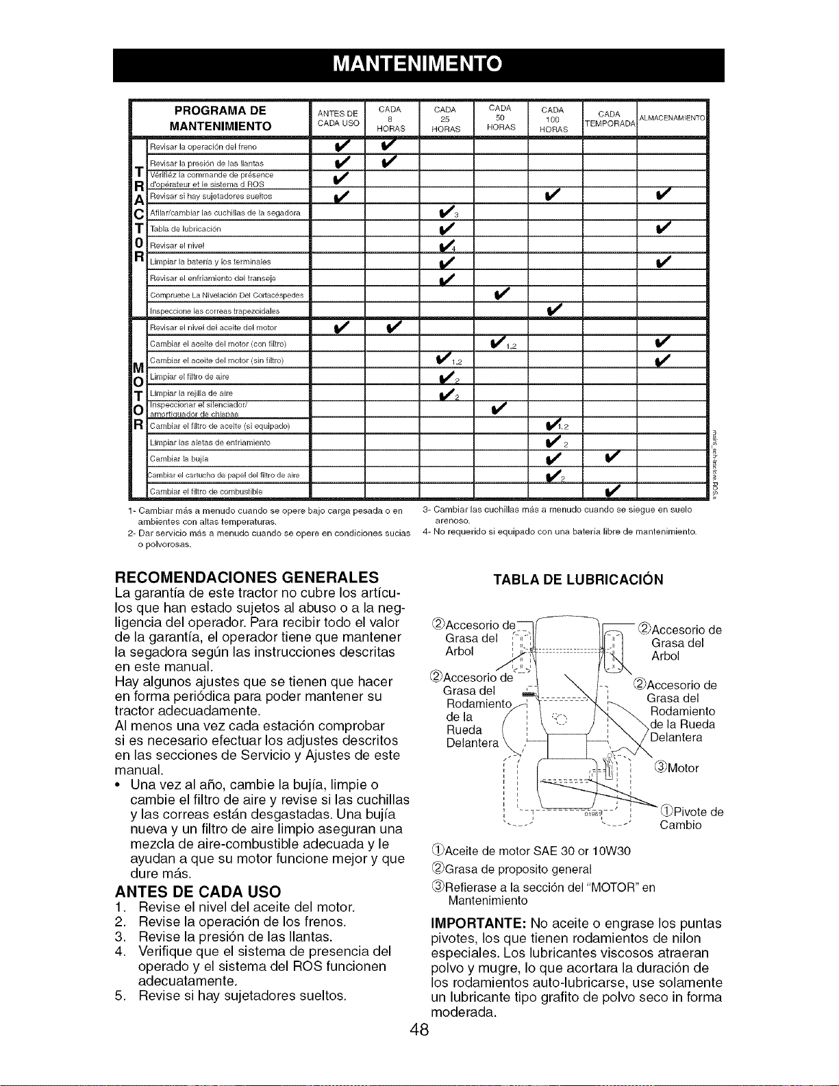
ANTES DE CADA CADA CADA CADA CADA ALMACENAMIENTC
CADA USO 8 25 50 100 TEMPORADA
HORAS HORAS HORAS HORAS
PROGRAMA DE
MANTENIMIENTO
Revisar la operaci6n del freno
Revisar la presi6n de las Ilantas
t Verifiez la commande de presence
R d'operateur et le sistema d ROS
A Revisar si hay sujetadores sueltos
C Afilar/cambiar las cuchillas de la segadora
t Tabla de lubdcaci6n
0 Revisar el nivel
R Limpiar la bateria y los terminales
Revisar el enfriamiento del transeje
Compruebe La Nivelaci6n Del Cortac#spedes
-- Inspeccione las correas trapezoidales
Revisar el nivel del aceite del motor
Cambiar el aceite del motor (con filtro)
M Cambiar el aceite del motor (sin filtro)
O Limpiar el filtro de aire
t Limpiar la rejilla de aire
Inspeccionar el silenciador/
O amortiauador de chisDas
a Cambiar el filtro de aceite (si equipado)
Limpiar las aletas de enfdamiento
Cambiar la bujia
Sambiar el cartucho de pape[ del filtro de aire
Cambiar el filtro de combustible
i/ v"
_d_'1,2
_1,2
v'
v'
_,2
1- Cambiar mrs a menudo cuando se opere bajo carga pesada o en 3- Cambiar las cuchillas mrs a menudo cuando se siegue en suelo
ambientes con altas temperaturas, arenoso.
2- Dar servicio mrs a menudo cuando se opere en condiciones sucias 4- No requerido si equipado con una bateria libre de mantenimiento.
o polvorosas.
RECOMENDAClONES GENERALES
La garantia de este tractor no cubre los articu-
los que han estado sujetos al abuso o a la neg-
ligencia del operador. Para recibir todo el valor
de la garantia, el operador tiene que mantener
la segadora segtJn las instrucciones descritas
en este manual.
Hay algunos ajustes que se tienen que hacer
en forma peri6dica para poder mantener su
tractor adecuadamente.
AI menos una vez cada estaci6n comprobar
si es necesario efectuar los adjustes descritos
en las secciones de Servicio y Ajustes de este
manual.
• Una vez al afio, cambie la bujia, limpie o
cambie el filtro de aire y revise si las cuchillas
y las correas est_.n desgastadas. Una bujia
nueva y un filtro de aire limpio aseguran una
mezcla de aire-combustible adecuada y le
ayudan a que su motor funcione mejor y que
dure m_ts.
ANTES DE CADA USO
1. Revise el nivel del aceite del motor.
2. Revise la operaci6n de los frenos.
3. Revise la presi6n de las Ilantas.
4. Verifique que el sistema de presencia del
operado y el sistema del ROS funcionen
adecuatamente.
5. Revise si hay sujetadores sueltos.
TABLA DE LUBRICACION
@Accesorio
Grasa del
Arbol
Grasa del
Rodamiento
de la
Rueda
@Accesorio de
Grasa del
Arbol
@Accesorio de
Grasa del
Rodamiento
_de la Rueda
Delantera
_3_Motor
_Pivote de
Cambio
_i_Aceite de motor SAE 30 or 10W30
@Grasa de proposito general
_.3_Refierasea la secci6n del "MOTOR" en
Mantenimiento
IMPORTANTE: No aceite o engrase los puntas
pivotes, los que tienen rodamientos de nilon
especiales. Los lubricantes viscosos atraeran
polvo y mugre, Io que acortara la duraci6n de
los rodamientos auto-lubricarse, use solamente
un lubricante tipo grafito de polvo seco in forma
moderada.
48
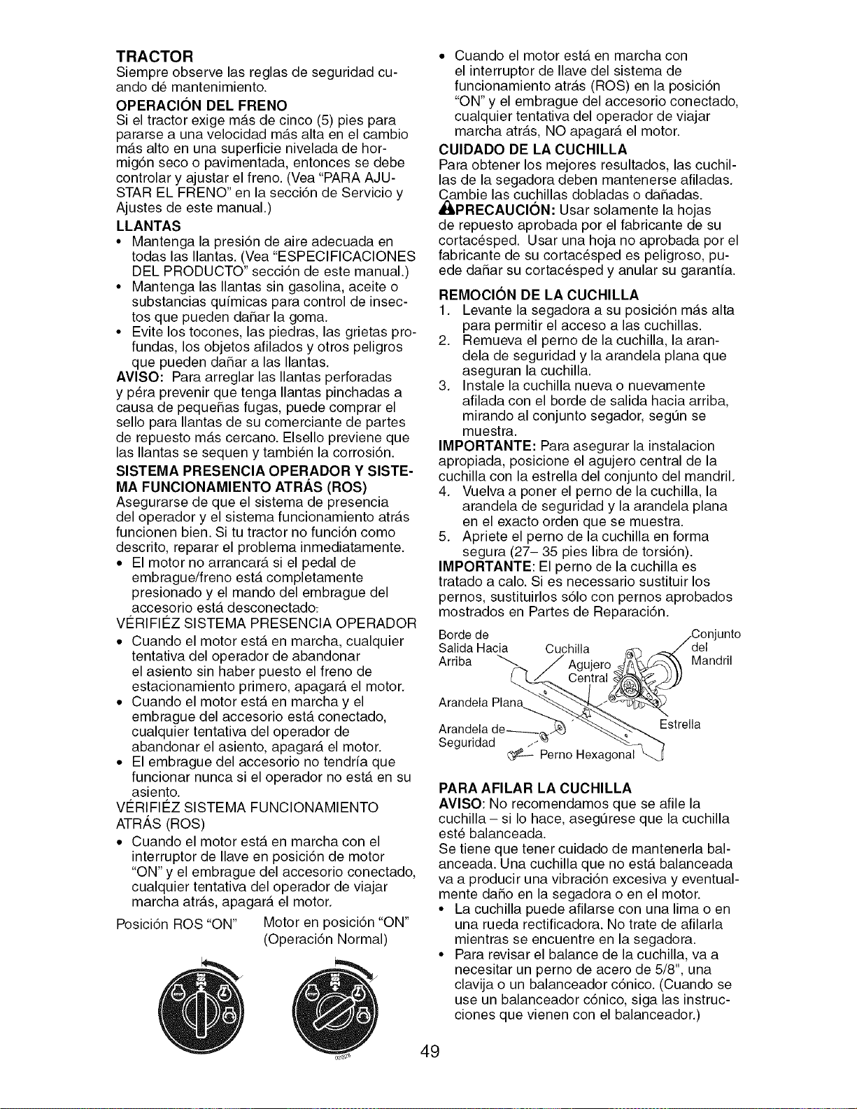
TRACTOR
Siempre observe las reglas de seguridad cu-
ando de mantenimiento.
OPERAClON DEL FRENO
Si el tractor exige m_.s de cinco (5) pies para
pararse a una velocidad m_ts alta en el cambio
m_.s alto en una superficie nivelada de hor-
mig6n seco o pavimentada, entonces se debe
controlar y ajustar el freno. (Vea "PARA AJU-
STAR EL FRENO" en la secci6n de Servicio y
Ajustes de este manual.)
LLANTAS
• Mantenga la presi6n de aire adecuada en
todas las Ilantas. (Vea "ESPECIFICACIONES
DEL PRODUCTO" secci6n de este manual.)
• Mantenga las Ilantas sin gasolina, aceite o
substancias qu[micas para control de insec-
tos que pueden daSar la goma.
• Evite los tocones, las piedras, las grietas pro-
fundas, los objetos afilados y otros peligros
que pueden daSar alas Ilantas.
AVISO: Para arreglar las Ilantas perforadas
y pera prevenir que tenga Ilantas pinchadas a
causa de pequeSas fugas, puede comprar el
sello para Ilantas de su comerciante de partes
de repuesto m_ts cercano. Elsello previene que
las Ilantas se sequen y tambien la corrosi6n.
SlSTEMA PRESENClA OPERADOR Y SlSTE-
MA FUNClONAMIENTO ATRAS (ROS)
Asegurarse de que el sistema de presencia
del operador y el sistema funcionamiento atr_.s
funcionen bien. Si tu tractor no funci6n como
descrito, reparar el problema inmediatamente.
• El motor no arrancar_, si el pedal de
embrague/freno ester completamente
presionado y el mando del embrague del
accesorio est,. desconectado_
VC:RIFII_Z SISTEMA PRESENCIA OPERADOR
• Cuando el motor est,. en marcha, cualquier
tentativa del operador de abandonar
el asiento sin haber puesto el freno de
estacionamiento primero, apagar_, el motor.
• Cuando el motor ester en marcha y el
embrague del accesorio est,. conectado,
cualquier tentativa del operador de
abandonar el asiento, apagar_t el motor.
• El embrague del accesorio no tendr[a que
funcionar nunca si el operador no est,. en su
asiento.
VC:RIFIC:Z SISTEMA FUNCIONAMIENTO
ATR,_,S (ROS)
• Cuando el motor ester en marcha con el
interruptor de Ilave en posici6n de motor
"ON" y el embrague del accesorio conectado,
cualquier tentativa del operador de viajar
marcha atr_ts, apagar_t el motor.
Posici6n ROS "ON" Motor en posici6n "ON"
(Operaci6n Normal)
• Cuando el motor ester en marcha con
el interruptor de Ilave del sistema de
funcionamiento atr_ts (ROS) en la posici6n
"ON" y el embrague del accesorio conectado,
cualquier tentativa del operador de viajar
marcha atr_.s, NO apagar_t el motor.
CUlDADO DE LA CUCHILLA
Para obtener los mejores resultados, las cuchil-
las de la segadora deben mantenerse afiladas.
Cambie las cuchillas dobladas o da_adas.
_PRECAUCl6N: Usar solamente la hojas
de repuesto aprobada por el fabricante de su
cortacesped. Usar una hoja no aprobada por el
fabricante de su cortacesped es peligroso, pu-
ede daSar su cortacesped y anular su garant[a.
REMOClON DE LA CUCHILLA
1. Levante la segadora a su posici6n m_ts alta
para permitir el acceso a las cuchillas.
2. Remueva el perno de la cuchilla, la aran-
dela de seguridad y la arandela plana que
aseguran la cuchilla.
3. Instale la cuchilla nueva o nuevamente
afilada con el borde de salida hacia arriba,
mirando al conjunto segador, segt3n se
muestra.
IMPORTANTE: Para asegurar la instalacion
apropiada, posicione el agujero central de la
cuchilla con la estrella del conjunto del mandril.
4. Vuelva a poner el perno de la cuchilla, la
arandela de seguridad y la arandela plana
en el exacto orden que se muestra.
5. Apriete el perno de la cuchilla en forma
segura (27- 35 pies libra de torsi6n).
IMPORTANTE: El perno de la cuchilla es
tratado a calo. Si es necessario sustituir los
pernos, sustituirlos s61o con pernos aprobados
mostrados en Partes de Reparaci6n.
Borde de unto
Salida Hacia Cuchilla del
Arriba _ Agujero Mandril
Central
Arandela Plana
Arandela de-----_._ Estrella
Seguridad /_
Perno Hexagonal
PARA AFILAR LA CUCHILLA
AVISO: No recomendamos que se afile la
cuchilla - si Io hace, asegt3rese que la cuchilla
este balanceada.
Se tiene que tener cuidado de mantenerla bal-
anceada. Una cuchilla que no ester balanceada
va a producir una vibraci6n excesiva y eventual-
mente da_o en la segadora o en el motor.
• La cuchilla puede afilarse con una lima o en
una rueda rectificadora. No trate de afilarla
mientras se encuentre en la segadora.
• Para revisar el balance de la cuchilla, va a
necesitar un perno de acero de 5/8", una
clavija o un balanceador c6nico. (Cuando se
use un balanceador c6nico, siga las instruc-
clones que vienen con el balanceador.)
49
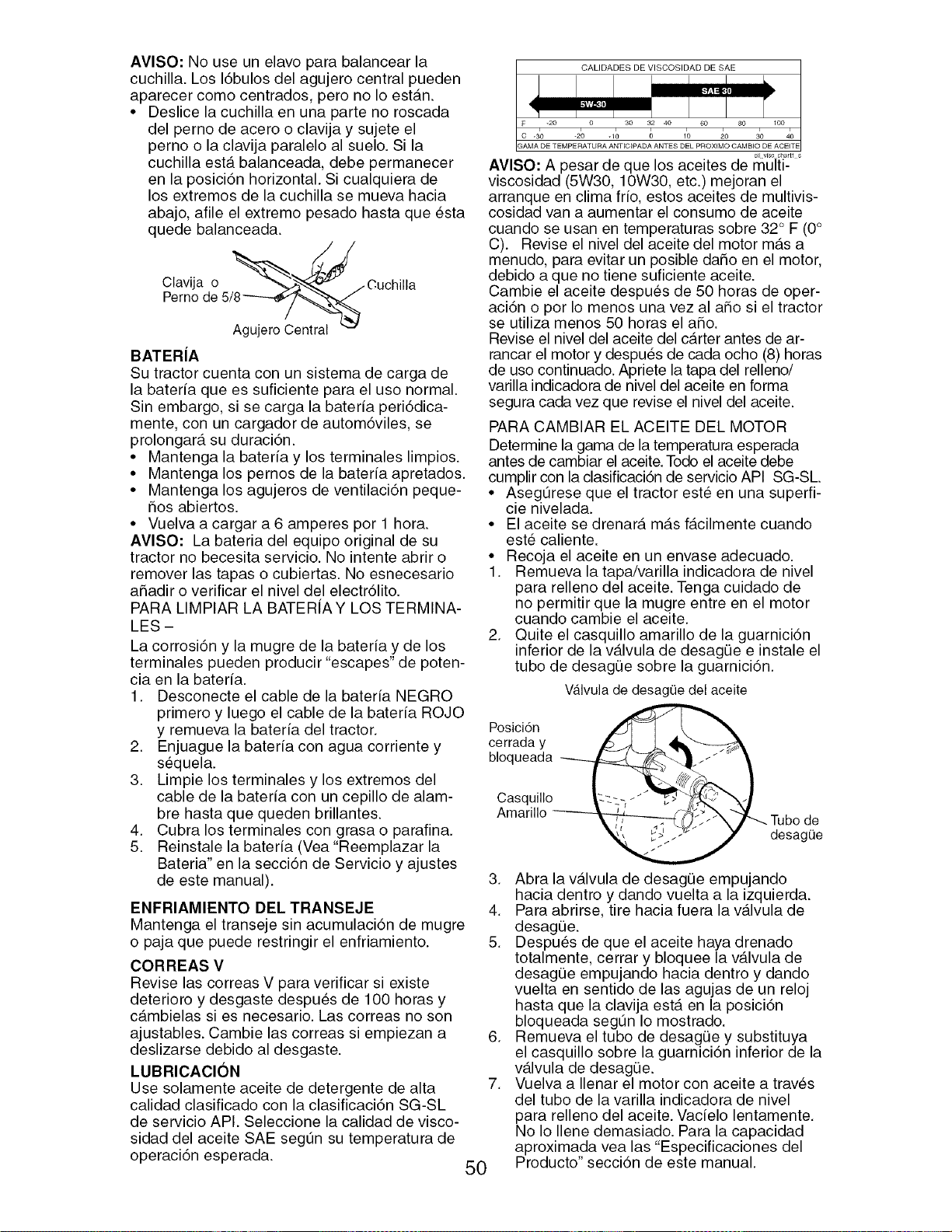
AVISO: No use un elavo para balancear la
cuchilla. Los 16bulos del agujero central pueden
aparecer como centrados, pero no Io est_.n.
• Deslice la cuchilla en una parte no roscada
del perno de acero o clavija y sujete el
perno o la clavija paralelo al suelo. Si la
cuchilla est,. balanceada, debe permanecer
en la posici6n horizontal. Si cualquiera de
los extremos de la cuchilla se mueva hacia
abajo, afile el extremo pesado hasta que _sta
quede balanceada.
Clavija o '_-j_" ...Cuchilla
Pernode 5/2_
BATERJA
Su tractor cuenta con un sistema de carga de
la bateria que es suficiente para el uso normal.
Sin embargo, si se carga la bateria peri6dica-
mente, con un cargador de autom6viles, se
prolongar_, su duraci6n.
• Mantenga la bateria y los terminales limpios.
• Mantenga los pernos de la bateria apretados.
• Mantenga los agujeros de ventilaci6n peque-
5os abiertos.
• Vuelva a cargar a 6 amperes por 1 hora.
AVlSO: La bateria del equipo original de su
tractor no becesita servicio. No intente abrir o
remover las tapas o cubiertas. No esnecesario
aSadir o verificar el nivel del electr61ito.
PARA LIMPIAR LA BATERiA Y LOS TERMINA-
LES -
La corrosi6n y la mugre de la bateria y de los
terminales pueden producir"escapes" de poten-
cia en la bateria.
1. Desconecte el cable de la bateria NEGRO
primero y luego el cable de la bateria ROJO
y remueva la bateria del tractor.
2. Enjuague la bateria con agua corriente y
sequela.
3. Limpie los terminales y los extremos del
cable de la bateria con un cepillo de alam-
bre hasta que queden brillantes.
4. Cubra los terminales con grasa o parafina.
5. Reinstale la bateria (Vea"Reemplazar la
Bateria" en la secci6n de Servicio y ajustes
de este manual).
ENFRIAMIENTO DEL TRANSEJE
Mantenga el transeje sin acumulaci6n de mugre
o paja que puecle restringir el enfriamiento.
CORREAS V
Revise las correas V para verificar si existe
deterioro y desgaste despu_s de 100 horas y
c_.mbielas si es necesario. Las correas no son
ajustables. Cambie las correas si empiezan a
deslizarse debido al desgaste.
LUBRICAClON
Use solamente aceite de detergente de alta
calidad clasificado con la clasificaci6n SG-SL
de servicio API. Seleccione la calidad de visco-
sidad del aceite SAE segOn su temperatura de
operaci6n esperada.
CALIDADES DE VISCOSIDAD DE SAE
o_Lv_c chart1 s
AVlSO: A pesar de que los aceites de multi-
viscosidad (5W30, 10W30, etc.) mejoran el
arranque en clima frio, estos aceites de multivis-
cosidad van a aumentar el consumo de aceite
cuando se usan en temperaturas sobre 32° F (0°
C). Revise el nivel del aceite del motor m_.s a
menudo, para evitar un posible daSo en el motor,
debido a que no tiene suficiente aceite.
Cambie el aceite despues de 50 horas de oper-
aci6n o por Io menos una vez al aSo si el tractor
se utiliza menos 50 horas el aSo.
Revise el nivel del aceite del c_.rter antes de ar-
rancar el motor y despu_s de cada ocho (8) horas
de uso continuado. Apriete la tapa del relleno/
varilla indicadora de nivel del aceite en forma
segura cada vez que revise el nivel del aceite.
PARA CAMBIAR EL ACEITE DEL MOTOR
Determine la gama de la temperatura esperada
antes de cambiar el aceite. Todo el aceite debe
cumplir con la clasificaci6n de servicio API SG-SL
• Asegt3rese que el tractor este en una superfi-
cie nivelada.
• El aceite se drenar_, m_.s f_.cilmente cuando
est_ caliente.
• Recoja el aceite en un envase adecuado.
1. Remueva la tapa/varilla indicadora de nivel
para relleno del aceite. Tenga cuidado de
no permitir que la mugre entre en el motor
cuando cambie el aceite.
2. Quite el casquillo amarillo de la guarnici6n
inferior de la v_.lvula de desag0e e instale el
tubo de desagQe sobre la guarnici6n.
Valvulade desagOedel aceite
Posici6n
cerrada y
bloqueada
Casquillo
Amarillo
Tubo de
desagee
50
3. Abra la v_.lvula de desagQe empujando
hacia dentro y dando vuelta a la izquierda.
4. Para abrirse, tire hacia fuera la v_.lvula de
desagQe.
5. Despues de que el aceite haya drenado
totalmente, cerrar y bloquee la v_.lvula de
desagQe empujando hacia dentro y dando
vuelta en sentido de las agujas de un reloj
hasta que la clavija ester en la posici6n
bloqueada segt3n Io mostrado.
6. Remueva el tubo de desagQe y substituya
el casquillo sobre la guarnici6n inferior de la
v_tlvula de desagQe.
7. Vuelva a Ilenar el motor con aceite a traves
del tubo de la varilla indicadora de nivel
para relleno del aceite. Vacielo lentamente.
No Io Ilene demasiado. Para la capacidad
aproximada vea las "Especificaciones del
Producto" secci6n de este manual.
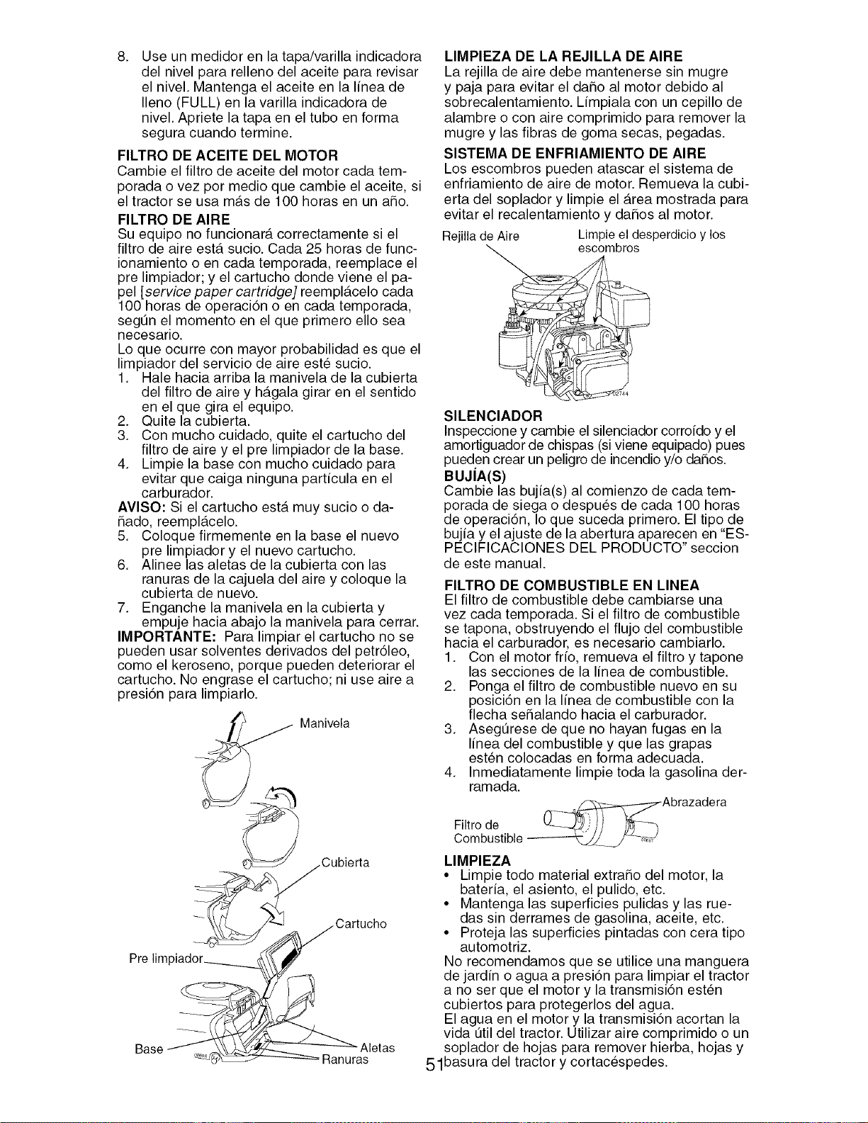
.
Use un medidor en la tapa/varilla indicadora
del nivel para relleno del aceite para revisar
el nivel. Mantenga el aceite en la linea de
Ileno (FULL) en la varilla indicadora de
nivel. Apriete la tapa en el tubo en forma
segura cuando termine.
FILTRO DE ACEITE DEL MOTOR
Cambie el filtro de aceite del motor cada tem-
porada ovez por medio que cambie el aceite, si
el tractor se usa m_.s de 100 horas en un aho.
FILTRO DE AIRE
Su equipo no funcionar_t correctamente si el
filtro de aire est,. sucio. Cada 25 horas de func-
ionamiento o en cada temporada, reemplace el
pre limpiador; y el cartucho donde viene el pa-
pel [service paper cartridge] reempl_tcelo cada
100 horas de operaci6n o en cada temporada,
segt3n el momento en el que primero ello sea
necesario.
Lo que ocurre con mayor probabilidad es que el
limpiador del servicio de aire est_ sucio.
1. Hale hacia arriba la manivela de la cubierta
del filtro de aire y h_.gala girar en el sentido
en el que gira el equipo.
2. Quite la cubierta.
3. Con mucho cuidado, quite el cartucho del
filtro de aire y el pre limpiador de la base.
4. Limpie la base con mucho cuidado para
evitar que caiga ninguna particula en el
carburador.
AVlSO" Si el cartucho est,. muy sucio o da-
_ado, reempl_.celo.
5. Coloque firmemente en la base el nuevo
pre limpiador y el nuevo cartucho.
6. Alinee las aletas de la cubierta con las
ranuras de la cajuela del aire y coloque la
cubierta de nuevo.
7. Enganche la manivela en la cubierta y
empuje hacia abajo la manivela para cerrar.
IMPORTANTE: Para limpiar el cartucho no se
pueden usar solventes derivados del petr61eo,
como el keroseno, porque pueden deteriorar el
cartucho. No engrase el cartucho; ni use aire a
presi6n para limpiarlo.
Manivela
Cubierta
Prelim
Base Aletas
= Ranuras
LIMPIEZA DE LA REJILLA DE AIRE
La rejilla de aire debe mantenerse sin mugre
y paja para evitar el daho al motor debido al
sobrecalentamiento. Lfmpiala con un cepillo de
alambre o con aire comprimido para remover la
mugre y las fibras de goma secas, pegadas.
SlSTEMA DE ENFRIAMIENTO DE AIRE
Los escombros pueden atascar el sistema de
enfriamiento de aire de motor. Remueva la cubi-
erta del soplador y limpie el Area mostrada para
evitar el recalentamiento y daSos al motor.
Rejilla de Aire Limpie el desperdicio y los
escombros
SlLENClADOR
Inspeccione y cambie el silenciador corroido y el
amortiguador de chispas (si viene equipado) pues
pueden crear un peligro de incendio y/o da_os.
BUJJA(S)
Cambie las bujia(s) al comienzo de cada tem-
porada de siega o despues de cada 100 horas
de operaci6n, Io que suceda primero. El tipo de
bujia y el ajuste de la abertura aparecen en "ES-
PECIFICACIONES DEL PRODUCTO" seccion
de este manual.
FILTRO DE COMBUSTIBLE EN LINEA
El filtro de combustible debe cambiarse una
vez cada temporada. Si el filtro de combustible
se tapona, obstruyendo el flujo del combustible
hacia el carburador, es necesario cambiarlo.
1. Con el motor frio, remueva el filtro y tapone
las secciones de la linea de combustible.
2. Ponga el filtro de combustible nuevo en su
posici6n en la linea de combustible con la
flecha seSalando hacia el carburador.
3. Asegt3rese de que no hayan fugas en la
linea del combustible y que las grapas
esten colocadas en forma adecuada.
4. Inmediatamente limpie toda la gasolina der-
ramada.
Abrazadera
Filtro de -_
Combustible
LIMPIEZA
• Limpie todo material extra_o del motor, la
bateria, el asiento, el pulido, etc.
• Mantenga las superficies pulidas y las rue-
das sin derrames de gasolina, aceite, etc.
• Proteja las superficies pintadas con cera tipo
automotriz.
No recomendamos que se utilice una manguera
de jardin o agua a presi6n para limpiar el tractor
a no ser que el motor y la transmisi6n est_n
cubiertos para protegerlos del agua.
El agua en el motor y la transmisi6n acortan la
vida tJtil del tractor. Utilizar aire comprimido o un
soplador de hojas para remover hierba, hojas y
51basura del tractor y cortac_spedes.
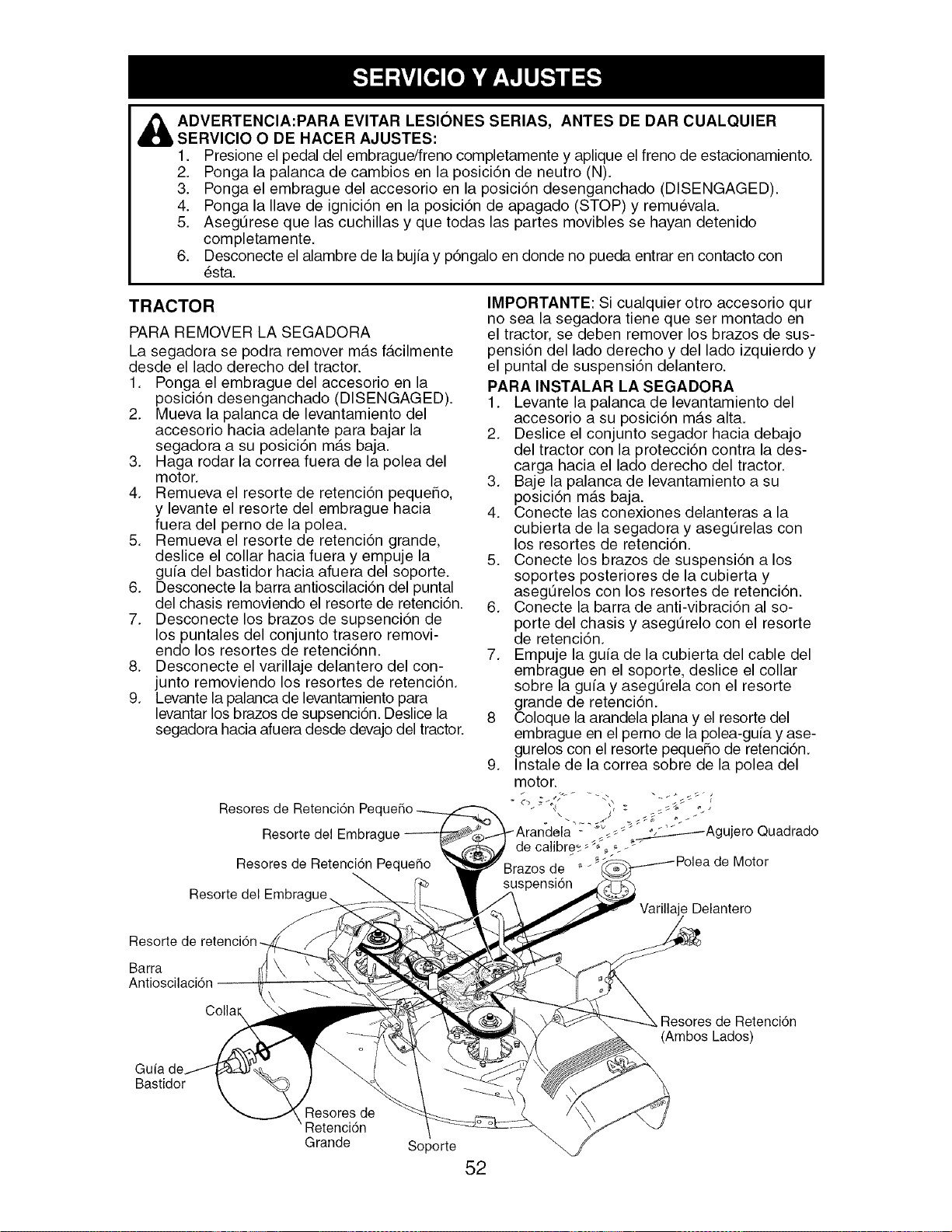
ADVERTENCIA:PARA EVITAR LESIONES SERIAS, ANTES DE DAR CUALQUIER
SERVICIO O DE HACER AJUSTES:
1. Presione el pedal del embrague/freno completamente y aplique el freno de estacionamiento.
2. Ponga la palanca de cambios en la posici6n de neutro (N).
3. Ponga el embrague del accesorio en la posici6n desenganchado (DISENGAGED).
4. Ponga la Ilave de ignici6n en la posici6n de apagado (STOP) y remuevala.
5. AsegtJrese que las cuchillas y que todas las partes movibles se hayan detenido
completamente.
6. Desconecte el alambre de la bujia y p6ngalo en donde no pueda entrar en contacto con
_sta.
TRACTOR
PARA REMOVER LA SEGADORA
La segadora se podra remover m_.s f_.cilmente
desde el lado derecho del tractor.
1. Ponga el embrague del accesorio en la
posici6n desenganchado (DISENGAGED).
2. Mueva la palanca de levantamiento del
accesorio hacia adelante para bajar la
segadora a su posici6n m_.s baja.
3. Haga rodar la correa fuera de la polea del
motor.
4. Remueva el resorte de retenci6n pequeSo,
y levante el resorte del embrague hacia
fuera del perno de la polea.
5. Remueva el resorte de retenci6n grande,
deslice el collar hacia fuera y empuje la
guia del bastidor hacia afuera del soporte.
6. Desconecte la barra antioscilaci6n del puntal
del chasis removiendo el resorte de retenci6n.
7. Desconecte los brazos de supsenci6n de
los puntales del conjunto trasero removi-
endo los resortes de retenci6nn.
8. Desconecte el varillaje delantero del con-
junto removiendo los resortes de retenci6n.
9. Levante la palanca de levantamiento para
levantar los brazos de supsenci6n. Deslice la
segadora hacia afuera desde devajo del tractor.
Resores de Retenci6n Peq
Resorte del Embra{
Resores de Retenci6n Pequefio
IMPORTANTE: Si cualquier otto accesorio qur
no sea la segadora tiene que ser montado en
el tractor, se deben remover los brazos de sus-
pensi6n del lado derecho y del lado izquierdo y
el puntal de suspensi6n delantero.
PARA INSTALAR LA SEGADORA
1. Levante la palanca de levantamiento del
accesorio a su posici6n m_.s alta.
2. Deslice el conjunto segador hacia debajo
del tractor con la protecci6n contra la des-
carga hacia el lado derecho del tractor.
3. Baje la palanca de levantamiento a su
posici6n m_.s baja.
4. Conecte las conexiones delanteras a la
cubierta de la segadora y asegQrelas con
los resortes de retenci6n.
5. Conecte los brazos de suspensi6n a los
soportes posteriores de la cubierta y
asegQrelos con los resortes de retenci6n.
6. Conecte la barra de anti-vibraci6n al so-
porte del chasis y asegQrelo con el resorte
de retenci6n.
7. Empuje la guia de la cubierta del cable del
embrague en el soporte, deslice el collar
sobre la guia y asegQrela con el resorte
grande de retenci6n.
8 Coloque la arandela plana y el resorte del
embrague en el perno de la polea-guia y ase-
gurelos con el resorte pequeSo de retenci6n.
9. Instale de la correa sobre de la polea del
motor.
Aranctela ::"-_'C¢¢¢_Agujero Quadrado
de cahbre_; , _ £ _
de Motor
Resorte de
Barra
Delantero
Guia
Bastidor
Colla_
Resores de
Retenci6n
Grande
Soporte
52
Resores de Retenci6n
(,
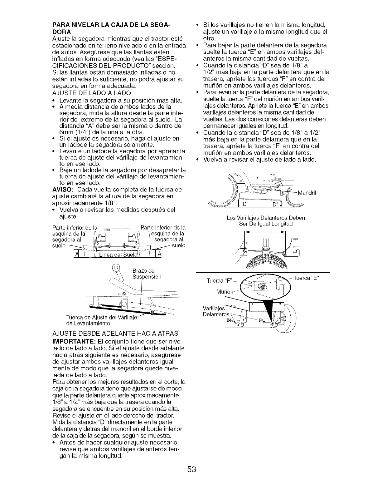
PARA NIVELAR LA CAJA DE LA SEGA-
DORA
Ajuste la segadora mientras que el tractor este
estacionado en terreno nivelado o en la entrada
de autos. Aseg_rese que las Ilantas est6n
infladas en forma adecuada (vea las "ESPE-
CIFICACIONES DEL PRODUCTO" seccion.
Si las Ilantas est_.n demasiado infladas o no
est_.n infladas Io suficiente, no podr_, ajustar su
segadora en forma adecuada.
AJUSTE DE LADO A LADO
• Levante la segadora a su posici6n m_.s alta.
• A media distancia de ambos lados de la
segadora, mida la altura desde la parte infe-
rior del extremo de la segadora al suelo. La
distancia "A" debe ser la misma o dentro de
6mm (1/4") de la una a la otra.
• Si el ajuste es necesario, haga el ajuste en
un ladode la segadora solamente.
• Levante un ladode la segadora por apretar la
tuerca de ajuste del v_.rillaje de levantamien-
to en ese lado.
• Baje un ladode la segadora por desapretar la
tuerca de ajuste del v_.rillaje de levantamien-
to en ese lado.
AVISO: Cada vuelta completa de la tuerca de
ajuste cambiar_, la altura de la segadora en
aproximadamente 1/8".
• Vuelva a revisar las medidas despu6s del
ajuste.
Parte inferior de la _ Parte inferior de la
esquina de I_--_ _'_ _ _--_ esquina de la
segadora al_ I_==::::::::=_--_,_i / segadora al
sue o 4- - 4 _/sue o
• Si los varillajes no tienen la misma Iongitud,
ajuste un varillaje a la misma Iongitud que el
otto.
• Para bajar la parte delantera de la segadora
suelte la tuerca "E" en ambos varillajes del-
anteros la misma cantidad de vueltas.
• Cuando la distancia"D" sea de 1/8" a
1/2" m_.s baja en la parte delantera queen la
trasera, apriete las tuercas "F" en contra del
mu56n en ambos varillajes delanteros.
• Para levantar la parte delantera de la segadora,
suelte la tuerca "F" del mu56n en ambos varil-
lajes delanteros. Apriete la tuerca "E" en ambos
varillajes delanteros la misma cantidad de
vueltas. Las dos conexiones delanteras deben
permanecer iguales en Iongitud.
• Cuando la distancia"D" sea de 1/8" a 1/2"
m_.s baja en la parte delantera queen la
trasera, apriete la tuerca "F" en contra del
mu56n en ambos varillajes delanteros.
• Vuelva a revisar el ajuste de lado a lado.
Los Varillajes Delanteros Deben
Ser De Igual Longitud
Brazo de
Suspensi6n
Tuerca de Ajuste del Va.rilla
de Levantamiento
AJUSTE DESDE ADELANTE HACIA ATR,_,S
IMPORTANTE: El conjunto tiene que ser nive-
lado de lado a lado. Si el ajuste desde adelante
hacia atr_.s siguiente es necesario, asegurese
de ajustar ambos varillajes delanteros igual-
mente de modo que la segadora quede nive-
lada de lado a lado.
Para obtener los mejores resultados en el corte, la
caja de la segadora tiene que ajustarse de modo
que la parte delantera quede aproximadamente
1/8" a 1/2" m4ts baja que la trasera cuando la
segadora se encuentre en su posici6n m_.s alta.
Revise el ajuste en el lado derecho del tractor.
Mida la distancia "D" directamente en la parte
delantera y detr_.s del mandril en el borde inferior
de la caja de la segadora, segt3n se muestra.
• Antes de hacer cualquier ajuste necesario,
revise que ambos varillajes delanteros ten-
gan la misma Iongitud.
Tuerca"F: ---___Tuerca "E"
Delanter_l_,S
53
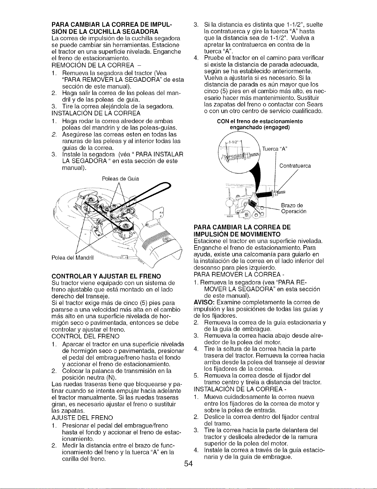
PARA CAMBIAR LA CORREA DE IMPUL-
SION DE LA CUCHILLA SEGADORA
La correa de impulsi6n de la cuchilla segadora
se puede cambiar sin herramientas. Estacione
el tractor en una superficie nivelada. Enganche
el freno de estacionamiento.
REMOCION DE LA CORREA -
1. Remueva la segadora del tractor (Vea
"PARA REMOVER LA SEGADORA" de esta
secci6n de este manual).
2. Haga salir la correa de las poleas del man-
dril y de las poleas de guia.
3. Tire la correa alej_.ndola de la segadora.
INSTALAClON DE LA CORREA
1. Haga rodar la correa alredeor de ambas
poleas del mandrin y de las poleas-guias.
2. Asegt3rese las correas esten en todas las
ranuras de las peleas y al interior todas las
guias de la correa.
3. Instale la segadora (vea" PARA INSTALAR
LA SEGADORA" en esta secci6n de este
manual).
Poleas de Guia
.
.
Si la distancia es distinta que 1-1/2", suelte
la contratuerca y gire la tuerca "A" hasta
que la distancia sea de 1-1/2". Vuelva a
apretar la contratuerca en contra de la
tuerca "A".
Pruebe el tractor en el camino para verificar
si existe la distancia de parada adecuada,
segt3n se ha establecido anteriormente.
Vuelva a ajustarla si es necesario. Si la
distancia de parada es at3n mayor que los
cinco (5) pies en el cambio m_.s alto, es nec-
esario hacer m_.s mantenimiento. Sustituir
las zapatas del freno o contactar con Sears
o con un otro centro de servicio cualificado.
CON el freno de estacionamiento
enganchado (engaged)
_ Tuerca "A"
Contratuerca
Polea del Mandril
CONTROLAR Y AJUSTAR EL FRENO
Su tractor viene equipado con un sistema de
freno ajustable que est,. montado en el lado
derecho clel transeje.
Si el tractor exige m_.s de cinco (5) pies para
pararse a una velocidad m_.s alta en el cambio
m_.s alto en una superficie nivelada de hor-
mig6n seco o pavimentada, entonces se debe
controlar y ajustar el freno.
CONTROL DEL FRENO
1. Aparcar el tractor en una superficie nivelada
de hormig6n seco o pavimentada, presionar
el pedal del embrague/freno hasta el fondo
y accionar el freno de estacionamiento.
2. Colocar la palanca de transmisi6n en la
posici6n neutra (N).
Las ruedas traseras tiene que bloquearse y pa-
tinar cuando se intenta empujar hacia adelante
el tractor manualmente. Si las ruedas traseras
giran, es necesario ajustar el freno o sustituir
las zapatas.
AJUSTE DEL FRENO
1. Presionar el pedal del embrague/freno
hasta el fondo y accionar el freno de estac-
ionamiento.
2. Medir la distancia entre el brazo de func-
ionamiento del freno y la tuerca "A" en la
carilla del freno.
Brazo de
)eraci6n
PARA CAMBIAR LA CORREA DE
IMPULSION DE MOVIMIENTO
Estacione el tractor en una superficie nivelada.
Enganche el freno de estacionamiento. Para
ayuda, existe una calcomania para guiarlo en
la instalaci6n de la correa en el lado inferior del
descanso para pies izquierdo.
PARA REMOVER LA CORREA -
1. Remueva la segadora (vea "PARA RE-
MOVER LA SEGADORA" en esta secci6n
de este manual).
AVlSO: Examine completamente la correa de
impulsi6n y las posici6nes de todas las guias y
de los fijadores.
2. Remueva la correa de la guia estacionaria y
de la guia de embrague.
3. Remueva la correa hacia abajo desde alre-
dedor de la polea del motor.
4. Tire la soltura de la correa hacia la parte
trasera del tractor. Remueva la correa hacia
arriba desde la polea del transeje al desviar
los fijadores de la correa.
5. Remueva la correa desde el fijador del
tramo centro y tirela a distancia del tractor.
INSTALACION DE LA CORREA -
1. Mueva cuidadosamente la correa nueva
entre los fijadores de la correa de motor y
sobre la polea de entrada.
2. Deslice la correa dentro del fijador central
del tramo.
3. Tire la correa hacia la parte delantera del
tractor y deslicela alrededor de la ramura
superior de la polea del motor.
Instale la correa a traves de la guia estacio-
naria y de la guia de embrague.
.
54
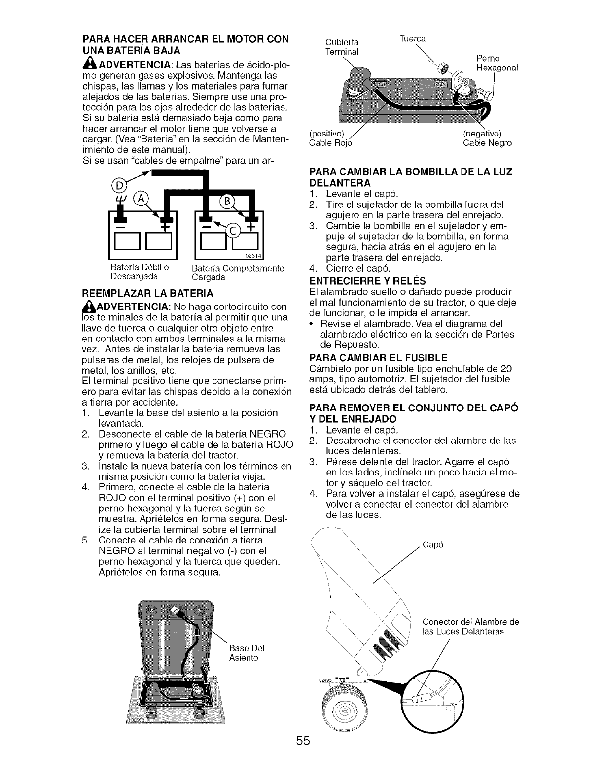
PARA HACER ARRANCAR EL MOTOR CON
UNA BATERIA BAJA
_I_ADVERTENCIA: Las baterfas de _.cido-plo-
mo generan gases explosivos. Mantenga las
chispas, las llamas y los materiales para fumar
alejados de las baterfas. Siempre use una pro-
tecci6n para los ojos alrededor de las baterfas.
Si su baterfa est,. demasiado baja como para
hacer arrancar el motor tiene que volverse a
cargar. (Vea "Baterfa" en la secci6n de Manten-
imiento de este manual).
Si se usan "cables de empalme" para un ar-
DD
02614
Bateria Debil o Bateria Completamente
Descargada Cargada
REEMPLAZAR LA BATERIA
I_ADVERTENClA: No haga cortocircuito con
os terminales de la baterfa al permitir que una
Ilave de tuerca o cualquier otro objeto entre
en contacto con ambos terminales a la misma
vez. Antes de instalar la baterfa remueva las
pulseras de metal, los relojes de pulsera de
metal, los anillos, etc.
El terminal positivo tiene que conectarse prim-
ero para evitar las chispas debido a la conexi6n
a tierra por accidente.
1. Levante la base del asiento a la posici6n
levantada.
2. Desconecte el cable de la bateria NEGRO
primero y luego el cable de la bateria ROJO
y remueva la bateria del tractor.
3. Instale la nueva bateria con los t_rminos en
misma posici6n como la bateria vieja.
4. Primero, conecte el cable de la bateria
ROJO con el terminal positivo (+) con el
perno hexagonal y la tuerca segQn se
muestra. Apri_telos en forma segura. Desl-
ize la cubierta terminal sobre el terminal
5. Conecte el cable de conexi6n a tierra
NEGRO al terminal negativo (-) con el
perno hexagonal y la tuerca que queden.
Aprietelos en forma segura.
Base Del
Asiento
Cubierta Tuerca
Terminal _.. Perno
"@. Hexagonal
(positivo) (negativo)
Cable Rojo Cable Negro
PARA CAMBIAR LA BOMBILLA DE LA LUZ
DELANTERA
1. Levante el cap6.
2. Tire el sujetador de la bombilla fuera del
agujero en la parte trasera del enrejado.
3. Cambie la bombilla en el sujetador y em-
puje el sujetador de la bombilla, en forma
segura, hacia atr_.s en el agujero en la
parte trasera del enrejado.
4. Cierre el cap6.
ENTREClERRE Y RELI_S
El alambrado suelto o daSado puede producir
el mal funcionamiento de su tractor, o que deje
de funcionar, o le impida el arrancar.
• Revise el alambrado. Vea el diagrama del
alambrado el_ctrico en la secci6n de Partes
de Repuesto.
PARA CAMBIAR EL FUSIBLE
C_.mbielo por un fusible tipo enchufable de 20
amps, tipo automotriz. El sujetador del fusible
est,. ubicado detr_.s del tablero.
PARA REMOVER EL CONJUNTO DEL CAPO
Y DEL ENREJADO
1. Levante el cap6.
2. Desabroche el conector del alambre de las
luces delanteras.
3. P_.rese delante del tractor. Agarre el cap6
en los lados, inclfnelo un poco hacia el mo-
tor y s_.quelo del tractor.
4. Para volver a instalar el cap6, aseg_rese de
volver a conectar el conector del alambre
de las luces.
55
Cap6
\\ _'_
Con eCc °r,dGe', '1 barede
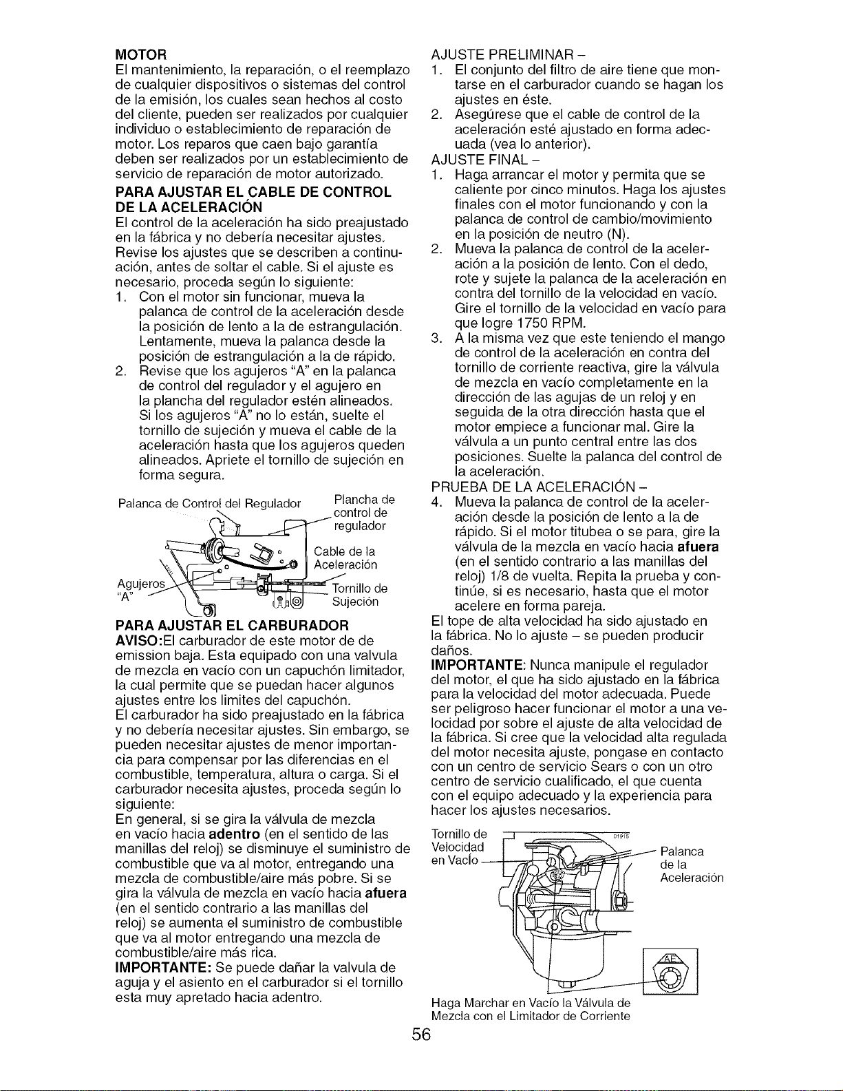
MOTOR
El mantenimiento, la reparaci6n, o el reemplazo
de cualquier dispositivos o sistemas del control
de la emisi6n, los cuales seen hechos al costo
del cliente, pueden ser realizados por cualquier
individuo o establecimiento de reparaci6n de
motor. Los reparos que caen bajo garantia
deben ser realizados por un establecimiento de
servicio de reparaci6n de motor autorizado.
PARA AJUSTAR EL CABLE DE CONTROL
DE LA ACELERAClON
El control de la aceleraci6n ha sido preajustado
en la f_tbrica y no deberia necesitar ajustes.
Revise los ajustes que se describen a continu-
aci6n, antes de soltar el cable. Si el ajuste es
necesario, proceda segt3n Io siguiente:
1. Con el motor sin funcionar, mueva la
palanca de control de la aceleraci6n desde
la posici6n de lento ala de estrangulaci6n.
Lentamente, mueva la palanca desde la
posici6n de estrangulaci6n ala de r_.pido.
2. Revise que los agujeros "A" en la palanca
de control del regulador y el agujero en
la plancha del regulador esten alineados.
Si los agujeros "A" no Io est,.n, suelte el
tornillo de sujeci6n y mueva el cable de la
aceleraci6n haste que los agujeros queden
alineados. Apriete el tornillo de sujeci6n en
forma segura.
Plancha de
Palanca de Controlde\ I Regulador control de
_ ,_"'_ ._C:_ regulador
_/(_ _._° I Cable de la
"%_._____ Ac_racidn
Ag,ujero_ _ Tornillode
A _ _ _."_ '_ _d3@L._----Sujeci6n
PARA AJUSTAR EL CARBURADOR
AVISO:EI carburador de este motor de de
emission baja. Esta equipado con una valvula
de mezcla en vado con un capuch6n limitador,
la cual permite que se puedan hacer algunos
ajustes entre los limites del capuch6n.
El carburador ha sido preajustado en la f_tbrica
y no deberfa necesitar ajustes. Sin embargo, se
pueden necesitar ajustes de menor importan-
cia pare compensar por las diferencias en el
combustible, temperature, altura o carga. Si el
carburador necesita ajustes, proceda segt3n Io
siguiente:
En general, si se gira la v_tlvula de mezcla
en vado hacia adentro (en el sentido de las
manillas del reloj) se disminuye el suministro de
combustible que vaal motor, entregando una
mezcla de combustible/aire m_.s pobre. Si se
gira la v_tlvula de mezcla en vacfo hacia afuera
(en el sentido contrario alas manillas del
reloj) se aumenta el suministro de combustible
que vaal motor entregando una mezcla de
combustible/aire m_ts rice.
IMPORTANTE: Se puede daSar la valvula de
aguja y el asiento en el carburador si el tornillo
esta muy apretado hacia adentro.
AJUSTE PRELIMINAR -
1. El conjunto del filtro de aire tiene que mon-
terse en el carburador cuando se hagen los
ajustes en este.
2. Asegt3rese que el cable de control de la
aceleraci6n est_ ajustado en forma adec-
uada (vea Io anterior).
AJUSTE FINAL-
1. Haga arrancar el motor y permita que se
caliente por cinco minutos. Haga los ajustes
finales con el motor funcionando y con la
palanca de control de cambio/movimiento
en la posici6n de neutro (N).
2. Mueva la palanca de control de la aceler-
aci6n ala posici6n de lento. Con el dedo,
rote y sujete la palanca de la aceleraci6n en
contra del tornillo de la velocidad en vacfo.
Gire el tornillo de la velocidad en vacfo pare
que Iogre 1750 RPM.
3. Ala misma vez que este teniendo el mango
de control de la aceleraci6n en contra del
tornillo de corriente reactive, gire la v_tlvula
de mezcla en vacfo completamente en la
direcci6n de las agujas de un reloj yen
seguida de la otra direcci6n haste que el
motor empiece a funcionar mal. Gire la
v_.lvula a un punto central entre las dos
posiciones. Suelte la palanca del control de
la aceleraci6n.
PRUEBA DE LA ACELERACION -
4. Mueva la palanca de control de la aceler-
aci6n desde la posici6n de lento ala de
r_.pido. Si el motor titubea o se pare, gire la
v_tlvula de la mezcla en vado hacia afuera
(en el sentido contrario a las manillas del
reloj) 1/8 de vuelta. Repita la prueba y con-
tint3e, si es necesario, haste que el motor
acelere en forma pareja.
El tope de alta velocidad ha sido ajustado en
la f_tbrica. No Io ajuste - se pueden producir
dahos.
IMPORTANTE: Nunca manipule el regulador
del motor, el que ha sido ajustado en la f_.brica
pare la velocidad del motor adecuada. Puede
ser peligroso hacer funcionar el motor a una ve-
Iocidad por sobre el ajuste de alta velocidad de
la f_.brica. Si cree que la velocidad alta regulada
del motor necesita ajuste, pongase en contacto
con un centro de servicio Sears o con un otro
centro de servicio cualificado, el que cuenta
con el equipo adecuado y la experiencia pare
hacer los ajustes necesarios.
Tornillo de
Velocidad
en
Palanca
de la
Aceleracidn
Haga Marcher enVacfo la Va.lvulade
Mezcla con el Limitadorde Corriente
56
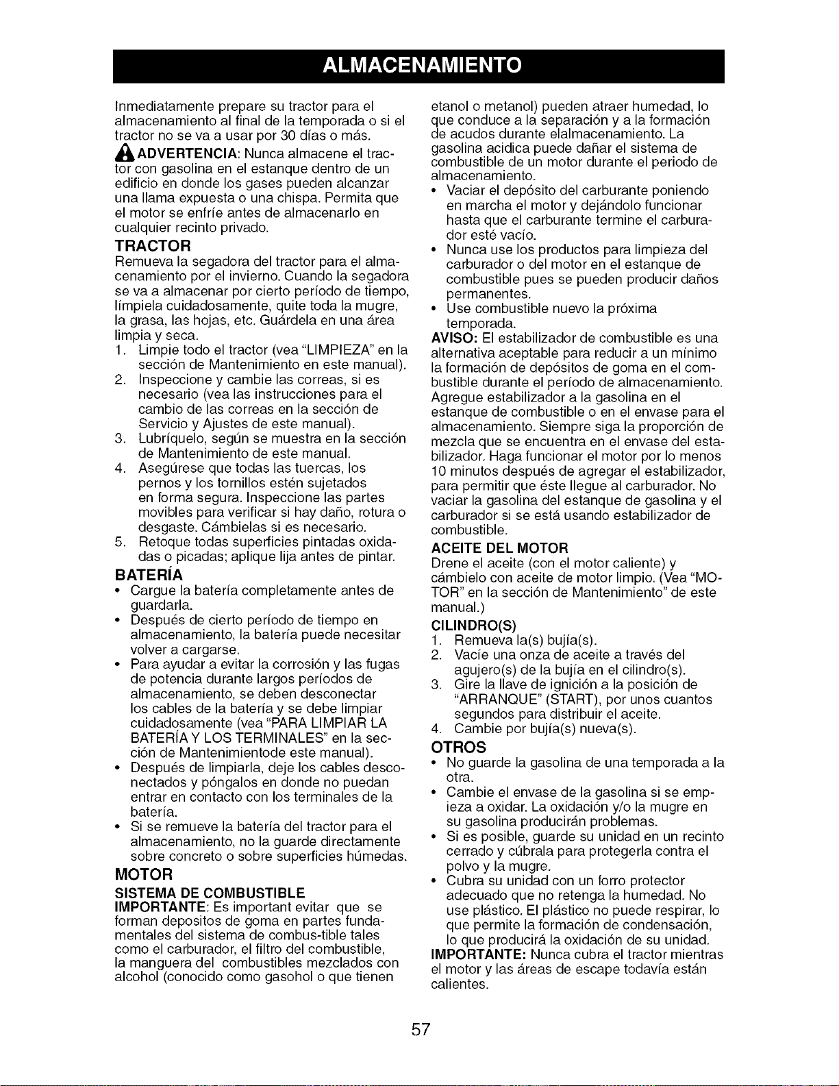
Inmediatamente prepare su tractor para el
almacenamiento al final de la temporada o si el
tractor no se va a usar por 30 dias o m_.s.
_ADVERTENClA: Nunca almacene el trac-
tor con gasolina en el estanque dentro de un
edificio en donde los gases pueden alcanzar
una llama expuesta o una chispa. Permita que
el motor se enfrie antes de almacenarlo en
cualquier recinto privado.
TRACTOR
Remueva la segadora del tractor para el alma-
cenamiento por el invierno. Cuando la segadora
se va a almacenar por cierto perfodo de tiempo,
Ifmpiela cuidadosamente, quite toda la mugre,
la grasa, las hojas, etc. Gu_.rdela en una _.rea
limpia y seca.
1. Limpie todo el tractor (vea"LIMPIEZA" en la
secci6n de Mantenimiento en este manual).
2. Inspeccione y cambie las correas, si es
necesario (vea las instrucciones para el
cambio de las correas en la secci6n de
Servicio y Ajustes de este manual).
3. Lubriquelo, seg_n se muestra en la secci6n
de Mantenimiento de este manual.
4. Aseg_rese que todas las tuercas, los
pernos y los tornillos esten sujetados
en forma segura. Inspeccione las partes
movibles para verificar si hay daSo, rotura o
desgaste. C_.mbielas si es necesario.
5. Retoque todas superficies pintadas oxida-
das o picadas; aplique lija antes de pintar.
BATERiA
• Cargue la bateria completamente antes de
guardarla.
• Despues de cierto periodo de tiempo en
almacenamiento, la bateria puede necesitar
volver a cargarse.
• Para ayudar a evitar la corrosi6n y las fugas
de potencia durante largos periodos de
almacenamiento, se deben desconectar
los cables de la bateria y se debe limpiar
cuidadosamente (vea "PARA LIMPIAR LA
BATERfA Y LOS TERMINALES" en la sec-
ci6n de Mantenimientode este manual).
• Despues de limpiarla, deje los cables desco-
nectados y p6ngalos en donde no puedan
entrar en contacto con los terminales de la
bateria.
• Si se remueve la bateria del tractor para el
almacenamiento, no la guarde directamente
sobre concreto o sobre superficies hQmedas.
MOTOR
SISTEMA DE COMBUSTIBLE
IMPORTANTE: Es important evitar que se
forman depositos de goma en partes funda-
mentales del sistema de combus-tible tales
como el carburador, el filtro del combustible,
la manguera del combustibles mezclados con
alcohol (conocido como gasohol o que tienen
etanol o metanol) pueden atraer humedad, Io
que conduce a la separaci6n y a la formaci6n
de acudos durante elalmacenamiento. La
gasolina acidica puede dahar el sistema de
combustible de un motor durante el periodo de
almacenamiento.
• Vaciar el depdsito del carburante poniendo
en marcha el motor y dej_.ndolo funcionar
hasta que el carburante termine el carbura-
dor este vacio.
• Nunca use los productos para limpieza del
carburador o del motor en el estanque de
combustible pues se pueden producir dahos
permanentes.
• Use combustible nuevo la pr6xima
temporada.
AVlSO: El estabilizador de combustible es una
alternativa aceptable para reducir a un minimo
la formaci6n de dep6sitos de goma en el com-
bustible durante el periodo de almacenamiento.
Agregue estabilizador a la gasolina en el
estanque de combustible o en el envase para el
almacenamiento. Siempre siga la proporci6n de
mezcla que se encuentra en el envase del esta-
bilizador. Haga funcionar el motor por Io menos
10 minutos despu_s de agregar el estabilizador,
para permitir que este Ilegue al carburador. No
vaciar la gasolina del estanque de gasolina y el
carburador si se est,. usando estabilizador de
combustible.
ACEITE DEL MOTOR
Drene el aceite (con el motor caliente) y
c_.mbielo con aceite de motor limpio. (Vea "MO-
TOR" en la secci6n de Mantenimiento" de este
manual.)
ClLINDRO(S)
1. Remueva la(s) bujfa(s).
2. Vade una onza de aceite a traves del
agujero(s) de la bujfa en el cilindro(s).
3. Gire la Ilave de ignici6n a la posici6n de
"ARRANQUE" (START), por unos cuantos
segundos para distribuir el aceite.
4. Cambie por bujia(s) nueva(s).
OTROS
• No guarde la gasolina de una temporada a la
otra.
• Cambie el envase de la gasolina si se emp-
ieza a oxidar. La oxidaci6n y/o la mugre en
su gasolina producir_.n problemas.
• Si es posible, guarde su unidad en un recinto
cerrado y cObrala para protegerla contra el
polvo y la mugre.
• Cubra su unidad con un forro protector
adecuado que no retenga la humedad. No
use pl_.stico. El pl_.stico no puede respirar, Io
que permite la formaci6n de condensaci6n,
Io que producir_, la oxidaci6n de su unidad.
IMPORTANTE: Nunca cubra el tractor mientras
el motor y las _.reas de escape todavia est_.n
calientes.
57
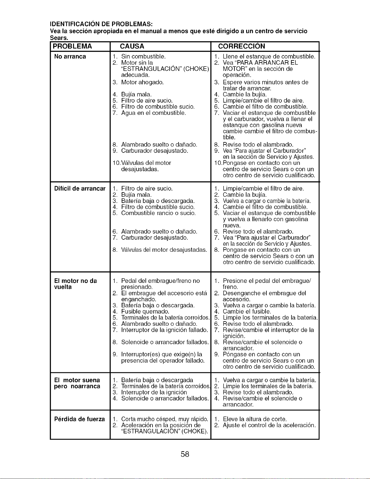
IDENTIFICACION DE PROBLEMAS:
Vea la seccion apropiada en el manual a menos que este dirigido a un centro de servicio
Sears.
PROBLEMA
No arranca
Dificil de arrancar
El motor no da
vuelta
El motor suena
pero noarranca
Perdida de fuerza
CAUSA
1. Sin combustible. 1.
2. Motor sin la 2.
"ESTRANGULACION" (CHOKE)
adecuada.
3. Motor ahogado. 3.
4. Bujfa mala. 4.
5. Filtro de aire sucio. 5.
6. Filtro de combustible sucio. 6.
7. Agua en el combustible. 7.
8. Alambrado suelto o daSado. 8.
9. Carburador desajustado. 9.
10.V_tlvulas del motor
desajustadas.
1. Filtro de aire sucio. 1.
2. Bujfa mala. 2.
3. Baterfa baja o descargada. 3.
4. Filtro de combustible sucio. 4.
5. Combustible rancio o sucio. 5.
6. Alambrado suelto o daSado. 6.
7. Carburador desajustado. 7.
8. Wlvulas del motor desajustadas. 8.
1. Pedal del embrague/freno no 1.
presionado.
2. El embrague del accesorio est,. 2.
enganchado.
3. Baterfa baja o descargada. 3.
4. Fusible quemado. 4.
5. Terminales de la baterfa corrofdos. 5.
6. Alambrado suelto o daSado. 6.
7. Interruptor de la ignici6n fallado. 7.
8. Solenoide o arrancador fallados. 8.
9. Interruptor(es) que exige(n)la 9.
presencia del operador fallado.
1. Baterfa baja o descargada 1.
2. Terminales de la baterfa corrofdos. 2.
3. Interruptor de la ignici6n 3.
4. Solenoide o arrancador fallados. 4.
1. Corta mucho cesped, muy r_tpido. 1.
2. Aceleraci6n en la p.osici6n de 2.
"ESTRANGULACION" (CHOKE).
CORRECCION
Llene el estanque de combustible.
Vea "PARA ARRANCAR EL
MOTOR" en la secci6n de
operaci6n.
Espere varios minutos antes de
tratar de arrancar.
Cambie la bujfa.
Limpie/cambie el filtro de aire.
Cambie el filtro de combustible.
Vaciar el estanque de combustible
y el carburador, vuelva a Ilenar el
estanque con gasolina nueva
cambie cambie el filtro de combus-
tible.
Revise todo el alambrado.
Vea "Para ajustar el Carburador"
en la seccidn de Servicio y Ajustes.
10.Pongase en contacto con un
centro de servicio Sears o con un
otro centro de servicio cualificado.
Limpie/cambie el filtro de aire.
Cambie la bujfa.
Vuelva a cargar o cambie la bateria.
Cambie el filtro de combustible.
Vaciar el estanque de combustible
y vuelva a Ilenarlo con gasolina
nueva.
Revise todo el alambrado.
Vea "Para ajustar el Carburador"
en la secci6n de Servicio y Ajustes.
Pongase en contacto con un
centro de servicio Sears o con un
otro centro de servicio cualificado.
Presione el pedal del embrague/
freno.
Desenganche el embrague del
accesorio.
Vuelva a cargar o cambie la baterfa.
Cambie el fusible.
Limpie los terminales de la baterfa.
Revise todo el alambrado.
Revise/cambie el interruptor de la
ignlclon.
Revise/cambie el solenoide o
arrancador.
P6ngase en contacto con un
centro de servicio Sears o con un
otro centro de servicio cualificado.
Vuelva a cargar o cambie la baterfa.
Limpie los terminales de la baterfa.
Revise todo el alambrado.
Revise/cambie el solenoide o
arrancador.
Eleve la altura de corte.
Ajuste el control de la aceleracidn.
58
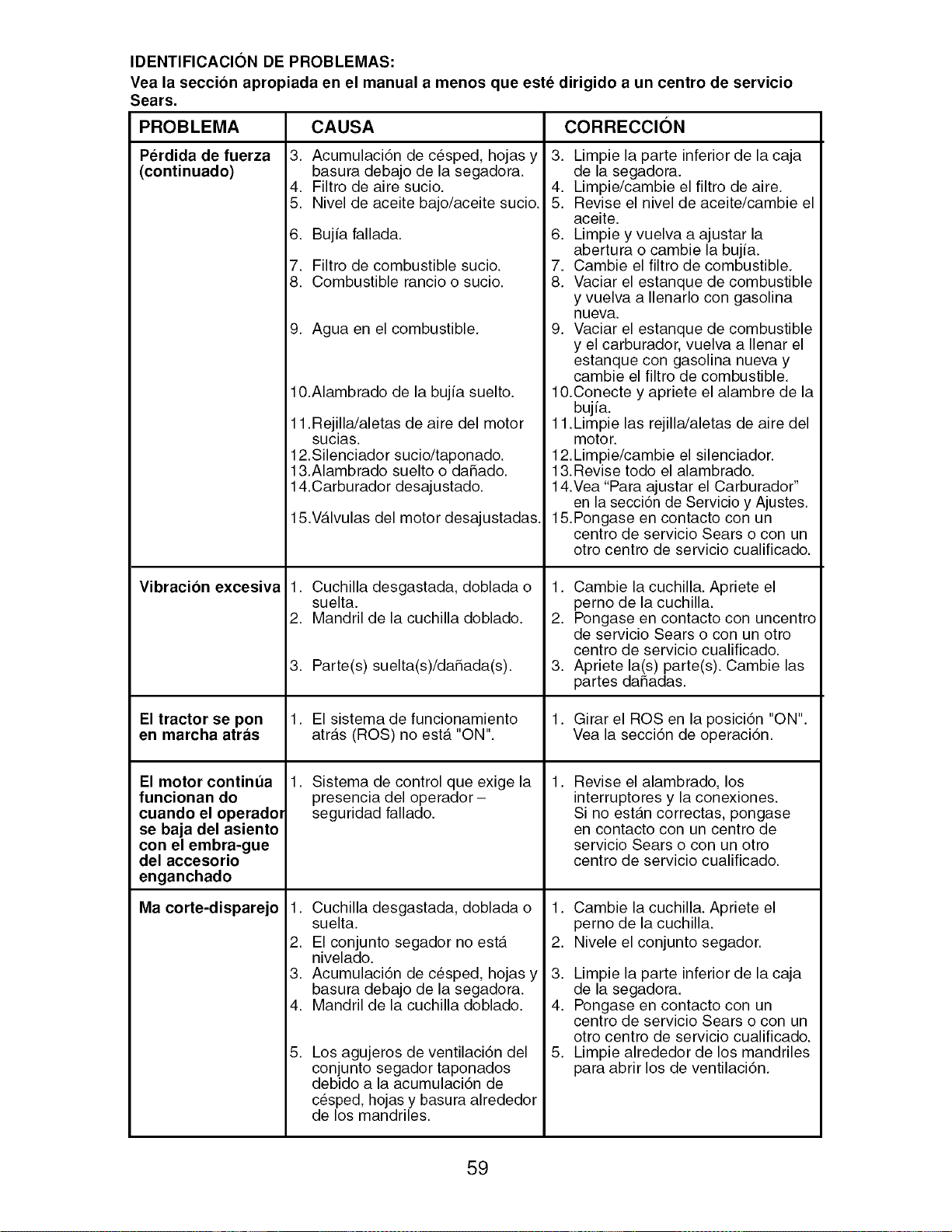
IDENTIFICACION DE PROBLEMAS:
Vea la seccion apropiada en el manual a menos que este dirigido a un centro de servicio
Sears.
CORRECCION
PROBLEMA
Perdida de fuerza
(continuado)
Vibracion excesiva
El tractor se pon
en marcha atras
El motor continua
funcionan do
cuando el operadol
se baja del asiento
con el embra-gue
del accesorio
enganchado
Ma corte-disparejo
CAUSA
3. Acumulaci6n de c_sped, hojas y
basura debajo de la segadora.
4. Filtro de aire sucio.
5. Nivel de aceite bajo/aceite sucio.
6. Bujia fallada.
7. Filtro de combustible sucio.
8. Combustible rancio o sucio.
9. Agua en el combustible.
10.Alambrado de la bujia suelto.
11 .Rejilla/aletas de aire del motor
sucias.
12.Silenciador sucio/taponado.
13.Alambrado suelto o daSado.
14.Carburador desajustado.
15.V_.lvulas del motor desajustadas.
1. Cuchilla desgastada, doblada o
suelta.
2. Mandril de la cuchilla doblado.
3. Parte(s) suelta(s)/daSada(s).
1. El sistema de funcionamiento
atr_.s (ROS) no est,. "ON".
1. Sistema de control que exige la
presencia del operador-
seguridad fallado.
1. Cuchilla desgastada, doblada o
suelta.
2. El conjunto segador no est,.
nivelado.
3. Acumulaci6n de cesped, hojas y
basura debajo de la segadora.
4. Mandril de la cuchilla doblado.
,
Los agujeros de ventilaci6n del
con junto segador taponados
debido a la acumulaci6n de
cesped, hojas y basura alrededor
de los mandriles.
3. Limpie la parte inferior de la caja
de la segadora.
4. Limpie/cambie el filtro de aire.
5. Revise el nivel de aceite/cambie el
aceite.
6. Limpie y vuelva a ajustar la
abertura o cambie la bujia.
7. Cambie el filtro de combustible.
8. Vaciar el estanque de combustible
y vuelva a Ilenarlo con gasolina
nueva.
9. Vaciar el estanque de combustible
y el carburador, vuelva a Ilenar el
estanque con gasolina nueva y
cambie el filtro de combustible.
10.Conecte y apriete el alambre de la
bujia.
11.Limpie las rejilla/aletas de aire del
motor.
12.Limpie/cambie el silenciador.
13.Revise todo el alambrado.
14.Vea "Para ajustar el Carburador"
en la secci6n de Servicio y Ajustes.
15.Pongase en contacto con un
centro de servicio Sears o con un
otro centro de servicio cualificado.
1. Cambie la cuchilla. Apriete el
perno de la cuchilla.
2. Pongase en contacto con uncentro
de servicio Sears o con un otro
centro de servicio cualificado.
3. Apriete la(s) parte(s). Cambie las
partes da_adas.
1. Girar el ROSen la posici6n "ON".
Vea la secci6n de operaci6n.
,
Revise el alambrado, los
interruptores y la conexiones.
Si no est_.n correctas, pongase
en contacto con un centro de
servicio Sears o con un otro
centro de servicio cualificado.
,
2.
3.
4.
,
Cambie la cuchilla. Apriete el
perno de la cuchilla.
Nivele el conjunto segador.
Limpie la parte inferior de la caja
de la segadora.
Pongase en contacto con un
centro de servicio Sears o con un
otro centro de servicio cualificado.
Limpie alrededor de los mandriles
para abrir los de ventilaci6n.
59
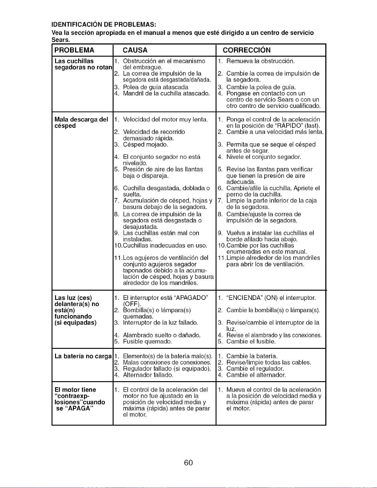
IDENTIFICACION DE PROBLEMAS:
Vea la seccion apropiada en el manual a menos que este dirigido a un centro de servicio
Sears.
PROBLEMA
Las cuchillas
segadoras no rotan
Mala descarga del
cesped
Las luz (ces)
delantera(s) no
esta(n)
funcionando
(si equipadas)
La bateria no carga
El motor tiene
"contraexp-
Iosiones"cuando
se "APAGA"
CAUSA
1. Obstrucci6n en el mecanismo
del embrague.
2. La correa de impulsi6n de la
segadora esta desgastada/daSada.
3. Polea de guia atascada
4. Mandril de la cuchilla atascado.
1. Velocidad del motor muy lenta.
2. Velocidad de recorrido
demasiado r_.pida.
3. Cesped mojado.
4. El conjunto segador no est,.
nivelado.
5. Presi6n de aire de las Ilantas
baja o dispareja.
6. Cuchilla desgastada, doblada o
suelta.
7. Acumulaci6n de cesped, hojas y
basura debajo de la segadora.
8. La correa de impulsi6n de la
segadora est,. desgastada o
desajustada.
9. Las cuchillas est_.n mal con
instaladas.
10.Cuchillas inadecuadas en uso.
11.Los agujeros de ventilaci6n del
conjunto agujeros segador
taponados debido a la acumu-
laci6n de cesped, hojas y basura
alrededor de los mandriles.
,
2.
3.
4.
5.
El interruptor est,. "APAGADO"
(OFF).
Bombilla(s) o I_.mpara(s)
quemadas.
Interruptor de la luz fallado.
Alambrado suelto o daSado.
Fusible quemado.
1. Elemento(s) de la bateria male(s).
2. Malas conexiones de conexiones.
3. Regulador fallado (si equipado).
4. Alternador fallado.
, El control de la aceleraci6n del
motor no rue ajustado en la
posici6n de velocidad media y
maxima (r_.pida) antes de parar
el motor.
CORRECCION
1. Remueva la obstrucci6n.
2. Cambie la correa de impulsi6n de
la segadora.
3. Cambie la polea de guia.
4. Pongase en contacto con un
centro de servicio Sears o con un
otro centro de servicio cualificado.
1. Ponga el control de I.aaceleraci6n
en la posici6n de "RAPIDO" (fast).
2. Cambie a una velocidad m_.s lenta.
3. Permita que se seque el cesped
antes de segar.
4. Nivele el conjunto segador.
5. Revise las Ilantas para verificar
que tienen la presi6n de aire
adecuada.
6. Cambie/afile la cuchilla. Apriete el
perno de la cuchilla.
7. Limpie la parte inferior de la caja
de la segadora.
8. Cambie/ajuste la correa de
impulsi6n de la segadora.
9. Vuelva a instalar las cuchillas el
borde afilado hacia abajo.
10.Cambie por las cuchillas
enumeradas en este manual.
11.Limpie alrededor de los mandriles
para abrir los de ventilaci6n.
1. "ENCIENDA" (ON) el interruptor.
2. Cambie la bombilla(s) o I_tmpara(s).
3. Revise/cambie el interruptor de la
luz.
4. Revise el alarnbrado y las conexiones.
5. Cambie el fusible.
1. Cambie la bateria.
2. Revise/limpie todas las cables.
3. Cambie el regulador.
4. Cambie el alternador.
, Mueva el control de la aceleraci6n
a la posici6n de velocidad media y
m_txima (r_.pida) antes de parar
el motor.
60

61

62
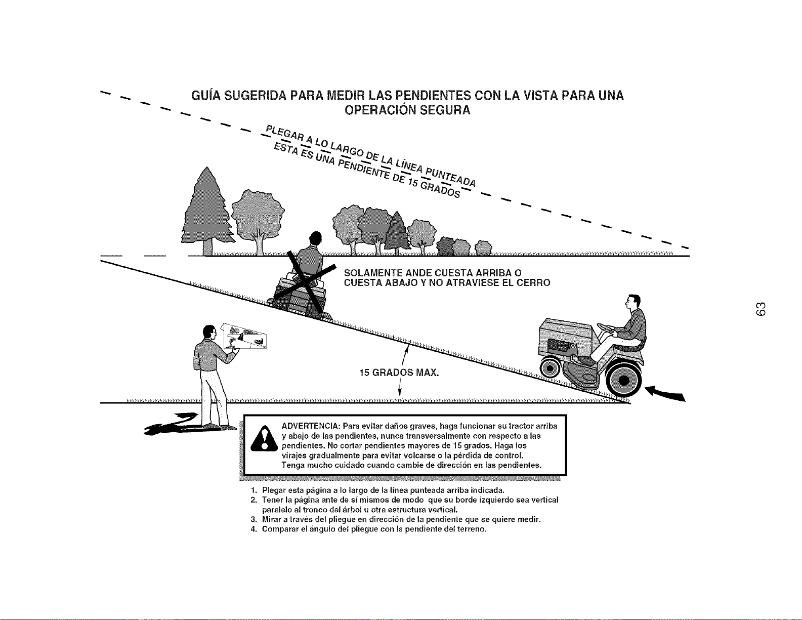
,-.,...
GUiA SUGERIDA PARA MEDIR LAS PENDIENTES CON LA VISTA PARA UNA
OPERACION SEGURA
SOLAMENTE ANDE CUESTA ARRIBA O
CUESTA ABAJO Y NO ATRAVIESE EL CERRO
O3
(.C)
15 GRADOS MAX.
!
_ DVERTENCIA: Para evitar dahos graves, haga funcionar su tractor arriba
y abajo de las pendientes, nunca transversalmente con respecto alas
pendientes. No cortar pendientes mayores de 15 grados. Haga los
virajes gradualmente para evitar volcarse o la perdida de control
Tenga mucho cuidado cuando cambie de direcci6n en las pendientes.
1. Plegar esta p_gina a ]o largo de la linea punteada arriba indicada.
2. Tenet la pagina ante de si mismos de modo que su horde izquierdo sea vertical
paralelo al tronco del arbol u otra estructura vertical
3. Mirar a trav_s del pliegue en direcci6n de la pendiente que se quiere medir.
4. Comparar el _ngulo del pliegue con la pendiente del terreno.

Your Home
For repair - in your home - of all major brand appliances,
lawn and garden equipment, or heating and cooling systems,
no matter who made it, no matter who sold it!
For the replacement parts, accessories and
owner's manuals that you need to do-it-yourself.
For Sears professional installation of home appliances
and items like garage door openers and water heaters.
1-800-4-MY-HOME ® Anytime, day or night
(1-800-469-4663) (U.S.A. and Canada)
www.sears.com www.sears,ca
Our Home
For repair of carry-in products like vacuums, lawn equipment,
and electronics, call or go on-line for the nearest
Sears Parts and Repair Center.
1-800-488-1222 Anytime, day or night (U.S.A. only)
www.sealrs.com
To purchase a protection agreement (U.S.A.)
or maintenance agreement (Canada) on a product serviced by Sears:
1-800-827-6655 (U,S,A.) 1-800-361-6665 (Canada)
Para pedir servicio de reparaci6n
a domicilio, y para ordenar piezas:
1-888-SU-HOGAR ®
(1-888-784-6427)
Au Canada pour service en frangais:
1-800-LE-FOYER Mc
(1-800-533-6937)
www.sears.ca
Serifs
© Sears Brands,LLC
® Registered Trademark / TMTrademark / SMService Mark of Sears Brands, LLC
® Marca Registrada / TMMarca de Fabrica / SMMarca de Servicio de Sears Brands, LLC
MCMarque de commerce / MDMarque d6posee de Sears Brands, LLC
403346 Rev.1 05.25.06 VB Printed in U.S.A,


