Loading ...
Loading ...
Loading ...
Operator's Manual
Compact Tiller and Cultivator
Check for parts online at www.brutepower.com or call 800-743-4115 M-F 8-5 CST
15
Fill Engine Crankcase
1. Add oil according to engine manual. DO NOT OVERFILL.
Use a clean, high quality detergent oil. Use no special
additives with recommended oils. DO NOT MIX OIL
WITH GASOLINE. Oil level must be full. Check the oil
level by removing oil ll plug. Oil level should be up to
the bottom of the ll plug opening.
2. Always check oil level before starting engine. Refer to
engine manual for capacity and type of oil to use.
Fill Fuel Tank
1. Add gasoline according to engine manual. DO NOT
OVERFILL. Use 87+ octane unleaded ethanol-free
gasoline. If an ethanol blend must be used, use ethanol
fuel stabilizer. DO NOT MIX OIL WITH GASOLINE.
2. Always check gasoline level before starting engine. Refer
to engine manual for capacity and type of gasoline to
use.
7. Rotate lower handlebar assembly away from engine to
provide adequate clearance to install side tine shields
Slide left and right side shields onto center tine shield.
Align side shield grooves with center tine shield and push
until an audible click is heard and/or felt. This indicates
that the tine shield has engaged with the shield lock
and is secured all the way on. Rotate lower handlebar
assembly up towards engine and insert hand knob bolts
through upper mount holes and tighten. Hand knob
bolts can be inserted into one of two sets of holes depending
on desired handlebar height.
8. Remove four M5 x 12 mm Hex Flange Bolts from pulley
box cover. Place pulley box cover onto pulley box and
secure with the four M5 x 12 mm Hex Flange Bolts using
an 8mm wrench.
9. Slide drag stake through drag stake mount and secure
with lockpin at the desired depth.
10. Align right handlebar mount holes with lower handlebar
assembly mount holes at one of two height positions.
Secure right handlebar with two M8 x 40 mm Hex Flange
Bolts, two M8 x 25 mm Flat Washers, and Two M8 Nylock
Nuts and hand tighten. Repeat for left handlebar. Align
middle handlebar with mount holes of right and left
handlebars. Secure middle handlebar with two M8 x 40
mm Hex Bolts, two M8 x 16 mm Flat Washers, and two
M8 Nylock Nuts. Tighten all handlebar hardware with a
combination of 10mm and 13mm wrenches. Use two zip
ties to secure the forward cable. (optional).
NOTICE
ENGINE IS SHIPPED FROM FACTORY WITHOUT
OIL. YOU MUST ADD ENGINE OIL BEFORE
STARTING ENGINE.
OPERATION
CONTROLS
Drive Safety Control Lever
Pulling down on drive safety control lever engages the tines.
Releasing the drive safety control lever to a neutral position
disengages the tines.
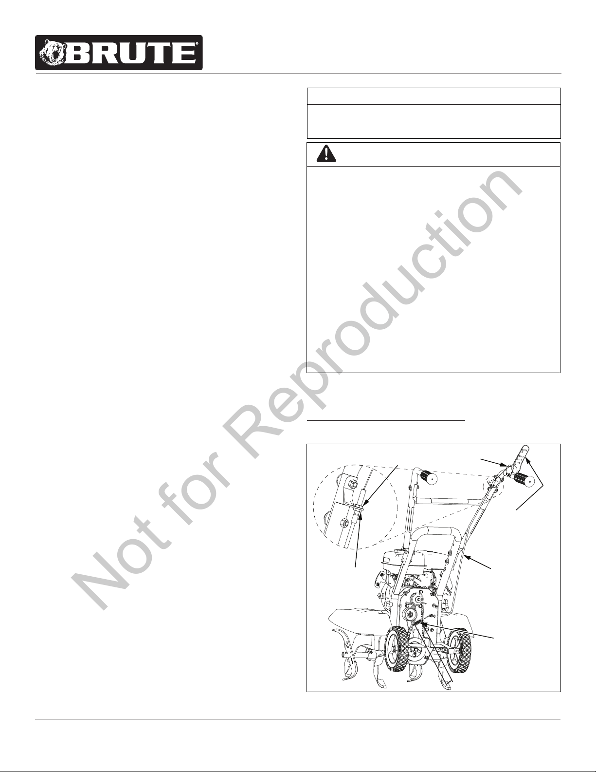
Belt Tension Adjustment
Proper belt tension is critical to good performance. After 1/2
hour of operation, all cables may have to be adjusted due to
initial stretch. Thereafter, check tension after every 10 hours of
operation. Proper tension is achieved when the beehive spring
extends 1/8” - 1/4” when drive lever is engaged.
To increase belt tension do as follows:
1. Loosen upper jam nut. SEE FIGURE 5
BEEHIVE
SPRING
DRIVE SAFETY
CONTROL LEVER
DISENGAGED
UPPER
JAM NUT
LOWER
JAM NUT
FORWARD
CABLE
Z-BEND
LINKAGE
1/8” - 1/4” STRETCH
WARNING
THIS INFORMATION IS PROVIDED HERE ONLY
TO INTRODUCE THE CONTROLS. DO NOT START
THE ENGINE AT THIS TIME. PLEASE READ THIS
SECTION AND ALL OPERATING AND SAFETY
INSTRUCTIONS BEFORE STARTING YOUR TILLER.
• AS A SAFETY PRECAUTION, THE DRIVE
SAFETY CONTROL LEVER WILL NOT LOCK IN
THE FORWARD POSITION.
• TO STOP THE TINES AT ANY TIME, RELEASE
THE DRIVE SAFETY CONTROL LEVER.
• PROTECTIVE FOOTWEAR MUST BE WORN
WHILE OPERATING THIS PRODUCT.
• ENGINE SHOULD BE OFF BEFORE ADJUSTING
ANY CONTROLS.
• DO NOT ADJUST TILLING DEPTH UNLESS
DRIVE SAFETY CONTROL LEVER IS RELEASED
TO THE NEUTRAL POSITION.
FIGURE 5
Not for Reproduction
Loading ...
Loading ...
Loading ...