Loading ...
Loading ...
Loading ...
Operator's Manual
Compact Tiller and Cultivator
Check for parts online at www.brutepower.com or call 800-743-4115 M-F 8-5 CST
14
UNPACKING AND ASSEMBLY CONTINUED
Carton Contents
• Tiller Assembly
• Hardware Parts Bag:
A - 4X - M8 x 40 mm Hex Bolt
B - 4X - M8 x 40 mm Hex Flange Bolt
C - 2X - M8 x 45 mm Hex Bolt
E - 6X - M8 x 25 mm Flat Washer
F - 2X - M8 x 15 mm Spring Lock Washer
G - 2X - M8 x 16 mm Flat Washer
H - 10X - M8 Nylock Nut
I - 1X - Lock Pin
J - 2X - Tine Shaft Sleeve
• Manual Parts Bag
• Left, Right, and Middle Handlebars
• Left and Right Side Shields
• Left and Right Tine Sets
• Pulley Box Cover
D - 4X - M5 x 25 mm Hex Flange Bolt
• Drag Stake
• Foam Protection, Corner Supports and Packaging
Materials
ASSEMBLY STEPS
1. Open top of carton and remove top foam piece
containing middle handlebar, and hardware parts bag, as
well as the four corner supports. Carefully cut the four
corners of the carton with a box cutter. Do not attempt
to lift tiller assembly out of box.
2. Carefully remove tiller assembly, tine sets, side shields,
pulley box cover, and remaining packaging materials
from lower foam.
3. Remove hand knob bolts from both sides of tiller.
Separate lower handlebar assembly from pulley box and
cut zip ties to remove handlebars.
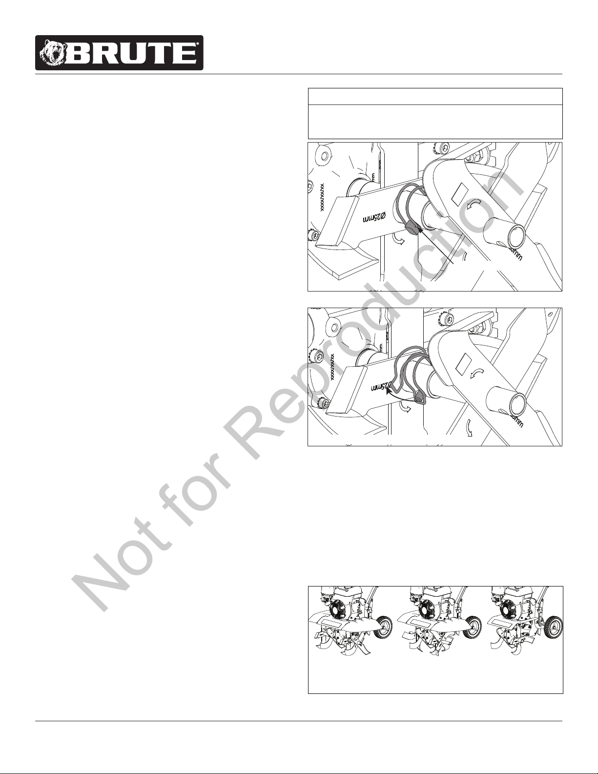
4. Remove lock pin from one tine set. Slide outer tine and
rotate to align with the second hole position of inner tine,
then secure with lock pin. Repeat for other tine set.
NOTE: Ensure the lock pins and tines are correctly
installed. Lock pins must be installed so that the pin
enters the hole in the tine from the front of the tiller,
and so the wire bale hinges over the top of the tine pipe
and latches to the protruding pin on the back side of
the tine. Tines can inadvertently detach during tilling if
lock pins are not installed correctly! SEE FIGURES 23
5. Check that arrows are pointing in the direction of forward
rotation and slide left tine set over tine shaft sleeve,
align mounting holes with the left tine shaft, and secure
with the M8 x 45 mm Hex Bolt, M8 x 15 mm Spring Lock
Washer, and M8 Nylock Nut. Tighten with two 13mm
wrenches. Repeat for right tine set on right tine shaft.
Tines can be congured for multiple tilling situations.
SEE FIGURE 4
a. Wide Tilling - Install according to Assembly Step 5
b. Narrow Tilling - Remove outer tines and lock pins and
install on opposite tine shaft with the directional arrows
pointing in the direction of forward rotation.
c. Narrow Cultivating - Remove outer tines and lock pins.
6. Align lower handlebar assembly mount holes with lower
mount holes on pulley box. Place one M8 x 25 mm Flat
Washer on one M8 x 40 mm Hex Bolt and insert through
lower mount hole of lower handlebar assembly and
pulley box. Place one M8 Nylock Nut on bolt and tighten
with two 13mm wrenches. Repeat for other side.
FIGURE 2
FIGURE 3
LOCK PIN INSTALLED CORRECTLY
LOCKPIN INSTALLED INCORRECTLY
LOCK PIN HINGE
WIDE
TILLING
21 INCHES
NARROW
TILLING
16 INCHES
NARROW
CULTIVATING
11 INCHES
FIGURE 4
NOTICE
HANDLE ROTOTILLER WITH CARE. DO NOT
DAMAGE FORWARD CABLE WHEN TRANSPORTING
OR OPERATING.
Not for Reproduction
Loading ...
Loading ...
Loading ...