Loading ...
Loading ...
Loading ...
15
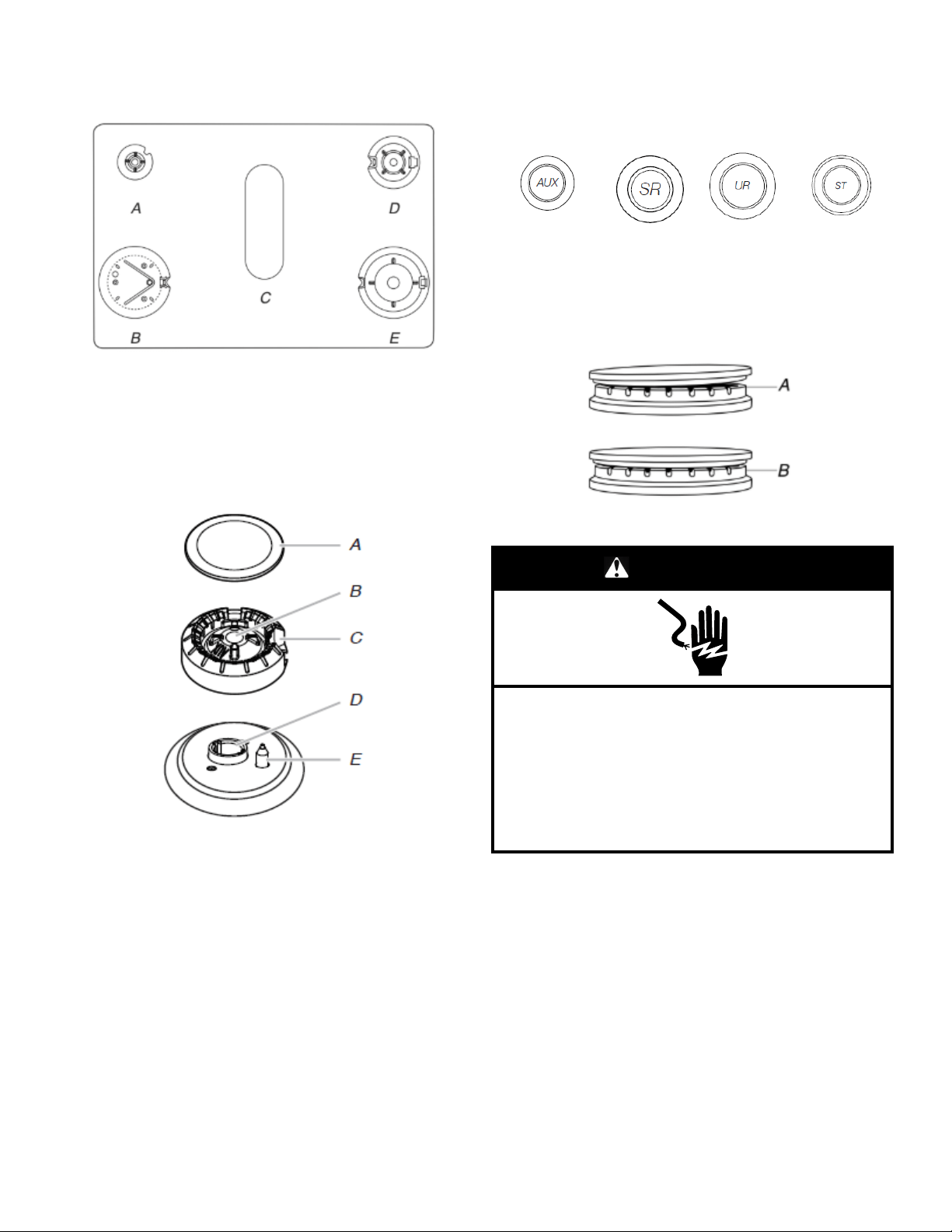
4. Remove cooktop burner caps and bases from package
containing parts. Place the burner bases as indicated by the
following illustration.
A. Small (Auxiliary)
B. X-Large (Stack)
C. Oval (OV)
D. Medium (Semi Rapid)
E. Large (Ultra Rapid)
NOTE: Each round burner base is marked with one of the
following: AUX, SR, UR, ST.
5. Align the gas tube opening in the burner base with the orifice
holder on the cooktop and the igniter electrode with the notch
in the burner base.
A. Burner cap
B. Gas tube opening
C. Burner base
D. Orifice holder
E. Igniter electrode
6. Place the burner caps on the appropriate burner bases.
IMPORTANT: The bottom of the small and medium caps are
different. Do not put the wrong size burner cap on the burner
base. Each round burner cap is marked with an AUX, SR, UR,
or ST to match with a letter on the burner base.
Small cap
(Auxiliary)
Medium cap
(Semi Rapid)
Large cap
(Ultra Rapid)
X-Large cap
(Stack)
Burner caps should be level when properly positioned. If
burner caps are not properly positioned, surface burners will
not light. The burner cap should not rock or wobble when
properly aligned.
A. Incorrect
B. Correct
WARNING
Electrical Shock Hazard
Plug into a grounded 3 prong outlet.
Do not remove ground prong.
Do not use an adapter.
Do not use an extension cord.
Failure to follow these instructions can result in death,
fire, or electrical shock.
7. Plug into a grounded 3-prong outlet.
Verify Anti-Tip Bracket Is Installed
and Engaged
On Ranges Equipped with a Storage Drawer:
1. Slide range into final location, making sure rear leveling leg
slides into anti-tip bracket.
2. Remove the storage drawer. See the “Remove/ Replace
Drawer” section.
3. Use a flashlight to look underneath the bottom of the range.
4. Visually check that the rear range foot is inserted into the slot
of the anti-tip bracket.
Loading ...
Loading ...
Loading ...