
OWNER MANUAL
MANUALE D’USO
BEDIENUNGSANLEITUNG
MQ100L
MQ100L-W
- WALL-MOUNTED COLUMN
LOUDSPEAKER
- COLONNA SONORA PER
INSTALLAZIONE A PARETE
- TONSÄULE ZUR WANDMONTAGE


3
ENGLISH
IMPORTANT NOTES
Before connecting and using this product, please read this instruction manual carefully and
keep it on hand for future reference. This manual is to be considered an integral part of
this product and must accompany it when it changes ownership as a reference for correct
installation and use as well as for the safety precautions.
RCF S.p.A. will not assume any responsibility for the incorrect installation and / or use of this
product.
WARNING: To prevent the risk of re or electric shock, never expose this loudspeaker to rain
or humidity and also protect it from dust.
SAFETY AND OPERATING PRECAUTIONS
1. All the precautions, in particular the safety ones, must be read with special attention, as
they provide important information.
2. Loudspeaker lines (amplier outputs) can have a sufciently high voltage (i.e. 100-70 V) to
involve a risk of electrocution: never install or connect this loudspeaker when the line is alive.
3. Make sure all connections have been made correctly and the loudspeaker input voltage (in
a constant voltage system) or its impedance is suitable for the amplier output.
4. Protect loudspeaker lines from damage; make sure they are positioned in a way that they
cannot be stepped on or crushed by objects.
5. Make sure that no objects or liquids can get into this product, as this may cause a short
circuit.
6. Never attempt to carry out any operations, modications or repairs that are not expressly
described in this manual.
Contact your authorized service centre or qualied personnel should any of the following
occur:
The loudspeaker does not function (or works in an anomalous way).
The cable has been damaged.
Objects or liquids have got into the unit.
The loudspeaker has been damaged due to heavy impacts or re.
7. Should the loudspeaker emit any strange odours or smoke, remove it from the line after
having immediately switched the amplier off.
8. Do not connect this product to any equipment or accessories not foreseen.
For suspended installation, only use the dedicated anchoring points and do not try to hang
this loudspeaker by using elements that are unsuitable or not specic for this purpose.
Also check the suitability of the support surface to which the product is anchored (wall,
ceiling, structure, etc.), and the components used for attachment (screw anchors, screws,
brackets not supplied by RCF etc.), which must guarantee the security of the system /
installation over time, also considering, for example, the mechanical vibrations normally
generated by transducers.
9. RCF S.p.A. strongly recommends this product is only installed by professional qualied
installers (or specialised rms) who can ensure a correct installation and certify it according to
the regulations in force.
The entire audio system must comply with the current standards and regulations regarding
electrical systems.
10. There are numerous mechanical and electrical factors to be considered when installing
a professional audio system (in addition to those which are strictly acoustic, such as sound
pressure, angles of coverage, frequency response, etc.).
IMPORTANT NOTES
WARNING
SAFETY AND OPERATING PRECAUTIONS

4
ENGLISH
11. Hearing loss
Exposure to high sound levels can cause permanent hearing loss. The acoustic pressure level
that leads to hearing loss is different from person to person and depends on the duration of
exposure.
To prevent potentially dangerous exposure to high levels of acoustic pressure, anyone who is
exposed to these levels should use adequate protection devices.
When a transducer capable of producing high sound levels is being used, it is necessary to
wear ear plugs or protective earphones.
See the technical specications in the instruction manual for the maximum sound pressure the
loudspeaker is capable of producing.
12. To ensure a correct sound reproduction, loudspeaker phase is to be respected
(loudspeakers are connected respecting the amplier polarity). This is important when
loudspeakers are installed adjacent one another, for instance, in the same room.
13. To prevent inductive effects from causing hum, noise and a bad system working,
loudspeaker lines should not be laid together with other electric cables (mains), microphone or
line level signal cables connected to amplier inputs.
14. The loudspeaker cable shall have wires with a suitable section (twisted, if possible, to
reduce inductive effects due to surrounding electro-magnetic elds) and a sufcient electrical
insulation. Refer to local regulations since there may be additional requirements about cable
characteristics.
15. Install this loudspeaker far from any heat source.
16. When connect to its low impedance input, do not overload the loudspeaker with too
much power.
17. Do not use solvents, alcohol, benzene or other volatile substances for cleaning the
external parts of this product.
5
ENGLISH
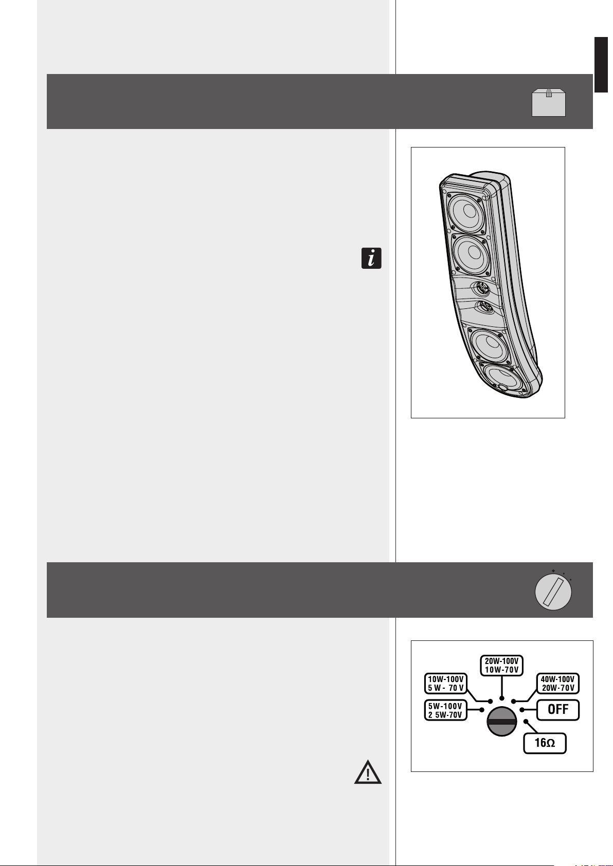
MQ 100L (/ MQ 100L-W) is a 3 way column loudspeaker providing natural hi-delity sound
of both speech (to improve the intelligibility) and music, suitable for sound system having
xed loudspeakers where the environment is acoustically critical or there are architectural
constraints.
The wide horizontal coverage angle (180°) and the 60° vertical dispersion allow the correct
sound reproduction in a wide space, in order to limit feedbacks and improve the sound
directivity (important in halls having a long reverberation time).
The 60° verTical dispersion is asymmeTric: iT is The difference beTween 20° upwards and 40°
downwards. The verTical dispersion axis is in facT already angled 10° downwards, making iT
unnecessary To TilT The sound column excessively.
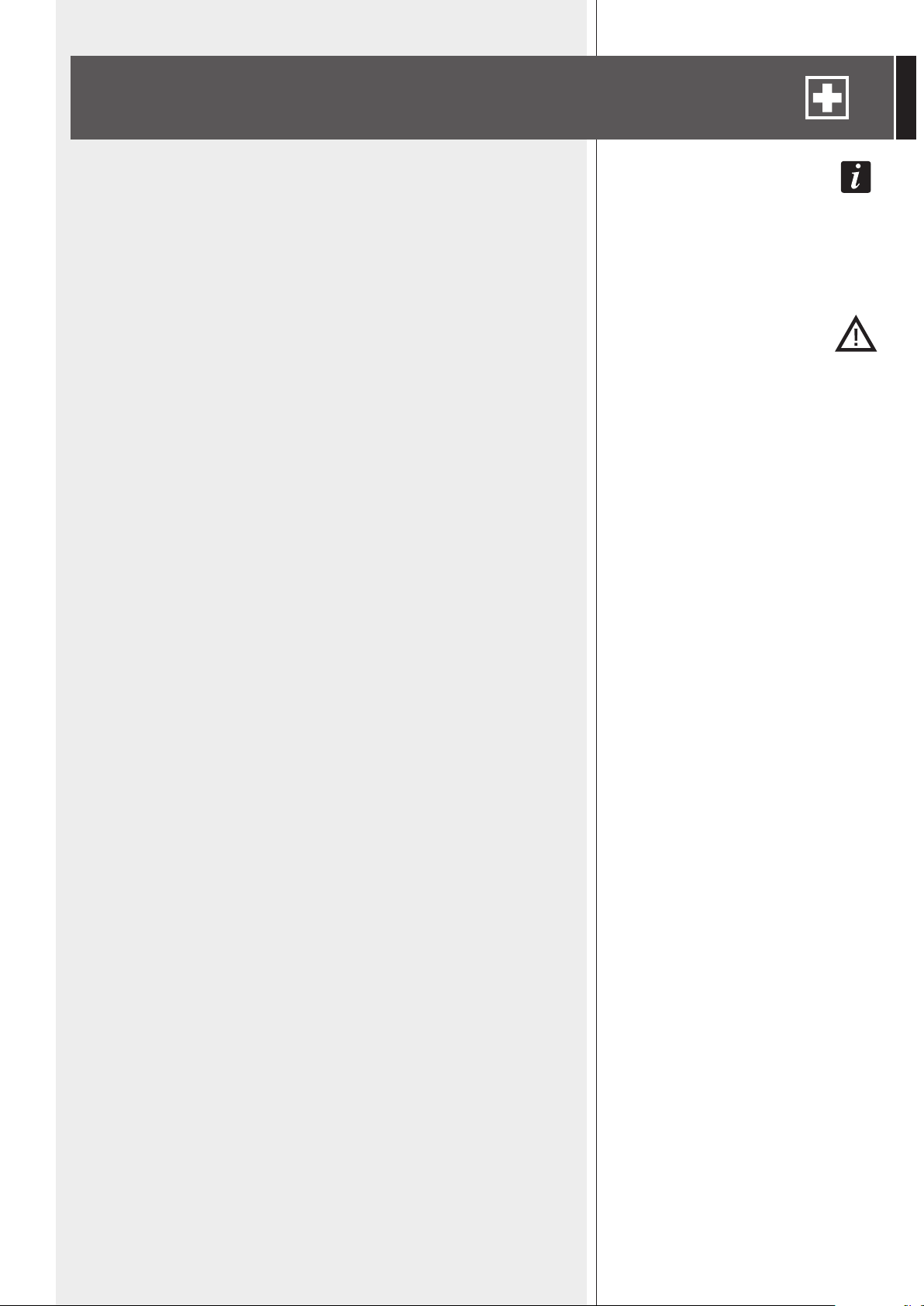
MQ 100L IS EQUIPPED WITH:
- 4 rubber surround 3.5” woofers
- 2 cloth coated 0.75” dome tweeters.
Mounting accessories are included. These
have been studied to keep the column as
close as possible to the wall and simplify
its installation. Its tilt angle can be chosen
among 0° – 5° – 10°.
It includes a transformer inside for the connection to (100 – 70 V) constant voltage lines,
yet it can also be set to 16 Ω (low impedance connection).
The power / mode selection is made by means of the rear panel rotary switch.
LOUDSPEAKER RMS POWER IS:
a. 40 – 20 – 10 – 5 W (selectable), if
connected to a 100 V constant voltage
line.
b. 20 – 10 – 5 – 2.5 W (selectable), if
connected to a 70 V constant voltage
line.
c. Max. 60 W on low impedance (16 Ω).
Its body is made of self-extinguishing (HB level) high density polystyrene.
AVAILABLE IN 2 COLOURS:
- Black MQ 100L
- White MQ 100L –W.
RCF S.P.A. THANKS YOU FOR PURCHASING THIS PRODUCT, WHICH HAS BEEN
DESIGNED TO GUARANTEE RELIABILITY AND HIGH PERFORMANCES.
DESCRIPTION
SETTING (REAR PANEL ROTARY SWITCH)
Use a screwdriver to select.
OFF position: the loudspeaker is disabled (muted).
a. 100 V (/ 70 V) constant voltage line
Select the desired power (referred to a 100
V line) among 5 – 10 – 20 – 40 W.
When using a 70 V line, the power is
halved: 2.5 – 5 – 10 – 20 W.
b. Low impedance input
Set the rotary switch to the 16 Ω position.
WARNING: NEVER sEt thE 16 Ω posItIoN WhEN thE loudspEAkER Is
coNNEctEd to A 100 / 70 V coNstANt VoltAGE lINE.
6
ENGLISH
Loudspeakers are to be installed by qualied personnel, respecting all safety standards.
Loudspeakers are to be installed securely.
Make sure the supporting structure (i.e. wall, plasterboards, wood panels, etc.) has the
necessary mechanical characteristics for the loudspeaker weight, without the risk of a fall
that could damage things or cause an injury.
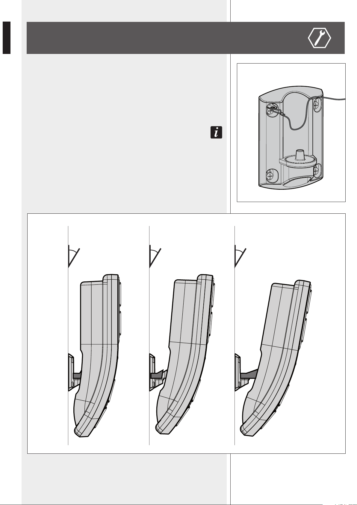
a. Fix (vertically) the support to the wall with four M4 dowels and also an end of
the safety steel wire through the dowel in the top left-hand corner (picture 1).
The connecTing cable (if inside a flush-mounTed pipe) can pass Through The wall-
mounTed supporT boTTom cenTral hole.
b. The mounting bracket is available in 3 different measures to choose the sound
column vertical tilt angle (picture 2a):
- short, no tilt angle (0°)
- medium, tilt angle xed to 5°
- long, tilt angle xed to 10°.
INSTALLATION
PICTURE 1
PICTURE 2a
0° 5° 10°

7
ENGLISH
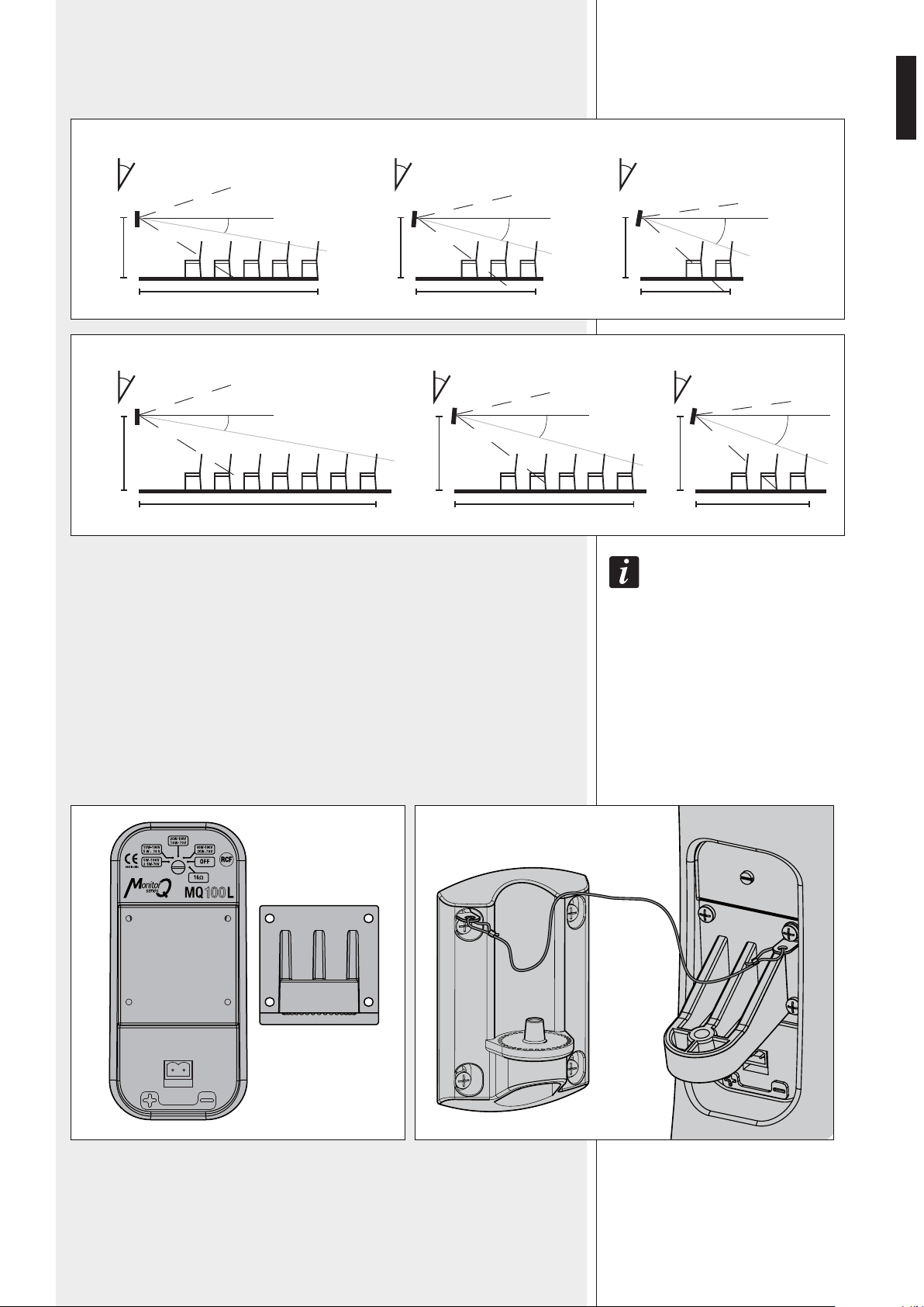
PICTURE 2b
4 m
2 m
5°
15°
6 m
2 m
0°
10°
3 m
2 m
10°
20°
8 m
2.5 m
0°
10°
6 m
2.5 m
5°
15°
4 m
2.5 m
10°
20°
PICTURE 2c
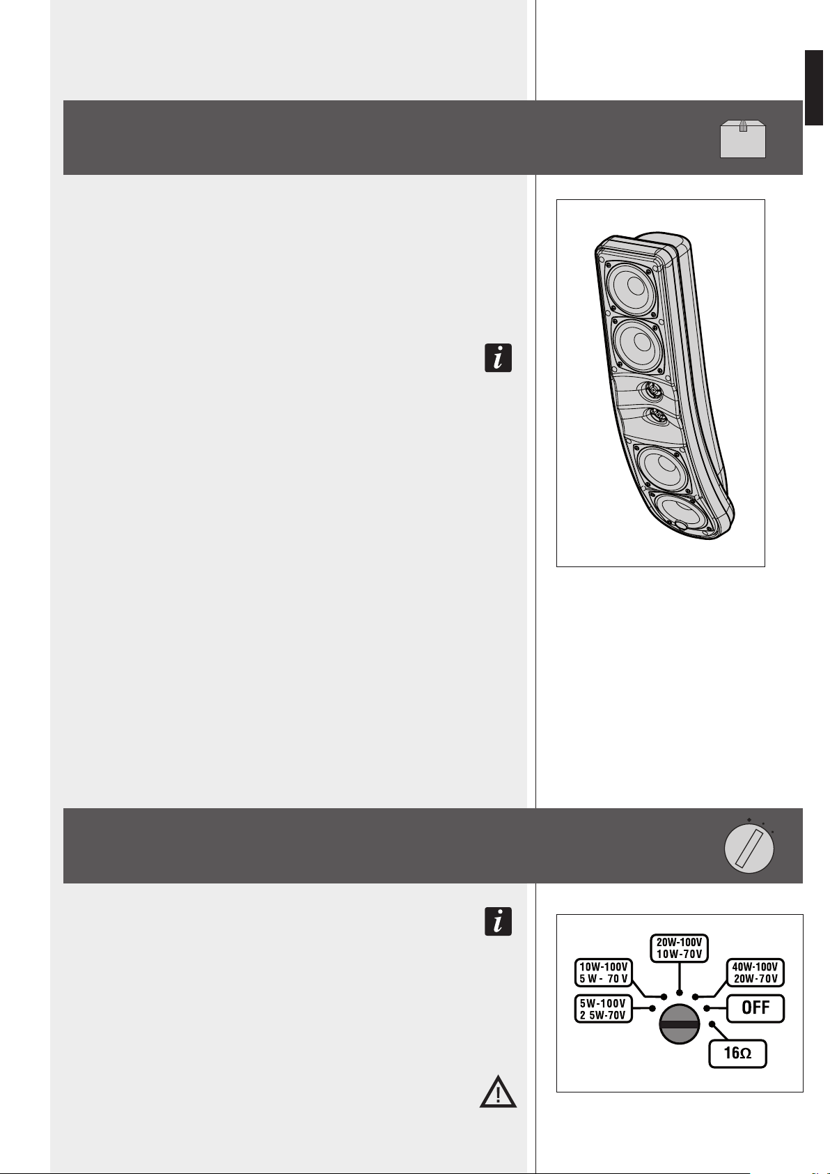
Pictures 2b and 2c: indicative examples of coverage according to the vertical tilt
of the sound column, which its centre is fixed at 2 m / 2.5 m over the floor.
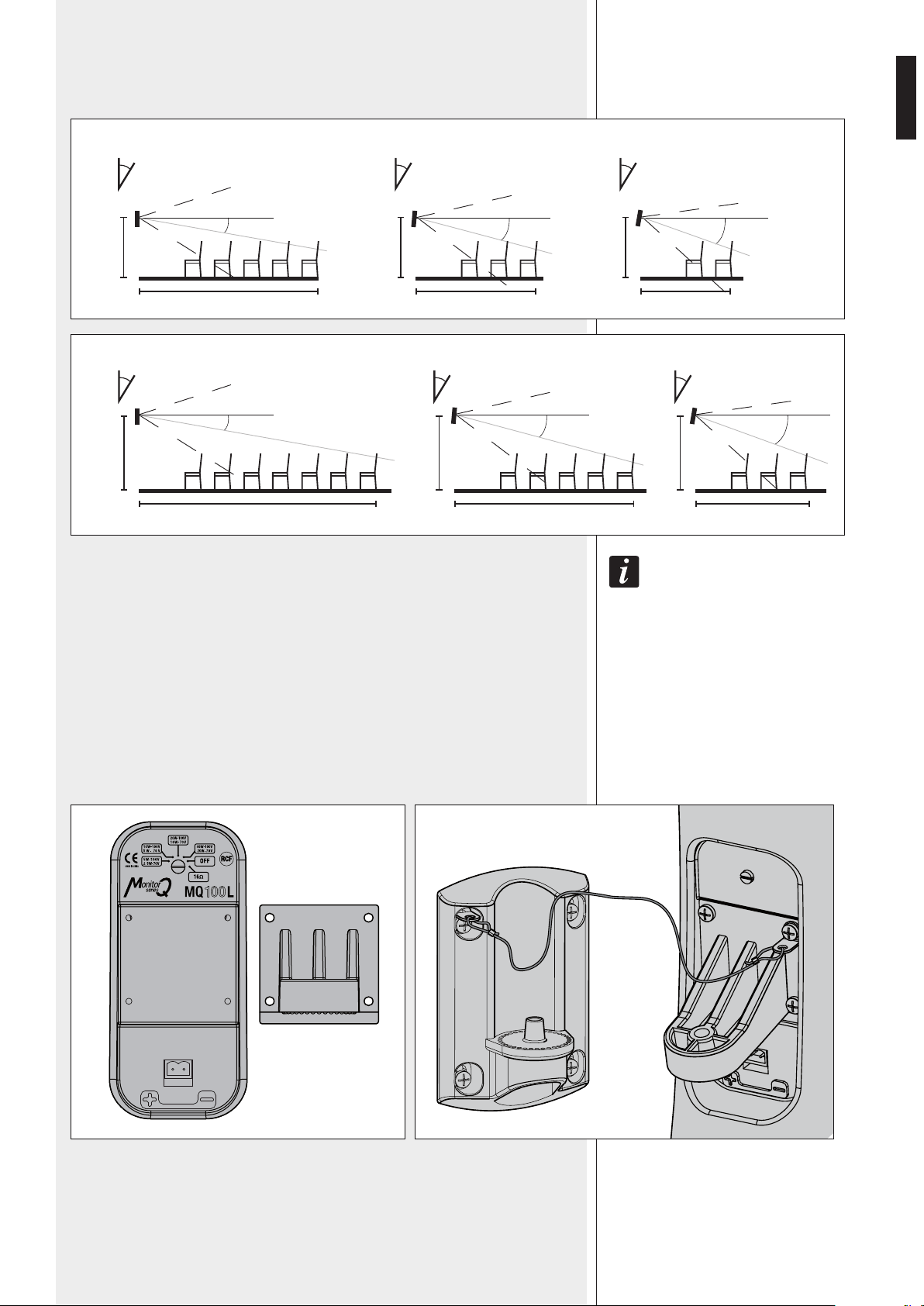
Choose the most suitable mounting bracket and fix it (in the proper way) to the
sound column rear panel (picture 3a) through the 4 self-tapping screws (included).
Fix the other end of the safety steel wire through the self-tapping screw in the top
right-hand corner (picture 3b) of the bracket.
- Without any sound column tilt (0°), the vertical dispersion axis angle is 10°
doWnWards.
- if the sound column tilt angle is 5°, the vertical dispersion axis angle is 15°
doWnWards.
- if the sound column tilt angle is 10°, the vertical dispersion axis angle is 20°
doWnWards.
PICTURE 3bPICTURE 3a
8
ENGLISH
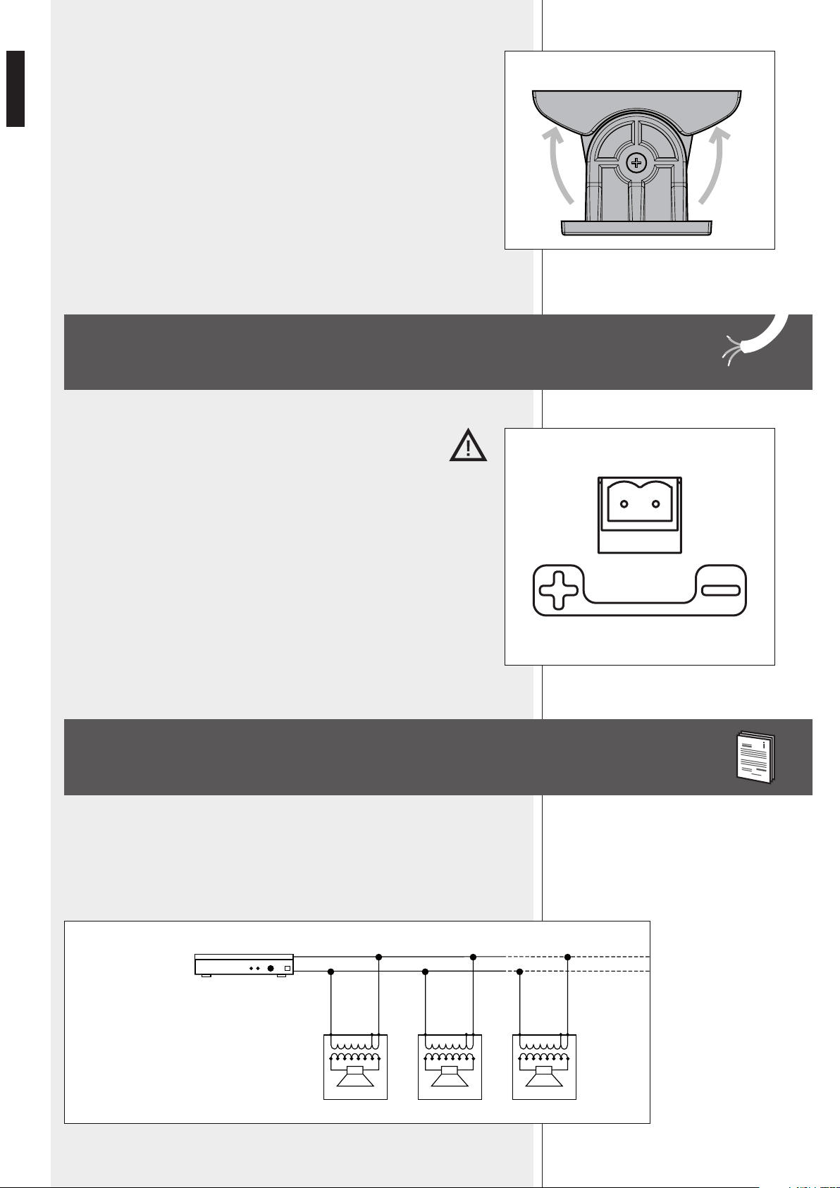
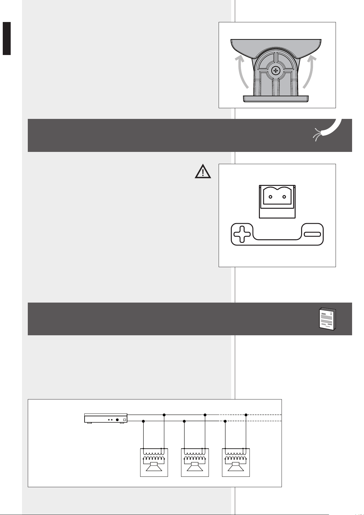
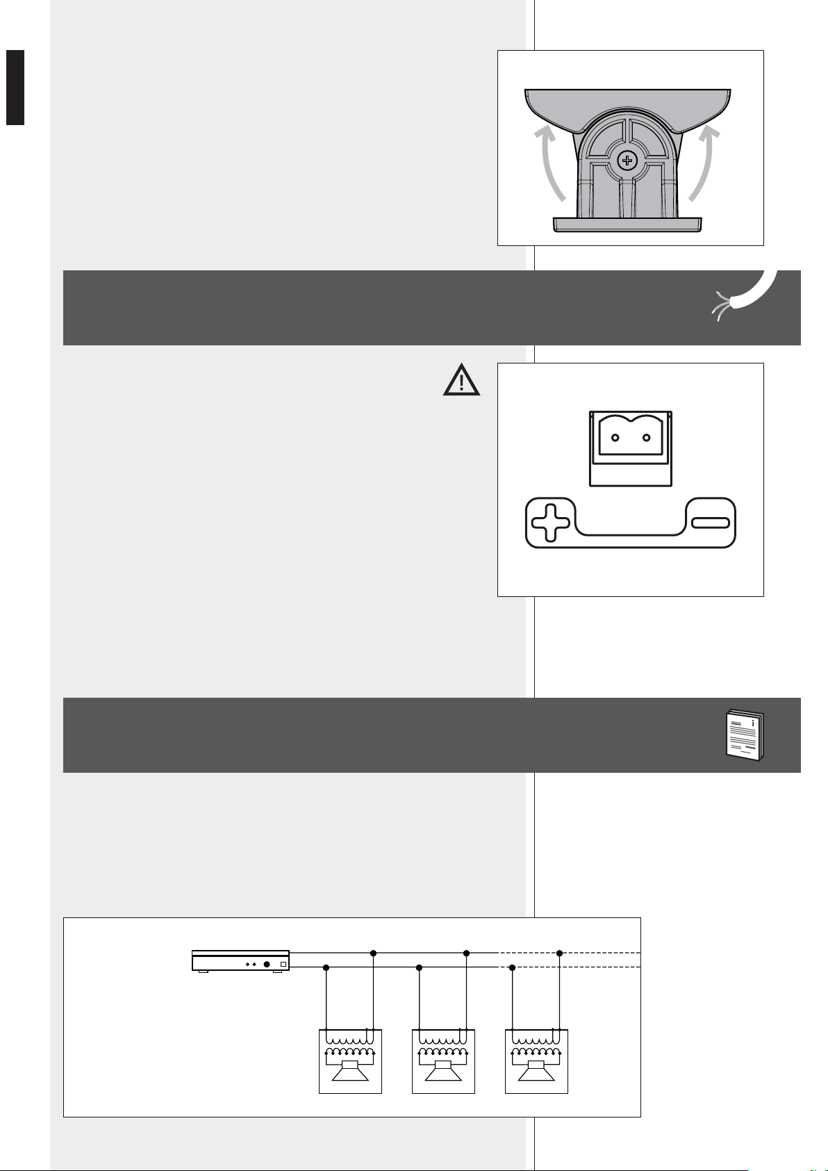
c. Put the sound column on the wall-mount support (through the bracket),
aim it (horizontally) and fix it by tightening the central screw (picture 4).
PICTURE 4
PICTURE 5
CONNECTION
WARNING: loudspeaker connections should be only made by qualied
and experienced personnel having the technical know-how or sufcient
specic instructions (to ensure that connections are made correctly) in
order to prevent any electrical danger.
To prevent any risk of electric shock, do not connect loudspeakers when the
amplier is switched on. Before turning the system on, check all connections and
make sure there are no accidental short circuits. The entire sound system shall be
designed and installed in compliance with the current local laws and regulations
regarding electrical systems.
The input connector is on the column rear panel (picture 5).
Connect the line positive wire (coming from the amplier output usually marked
‘100 V’, ‘70 V’ ‘+’ or ‘a’) to the ‘+’ loudspeaker terminal.
Connect the line negative wire (coming from the amplier output usually marked
‘0’, ‘–’, ‘COM’ or ‘b’) to the ‘–’ loudspeaker terminal.
- The loudspeaker input voltage (Vd) shall correspond to the amplier output voltage (Va).
- The sum of nominal power values (Pd x n) of all loudspeakers connected to the line shall
not exceed the amplier power (Pa).
- Make sure all loudspeakers are connected in phase to ensure a correct sound reproduction.
NOTES ABOUT CONSTANT VOLTAGE SYSTEMS
Pa = Amplier power
Pd = Speaker power
n = Number of speakers
Vd = Speaker input voltage
Va = Amplier output voltage
Amplier
Pa > Pd x n
Vd = Va
+
–
-
+
-
+
Vd = Va
-
+
Vd = Va
Va
9
ENGLISH
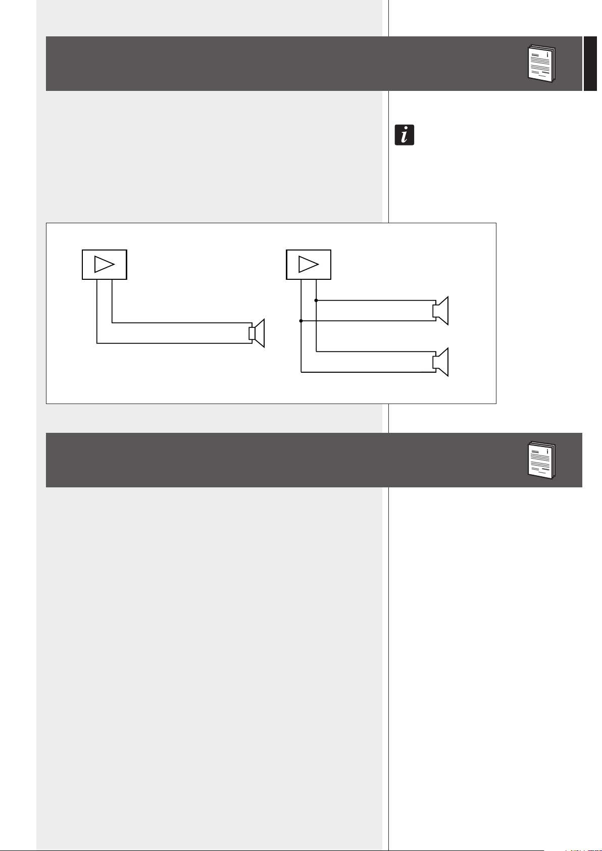
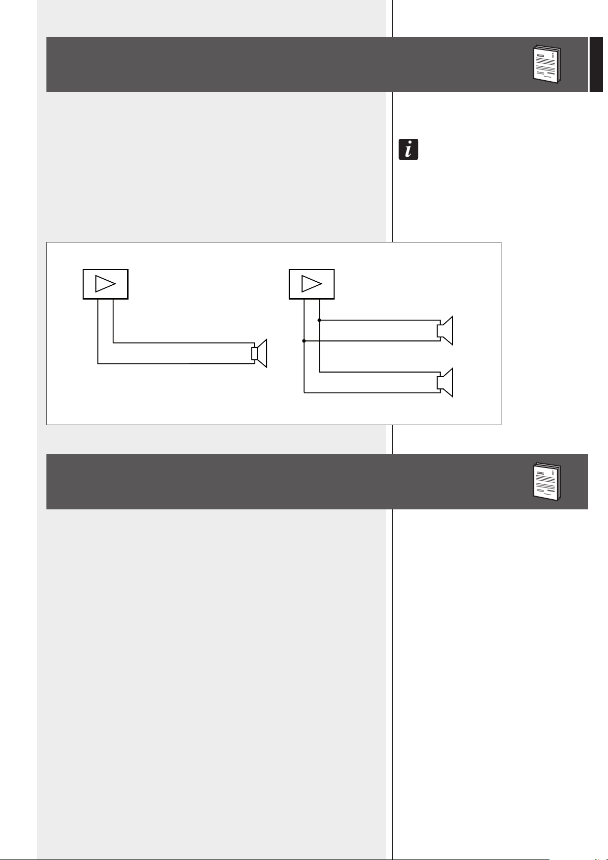
NOTES ABOUT LOW IMPEDANCE CONNECTIONS
ADDITIONAL NOTES
- The total loudspeaker impedance must not be lower than the amplier output impedance.
noTe: a loudspeaker ToTal impedance equal To The amplifier ouTpuT one permiTs To geT The maximum
deliverable power (buT an higher loudspeaker impedance enTails less power).
- The total loudspeaker power shall be adequate for the maximum deliverable power of
the amplier.
- The loudspeaker line shall be as short as possible (for long distances, it may be necessary
to use cables with large cross-section wires).
- Always use cables having wires with an adequate cross-section, considering the cable
length and the total loudspeaker power.
- Loudspeaker lines must be kept separated from mains cable, microphone cables or
others, in order to avoid inductive phenomena may cause hum or noises.
- Use loudspeaker cables having twisted wires to reduce hum caused by inductive effects
due to coupling with electromagnetic elds.
- NEVER set the rotary switch to the 16 Ω position when the loudspeaker is
connected to a (100 – 70 V) constant voltage line.
WHITE
BLACK
TOTAL IMPEDANCE: 16Ω
WHITE
WHITE
BLACK
BLACK
TOTAL IMPEDANCE: 8Ω
– + – +
8Ω
16Ω
16Ω
10
ENGLISH
SPECIFICATIONS
TYPE
TRANSDUCERS
SENSITIVITY
MAX. SOUND PRESSURE LEVEL (MUSICAL POWER)
FREQUENCY RESPONSE (-10 dB)
RMS POWER
MUSICAL POWER
INPUT VOLTAGE
IMPEDANCE
CROSSOVER FREQUENCY
FILTER TYPE
COVERAGE ANGLE
PROTECTION
BODY
INPUT CONNECTOR
MAX. INPUT CABLE WIRE SECTION
USE
DIMENSIONS (W, H, D)
COLOUR
NET WEIGHT
3 way sound column
- 4 x rubber surround 3.5” woofer
- 2 cloth coated 0.75” dome tweeters
93 dB (1 W, 1 m)
112 dB (80 W, 1 m)
130 Hz ÷ 20 kHz
- 40 – 20 – 10 – 5 W (100 V)
- 20 – 10 – 5 – 2.5 W (70 V)
- 40 W (16 Ω)
80 W (16 Ω)
100 – 70 V
- 16 Ω
- 250 Ω (40 W – 100 V)
- 500 Ω (20 W – 100 V)
- 1 kΩ (10 W – 100 V)
- 2 kΩ ( 5 W – 100 V)
2 kHz
6/6/6 dB/oct
180° horizontal, 60° (+20°, –40°) vertical
PTC on tweeter
Self-extinguishing (HB level) high density polystyrene.
‘Euroblock’ terminal
2.5 mm²
Indoor (outdoor only if protected)
120 mm, 510 mm, 130 mm
Black (MQ 100L); White (MQ 100L–W)
4.2 kg

11
ITALIANO
IMPORTANTE
Prima di collegare ed utilizzare questo prodotto, leggere attentamente le istruzioni
contenute in questo manuale, il quale è da conservare per riferimenti futuri. Il presente
manuale costituisce parte integrante del prodotto e deve accompagnare quest’ultimo anche
nei passaggi di proprietà, per permettere al nuovo proprietario di conoscere le modalità
d’installazione e d’utilizzo e le avvertenze per la sicurezza.
L’installazione e l’utilizzo errati del prodotto esimono la RCF S.p.A. da ogni responsabilità.
ATTENZIONE: Per prevenire i rischi di amme o scosse elettriche, non esporre il diffusore alla
pioggia o all’umidità; proteggere anche dalle polveri.
AVVERTENZE PER LA SICUREZZA E PRECAUZIONI D’USO
1. Tutte le avvertenze, in particolare quelle relative alla sicurezza, devono essere lette con
particolare attenzione, in quanto contengono importanti informazioni.
2. La linea diffusori (uscita dell’amplicatore) può avere una tensione sufcientemente
alta (es. 100 V) da costituire un rischio di folgorazione per le persone: non procedere mai
all’installazione o alla connessione del diffusore quando la linea è in tensione.
3. Assicurarsi che tutte le connessioni siano corrette e che la tensione d’ingresso (in un
sistema a tensione costante) oppure l’impedenza del diffusore sia compatibile con le
caratteristiche d’uscita dell’amplicatore.
4. Accertarsi che la linea diffusori non possa essere calpestata o schiacciata da oggetti, al ne
di salvaguardarne la perfetta integrità.
5. Impedire che oggetti o liquidi entrino all’interno del prodotto, perché potrebbero causare
un corto circuito.
6. Non eseguire sul prodotto interventi / modiche / riparazioni se non quelle espressamente
descritte sul manuale istruzioni.
Contattare centri di assistenza autorizzati o personale altamente qualicato quando:
- il diffusore non funziona (o funziona in modo anomalo);
- il cavo è danneggiato;
- oggetti o liquidi sono entrati nel diffusore;
- il diffusore non è più integro (a causa di urti / incendio).
7. Nel caso che dal diffusore provengano odori anomali o fumo, spegnere immediatamente
l’amplicatore relativo alla linea e poi scollegare il diffusore.
8. Non collegare a questo diffusore apparecchi ed accessori non previsti.
Quando è prevista l’installazione sospesa, utilizzare solamente gli appositi punti di ancoraggio
e non cercare di appendere il diffusore con elementi non idonei o previsti allo scopo.
Vericare inoltre l’idoneità del supporto (parete, softto, struttura ecc.) e dei componenti
utilizzati per il ssaggio (tasselli, viti, staffe non fornite da RCF ecc.) che devono garantire la
sicurezza dell’impianto / installazione nel tempo, anche considerando, ad esempio, vibrazioni
meccaniche normalmente generate da un trasduttore.
9. La RCF S.p.A. raccomanda vivamente che l’installazione di questo prodotto sia eseguita
solamente da installatori professionali qualicati (oppure da ditte specializzate) in grado di
farla correttamente e certicarla in accordo con le normative vigenti.
Tutto il sistema audio dovrà essere in conformità con le norme e le leggi vigenti in materia di
impianti elettrici.
10. Vi sono numerosi fattori meccanici ed elettrici da considerare quando si installa un
sistema audio professionale (oltre a quelli prettamente acustici, come la pressione sonora, gli
angoli di copertura, la risposta in frequenza, ecc.).
IMPORTANTE
ATTENZIONE
AVVERTENZE PER LA SICUREZZA E
PRECAUZIONI D’USO

12
ITALIANO
11. PERDITA DELL’UDITO
L’esposizione ad elevati livelli sonori può provocare la perdita permanente dell’udito. Il livello
di pressione acustica pericolosa per l’udito varia sensibilmente da persona a persona e
dipende dalla durata dell’esposizione. Per evitare un’esposizione potenzialmente pericolosa ad
elevati livelli di pressione acustica, è necessario che chiunque sia sottoposto a tali livelli utilizzi
delle adeguate protezioni; quando si fa funzionare un trasduttore in grado di produrre elevati
livelli sonori è necessario indossare dei tappi per orecchie o delle cufe protettive.
Consultare i dati tecnici contenuti nel manuale istruzioni per conoscere la massima pressione
sonora che il diffusore acustico è in grado di produrre.
12. I diffusori devono essere collegati in fase (corrispondenza delle polarità +/- tra
amplicatori e diffusori) in modo da garantire una corretta riproduzione audio, soprattutto
quando i diffusori sono collocati in posizione fra loro adiacente o nello stesso ambiente.
13. Per evitare che fenomeni induttivi diano luogo a ronzii, disturbi e compromettano il buon
funzionamento dell’impianto, le linee diffusori non devono essere canalizzate insieme ai
conduttori dell’energia elettrica, ai cavi microfonici, alle linee di segnale a basso livello che
fanno capo ad amplicatori.
14. Il cavo per il collegamento del diffusore dovrà avere conduttori di sezione adeguata
(possibilmente intrecciati, per minimizzare gli effetti induttivi dovuti all’accoppiamento con
campi elettro-magnetici circostanti) ed un isolamento idoneo.
15. Collocare il diffusore lontano da fonti di calore.
16. Nel funzionamento a bassa impedenza, non sovraccaricare il diffusore con una potenza
eccessiva.
17. Non usare solventi, alcool, benzina o altre sostanze volatili per la pulitura delle parti
esterne.

13
ITALIANO
Il diffusore acustico MQ 100L (/ MQ 100L-W) è una colonna sonora a 3 vie progettata
per ottenere una riproduzione naturale e fedele sia del parlato sia della musica, ideale per
sistemi ad installazione ssa dei diffusori, dove l’acustica dell’ambiente è critica o vi sono
particolari vincoli architettonici.
L’ampio angolo di copertura orizzontale (180°) e la dispersione verticale di 60° permettono
una corretta diffusione in un’area spaziosa, onde ridurre la possibilità di inneschi
(“feedback”) e migliorare la direttività del suono (fattore importante in ambienti molto
riverberanti).
la dispersione verTicale di 60° è asimmeTrica:
è la differenza Tra i 20° verso l’alTo ed i 40° verso il basso. in sosTanza, il cenTro
della coperTura è di faTTo già angolaTo di 10° verso il basso, rendendo così inuTile
un’inclinazione eccessiva della colonna sonora.
IL DIFFUSORE È EQUIPAGGIATO CON:
- 4 woofer da 3,5 pollici con
sospensione in gomma;
- 2 tweeter a cupola da 0,75
pollici in tela trattata.
Sono forniti accessori per l’installazione,
studiati per mantenere la colonna il più
vicino possibile alla parete e semplificare
il montaggio, permettendo inoltre di
scegliere l’angolo di inclinazione verticale
tra 0° – 5° – 10°.
Il diffusore è provvisto di trasformatore interno per il collegamento con linee a tensione
costante (100 V – 70 V), ma può anche essere impostato a bassa impedenza 16 Ω;
l’impostazione avviene tramite selettore posto sul pannello posteriore.
LA POTENZA RMS DEL DIFFUSORE È:
a. 40 – 20 – 10 – 5 W (selezionabile),
con linea a tensione costante 100V;
b. 20 – 10 – 5 – 2,5 W (selezionabile),
con linea a tensione costante 70 V;
c. max. 40 W con collegamento a bassa
impedenza 16 Ω.
Il corpo del diffusore è di polistirene ad alta densità con livello HB di autoestinguenza.
DISPONIBILE IN 2 COLORI:
- nero MQ 100L - bianco MQ 100L –W.
RCF S.P.A. VI RINGRAZIA PER L’ACQUISTO DI QUESTO PRODOTTO, REALIZZATO IN
MODO DA GARANTIRNE L’AFFIDABILITÀ E PRESTAZIONI ELEVATE.
DESCRIZIONE
IMPOSTAZIONE DELLA POTENZA
(SELETTORE SUL PANNELLO POSTERIORE)
noTe: uTilizzare un cacciaviTe per effeTTuare l’imposTazione;
se il seleTTore è su off, il diffusore è spenTo.
a. Linee a tensione costante 100 V (oppure 70 V)
Posizionare il selettore sul valore desiderato di potenza (riferito alla tensione 100 V)
tra 5 – 10 – 20 – 40 W.
Se la tensione della linea è 70 V, la potenza è dimezzata: 2,5 – 5 – 10 – 20 W.
b. Collegamento a bassa impedenza
Posizionare il selettore su 16 Ω .
AttENZIoNE: NoN poRRE mAI Il sElEttoRE NEllA posIZIoNE 16 Ω quANdo
Il dIffusoRE è collEGAto Ad uNA lINEA A tENsIoNE costANtE (100 – 70 V).

14
ITALIANO
L’installazione dei diffusori deve essere effettuata da personale qualicato rispettando gli
standard di sicurezza. Eseguire un’installazione sicura di ogni diffusore, controllando che la
struttura di supporto (la parete / il pannello) abbia le necessarie caratteristiche meccaniche,
tali da consentirle di sopportarne il peso senza il pericolo di cadute che potrebbero
compromettere l’incolumità di persone e/o danneggiare cose.
a. Fissare (verticalmente) alla parete il supporto tramite 4 tasselli M4, inserendo
un capo del lo di sicurezza d’acciaio nel tassello in alto a sinistra (gura 1).
il cavo di collegamenTo (se posTo in una conduTTura ad incasso) può passare
aTTraverso il foro cenTrale della parTe inferiore del supporTo da pareTe.
b. Sono fornite a corredo 3 staffe di misura diversa per la scelta dell’angolo di
inclinazione verticale (verso il basso) della colonna sonora (gura 2a):
- quella corta non comporta alcuna angolazione (0°);
- quella media ssa l’angolo a 5°;
- quella lunga ssa l’angolo a 10°.
INSTALLAZIONE
FIGURA 1
FIGURA 2a
0° 5° 10°
15
ITALIANO
FIGURA 2b
4 m
2 m
5°
15°
6 m
2 m
0°
10°
3 m
2 m
10°
20°
8 m
2,5 m
0°
10°
6 m
2,5 m
5°
15°
4 m
2,5 m
10°
20°
FIGURA 2c
Figura 2b e 2c: esempi indicativi della copertura in funzione dell’angolo di
inclinazione verticale della colonna sonora (installata in modo che il suo centro
sia a 2 o 2,5 metri di altezza rispetto al pavimento).
Scegliere la staffa più adatta (tra le 3 disponibili) e fissarla alla parte posteriore
della colonna
(figura 3a) tramite le 4 viti autofilettanti in dotazione, facendo attenzione al verso.
Inserire l’altro capo del filo di sicurezza d’acciaio nella vite autofilettante in alto a
destra (figura 3b) della staffa.
- notare che senza alcuna inclinazione verticale (0°) della colonna, l’asse della
dispersione verticale ha un angolo di 10° verso il basso;
- un’inclinazione di 5° della colonna corrisponde ad un angolo di 15° dell’asse di
dispersione verticale;
- un’inclinazione di 10° della colonna corrisponde ad un angolo di 20° dell’asse di
dispersione verticale..
FIGURA 3bFIGURA 3a
16
ITALIANO
c. Porre la colonna sonora sul supporto da parete (tramite la staffa),
orientarla (orizzontalmente) e fissarla stringendo la vite centrale
(figura 4).
FIGURA 4
FIGURA 5
COLLEGAMENTO
ATTENZIONE: per il collegamento del diffusore si raccomanda di
rivolgersi a personale qualicato ed addestrato, ossia personale avente
conoscenze tecniche o esperienza o istruzioni speciche sufcienti per
permettergli di realizzare correttamente le connessioni e prevenire i
pericoli dell’elettricità.
Per evitare il rischio di shock elettrici, non collegare il diffusore con l’amplicatore
acceso. Prima di far funzionare il diffusore, è buona norma ricontrollare tutte le
connessioni, vericando attentamente che non vi siano dei cortocircuiti accidentali.
Tutto l’impianto di sonorizzazione dovrà essere realizzato in conformità con le
norme e le leggi vigenti in materia di impianti elettrici.
Il connettore d’ingresso è posto sul pannello posteriore (gura 5).
Collegare il conduttore positivo della linea (che fa capo all’uscita
dell’amplicatore solitamente contrassegnata con “100 V”, “+” oppure “a”)
al morsetto “+” del diffusore; collegare il conduttore negativo della linea (che
fa capo all’uscita dell’amplicatore solitamente contrassegnata con “0”, “–”,
“COM” oppure “b”) al morsetto “–” del diffusore.
- La tensione d’ingresso del diffusore (Vd) deve corrispondere con la tensione d’uscita
dell’amplicatore (Va).
- La somma delle potenze nominali di tutti i diffusori (Pd x n) collegati alla linea non deve
superare quella dell’amplicatore (Pa).
- Per garantire una corretta riproduzione audio, effettuare il collegamento di tutti i diffusori
“in fase”.
NOTE SUI SISTEMI A TENSIONE COSTANTE
Pa = Potenza amplicatore
Pd = Potenza diffusore
n = Numero diffusori
Vd = Tensione ingresso diffusore
Va = Tensione uscita amplicatore
Amplicatore
Pa > Pd x n
Vd = Va
+
–
-
+
-
+
Vd = Va
-
+
Vd = Va
Va

17
ITALIANO
BIANCO
NERO
IMPEDENZA COMPLESSIVA: 16Ω
BIANCO
BIANCO
NERO
NERO
IMPEDENZA COMPLESSIVA: 8Ω
– + – +
8Ω
16Ω
16Ω
NOTE SUI SISTEMI
CON CONNESSIONE A BASSA IMPEDENZA
ALTRE NOTE
- L’impedenza totale dei diffusori non deve essere inferiore a quella d’uscita
dell’amplicatore; noTa: l’impedenza complessiva dei diffusori uguale a quella d’usciTa
dell’amplificaTore permeTTe l’erogazione della massima poTenza (menTre un’impedenza superiore
comporTa una riduzione della poTenza erogaTa).
- La somma delle potenze dei diffusori deve essere adeguata alla potenza massima
erogabile dall’amplicatore.
- La lunghezza delle linee diffusori deve essere ridotta al minimo (una lunga distanza
può comportare l’uso di cavi con sezioni elevate).
- Utilizzare dei cavi con conduttori aventi una sezione adeguata, considerando la loro
lunghezza e la potenza complessiva dei diffusori.
- Per evitare che fenomeni induttivi diano luogo a ronzii, disturbi e compromettano il
funzionamento del sistema, i cavi per i diffusori non devono essere canalizzati assieme
ai conduttori dell’energia elettrica, ai cavi microfonici od altre linee.
- Per minimizzare gli effetti induttivi (ronzii) dovuti all’accoppiamento con campi
elettromagnetici circostanti, utilizzare cavi con conduttori intrecciati.
- Non porre mai il selettore nella posizione 16 Ω quando il diffusore è
collegato ad una linea a tensione costante (100 – 70 V).
18
ITALIANO
DATI TECNICI
TIPO
ALTOPARLANTI
SENSIBILITÀ
MAX. PRESSIONE SONORA (ALLA POTENZA MUSICALE)
RISPOSTA IN FREQUENZA (-10 dB)
POTENZA RMS
POTENZA MUSICALE
TENSIONE D’INGRESSO
IMPEDENZA
FREQUENZA DI CROSSOVER
TIPO DI FILTRO
ANGOLO DI COPERTURA
PROTEZIONE
CORPO
CONNETTORE D’INGRESSO
MAX. SEZIONE CONDUTTORI PER IL COLLEGAMENTO
UTILIZZO
DIMENSIONI (L, H, P)
COLORE
PESO NETTO
colonna sonora a 3 vie
- 4 x woofer da 3,5 pollici con sospensione in gomma
- 2 x tweeter a cupola da 0,75 pollici in tela trattata
93 dB (1 W, 1 m)
112 dB (80 W, 1 m)
130 Hz ÷ 20 kHz
- 40 – 20 – 10 – 5 W (100 V)
- 20 – 10 – 5 – 2,5 W (70 V)
- 40 W (16 Ω)
80 W (16 Ω)
100 – 70 V
- 16 Ω
- 250 Ω (40 W – 100 V)
- 500 Ω (20 W – 100 V)
- 1 kΩ (10 W – 100 V)
- 2 k Ω ( 5 W – 100 V)
2 kHz
6/6/6 dB/ott
180° orizzontale, 60° (+20°, –40°) verticale
PTC su tweeter
polistirene ad alta densità con livello HB di autoestinguenza
morsettiera “Euroblock”
2,5 mm²
interno (esterno solo in posizione protetta)
120 mm, 510 mm, 130 mm
nero opaco (MQ 100L); bianco (MQ 100L–W)
4,2 kg
19
DEUTSCH
WICHTIGE HINWEISE:
Bevor Sie dieses Gerät in Betrieb nehmen, lesen Sie die Bedienungsanleitung bitte sorgfältig
durch und halten Sie diese zur weiteren Einsichtnahme bereit. Die Bedienungsanleitung sollte
als wesentlicher Bestandteil dieses Produkts verstanden werden und sollte diesem auch dann
beiliegen, wenn das Gerät den Besitzer wechselt, um eine korrekte Installation und Benutzung
zu gewährleisten sowie um als Referenz für alle notwendigen Sicherheitsvorkehrungen zu
dienen. Eine unsachgemäße Installation und/ oder Benutzung dieses Produkts befreit RCF
S.p.A. von jeglicher Haftung.
ACHTUNG: Um die Gefahr eines Brandes oder eines Stromschlags auszuschließen, setzen
Sie den Lautsprecher niemals Regen, Feuchtigkeit oder Staub aus, es sei denn, dieser wurde
ausdrücklich für diesen Einsatzzweck entwickelt und gefertigt und weist den entsprechenden
IP-Schutzgrad auf (dieser ist den Produktspezikationen zu entnehmen).
SICHERHEITSHINWEISE
1. Alle Anweisungen, im Besonderen die sicherheitsrelevanten, müssen mit besonderer
Aufmerksamkeit gelesen werden, da sie entscheidende Informationen enthalten.
2. An Lautsprecherleitungen (bzw. Verstärkerausgängen) liegt eine ausreichend hohe
Spannung an (100 V), um einen tödlichen Stromschlag zu verursachen. Schließen Sie den
Lautsprecher niemals an oder installieren Sie diesen, wenn Spannung an seiner Leitung
anliegt.
3. Stellen Sie vor dem Einschalten sicher, dass alle Anschlüsse korrekt vorgenommen wurden
und dass die Eingangsspannung des Lautsprechers (bei Systemen mit Konstantspannung) oder
seine Impedanz auf die des anliegenden Verstärkerausgangs abgestimmt ist.
4. Schützen Sie das Lautsprecherkabel vor Beschädigungen. Stellen Sie sicher, dass dieses so
positioniert wird, dass nicht darauf getreten oder es von Gegenständen eingedrückt werden
kann.
5. Stellen Sie sicher, dass keine Gegenstände oder Flüssigkeiten ins Innere des Geräts
gelangen können, da dies zu einem Kurzschluss führen kann.
6. Versuchen Sie niemals das Gerät auf eine Weise einzusetzen oder Modikationen und
Reparaturen an diesem durchzuführen, die nicht ausdrücklich in dieser Bedienungsanleitung
beschrieben werden.
Kontaktieren Sie Ihr autorisiertes Service-Center oder qualiziertes Fachpersonal, sollte eines
der folgenden Ereignisse auftreten:
1. Das Gerät funktioniert nicht (oder funktioniert nicht korrekt).
2. Das Kabel wurde beschädigt.
3. Gegenstände oder Flüssigkeiten sind ins Innere des Geräts gelangt.
4. Der Lautsprecher wurde durch einen heftigen Stoß oder einen Brand beschädigt.
7. Sollte von dem Lautsprecher ein ungewohnter Geruch oder Rauch ausgehen, schalten Sie
diesen unverzüglich aus und trennen Sie das Anschlusskabel.
8. Verbinden Sie das Produkt nur mit dafür vorgesehenen Geräten und Zubehörteilen.
Nutzen Sie für eine hängende Installation ausschließlich die vorgesehenen
Verankerungspunkte und versuchen Sie nicht, das Produkt mit für diesen Zweck ungeeigneten
Montageelementen zu befestigen. Prüfen Sie zudem die Eignung der Stützäche (Wand,
Decke, Struktur etc.) und des Befestigungsmaterials (Dübel, Schrauben, Winkel etc., nicht
im Lieferprogramm von RCF), um eine langfristige Sicherheit des Systems sowie seiner
Installation zu gewährleisten. Berücksichtigen Sie dabei beispielsweise auch die mechanischen
Vibrationen, die gewöhnlich von einem akustischen Wandler ausgehen.
WICHTIGE HINWEISE
ACHTUNG
SICHERHEITSHINWEISE

20
DEUTSCH
9. RCF S.p.A. empehlt nachdrücklich, die Installation dieses Geräts ausschließlich von
qualiziertem Fachpersonal (oder spezialisierten Firmen) durchführen zu lassen, die eine
korrekte Installation sicherstellen und diese gemäß der geltenden Bestimmungen zertizieren
können.
Das gesamte Beschallungssystem muss den geltenden Standards und Vorschriften für
elektrische Anlagen entsprechen.
10. Bei der Installation einer professionellen Beschallungsanlage müssen neben rein
akustischen Parametern (wie etwa Schalldruck, Abdeckungswinkel, Frequenzgang etc.) einige
mechanische und elektrische Faktoren beachtet werden.
11. Gehörschädigung
Die Einwirkung hoher Lautstärkepegel kann zu dauerhaften Gehörschädigungen führen. Der
Schalldruckpegel, der zu einer Schädigung des Gehörs führt, unterscheidet sich von Person zu
Person und ist von der Dauer der Einwirkung abhängig. Um potentielle Gefahren durch hohe
Schalldruckpegel zu vermeiden, sollte jeder, der diesen Pegeln ausgesetzt ist, einen geeigneten
Gehörschutz verwenden. Beim Einsatz eines leistungsfähigen Schallerzeugers, der hohe
Lautstärkepegel erzeugt, ist es erforderlich Gehörschutzstöpsel oder Ohrenschützer zu tragen.
12. Um eine korrekte Musikwiedergabe zu gewährleisten, ist die Phasenlage der Lautsprecher
zu berücksichtigen (so auch die Polarität der Verstärker beim Anschluss der Lautsprecher).
Dies ist entscheidend, wenn Lautsprecher nebeneinander aufgestellt werden, zum Beispiel
innerhalb eines Raums.
13. Um das Auftreten von Induktionseffekten wie Brummen oder Störgeräuschen und
Fehlfunktionen zu vermeiden, platzieren Sie die Lautsprecherkabel nicht in der Nähe von
Netzstromkabeln oder Lautsprecherleitungen.
14. Die Leiter des Lautsprecherkabels müssen einen angemessenen Querschnitt (wenn
möglich verdrillte Drähte zur Minimierung induktiver Effekte, die von umliegenden
elektromagnetischen Feldern erzeugt werden) sowie eine ausreichende elektrische Isolierung
aufweisen.
15. Installieren Sie den Lautsprecher nicht in der Nähe von Wärmequellen.
16. Überlasten Sie den Lautsprecher nicht mit einer zu hohen Leistung bei Anschluss über
seinen niederohmigen Eingang.
17. Vermeiden Sie bei der Reinigung der Außenteile den Gebrauch von Lösungsmitteln,
Alkohol, Benzin oder anderen üchtigen Substanzen.
21
DEUTSCH
Der MQ 100L (oder MQ 100L-W) ist eine 3-Wege-Tonsäule, die einen natürlichen Hi-Fi-
Klang für Sprache (bei erhöhter Sprachverständlichkeit) und Musik liefert. Der MQ 100L
eignet sich für Beschallungssysteme mit festinstallierten Lautsprechern in kritischen
akustischen Umgebungen oder bei architektonischen Einschränkungen.
Die optimierte Abstrahlung von 180° horizontal und 60° vertikal ermöglicht die
korrekte Klangwiedergabe über einen weiten Abstrahlungsbereich zur Reduzierung von
Rückkopplungen bei gleichzeitig verbesserter Richtwirkung (wichtig in Räumen mit hohen
Nachhallzeiten).
die verTikale absTrahlung von 60° isT asymmeTrisch angeordneT und reichT von 20° nach
oben bis 40° nach unTen. TaTsächlich isT die verTikale absTrahlungsachse bereiTs um 10°
nach unTen geneigT, was ein übermässiges neigen der Tonsäule ersparT.
DER MQ 100L IST AUSGESTATTET MIT:
- 4 x 3,5“ Woofer (Tieftöner) mit
Gummisicke
- 2 x 0,75“ Dome-Tweeter
(Hochtöner), stoffbeschichtet.
Passendes Montagezubehör ist im
Lieferumfang enthalten. Dieses wurde
speziell entwickelt, um die Montage
zu vereinfachen und um die Tonsäule
möglichst eng an der Wand befestigen zu
können. Der Neigungswinkel kann auf 0°
- 5° - 10° justiert werden.
Die Tonsäule ist mit einem Übertrager ausgestattet, der einen direkten Anschluss an
Linien mit Konstantspannung (100 - 70 V) sowie niederohmige Verbindungen bei 16 Ω
ermöglicht. Ausgangsleistung und Betriebsmodus können mithilfe eines Drehschalters auf
der Geräterückseite ausgewählt werden.
DIE RMS-LEISTUNG DES
LAUTSPRECHERS BETRÄGT:
a. 40 - 20 - 10 - 5 W (auswählbar) an
Linien mit 100 V Konstantspannung
b. 20 - 10 - 5 - 2,5 W (auswählbar) an
Linien mit 70 V Konstantspannung
c. max. 60 W an niederohmigen
Verbindungen (16 Ω).
Das Gehäuse des MQ 100L besteht aus selbstverlöschendem, hochverdichtetem Polystyrol
gem. UL94VO.
ES IST IN ZWEI FARBEN ERHÄLTLICH:
- Schwarz MQ 100L - Weiss MQ 100L-W.
R.C.F S.P.A. DANKT IHNEN FÜR DEN KAUF DIESES PRODUKTS, DAS AUF HÖCHSTE
ZUVERLÄSSIGKEIT UND LEISTUNGSFÄHIGKEIT AUSGELEGT IST.
BESCHREIBUNG
LEISTUNGSEINSTELLUNGEN
(DREHSCHALTER AUF GERÄTERÜCKSEITE)
hinweis: - verwenden sie einen schraubenzieher, um einsTellungen vorzunehmen.
- off-sTellung: der lauTsprecher isT deakTivierT (sTummgeschalTeT).
a. 100 V (70 V) Konstantspannungsleitung
Wählen Sie die gewünschte Leistung (5 / 10 / 20 / 40 W, bezogen auf eine 100 V -
Leitung). Bei einer Konstantspannung von 70 V halbiert sich die Ausgangsleistung:
2,5 / 5 / 10 / 20 W.
b. Niederohmiger Eingang
Bringen Sie den Schalter in die 16Ω-Stellung.
AchtuNG: BRINGEN sIE dEN dREhschAltER NIEmAls IN dIE
16Ω-stElluNG, WENN sIE dEN lAutspREchER AN EINER lEItuNG mIt
100/70V-koNstANtspANNuNG BEtREIBEN.

22
DEUTSCH
Lautsprecher müssen von fachkundigem Personal unter Berücksichtigung aller
Sicherheitsstandards installiert werden. Dabei ist eine sichere Befestigung zu gewährleisten. Es
wird dringend empfohlen zu prüfen, ob die Montageäche (Gipskartonplatten / Holzpaneele)
über die nötigen mechanischen Eigenschaften verfügt, um das Gewicht des Lautsprechers
zu tragen. So kann das Herunterfallen des Lautsprechers verhindert und Verletzungen oder
Sachschäden ausgeschlossen werden.
a. Fixieren Sie die Halterung (vertikal ausgerichtet) mit vier M4-Dübeln an
der Wand. Befestigen Sie zudem ein Ende des Sicherheitsstahlseils mit der
Schraube in der linken oberen Ecke (Abbildung 1).
das anschlusskabel kann (falls in einem unTerpuTzrohr unTergebrachT) durch die
unTere Öffnung der wandhalTerung geführT werden.
b. Die Halterung ist in drei verschiedenen Abmessungen verfügbar, um den
vertikalen Neigungswinkel der Tonsäule einzustellen (Abbildung 2a):
- kurz; keine Neigung (0°)
- mittel; fester Neigungswinkel von 5°
- lang; fester Neigungswinkel von 10°.
INSTALLATION
ABBILDUNG 1
ABBILDUNG 2a
0° 5° 10°
23
DEUTSCH
ABBILDUNG 2b
4 m
2 m
5°
15°
6 m
2 m
0°
10°
3 m
2 m
10°
20°
8 m
2,5 m
0°
10°
6 m
2,5 m
5°
15°
4 m
2,5 m
10°
20°
ABBILDUNG 2c
Abbildungen 2b und 2c: Beispiele für den Abdeckungsbereich in Abhängigkeit
des vertikalen Neigungswinkels einer Tonsäule, deren Zentrum sich 2 m / 2,5 m
über dem Boden befindet.
Wählen Sie entsprechend die am besten geeignete Halterung und befestigen
Sie diese ordnungsgemäß mithilfe der vier Gewindeschneidschrauben (im
Lieferumfang enthalten) auf der Rückseite der Tonsäule (Abbildung 3a). Fixieren
Sie das andere Ende des Sicherheitsstahlseils mit der Schraube in der oberen
rechten Ecke der Halterung (Abbildung 3b).
- ohne zusätzliche neigung der tonsäule (0°) ist die vertikale abstrahlachse um 10°
nach unten geneigt.
- bei neigung der tonsäule von 5° ist die vertikale abstrahlachse um 15° nach unten
geneigt.
- bei neigung der tonsäule von 10° ist die vertikale abstrahlachse um 20° nach unten
geneigt.
ABBILDUNG 3bABBILDUNG 3a
24
DEUTSCH
c. Befestigen Sie die Tonsäule an der Wandhalterung mithilfe des
Befestigungswinkels, richten Sie diese horizontal aus und fixieren Sie
die Position durch Festziehen der mittleren Schraube (Abbildung 4).
ABBILDUNG 4
ABBILDUNG 5
ANSCHLUSS
ACHTUNG: Das Anschließen der Lautsprecher sollte ausschließlich von
fachkundigen und erfahrenen Personen durchgeführt werden, die über
technisches Know-how und spezische Instruktionen verfügen.
So kann ein korrekter Anschluss sichergestellt und eine elektrische Gefährdung
vermieden werden.
Um die Gefahr eines Stromschlags auszuschließen, verbinden Sie den Lautsprecher
nicht im eingeschalteten Zustand mit dem Verstärker. Bevor Sie den Lautsprecher in
Betrieb nehmen, überprüfen Sie bitte sorgfältig, ob alle Anschlüsse ordnungsgemäß
vorgenommen wurden, um unbeabsichtigte Kurzschlüsse zu verhindern. Die
gesamte Beschallungsanlage muss den lokal geltenden Standards und Vorschriften
für elektrische Anlagen entsprechen.
Die Eingangsanschlussklemme bendet sich auf der Rückseite der Tonsäule
(Abbildung 5). Verbinden Sie die vom Verstärker kommende positive Signalleitung
(i. d. R. mit „100 V“, „70 V“ „+“ oder „a“ gekennzeichnet) mit der mit „+“
markierten Anschlussklemme des Lautsprechers.
Verbinden Sie dann die vom Verstärker kommende negative Signalleitung (i. d.
R. mit „0“, „-“, „COM“ oder „b“ gekennzeichnet) mit der mit „-“ markierten
Anschlussklemme des Lautsprechers.
- Die Eingangsspannung jedes Lautsprechers (Vd) muss mit der Ausgangsspannung des
Verstärkers (Va) übereinstimmen.
- Die Gesamtnennleistung (Pd x n) aller angeschlossenen Lautsprecher darf die Leistung des
Verstärkers nicht überschreiten.
- Um eine korrekte Audiowiedergabe zu gewährleisten, müssen alle Anschlüsse phasengleich
(in Phase) vorgenommen werden.
HINWEISE ZU SYSTEMEN MIT KONSTANTSPANNUNG
Pa = Verstärkerleistung
Pd = Lautsprecherleistung
n = Anzahl der Lautsprecher
Vd = Eingangsspannung der Lautsprecher
Va = Ausgangsspannung des Verstärkers
Verstärker
Pa > Pd x n
Vd = Va
+
–
-
+
-
+
Vd = Va
-
+
Vd = Va
Va
25
DEUTSCH
WEISS
SCHWARZ
GESAMTIMPEDANZ: 16Ω
WEISS
WEISS
SCHWARZ
SCHWARZ
GESAMTIMPEDANZ: 8Ω
– + – +
8Ω
16Ω
16Ω
HINWEISE ZU NIEDEROHMIGEN VERBINDUNGEN
ZUSÄTZLICHE HINWEISE
- Die Gesamtimpedanz der Lautsprecher darf nicht unterhalb der Ausgangsimpedanz
des Verstärkers liegen. Hinweis: Entspricht die Gesamtimpedanz der Lautsprecher
genau der Ausgangsimpedanz des Verstärkers, kann die maximale Leistung übertragen
werden (eine höhere Impedanz der Lautsprecher führt jedoch zu einer geringeren
Leistung).
- Die Gesamtleistung der Lautsprecher muss der maximalen Verstärkerleistung
entsprechen.
- Die Lautsprecherverbindungen sollten möglichst kurz sein. (Für längere Distanzen
kann es nötig sein, Kabel mit großen Leitungsquerschnitten zu verwenden.)
- Nutzen Sie stets Leitungen mit geeignetem Querschnitt unter Berücksichtigung der
Kabellänge sowie der Gesamtleistung aller angeschlossenen Lautsprecher.
- Um das Aufkommen von Brummen und Störgeräuschen zu verhindern, die von
induktiven Effekten verursacht werden, sollten die Lautsprecherkabel nicht in der Nähe
von Netzkabeln, Mikrofonkabeln oder sonstigen Leitungen verlegt werden.
- Um induktive Effekte (Brummen) zu minimieren, die von umliegenden elektrischen
Feldern ausgehen, sollten ausschließlich Lautsprecherkabel mit verdrillten Adern
verwendet werden.
- Bringen Sie den Drehschalter niemals in die 16Ω - Position, wenn der
Lautsprecher an einer Leitung mit Konstantspannung (70 - 100 V) betrieben
wird.
26
DEUTSCH
TECHNISCHE DATEN
LAUTSPRECHERTYP
SCHALLWANDLER
EMPFINDLICHKEIT
MAX. SCHALLDRUCKPEGEL (@ MUSIKLEISTUNG)
FREQUENZGANG (-10dB)
RMS LEISTUNG
MUSIKLEISTUNG
EINGANGSSPANNUNG
IMPEDANZ
TRENNFREQUENZ (CROSSOVER)
FILTERTYP
ABDECKUNGSWINKEL
SICHERUNG
GEHÄUSE
ANSCHLÜSSE
MAX. QUERSCHNITT FÜR
ANSCHLUSSKABEL
NUTZUNG
ABMESSUNGEN (B, H, T)
FARBE
GEWICHT (NETTO)
3-Wege Tonsäule
- 4 x 3,5“ Woofer (Tieftöner) mit Gummisicke
- 2 x 0,75“ Dome-Tweeter (Hochtöner), stoffbeschichtet
93 dB (1 W,1 m)
112 dB (80 W, 1m)
130 Hz - 20 kHz
- 40 - 20 - 10 - 5 (100 V)
- 20 - 10 - 5 - 2,5 (70 V)
- 40 W (16 Ω)
80 W (16 Ω)
100 - 70 V
- 16 Ω
- 250 Ω (40 W, 100 V)
- 500 Ω (20 W, 100 V)
- 1 kΩ (10 W, 100 V)
- 2 kΩ (5 W, 100 V)
2 kHz
6/6/6 dB/Okt.
180° horizontal, 60° (+20°, -40°) vertikal
PTC-Sicherung für Hochtöner
Selbstverlöschendes Kunststoffgehäuse, hochverdichtetes
Polystyrol (gem. UL94VO)
Euroblock Anschlussklemmen
2,5 mm2
Innenbereich
120 mm, 510 mm, 130 mm
- Schwarz (MQ 100L)
- Weiß (MQ 100L-W)
4,2 kg


10307201 revB
www.rcfaudio.com
HEADQUARTERS:
RCF S.p.A. Italy
tel. +39 0522 274 411
e-mail: info@rcf.it
RCF UK
tel. 0844 745 1234
Int. +44 870 626 3142
e-mail: info@rcfaudio.co.uk
RCF France
tel. +33 1 49 01 02 31
e-mail: france@rcf.it
RCF Germany
tel. +49 2203 925370
e-mail: germany@rcf.it
RCF Spain
tel. +34 91 817 42 66
e-mail: info@rcfaudio.es
RCF Belgium
tel. +32 (0) 3 - 3268104
e-mail: belgium@rcf.it
RCF USA Inc.
tel. +1 (603) 926-4604
e-mail: [email protected]
Except possible errors and omissions.
RCF S.p.A. reserves the right to make modications without prior notice.
Salvo eventuali errori ed omissioni.
RCF S.p.A. si riserva il diritto di apportare modiche senza preavviso.
2013 / 10