
Loading ...
Loading ...
Loading ...
11
supply is incorporated in the permanent wiring, mounted and positioned to comply
with the local wiring rules and regulations.
• The isolating switch must be of an approved type and provide a 0.12in air gap
contact separation in all poles (or in all active [phase] conductors if the local wiring
rules allow for this variation of the requirements).
• The isolating switch will be easily accessible to the customer with the cooktop
installed.
• You consult local building authorities and by-laws if in doubt regarding installation.
• You use heat-resistant and easy-to-clean finishes (such as ceramic tiles) for the wall
surfaces surrounding the cooktop.
When you have installed the cooktop, make sure that
• The power supply cable is not accessible through cupboard doors or drawers.
• There is adequate flow of air from outside the cabinetry to the base of the cooktop.
• If the cooktop is installed above a drawer or cupboard space, a thermal protection
barrier is installed below the base of the cooktop.
• The isolating switch is easily accessible by the customer.
Before locating the fixing brackets
The unit should be placed on a stable, smooth surface (use the packaging). Do not apply
force onto the controls protruding from the cooktop.
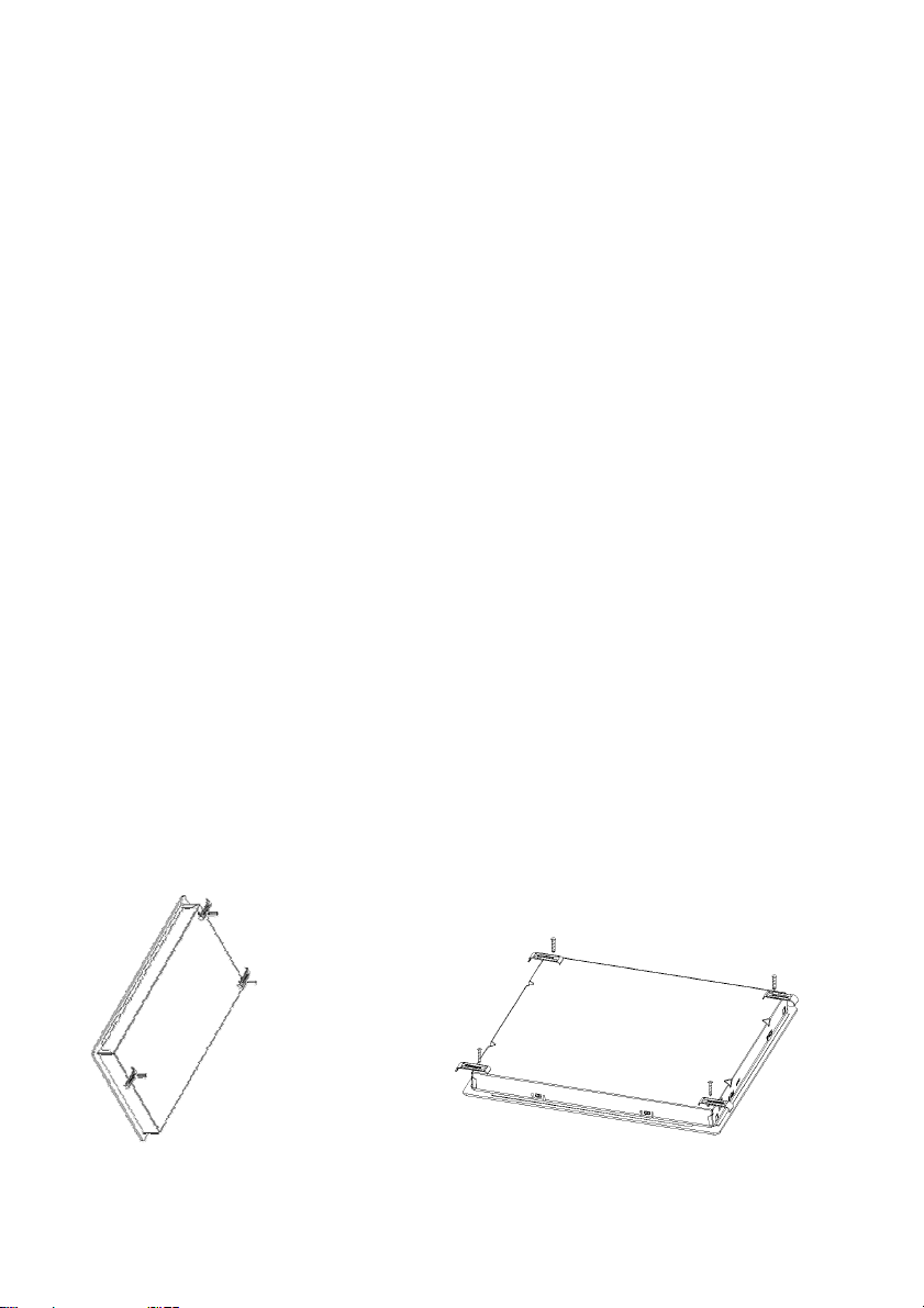
Locating the fixing brackets
• The unit should be placed on a stable, smooth surface (use the packaging). Do not
apply force onto the controls protruding from the cooktop.
• Fix the cooktop on the work surface by screw four brackets on the bottom of
cooktop (see picture) after installation.
• Adjust the bracket position to suit for different work surface’s thickness.
Loading ...
Loading ...
Loading ...