Loading ...
Loading ...
Loading ...
Disconnect the plug
from the power source
before making any assembly,
adjustments or changing accessories.
Such preventive safety measures reduce the
risk of starting the tool accidentally.
For all work or when
changing accessories
always wear protective gloves. Such
preventive safety measures reduce the risk
of injury from sharp edges of the
accessories. Application tools can become
very hot while working. Danger of burns!
INSTALLING ACCESSORIES WITH
EASY-LOCK ACCESSORY CHANGE
Only use Dremel
accessories rated 21000
OPM or greater. Using accessories not
designed for this power tool may result in
serious personal injury and property damage.
The Dremel Multi-Max MM35 was designed
with an integrated accessory change
mechanism. The Easy-Lock accessory
interface allows you to install and remove
accessories without the need of a wrench or
hex key.
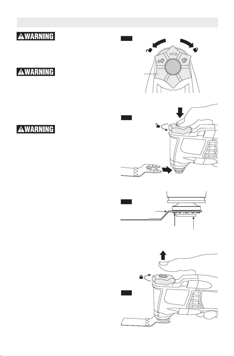
1.To install an accessory using the Easy-
Lock feature, first loosen the clamping
knob by twisting it in a counter-clockwise
direction (Fig. 2).
2.Press the clamping knob so that the
clamping flange extends enough to fit a
blade in between the clamping flange and
the interface. You may need to loosen the
clamping knob more to allow adequate
room for the accessory. (Fig. 3)
3.Place the accessory onto the interface,
making sure the accessory engages all
pins on the interface and the accessory is
flush against the accessory holder (Fig. 4).
4.Release pressure on the clamping knob.
The spring action of the mechanism will
hold the blade in place while you secure it
(Fig. 5).
5.Tighten the clamping knob by twisting in a
clockwise direction (Fig. 2). Make sure to
tighten fully, until you can’t twist the clamping
knob (without it being uncomfortable).
-9-
Assembly
FIG. 3
FIG. 2
Clamping
Knob
Pins
Flange
Accessory
FIG. 5
FIG. 4
1600A014GW MM35 08-18.qxp_MM35 8/23/18 9:06 AM Page 9
Loading ...
Loading ...
Loading ...