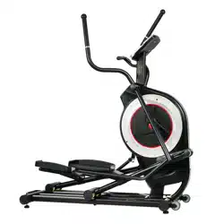
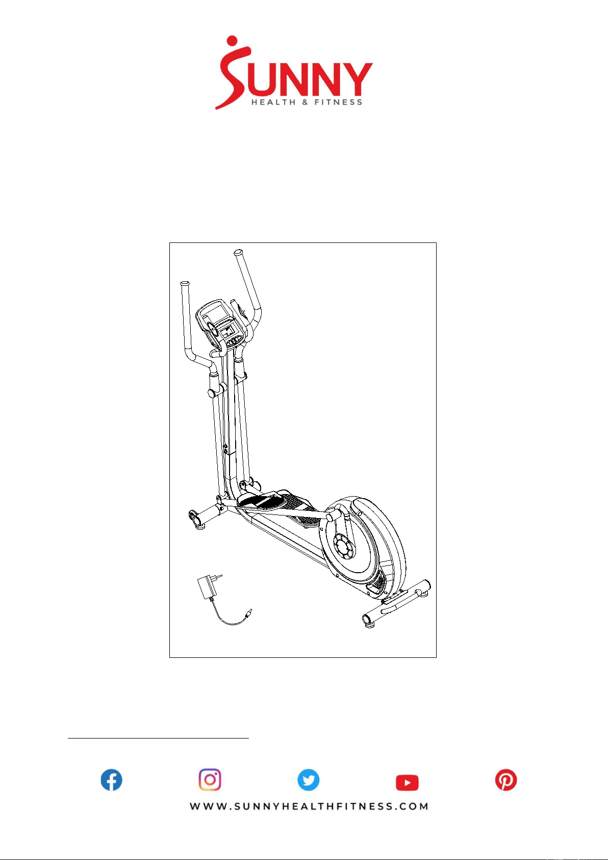
POWER STRIDE ADVANCED
ELLIPTICAL MACHINE
SF-E321006
USER MANUAL
IMPORTANT! Please retain owner’s manual for maintenance and adjustment instructions. Your
satisfaction is very important to us, PLEASE DO NOT RETURN UNTIL YOU HAVE CONTACTED
US: support@sunnyhealthfitness.com or 1- 877 - 90SUNNY (877-907-8669).

1
IMPORTANT SAFETY INFORMATION
We thank you for choosing our product. To ensure your safety and health, please use this
equipment correctly. It is important to read this entire manual before assembling and using the
equipment. Safe and effective use can only be achieved if the equipment is assembled, maintained,
and used properly. It is your responsibility to ensure that all users of the equipment are informed of
all warnings and precautions.
1. Before starting any exercise program, you should consult your physician to determine if you
have any medical or physical conditions that could put your health and safety at risk or prevent
you from using the equipment properly. Your physician’s advice is essential if you are taking
medication that affects your heart rate, blood pressure, or cholesterol level.
2. Be aware of your body’s signals. Incorrect or excessive exercise can damage your health. Stop
exercising if you experience any of the following symptoms: pain, tightness in your chest,
irregular heartbeat, shortness of breath, lightheadedness, dizziness, or feelings of nausea. If
you do experience any of these conditions, you should consult your physician before continuing
with your exercise program.
3. Keep children and pets away from the equipment. The equipment is designed for adult use only.
4. Use the equipment on a solid, flat level surface with a protective cover for your floor or carpet.
To ensure safety, the equipment should have at least 2 feet (60 CM) of free space all around it.
5. Ensure that all nuts and bolts are securely tightened before using the equipment. The safety of
the equipment can only be maintained if it is regularly examined for damage and/or wear and
tear.
6. Always use the equipment as indicated. If you find any defective components while assembling
or checking the equipment, or if you hear any unusual noises coming from the equipment during
exercise, discontinue use of the equipment immediately and do not use until the problem has
been rectified.
7. Wear suitable clothing while using the equipment. Avoid wearing loose clothing that may
become entangled in the equipment.
8. Do not place fingers or objects into the moving parts of the equipment.
9. The maximum weight capacity of this unit is 265 pounds (120 KG).
10. The equipment is not suitable for therapeutic use.
11. To avoid bodily injury and/or damage to the product or property, proper lifting and moving are
required.
12. Your product is intended for use in cool and dry conditions. You should avoid storage in extreme
cold, hot or damp areas as this may lead to corrosion and other related problems.
13. This equipment is designed for indoor and home use only; it is not intended for commercial use.
2
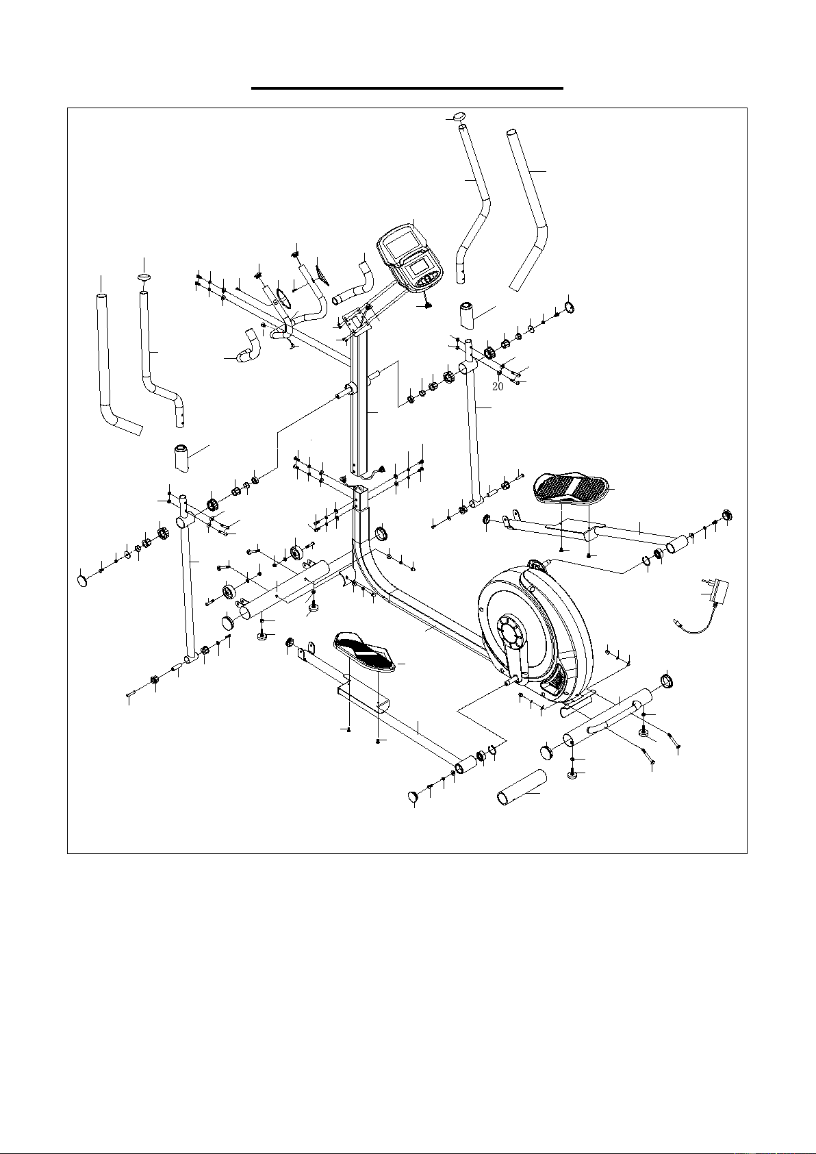
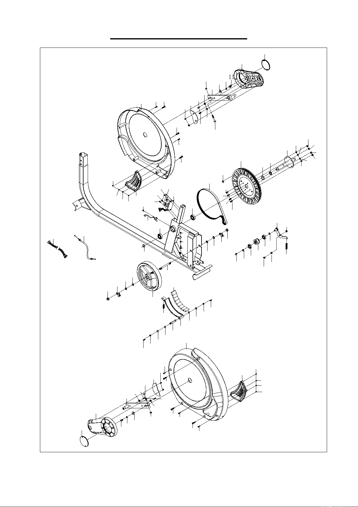
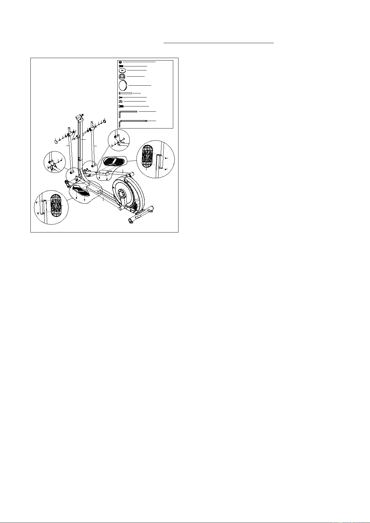
EXPLODED DIAGRAM 1
1a
12
5
5
3
7
41
10
10
10
10
9
9
26L
26R
27
28
28
29
30
31
32
33
34
35
18
35
18
36
36
36
36
37
9
37
37
37
38
38
38
38
45
44L
44R
42
43L
43R
53
53
53
53
11
11
46
47
49
49
51
39
40
39
40
39
40
39
40
50
2
11
1
30
28
28
29
27
31
4
14
14
16
16
20
19
17L
17R
3
6
10
9
11
10
9
11
9
9
11
15
15
18
21
21
22
22
22
23
9
24
24
25
33
34
9
9
46
47
48
48
9
104
13
42
6
8
8
11
21
20
19
21
22
23
25
11
9
18
41
2
2
2
18
18
19
19
20
52
52
52
52
41
41
11
9
9
11
9
11
10
11
9
10
106
3
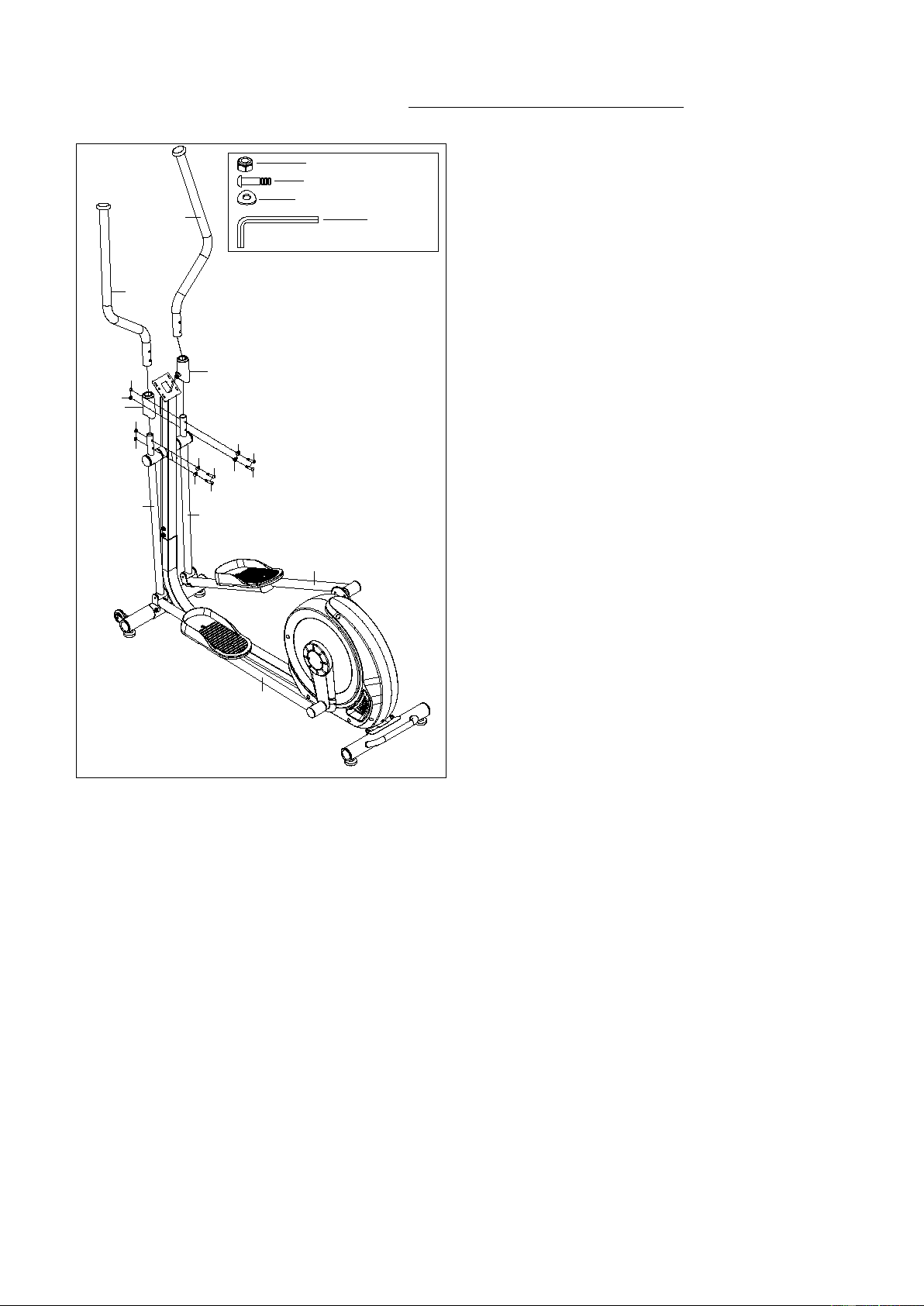
EXPLODED DIAGRAM 2
95
57
57
56
56
54
54
101
59
100
58
55
55
77
31
73
76
70
102
66
65
67
62
64
63
68
69
60
60
86
80
81
82
18
61
65
66
71
72
74
74
75
78
79
80
57
83
56
84
85
31
93
94
95
96
98
49
9
11
99
97
95
92
91
96
88
89
87L
94
95
103
105
95
94
95
94
95
91
92
31
98
97
49
88
9
87R
95
94
90L
94
95
93
90R
89
93
93
93
93
93
93
31
95
31
95
57
57
57
56
56
56
84
84
84
95
95
95
4
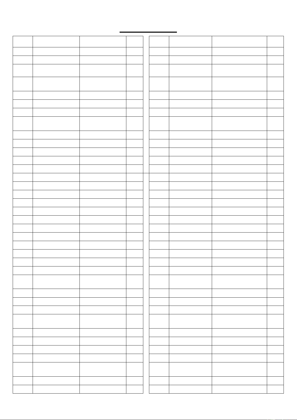
PARTS LIST
No. Description Spec. Qty. No. Description Spec. Qty.
1 Computer 1 37 Nut M8*H16*S13 4
1a Computer Wire 1 38 End Cap Φ60.5*17 4
2 Bolt M5*10 4 39
Adjustable Foot
Pad
4
3
Handle Pulse
Plate
2 40 Nut M8*H6.8*S13 4
4
Middle Handlebar
1
41
Washer
d8*Φ20*2
4
5 Grip Foam 2 42 Round End Cap 2
6 Round End Cap Φ25*16 2 43L/R Pedal 360*160*47 2
7
Handle Pulse
Wire
1 44L/R Pedal Arm 2
8 Bolt ST4.0*19*Φ11 2 45 Main Frame 1
9 Spring Washer d8 18 46 Round End Cap Φ48*18 2
10 Arc Washer d8*Φ20*2*R30 8 47 Bearing 2203 2
11 Bolt M8*20*S5 14 48 C-clip d40 2
12 Handlebar Post 1 49 Washer d8*Φ22*2 4
13 C-clip Φ12*11*Φ3 1
50 Adapter 1
14 Grip Foam 30*5*550 2 51 Rear Stabilizer 1
15 End Cap 32*22*Φ50 2 52 Bushing 4
16 Handlebar Cover 2 53 Bolt M8*12*S5 4
17L/R Handlebar 2 54 C-clip d12 2
18 Nylon Nut M8*H7.5*S13 7 55 Washer d6*Φ12*1.2 2
19 Bolt M8*40*15*S5 4 56 Spring Washer d6 6
20 Arc Washer d8*Φ20*2*R16 4 57 Bolt M6*16*S10 6
21 Bushing 4 58 Tension Spring 1
22 Bushing 4 4 59 Magnetic Plate 1
23 Washer d8*Φ32*2 2 60 Nut M6*H5*S10 2
24 Rubber Bushing Φ30*Φ20*10 2 61 Bolt M6*45*S10 1
25
Handlebar End
Cover
Φ50*5 2 62 Rod of Flywheel 1
26L/R Swing Bar 2 63 Bushing Φ15*Φ10.2*9 1
27 Bolt M8*65*M6*15*S5 2 64 Hexagonal Nut M10*1*H5*S17 1
28 Bushing 3 4 65 Screw M6*40*Φ10*2.5 2
29 Bushing Φ14*Φ8.3*59.5 2 66
Hexagon Thin
Nut
M10*1*H5*S17
2
30 Bolt M6*15*S5 2 67 Flywheel 6KG 1
31 Washer d6*Φ16*1.5 7 68 Taper-face Nut M10*1*H5*S17 1
32 Front Stabilizer 1 69 Wave Washer d10*Φ13.5*0.3 1
33 Bolt M8*42*15*S5 2 70 Tension Spring 1
34
Transportation
Wheel
2 71 Washer d12*Φ17*0.5 1
35 Washer d8*Φ16*1.5 2 72 Bolt M8*12*Φ10*5.5*S5 1
36 Bolt M8*73*20*H5 4 73 Idler 1

5
No. Description Spec. Qty. No. Description Spec. Qty.
74 Bearing 6001 2 92 Bolt ST4*13*Φ8 4
75 Wave Washer d12*Φ15.5*0.3 1 93 Bolt ST4*10*Φ6 8
76 Idler Rod 1 94
Cross
Recessed Pan
Head Self
Drilling Tapping
Screws
ST4.2*16*Φ8 6
77 Bolt M6*12*S10 1 95
Cross
Recessed Pan
Head Tapping
Screws
ST4.2*16*Ф8 14
78 Round Magnet 1 96 Bolt M10*50*20*S17 2
79 Belt 6PJ 430 1 97 Crank 2
80 Bearing 6004 2 98 Nylon Nut M10*H9.5*S17 2
81 C-Clip d20 1 99 Motor 1
82 Wave Washer d21*Φ27*0.3 1 100 Square Magnet 8
83 Axis 1 101
Magnetic Plate
Axle
1
84
Nylon Nut
M6*H6*S10
4
102
Sensor Wire
1
85
Bushing
Φ25*Φ20.2*4
1
103
Power Line
1
86
Belt Plate
1
104
Trunk Wire 1
1
87L/R
Chain Cover
2
105
Trunk Wire 2
1
88
Crank Cover
2
106
Paper Tube
1
89
Small Cover
2
A
Spanner
S5
1
90L/R Decorative Cover 2 B Allen Wrench S13-14-15 1
91
Crank Close
Plate
2 C Spanner S5 1
6
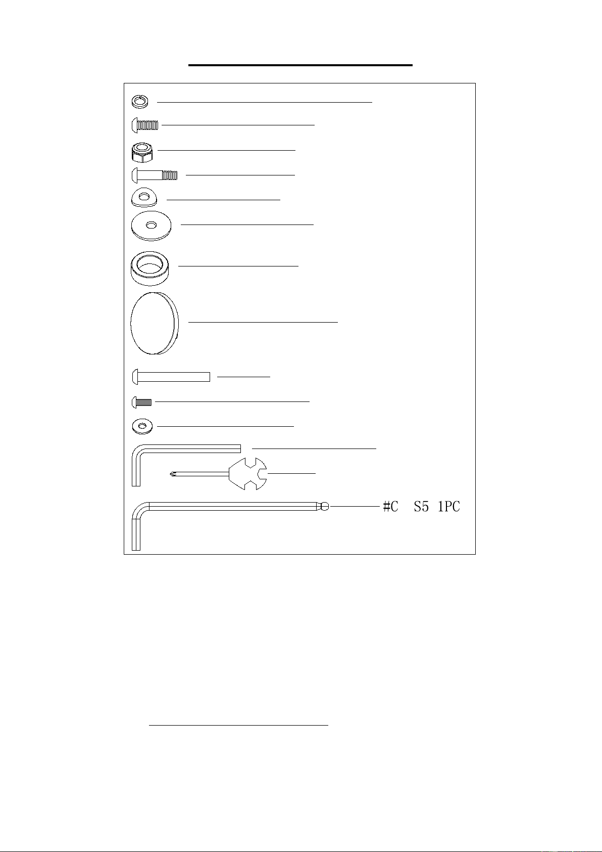
HARDWARE PACKAGE
#9 d8 2PCS
#11 M8*20*S5 2PCS
#19 M8*40*15*S5 4PCS
#18 M8*H7.5*S13 4PCS
#20 d8*
Φ
20*2*R16 4PCS
#23 d8*
Φ
32*2 2PCS
#24
Φ
30*
Φ
20*10 2PCS
#25
Φ
50*5 2PCS
#27 M8*65*M6*15*S5 2PCS
#30 M6*15*S5 2PCS
#31 d6*
Φ
16*1.5 2PCS
#A S5 1PC
#B S13-14-15 1PC
Ordering Replacement Parts (U.S. and Canadian Customers only)
Please provide the following information in order for us to accurately identify the part(s) needed:
The model number (found on cover of manual)
The product name (found on cover of manual)
The part number found on the “EXPLODED DIAGRAM” and “PARTS LIST” (found near the front
of the manual)
Please contact us at support@sunnyhealthfitness.com or 1- 877 - 90SUNNY (877-907-8669).
7
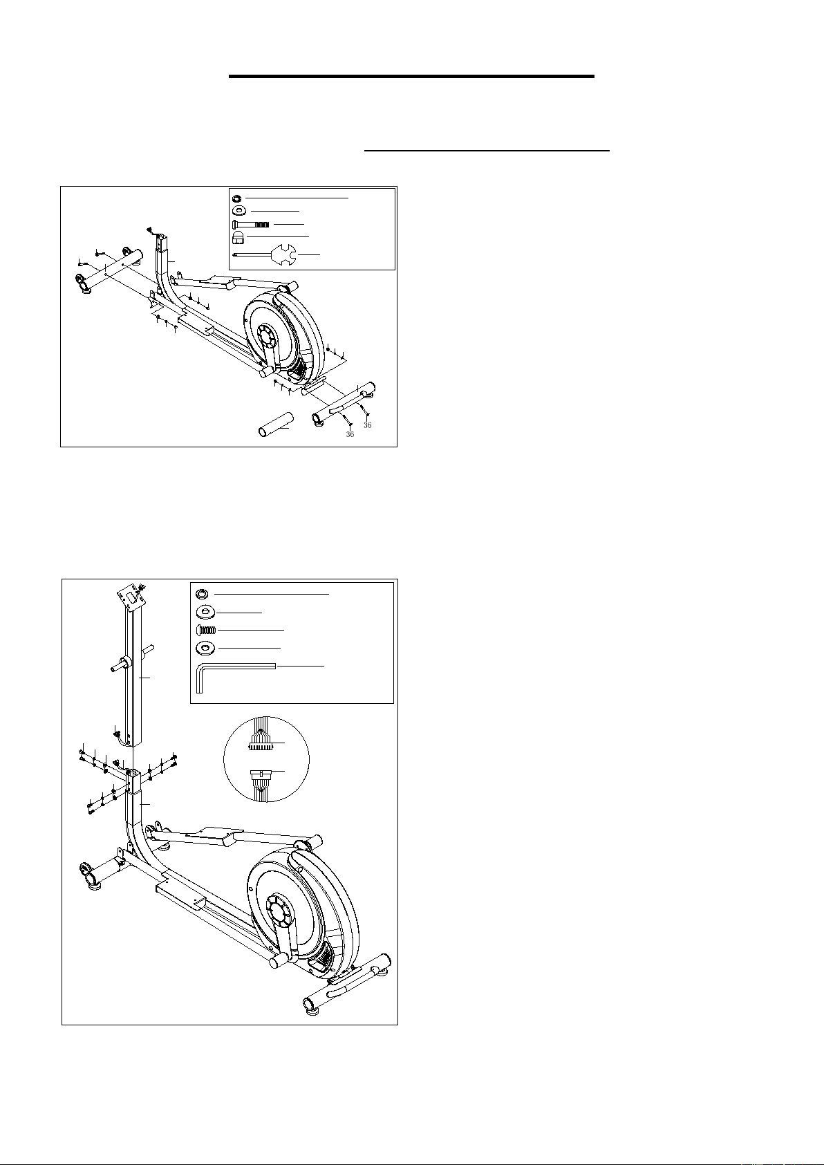
ASSEMBLY INSTRUCTIONS
We value your experience using Sunny Health and Fitness products. For assistance with parts or
troubleshooting, please contact us at support@sunnyhealthfitness.com or 1-877-90SUNNY
(877-907-8669).
10
9
37
36
45
37
9
10
32
36
#37 M8*H16*S13 4PCS
#9 d8 4PCS
#36 M8*73*20*H5 4PCS
#B S13-14-15 1PC
10
10
9
9
37
37
51
#10
d8
*
Φ
20*2*R30 4PCS
106
11
10
9
41
104
45
105
104
12
105
41
9
9
#9 d8 6PCS
#11 M8*20*S5 6PCS
#A S5 1PC
11
11
#10 d8*
Φ
20*2*R30 2PCS
#41 d8*
Φ
20*2 4PCS
STEP 1:
Remove 4 Bolts (No. 36), 4 Arc Washers (No.
10), 4 Spring Washers (No. 9) and 4 Nuts (No.
37) and Paper Tube (No. 106) from the Main
Frame (No. 45) and Front Stabilizer (No. 32)
by Allen Wrench (No. B).
Attach the Front Stabilizer (No. 32) and Rear
Stabilizer (No. 51) to the Main Frame (No. 45)
using 4 Bolts (No. 36), 4 Arc
Washers (No.
10), 4 Spring Washers (No. 9) and 4 Nuts (No.
37)
that were removed. Tighten and secured
with Allen Wrench (No. B).
STEP 2:
Remove 6 Bolts (No. 11), 2 Arc Washers (No.
10), 6 Spring Washers (No. 9) and 4 Washers
(No. 41) from Main Frame (No. 45) by Spanner
(No. A).
Connect Trunk Wire 1 (No. 104) with Trunk
Wire 2 (No. 105) well.
Insert Handlebar Post (No. 12) into Main
Frame (No. 45), then tighten and secure with 6
Bolts (No. 11), 2 Arc Washers (No. 10), 6
Spring Washers (No. 9) and 4 Washers (No.
41) that were removed by Spanner (No. A).
8
We value your experience using Sunny Health and Fitness products. For assistance with parts or
troubleshooting, please contact us at support@sunnyhealthfitness.com or 1-877-90SUNNY
(877-907-8669).
26L
26R
27
30
31
27
23
9
24
23
9
11
25
24
31
30
44L
44R
Ⅰ
Ⅱ
12
11
25
#9 d8 2PCS
#11 M8*20*S5 2PCS
#A S5 1PC
#27 M8*65*M6*15*S5 2PCS
#30 M6*15*S5 2PCS
#23 d8*
Φ
32*2 2PCS
#24
Φ
30*
Φ
20*10 2PCS
#25
Φ
50*5 2PCS
#31 d6*
Φ
16*1.5 2PCS
#C S5 1PC
#53 M8*12*S5 4PCS
Ⅲ
Ⅳ
53
53
43R
43L
53
53
STEP 3:
Remove 4 Bolts (No. 53) from Pedals (No.
43L/R) by Spanner (No. C), fix
Pedals (No.
43L/R) to Pedal Arms (No. 44L/R) with 4 Bolts
(No. 53) that were removed by Spanner (No. C)
as shown in pictureⅠ&Ⅱ.
Insert 2 Rubber Bushings (No. 24) in
Handlebar Post (No. 12) first, then tighten and
secure Swing Bars (No. 26L/R) to Handlebar
Post (No. 12) with 2 Bolts (No. 11), 2 Washers
(No. 23) and 2 Spring Washers (No. 9) by
Spanner (No. A) or Spanner (No. C). Fasten 2
Handlebar End Covers (No. 25) to Swing
Bars (No. 26L/R).
Tighten and secure Pedal Arms (No. 44L/R) to
Swing Bars (No. 26L/R) with 2 Bolts (No. 27),
2 Bolts (No. 30) and 2 Washers (No. 31) by
Spanner (No. A) and Spanner (No. C) as
shown in picture Ⅲ&Ⅳ.
9
We value your experience using Sunny Health and Fitness products. For assistance with parts or
troubleshooting, please contact us at support@sunnyhealthfitness.com or 1-877-90SUNNY
(877-907-8669).
17R
44R
44L
26L
26R
17L
18
18
16
16
19
19
20
20
19
20
19
20
18
18
#A S5 1PC
#18 M8*H7.5*S13 4PCS
#19 M8*40*15*S5 4PCS
#20 d8*
Φ
20*2*R16 4PCS
STEP 4:
Insert 2 Handlebar Covers (No. 16) into
Handlebars (No. 17L/R), secure Handlebars
(No. 17L/R) into Swing Bars (No. 26L/R) with 4
Bolts (No. 19), 4 Arc Washers (No. 20) and 4
Nylon Nuts (No. 18) by Spanner (No. A).
10
We value your experience using Sunny Health and Fitness products. For assistance with parts or
troubleshooting, please contact us at support@sunnyhealthfitness.com or 1-877-90SUNNY
(877-907-8669)
10
9
11
2
104
4
104
1a
7
50
#9 d8 2PCS
#11 M8*20*S5 2PCS
#A S5 1PC
#2 M5*10 4PCS
#B S13-14-15 1PC
12
45
#10
d8
*
Φ
20*2*R30 2PCS
7
11
9
10
1a
1
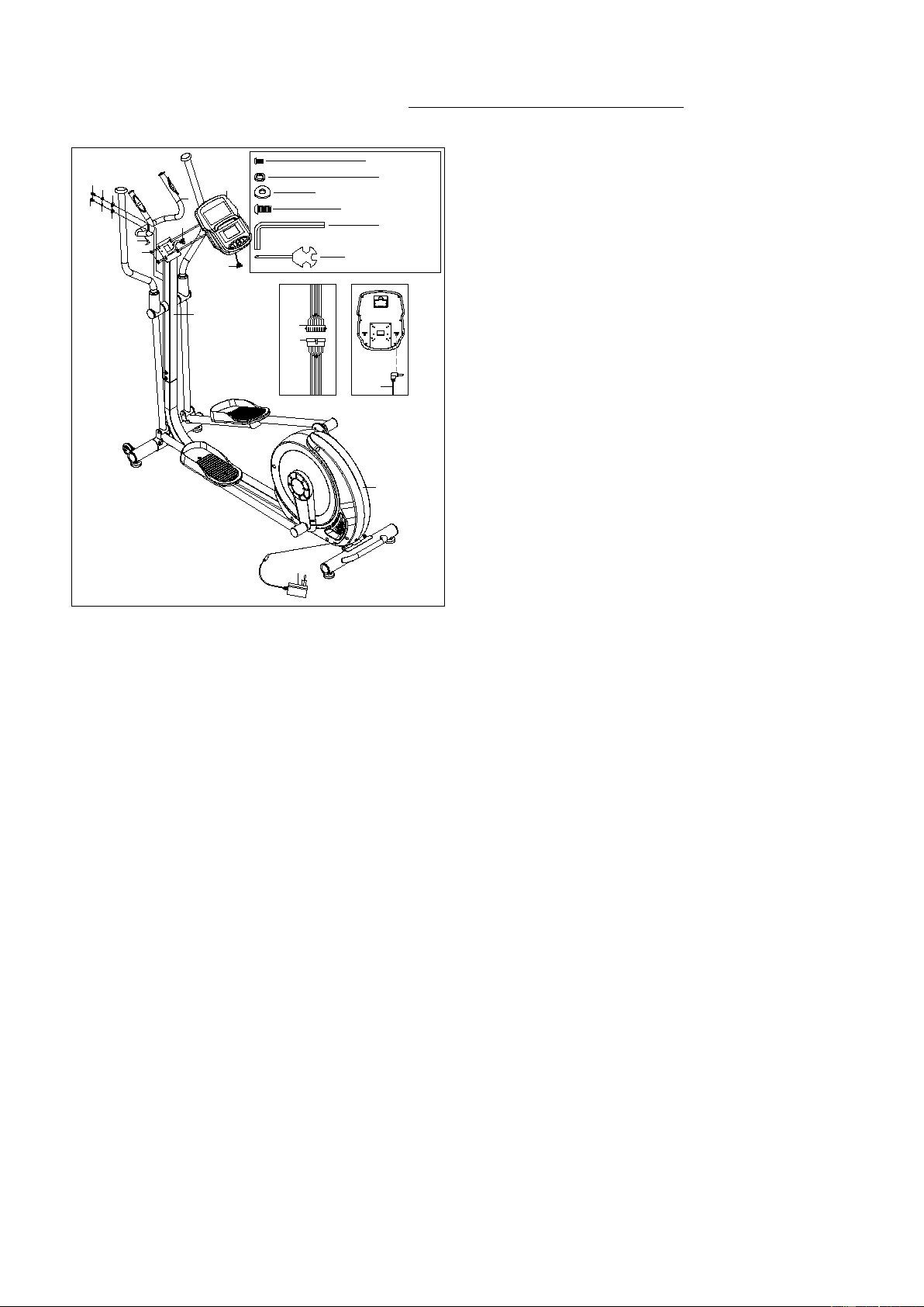
STEP 5:
Remove 4 Bolts (No. 2) from Computer (No.
1).
Connect Trunk Line 1 (No. 104) with
Computer Wire (No. 1a) well.
Attach Computer (No. 1) on Handlebar Post
(No. 12) with 4 Bolts (No. 2) that were removed
by Allen Wrench (No. B).
Remove 2 Bolts (No. 11), 2 Spring Washers
(No. 9) and 2 Arc Washers (No. 10) from
Handlebar Post (No. 12) by Spanner (No. A),
fix Middle Handlebar (No. 4) to Handlebar
Post (No. 12) with 2 Bolts (No. 11), 2 Spring
Washers (No. 9) and 2 Arc Washers (No. 10)
that were removed by Spanner (No. A).
Insert Handle Pulse Wire (No. 7) to the hole on
the back of Computer (No. 1).
Insert the line of Adapter (No. 50) into adapter
input hole on the back of Main Frame (No. 45)
and plug the Adapter (No. 50) into an outlet.
Attention:
Switch off the power when not in
use.
The assembly is complete!
11
ADJUSTMENTS & USAGE GUIDE
34
51
32
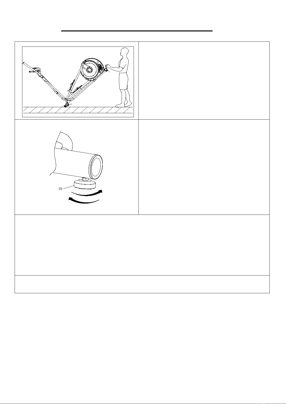
MOVING THE ELLIPTICAL
To move the elliptical, lift up Rear Stabilizer (No.
51) until the Transportation Wheels (No. 34) on
the Front Stabilizer (No. 32)
touch the ground.
With the Transportation Wheels (No. 34) on the
ground, you can transport the elliptical to the
desired location with ease.
ADJUSTING THE BALANCE
In order to achieve a smooth and comfortable
ride, you must ensure that the elliptical is stabled
and secured. If you notice that the elliptical is
unbalanced during use, you should adjust the
Adjustable Foot Pads (No. 39) located beneath
the front and rea
r stabilizers. To do so, simply
rotate the Adjustable Foot Pads (No. 39) until
the elliptical becomes levelled with the floor
surface.
CLEANING
The elliptical can be cleaned with a soft, clean, damp cloth. Do not use abrasives or solvents on
plastic parts
. Please wipe your perspiration off the elliptical after each use. Be careful not to get
excessive moisture on the computer display panel as this might cause electrical hazard or
electronics to fail.
Please keep the elliptical, especially the computer, out of direct sunlight to prevent screen damage.
Please inspect all assembly bolts and pedals on the elliptical for proper tightness every week.
STORAGE
Store the elliptical in a clean and dry environment, away from children.
12
IMPORTANT ELECTRICAL INFORMATION
WARNING:
This elliptical requires a power source of 1 amp (100-240V) in order to properly operate. For your
safety, as well as the safety of others, please verify that the power source is correct before plugging
in the elliptical. Any power source above or below this level could cause significant damage to the
elliptical and or user.
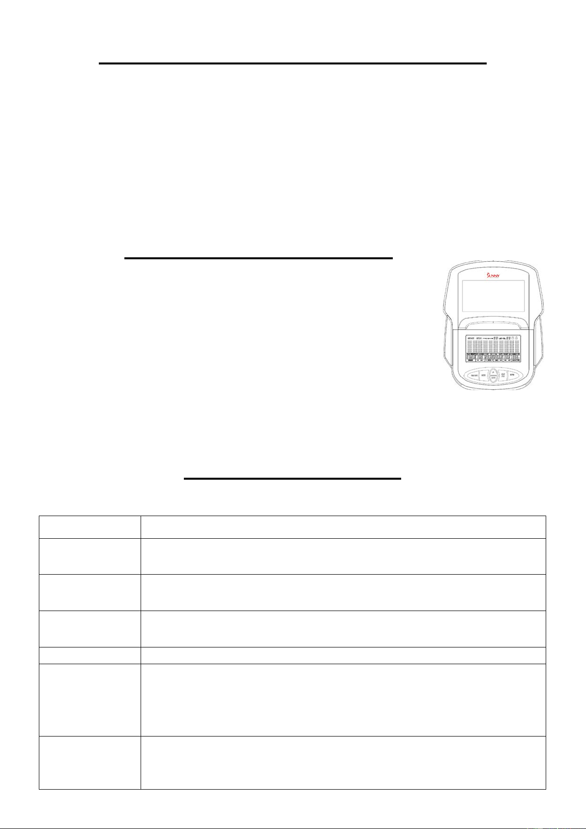
OPERATING INSTRUCTIONS
Plug the AC adaptor into the elliptical and into the outlet.
The computer will turn on.
The computer will turn off if there is no activity for 4 minutes. Press any
button on the computer to turn it on again.
NOTE: You can still use the elliptical when it is not plugged in. However, the
computer will not be working, and you cannot adjust the resistance level or use any of the functions.
EXERCISE COMPUTER
KEY FUNCTIONS:
KEY FUNCTION
START/STOP
Start and pause workouts.
Start body fat measurement.
DOWN
Lower the resistance level during workout.
Decrease value of selected parameter.
UP
Increase the resistance level during workout.
Increase value of selected parameter.
ENTER
To input the value or mode.
RECOVERY
Enter Recovery function when computer displays the heart rate value.
Recovery displays F1-F6.
F1 is poor recovery heart rate.
F6 is excellent recovery heart rate.
MODE
During workout, switch display from RPM to SPEED, ODO to DIST and
WATT to CALORIES.
Hold for 3 seconds to reset all function values to zero.

13
WORKOUT SELECTION:
After turning the computer on by plugging in the AC adaptor or if already plugged in, pressing any
button on the computer, use the UP or DOWN button to make a selection. Then press ENTER
button to choose the desired mode.
There are 7 basic workout modes:
Manual, Pre-program, Watt Program, Body Fat Program, Target Heart Rate Program, Heart Rate
Control Program, and User Program.
FUNCTIONS:
SPEED: Displays current training speed. Maximum speed is 99.9 MPH.
RPM: Displays current rotation per minute.
TIME: Accumulates the workout time from 00:00 to 99:59. Users can preset the target time they
want.
DIST: Accumulates the workout distance from 0.00 up to 999.9 miles. Users can preset the target
distance they want to reach.
ODO: Displays the total accumulated distance from 0 to 9999 miles.
CAL: Accumulates the calories burned from 0 to 9999. Users can preset the target calories they
want to burn.
WATT: Displays current watt.
HEART RATE: Displays the current heart rate in beats per minute.
TARGET HR.: Users can preset their Target Heart Rate.
PROGRAM: There are 24 different programs to choose for training.
LEVEL: The program has 10 columns of bars and 8 bars in each column. Each column represents
a 1-minute workout and each bar represents 2 resistance levels.
WORKOUT PARAMETERS:
TIME / DISTANCE / CALORIES / AGE / WATT / TARGET HEART RATE
Setting Workout Parameters
After selecting the desired workout mode: Manual Program, Pre-set Program, Watt Control
Program, Body Fat Program, Target Heart Rate Program, Heart Rate Control Program, and User
Program. You may pre-set several workout parameters for desired results.
Note: Some parameters are not adjustable in certain programs. Time and Distance cannot
be set up at the same time.
Once a program has been selected, press ENTER and TIME will flash.
Using the UP or DOWN button, you may select the desired time value. Press ENTER to input the
values. The flashing prompt will move to the next parameter. Continue using the UP or DOWN
button. Press the START/STOP button to begin the workout.
14
More About Workout Parameters
Field Setting Range
Default
Value
Increment/
Decrement
Description
Time 0:00~99:00 00:00 ±1:00
1. When display is set as 0:00,
Time will count up.
2. When time is set as 1:00-99:00,
it will count down to 0.
Distance 0.00~999.0 0.00 ±1.0
1. When display is set as 0.0,
Distance will count up.
2. When Distance is set as
1.0~999.0, it will count down to 0.
Calories 0~9995 0 ±5
1. When display is set as 0,
Calories will count up.
2. When Calories is set as 5~9995,
it will count down to 0.
Watt 50~250 100 ±5
User can set watt value only in the
Watt Control Program.
Age 10~99 30 ±1
Target HR will be based on Age.
When Heart Rate exceeds Target
HR, the Heart Rate number will
flash.
Pulse 60~220 90 ±1
Setting Parameters for Target
heart rate.
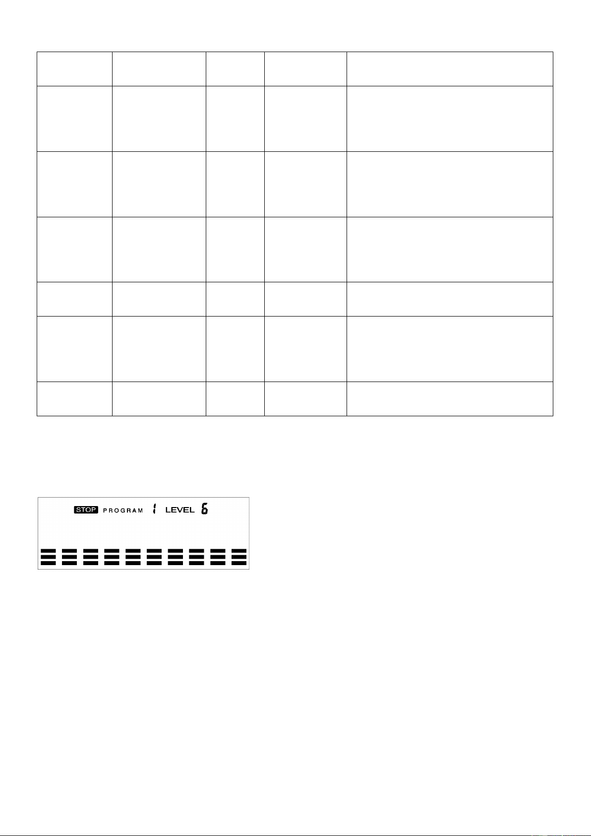
PROGRAM OPERATION
:
Manual (P1)
Program profile
SETTING PARAMETERS FOR MANUAL PROGRAM
1. Select Manual Program (P1) using the UP or DOWN button, then press ENTER.
2. TIME will flash so the value can be adjusted using the UP or DOWN button.
3. Press the ENTER button to save the value and move to the next parameter to be adjusted.
Note: If you set up the target time for workout, then the next parameter of Distance
cannot be adjusted.
4. Continue through all desired parameters and press the START/STOP button to begin the
workout.
Note: Once the workout parameter counts down to zero, it will beep and stop the
workout automatically. Press the START button to continue the workout to reach the
unfinished workout parameter.
15
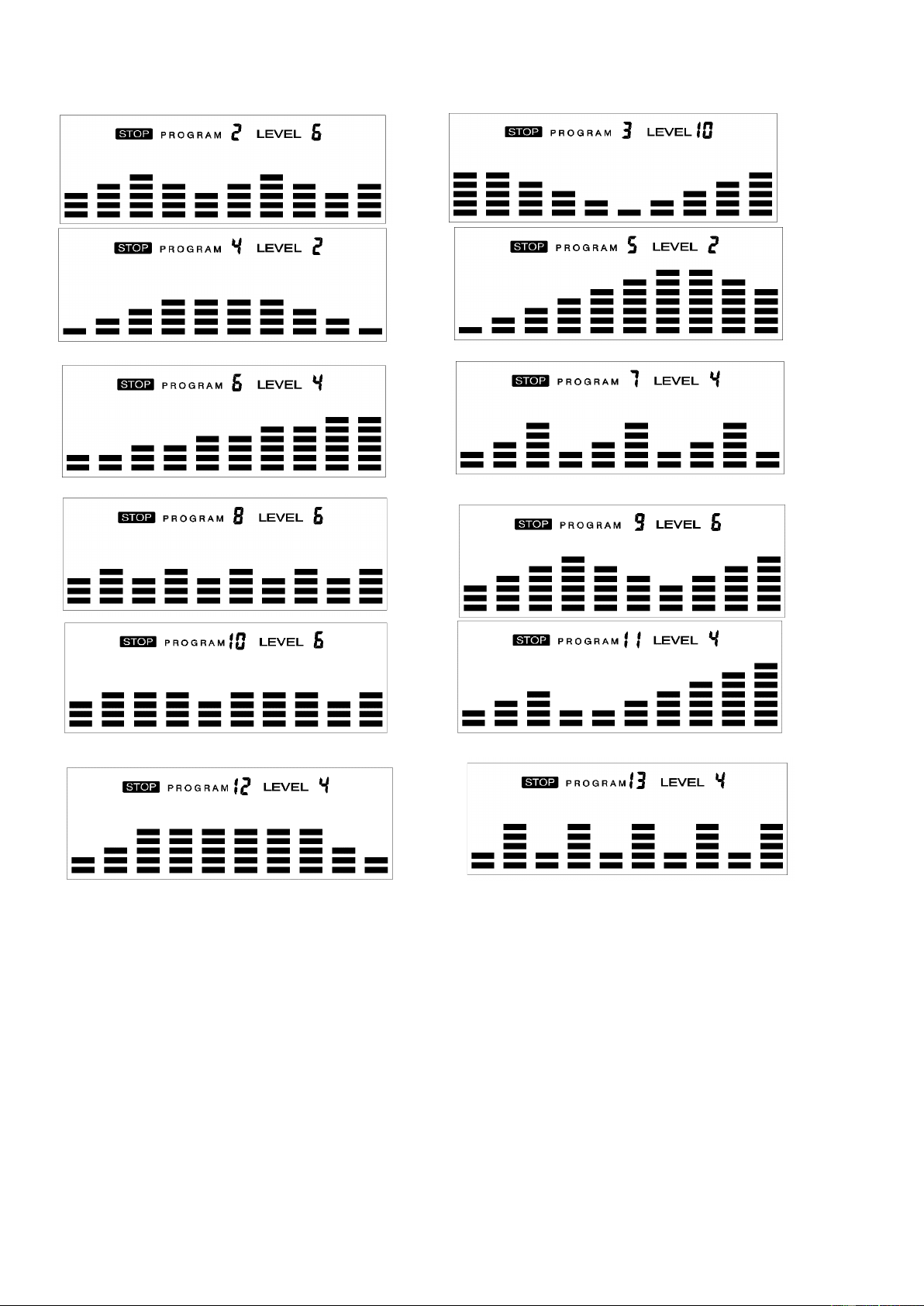
Pre-set programs (P2~P13)
Program profile
There are 12 pre-set programs ready for use. All program profiles have 16 levels of resistance.
SETTING PARAMETERS FOR PRE- SET PROGRAMS
1. Select one of the Pre-set Programs using the UP or DOWN button, then press ENTER. TIME
will flash so the value can be adjusted using the UP or DOWN button.
2. Press the ENTER button to save value and move to the next parameter to be adjusted.
Continue through all desired parameters, pressing the START/STOP button to begin the
workout.
Workout in any pre-set program
You can adjust the level of resistance by pressing the UP or DOWN button during the workout.
16
Note: If you set up the target time for workout, then the next parameter of Distance cannot
be adjusted. Once the workout parameter counts down to zero, it will beep and stop the
workout automatically. Press the START button to continue the unfinished parameter.
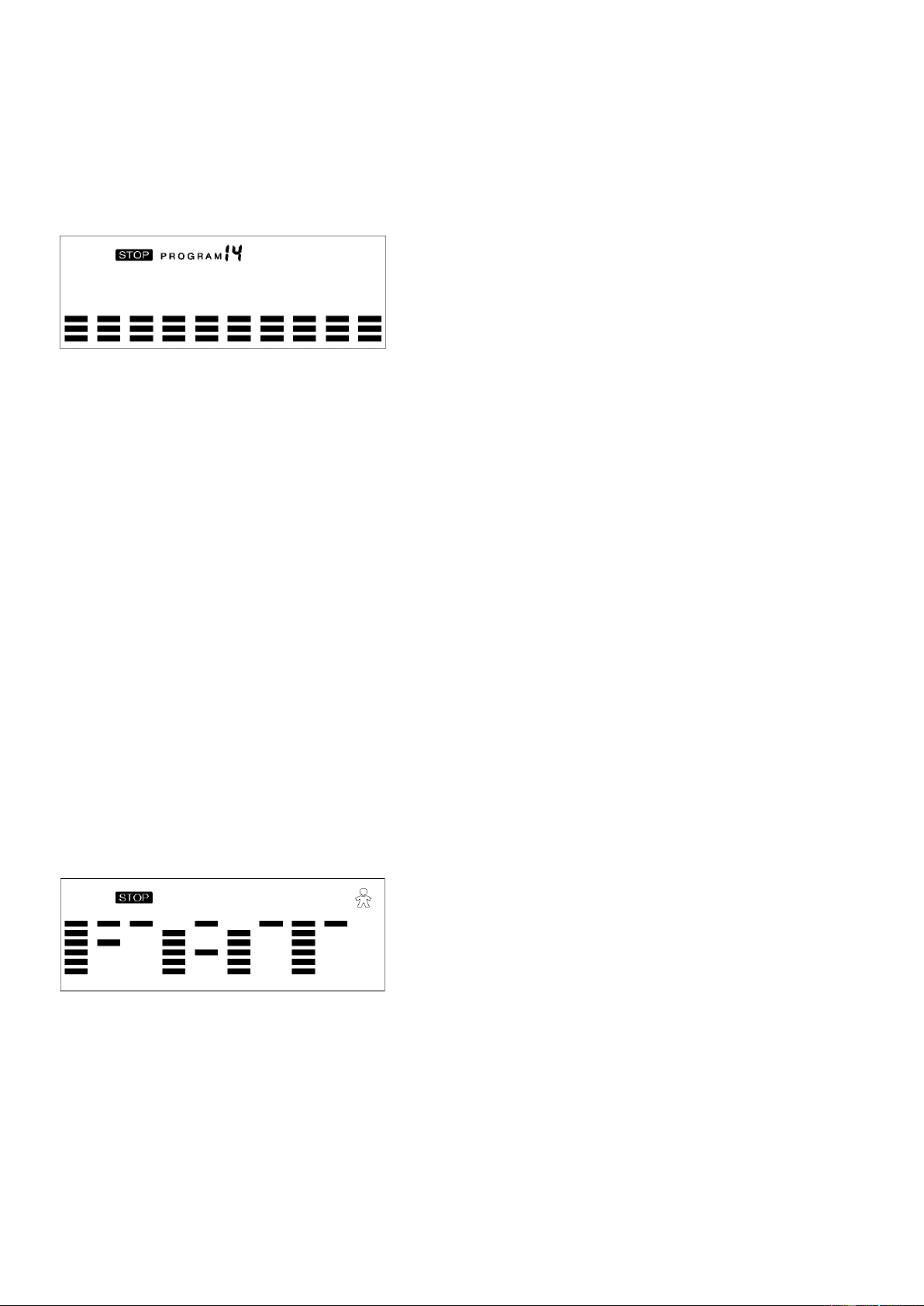
Watt Control Program (P14)
Program profile
SETTING PARAMETERS FOR THE WATT CONTROL PROGRAM
1. Select Watt Control Program (P14) using the UP or DOWN button, then press ENTER.
2. TIME will flash so the value can be adjusted using the UP or DOWN button.
3. Press ENTER button to save the value and move to the next parameter to be adjusted.
Note: If you set up the target time for workout, then the next parameter of Distance
cannot be adjusted.
4. Continue through all desired parameters, pressing the START/STOP button to start the
workout.
Note: Once the workout parameter counts down to zero, it will beep and stop the
workout automatically.
5. Press the START button to continue the workout to reach the unfinished workout parameter.
The computer will adjust the resistance load automatically depending on the speed to
maintain the constant watt value. You can use the UP or DOWN button to adjust the watt
value during the workout.
BODY FAT Program (P15)
Program profile
SETTING DATA FOR BODY FAT
Select BODY FAT Program (P15) using the UP or DOWN button, then press ENTER. “MALE” will
flash so Gender can be adjusted using the UP or DOWN button. Press the ENTER button to save
gender and move to the next data.
“5’8 (inches)” of Height will flash so Height can be adjusted using the UP or DOWN button. Press
ENTER to save the value and move to the next data.
17
“154 (lbs)” of Weight will flash so Weight can be adjusted using the UP or DOWN button. Press
ENTER to save the value and move to the next data.
“30” of Age will flash so Age can be adjusted using the UP or DOWN button. Press ENTER to save
the value.
Press the START/STOP button to start the measurement. Please also remember to grasp the hand
pulse grips. After 15 seconds the display will show Body Fat %, BMR, BMI, & BODY TYPE.
Body Types:
There are 9 body types divided according to the FAT % calculated.
Body Type
FAT %
Body Type
FAT %
Body Type
FAT %
Type 1
5% - 9%
Type 4
20% - 24%
Type 7
35% - 39%
Type 2
10% - 14%
Type 5
25% - 29%
Type 8
40% - 44%
Type 3
15% - 19%
Type 6
30% - 34%
Type 9
45% - 50%
BMR: Basal Metabolism Ratio
BMI: Body Mass Index
Press START/STOP button to return the main display.
TARGET HEART RATE Program (P16)
Program profile
SETTING PARAMETERS FOR TARGET HEART RATE PROGRAM
1. Select TARGET HEART RATE Program (P16) using the UP or DOWN button, then press
ENTER.
2. TIME will flash. The value can be adjusted using the UP or DOWN button.
3. Press the ENTER button to save the value and move to the next parameter to be adjusted.
Note: If you set up the target time to workout, then the next parameter of Distance
cannot be adjusted.
4. Continue through all desired parameters, pressing START/STOP button to start workout.
Note: If Pulse is above the set TARGET HR, the Pulse value will flash to remind the user.
18
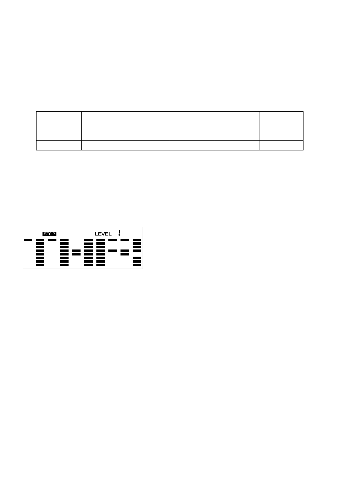
HEART RATE CONTROL Program (P17-P20)
Program profile
There are 4 selections for target pulse (HR):
HRC - 55% TARGET HR= 55% of (220-AGE)
HRC - 65% TARGET HR= 65% of (220-AGE)
HRC - 75% TARGET HR= 75% of (220-AGE)
HRC - 85% TARGET HR= 85% of (220-AGE)
SETTING PARAMETERS FOR HEART RATE CONTROL
1. Select one of the Heart Rate Control Programs using the UP or DOWN button, then press
ENTER.
2. TIME will flash. The value can be adjusted using the UP or DOWN button.
3. Press the ENTER button to save the value and move to the next parameter to be adjusted.
Note: If t you set up the target time to work out, then the next parameter of Distance
cannot be adjusted.
4. Continue through all desired parameters, pressing the START/STOP button to start the
workout.
Note: If Pulse is above or below (± 5) the TARGET HR, the computer will adjust the
resistance load automatically. It will check every 20 seconds approx. 1 resistance load
will increase or decrease (Note: each resistance load represents 2 levels of loading).
If one of the workout parameter counts down to be zero, it will beep and stop the
workout automatically. Press the START/STOP button to continue the workout to reach
unfinished workout parameter.
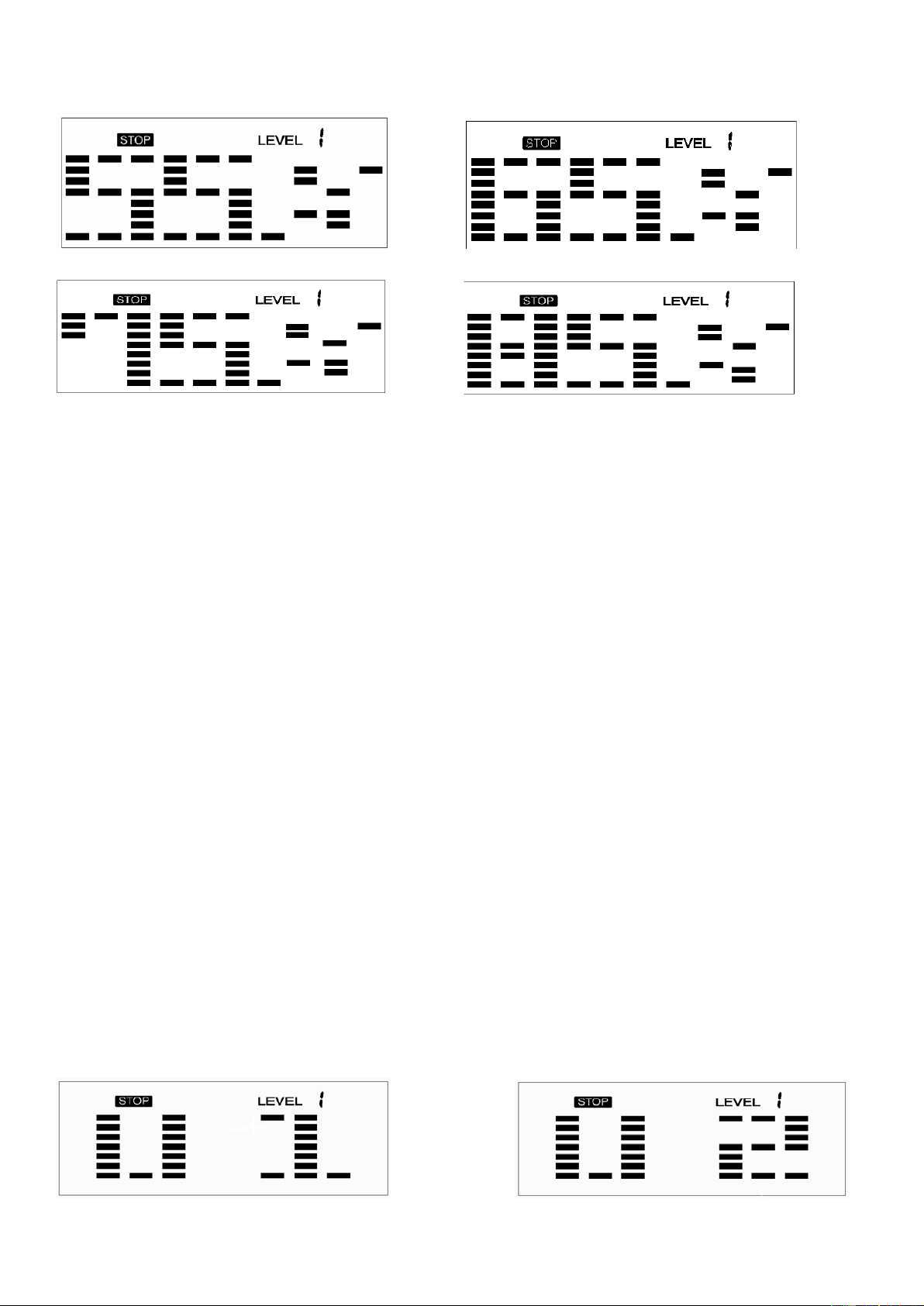
User Program
Program profile (P21-P24)
19
The 4 user programs allow the user to set their own program that can be used immediately.
SETTING PARAMETERS FOR USER PROGRAM
1. Select the User Program using the UP or DOWN button then press ENTER.
2. TIME will flash so the value can be adjusted using the UP or DOWN button.
3. Press the ENTER button to save the values and move to the next parameter to be adjusted.
Note: If the user sets up the target time to workout, then the next parameter for Distance
cannot be adjusted.
4. Continue through all desired parameters.
5. After finishing the setup of the desired parameters, level 1 will flash. Use the UP or DOWN
button to adjust, then press the ENTER button until finished. (There are 10 times total). Press
the START/STOP button to begin the workout.
Note: Once the workout parameter counts down to zero, it will beep and stop the
workout automatically. Press the START/STOP button to continue the workout to reach
the unfinished workout parameter.
APP CONNECTION
1. Scan the QR code below to enter the app store and download the SunnyFit app to your mobile
phone.
2. Ensure that the Bluetooth function is turned on from your phone.
3. If this is your first time using the SunnyFit app, follow the in-app instructions to register for your
free SunnyFit account and log in.
4. To connect the equipment to the SunnyFit app:
a) From the “Workout” tab, press on the “Search” button to search for your equipment.
b) Once your equipment appears on the list, tab on the “Select” button.
c) Note: If your equipment does not appear on the “Searching for Equipment” list, check the
EXERCISE COMPUTER on your equipment to ensure that it is not in sleep mode and
your phone’s Bluetooth function is on, then tap “Retry” to search again.
d) Once your equipment shows up on the “Workout” tab as “Currently Selected”, that means
it is now ready to display, track, and record your workout stats on the app!

20
TROUBLESHOOTING
PROBLEM POSSIBLE CAUSE CHECK SOLUTION
E1
The motor doesn’t work.
Check if the motor wires are
plugged in or check if the motor
is stuck.
Plug in the motor wires
again or change the motor.
There is something wrong
with the cables.
Check if the cables are
damaged. This can cause a
short circuit.
Change the cables or plug
in again.
The computer cannot
supply normal voltage to
the motor.
Test whether the voltage of the
motor is normal
when pressing
UP or DOWN button.
Change the computer.
E2
The IC (Integrated
Circuits) inside the
computer is damaged.
Change the computer.
E4
Hands aren’t put on the
two hand pulse sensors
immediately after pressing
START.
Put the hands on the two
hand pulse sensors
immediately after pressing
START.
Body Fat Function cannot
receive the signal for
pulse.
Check if the hand pulse
sensor wires are well
connected.
Plug in the hand pulse
sensor wires again or
change the hand pulse
sensor wires.
Check if the pulse is working
when not in Body Fat program.
Change the computer.
NOTE: If you are unable to resolve an issue using the troubleshooting guide above, please
contact Customer Service at [email protected]om.
Version 1.0