Loading ...
Loading ...
Loading ...
Page 6
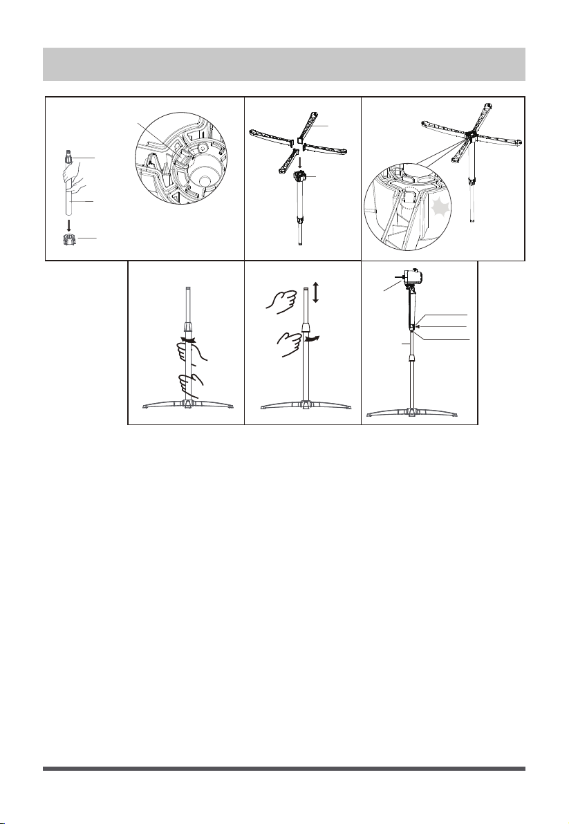
ASSEMBLY OF STAND & EXTENSION POLE
Thumb screw
Cross base
connector
Stand
Pa!
Fig.6
Height
adjustment
ring
Pole assembly
Cross base connector
Observation hole
Screw installation hole
Mounting hole
Fig.1 Fig.2 Fig.3
Fig.4 Fig.5
1. Insert the pole assembly into the cross base connector from top to
bottom, ensure it is installed in place (use the observation hole to
determine if the pole assembly is fully inserted into the cross base
connector).(Fig.1)
2. Insert 4 stands into the cross base connector. Ensure the stands are
well fixed into the cross base connector.(Fig.2,3)
3. From the extension pole, loosen the height adjustment ring and
adjust the internal pole to the desired height. (Note: If you can’t find
the internal pole, it slides inside the extension pole. You can pull it
out from the extension pole.) Fasten the height adjustment
ring.(Fig.4,5)
4. To attach the head unit to the internal pole, loosen the thumb screw
(separate screw driver needed) on the bottom of the head unit.
Place the head unit on the internal pole and tighten the thumb screw
in alignment with the groove and mounting hole on the internal pole.
(Fig.6)
Tighten
Loosen
Head unit
Internal pole
Loading ...
Loading ...
Loading ...