Loading ...
Loading ...
Loading ...
Installation Instructions
DIRECT CONNECT APPLICATIONS
[] MAKE WIRE LEAD CONNECTIONS INSIDE THE JUNCTION BOX
1. Make all wire connections bv using al_l_ropriate UiAisted electrical connecto_ and techniques.
2. Select the applicable wiring situation and tbllow the instructions accordingly:
1-Phase 220-240 VAC
1_Twn_o,r_e(:/i,_"//w Zone&w /o a si,@.J)hasv cir(ui@.
230V a/qdicalio_,_:
Omnect the white and black leads ot the Zoneline
power sui)ply kit to the branch circuit 1,1 and 1,2
leads. (The white lead of the power sui)ply kit should
be identified by the installer using electrical tape with
some color other than green or white.) Cmmect the
green lead ot the power sui)ply kit to the power
sui)ply and branch circuit gmtmd.
3-Phase 208 VAC
IUu,, (o,necti,g" the Zondim: to a thweJdu¢,v: ci*vuitJbr
208V a/qdicatio,,_:
Connect the white and black leads ot the Zoneline
power supply kit to the branch drcuit 1,1 and 1,2
leads. (The white lead of the power supply kit should
be identified by the installer using electrical tape with
some color other than green or white,) Connect the
green lead of the power supply kit to the power
supply and branch circuit ground.
3-Phase 208 VAC with "Crazy Leg"
//7wn _onn_(ling" the _mdine 10a gmu@hasv ci*_uit wilh
"(;mzr L_¢"Jbr 208V ap/)lk:ation,_:
Connect the white and black leads of the Zoneline
power supply kit to the branch drcuit Neutral and 1,1
leads. (The white lead d the power supply kit should
be com_ected to neutral.) Cmmect the green lead of
the power supply kit m the power supply and branch
circuit grotmd.
3-Phase 253-277 VAC
IIIw. _onrwcii,g" the 7_mdim_ lo a lh*_u@hasvcimuitJbr
265V ap/dicalio,s:
Connect the white and black leads of the Zoneline
power supply kit to the branch circuit Neutral and 1,1
leads. (The white lead d the power supply kit should
be connected to neutral.) Connect the green lead of
the power supply kit to the power supply and branch
circuit grotmd.
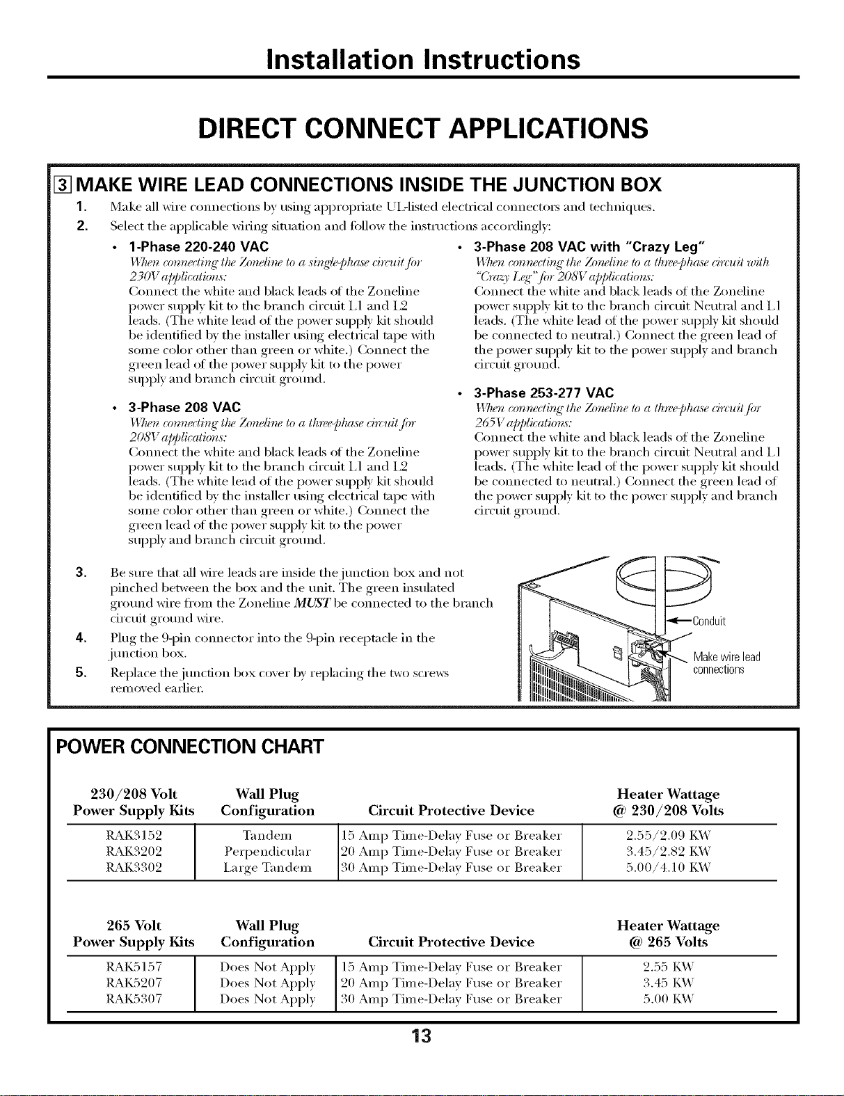
3. Be sure that all wire leads are inside thejtmction box and not
pinched between the box and the trait. The green insulated
grotmd wire from the Zoneline MUST be com_ected to the branch
circuit grotmd wire.
4. Plug the 9-pin c(mnector into the 9-pin receptacle in the
junction box.
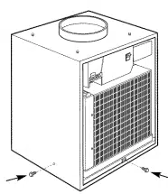
5. Replace the junction box cover by replacing the two scre_vs
removed earlier:
bnduit
Makewirelead
connections
POWER CONNECTION CHART
230/208 Volt
Power Supply Kits
RAK3152
RAK3202
RAK3302
Wall Plug
Configuration
T_I n den/
Perpendicular
i,arge Tandem
Circuit Protective Device
15 Amp Time-Delay Fuse or Breaker
20 Amp Time-Delay Fuse or Breaker
30 Amp Time-Delay Fuse or Breaker
Heater Wattage
Ca)230/208 Volts
2.55/2.09 I_A_'
3.45/2.82 I_A_'
5.00/4.10 I_A_'
265 Volt Wall Plug Heater Wattage
Power Supply Kits Configuration Circuit Protective Device @ 265 Volts
RAK5157 Does Not Apply 15 Amp Time-Delay Fuse or Breaker 2.55 K_'
RAK5207 Does Not Apply 20 Amp Time-Delay Fuse or Breaker 3.45 K_'
RAK5307 Does Not Apply 30 Amp Time-Delay Fuse or Breaker 5.00 K_'
13
Loading ...
Loading ...
Loading ...