Loading ...
Loading ...
3
Installation
RESET
STATU
S
CONFIG
A
B
A
RE
SET
STATUS
CONFIG
C
D
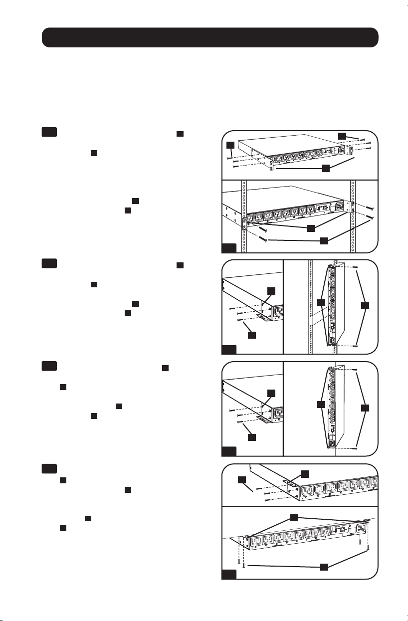
Mounting the PDU
The PDU supports five primary mounting configurations: 1U Rack, 0U Rack (Vertical), Wall,
Under-Counter and Reduced-Depth.
Note: Regardless of configuration, the user must determine the fitness of hardware and procedures before mounting. The PDU and
included hardware are designed for common rack and rack enclosure types and may not be appropriate for all applications. Exact
mounting configurations may vary. Screws for attaching the mounting brackets to the PDU are included. Use only the screws
supplied by the manufacturer, or their exact equivalent (#6-32, 3/16" flat head).
1-1
1U Rack Mounting: Use 3 screws
A
to
attach each of the 2 longer mounting
brackets
B
to the PDU as shown. You can
mount the PDU in a recessed position by
attaching the mounting brackets so they
extend beyond the front panel of the PDU.
Mount the PDU in the rack by inserting 4
user-supplied screws
C
through the
mounting brackets
D
and into the
mounting holes of the rack rails.
1-2
0U Rack Mounting: Use 3 screws
A
to
attach each of the 2 shorter mounting
brackets
B
to the PDU as shown. Mount
the PDU vertically by inserting 2 or more
user-supplied screws
C
through the
mounting brackets
D
and into mounting
points in the rack or rack enclosure.
1-3
Wall Mounting: Use 3 screws
A
to attach
each of the 2 shorter mounting brackets
B
to the PDU as shown. Mount the PDU to
the wall by inserting 2 or more user-
supplied screws
C
through the mounting
brackets
D
and into secure mounting
points.
1-4
Under-Counter Mounting: Use 3 screws
A
to attach each of the 2 shorter
mounting brackets
B
to the PDU as
shown. Mount the PDU under the counter
by inserting 2 or more user-supplied
screws
C
through the mounting brackets
D
and into secure mounting points.
1-1
A
B
C
D
A
B
C
D
A
B
C
D
1-2
1-3
1-4
Loading ...
Loading ...
Loading ...