
USER MANUAL
MANUALE D’USO
BEDIENUNGSANLEITUNG
MQ 80P
DIFFUSORE COMPATTO
A DUE VIE PER INTERNO/
ESTERNO AD ALTA
EFFICIENZA E DIRETTIVITÀ
CONTROLLATA
TWO-WAY HI-EFFICIENCY
DIRECTIVITY CONTROLLED
COMPACT INDOOR /
OUTDOOR SPEAKER SYSTEM
HOCHEFFIZIENTER
ZWEIWEGE-
KOMPAKTLAUTSPRECHER
MIT KONTROLLIERTER
RICHTWIRKUNG
FÜR INNEN- UND
AUSSENANWENDUNGEN

2
ENGLISH
SAFETY PRECAUTIONS
IMPORTANT NOTES
WARNING
IMPORTANT NOTES
Before connecting and using this product, please read this instruction manual
carefully and keep it on hand for future reference. The manual is to be
considered an integral part of this product and must accompany it when it
changes ownership as a reference for correct installation and use as well as
for the safety precautions.
RCF S.p.A. will not assume any responsibility for the incorrect installation and
/ or use of this product.
WARNING: To prevent the risk of fire or electric shock, never expose this
loudspeaker to rain or humidity and dust, but the case this has been expressly
designed and made to get a suitable IP protection grade (indicated in the
product specifications).
SAFETY PRECAUTIONS
1. All the precautions, in particular the safety ones, must be read with
special attention, as they provide important information.
2. Loudspeaker lines (amplifier outputs) can have a sufficiently high voltage
(i.e. 100 V) to involve a risk of electrocution: never install or connect this
loudspeaker when the line is alive.
3. Make sure all connections have been made correctly and the loudspeaker
input voltage (in a constant voltage system) or its impedance is suitable for
the amplifier output.
4. Protect loudspeaker lines from damage; make sure they are positioned in a
way that they cannot be stepped on or crushed by objects.
5. Make sure that no objects or liquids can get into this product, as this may
cause a short circuit.
6. Never attempt to carry out any operations, modifications or repairs that
are not expressly described in this manual.
Contact your authorized service centre or qualified personnel should any of
the following occur:
- the loudspeaker does not function (or works in an anomalous way);
- the cable has been damaged;
- objects or liquids have got into the unit;
- the loudspeaker has been damaged due to heavy impacts / fire.
7. Should the loudspeaker emit any strange odours or smoke, remove it
from the line after having switched the amplifier off.
8. Do not connect this product to any equipment or accessories not foreseen.
For suspended installation, only use the dedicated anchoring points and do
not try to hang this loudspeaker by using elements that are unsuitable or not
specific for this purpose.
Also check the suitability of the support surface to which the product
is anchored (wall, ceiling, structure, etc.), and the components used for

3
ENGLISH
attachment (screw anchors, screws, brackets not supplied by RCF etc.),
which must guarantee the security of the system / installation over time, also
considering, for example, the mechanical vibrations normally generated by
transducers.
9. RCF S.p.A. strongly recommends this product is only installed
by professional qualified installers (or specialised firms) who
can ensure a correct installation and certify it according to the
regulations in force.
The entire audio system must comply with the current standards
and regulations regarding electrical systems.
10. There are numerous mechanical and electrical factors to be considered
when installing a professional audio system (in addition to those which
are strictly acoustic, such as sound pressure, angles of coverage, frequency
response, etc.).
11. HEARING LOSS
Exposure to high sound levels can cause permanent hearing loss. The acoustic
pressure level that leads to hearing loss is different from person to person
and depends on the duration of exposure. To prevent potentially dangerous
exposure to high levels of acoustic pressure, anyone who is exposed to these
levels should use adequate protection devices. When a transducer capable of
producing high sound levels is being used, it is therefore necessary to wear
ear plugs or protective earphones.
See the technical specifications in the instruction manual for the maximum
sound pressure the loudspeaker is capable of producing.
12. To ensure a correct musical reproduction, loudspeaker phase is to be
respected (loudspeakers are connected respecting the amplifier polarity).
This is important when loudspeakers are installed adjacent one another, for
instance, in the same room.
13. To prevent inductive effects from causing hum, noise and a bad system
working, loudspeaker lines should not be laid together with other electric
cables (mains), microphone or line level signal cables connected to amplifier
inputs.
14. The loudspeaker cable shall have wires with a suitable section (twisted,
if possible, to reduce inductive effects due to surrounding electro-magnetic
fields) and a sufficient electrical insulation.
OPERATING PRECAUTIONS
- Install this loudspeaker far from any heat source.
- Do not overload this product for extended periods of time.
- Never force the control elements (keys, knobs, etc. ).
- Do not use solvents, alcohol, benzene or other volatile substances for
cleaning the external parts of this product.
- If the speaker is used in particulary cold places, drive it with a low signal for
5-10 minutes before using it at maximum power.
OPERATING PRECAUTIONS
4
ENGLISH
DESCRIPTION
RCF S.P.A. WOULD LIKE TO THANK YOU FOR HAVING PURCHASED THIS
PRODUCT, WHICH HAS BEEN DESIGNED TO GUARANTEE RELIABILITY
AND HIGH PERFORMANCE.
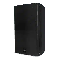
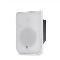
MQ 80P is a two way horn-loaded speaker system that belongs to MONITOR
Q series. Its high quality, high efficiency and compact design make it the ideal
solution to get clear voice and music reproduction in mid-size environments.
It is suitable for both paging and background music.
Thanks to its 90°x 60° directivity, it can be combined into clusters of two or
three pieces to get wide and smooth coverage and to reduce the installation
points.
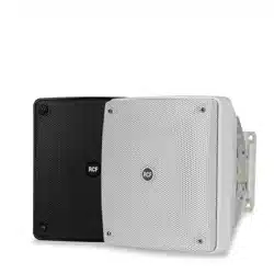
It is suitable for both indoor and (after closing the reflex ports) outdoor
installations (IP 55). The woofer is a high-excursion, epoxy coated paper cone
– rubber surround design mounted in a tuned enclosure (port can be sealed
for outdoor installation).
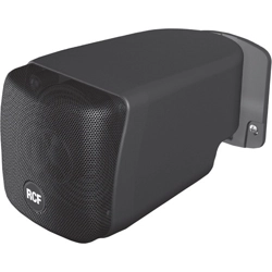
The tweeter is a horn-loaded compression driver with phase plug.
Its installation is quick thanks to the unique bracket with several fixing points
and aiming facilities.
Electrical connections are made by means of a bipolar cable.
Wattage taps (and 8-ohm operation) are selectable by means of a rotary
switch accessible under a sealed cover.
The enclosure is constructed of high density UV resistant polystyrene with a
stainless steel grill.
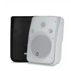
MQ 80P is available in three colours: white (MQ 80P-W), black (MQ 80P-B).
Loudspeakers are to be installed by qualified
personnel, respecting all safety standards.
Loudspeakers are to be installed securely. Make
sure the support structure (walls / ceilings) has
the necessary mechanical characteristics for the
loudspeaker weight, without the risk of a fall that
could damage things or cause an injury. Fix steel
safety cables to loudspeakers.
Use attachment elements suitable for walls /
ceilings (e.g. screw anchors for bricks, screw
anchors for concrete, etc.).
INSTALLATION NOTES

5
ENGLISH
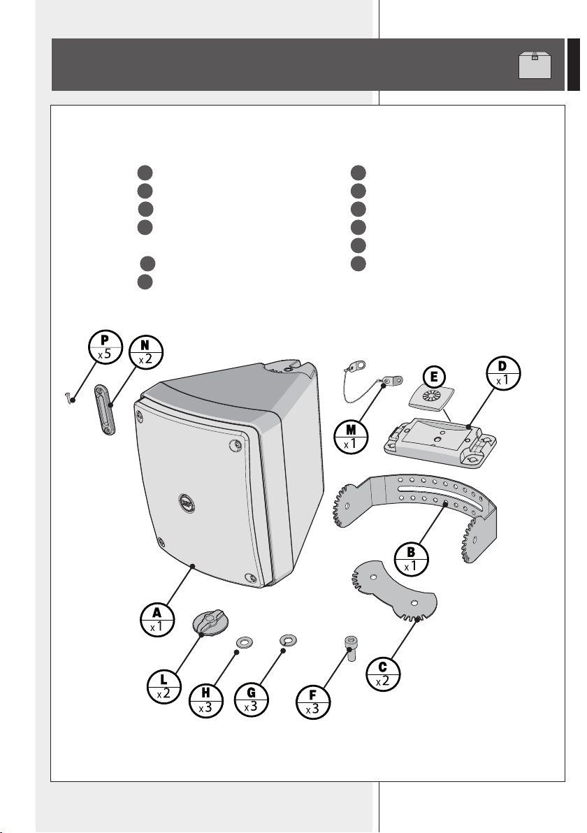
IN THE PACKAGING
-
A
loudspeaker MQ 80P
-
B
“U” bracket
-
C
linking support (x 2)
-
D
complete mounting accessory (with a
bolt) for the “U” bracket +
-
E
plastic plate
-
F
bolt (x3)
-
G
washer (x3)
-
H
washer (x3)
-
L
round knob / bolt (x 2)
-
M
safety steel cable
-
N
reflex plug (x 2)
-
P
screw (x5)
The drilling TemplaTe is in This manual
6
ENGLISH
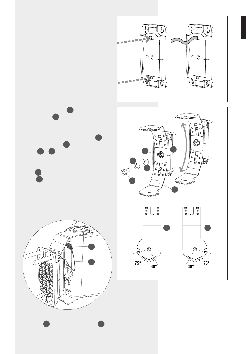
INDOOR / OUTDOOR
SINGLE LOUDSPEAKER INSTALLATION
As default, MQ 80P is a bass-reflex lou speaker for indoor
use. Yet, it can be also used outdoor (protection grade:
IP 55) if adapted as a closed box:
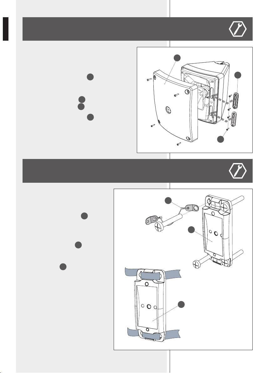
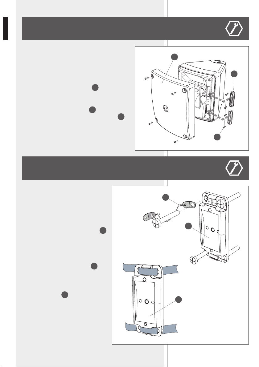
- Take off the loudspeaker grille
S
by removing the
four screws.
- Cover the two reflex ports (holes) by mounting the two
plugs with rubber packings
N
, each to be fixed with
two thread-forming screws
P
.
- Re-mount the loudspeaker grille
S
.
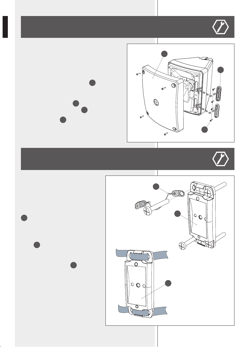
A single loudspeaker can be installed to a wall
either horizontally (coverage angle: 90° hor. x
60° vert.) or vertically (60° hor. x 90 vert.).
First fix the mounting accessory
D
to the wall
through four M8 screws (not included, as these
shall be chosen according to their support).
Fix the steel safety cable to the mounting
accessory (by using a screw)
M
.
If the loudspeaker is installed vertically, the
mounting accessory
D
can be also fixed to a
pole by using two (up and down) clamping 13
mm (or ½”, 12.7 mm) stainless steel bands.
x4
S
N
P
D
D
M
7
ENGLISH
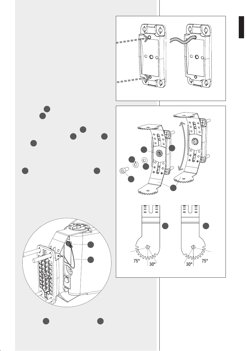
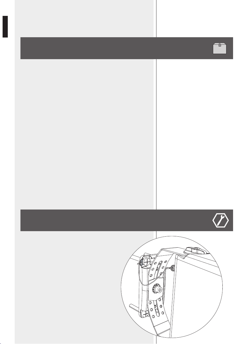
To get a weatherproof electrical connections and
reduce the visible / external part of the loudspeaker
cable (1 m long), this can pass through the “U”
bracket , the mounting accessory hole (to be opened
by pressing the plastic in one of the two available
points) and its back seat, then inserted into the wall
niche* (behind the mounting accessory) that houses
electrical connections.
*It must be weatherproof
in outdoor applications
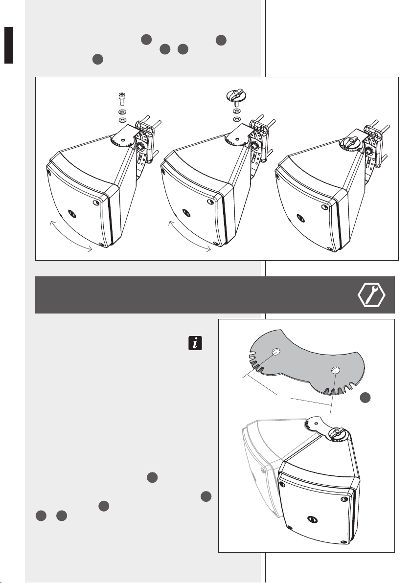
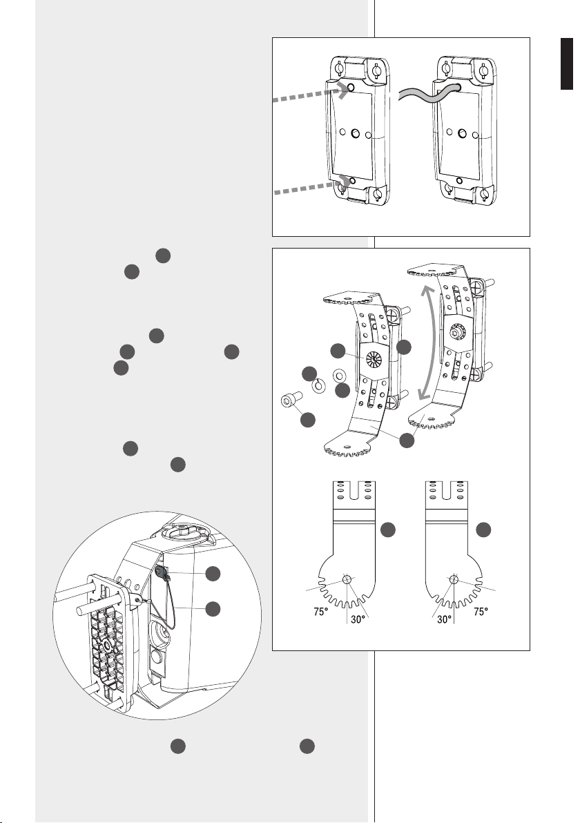
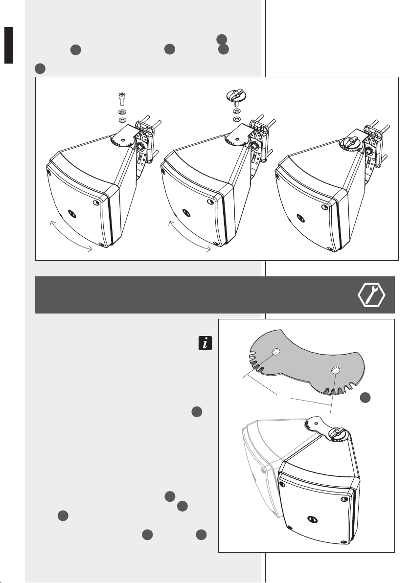
Put the “U”
B
bracket on the mounting
accessory
D
and choose the right vertical*
aiming angle (± 30°; each hole is a 7.5° step),
then fix it by tightening the bolt
F
through
the dedicated plastic plate
E
and washer
G
and
H
.
The “U” bracket allows a horizontal* loudspeaker
aiming either 30° to the right / 75° to the left
a
or 75° to the right / 30° to the left
b
,
according to its position.
Every step is about 15°.
* noTe: assuming The loudspeaker is insTalled verTically.
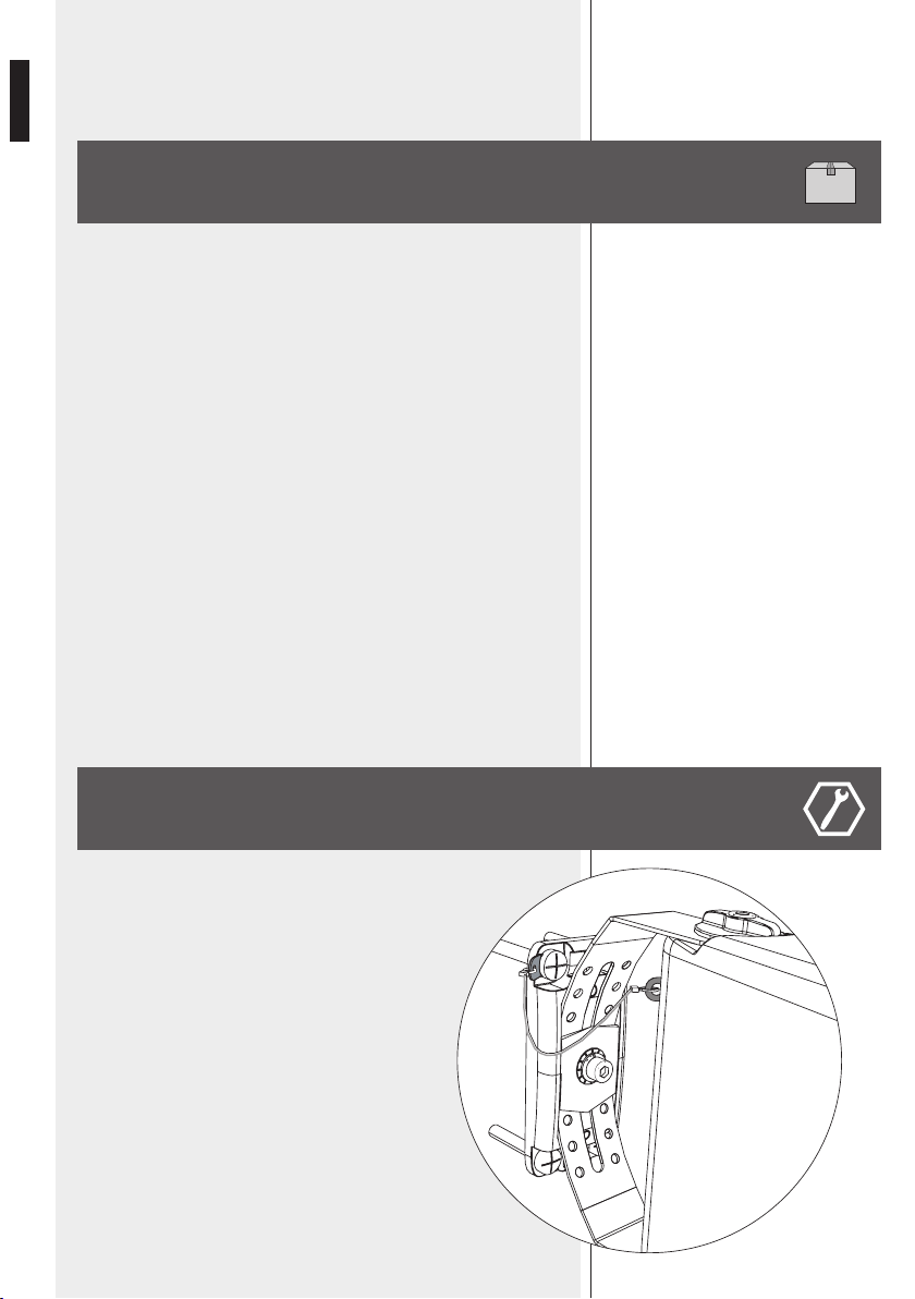
Use a screw
P
to fix the safety steel cable
M
as shown in this example.
E
G
D
H
F
a b
B
P
M
8
ENGLISH
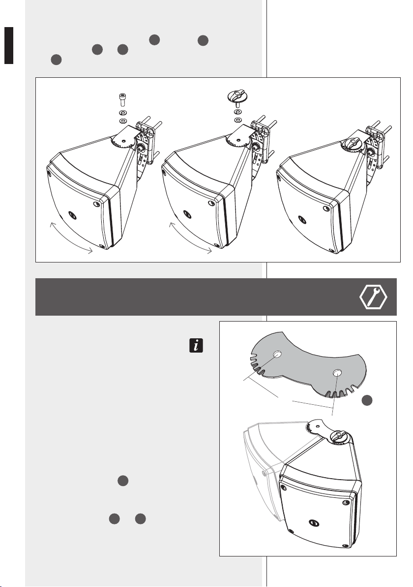
Insert the loudspeaker into the “U” bracket, aim it to the proper direction and
fix it by tightening the two round knobs
L
or two bolts
F
(up and down),
throug the washers
G
and
H
.
Bolts
F
are strongly suggested for outdoor installations.
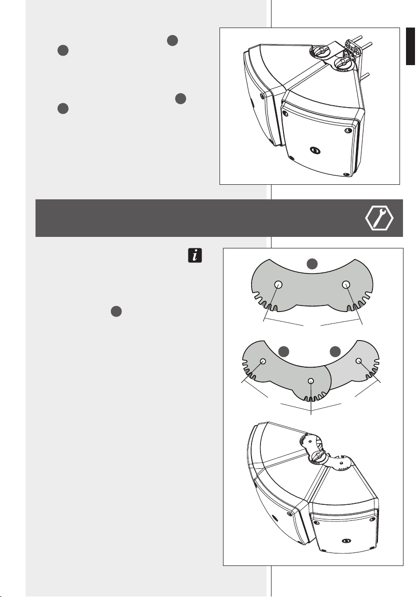
TWO LOUDSPEAKER CLUSTER
noTe: for safeTy reasons, The clusTer shall be
made horizonTally only (by puTTing TogeTher Two
loudspeakers in verTical posiTion).
Install the mounting accessory and the “U” bracket (see the
previous paragraph “Single loudspeaker installation”)
It is necessary to use two linking supports (up and down) to
make the two loudspeaker cluster.
To fix the two loudspeakers and get the optimal 45° angle
between their axes (in order to get an uniform coverage), use
the three spaces between teeth (of both sides, here pointed
out in grey) closer to the centre.
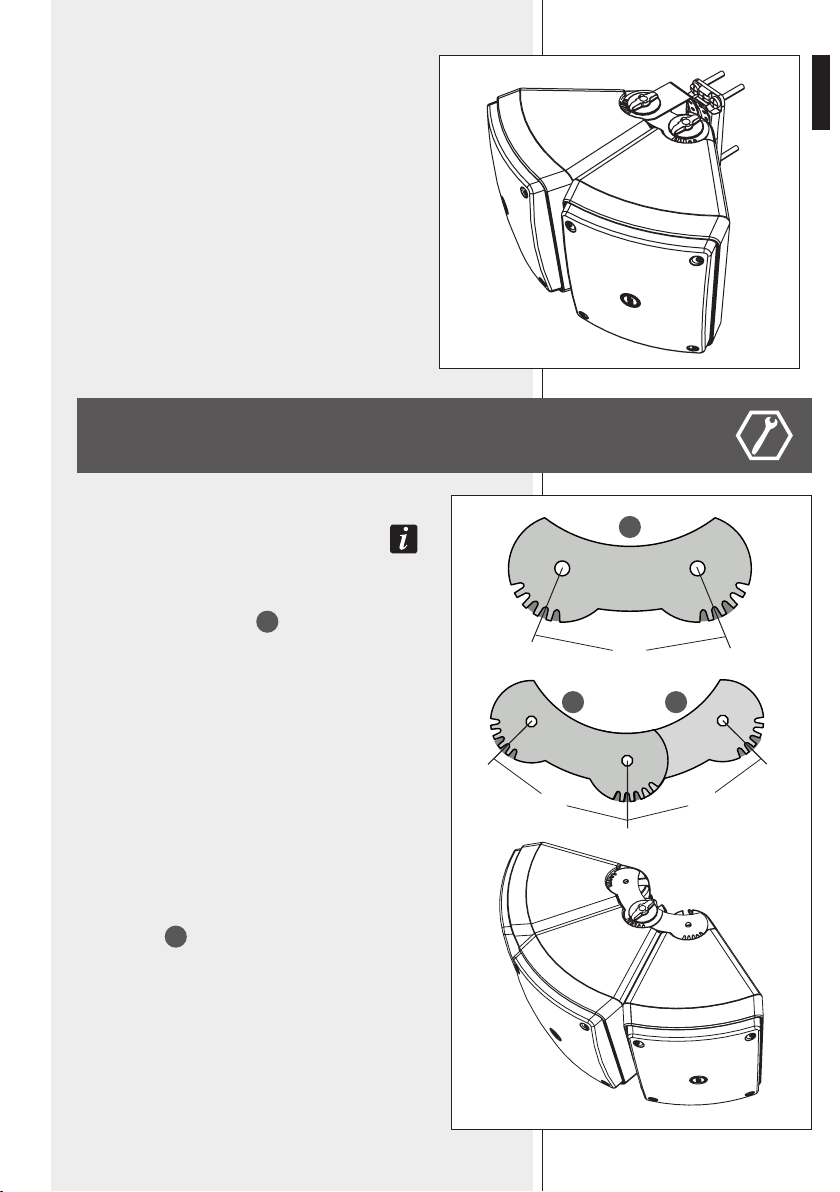
Fix the two linking supports
C
(up and down) by tightening
the two round knobs or the two bolts to the (second)
loudspeaker that will not be directly mounted on the “U”
bracket.
Always place the washers
G
and
H
as previously indicated.
45°
2nd loudspeaker
1st loudspeaker
C
9
ENGLISH
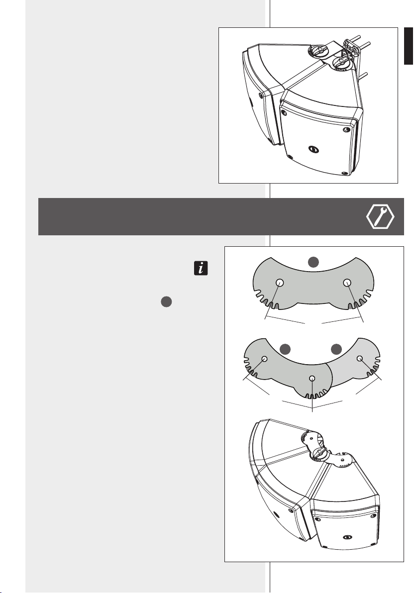
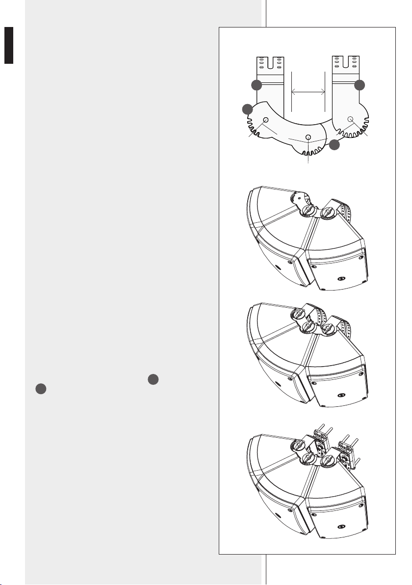
THREE LOUDSPEAKER CLUSTER
noTe: for safeTy reasons, The clusTer shall be
made horizonTally only (by puTTing TogeTher Three
loudspeakers in verTical posiTion).
It is necessary to use four linking supports
C
(two up and
two down) to make the three loudspeaker cluster.
To get the 45° angle between the two loudspeaker axes,
use the three spaces between teeth (of both sides, here
pointed out in grey) closer to the centre of the linking
support.
Put together two linking supports, in order to get a 45°
angle between the left and the central loudspeaker, a 45°
angle between the central and the right loudspeaker.
Mount the cluste to the “U” bracket by tightening other
two round knobs or bolts to fix the first loudspeaker, and
the two linking supports (with the second loudspeaker). Pay
attention to the cluster horizontal aiming.
Fix the safety steel cables (previously attached to the
mounting accesssory screws) to loudspeakers
If necessary, loosen (just a little bit) the two round knobs
/ bolts of the second loudspeaker momentarily, in order to
allow an easier insertion of the two linking supports on the
first loudspeaker (then make sure all knobs are tightened
properly).
2nd loudspeaker
1st loudspeaker
45°
45°
45°
Make the cluster by putting the three loudspeakers together
and fix the central one (and the four linking supports) by
tightening two round knobs / bolts (up and down).
C C
C

10
ENGLISH
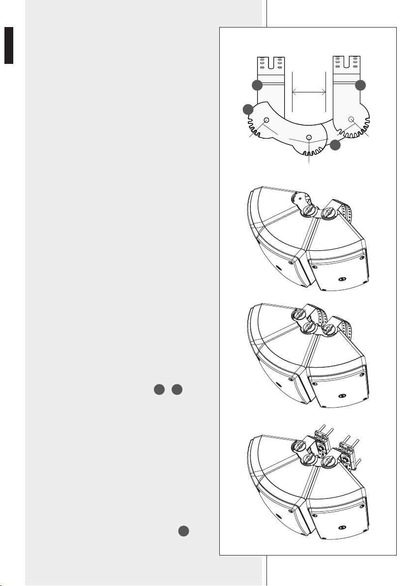
The cluster shall be wall-mounted by using two “U” brackets
(in this example: the left “U” bracket is under the linking
support, the right “U” bracket is on the linking support).
Both the “U” brackets are to be mounted parallel to the
central loudspeaker axis: pay attention to the three spaces
between teeth to be used (in this example, pointed out in
grey in the right “U” brackets).
First mount the “U” bracket (the right one in this example)
on the linking support and tighten the relevant two (up and
down) round knobs / bolts.
Then add the other “U” bracket (the left one in this example)
under the linking support and tighten the relevant two (up
and down) round knobs / bolts.
Loosen (just a little bit) the two round knobs / bolts of the
central loudspeaker momentarily, in order to allow an easier
insertion of the “U” bracket.
Then, make sure all knobs are tightened properly.
Always place the washers
G
and
H
as previously
indicated.
Now the cluster is ready to be fixed to the two wall-
mounted accessories by tightening the two bolts.
noTe: The Two mounTing accessories are To be insTalled To a wall
respecTing The fixed disTance (ca.117 mm) beTween Their axes.
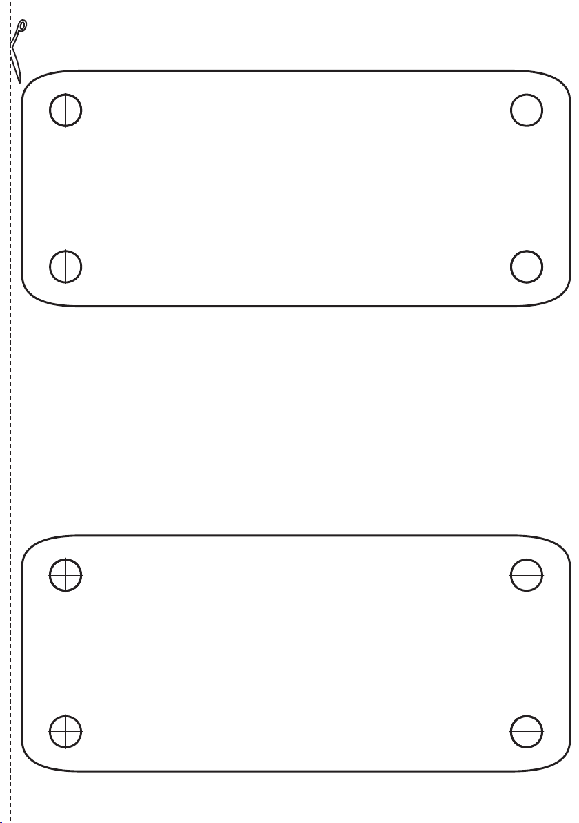
At the end of this manual, a drilling template is provided
to simplify the installation of the two mounting accessories.
Then the 3 safety steel cables (previously attached to the
mounting accessory screws) can be fixed to the loudspeakers.
Left “U” brackets
Right “U” brackets
Linking
supports
Linking
supports
parallel
45°
45°
B B
C
C

11
ENGLISH
CONNECTIONS AND PRESETTING
WARNING: loudspeaker connections should be only made by qualified and
experienced personnel having the technical know-how or sufficient specific
instructions (to ensure that connections are made correctly) in order to prevent
any electrical danger.
To prevent any risk of electric shock, do not connect loudspeakers when the
amplifier is switched on.
Before turning the system on, check all connections and make sure there are
no accidental short circuits.
The entire sound system shall be designed and installed in compliance with the
current local laws and regulations regarding electrical systems.
If the loudspeaker is installed outdoor (IP 55), all electrical connections shall be
inside weatherproof boxes / wall niches.
Connect its white wire to the line coming from the amplifier 100 V output (or
70 V); connect its black wire to line coming from the amplifier common output
(or 0, b, ––).
The internal transformer allows the connection to 100 V (/ 70 V) constant
voltage lines and the power selection (during the installation) among 30 W,
20 W, 10 W, 5 W (half power if using 70 V lines). It is possible to select the low
impedance (8 Ω) connection as well.
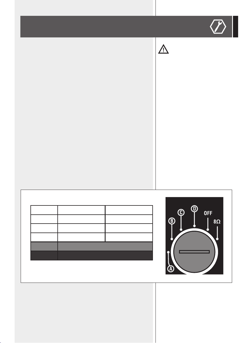
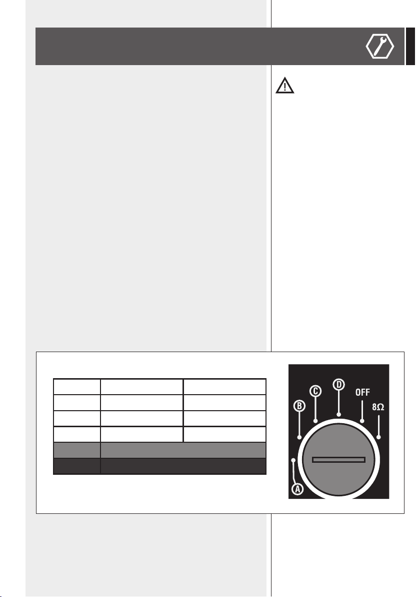
The power selection is made (by using a screw driver) through a rotary
commutator , which is normally protected by a rubber cover (that must be
removed momentarily).
Once the selector has been tapped, insert the rubber cover again.
A 5 W (100 V) 2.5 W (70 V)
B 10 W (100 V) 5 W (70 V)
C 20 W (100 V) 10 W (70 V)
D 30 W (100 V) 15 W (70 V)
OFF not connected
8 Ω Impedance: 8 Ω

12
ENGLISH
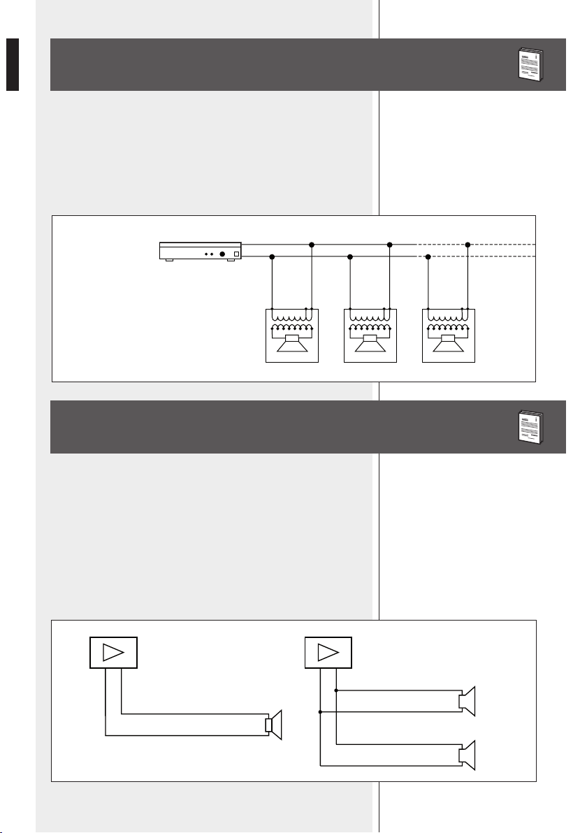
Pa = Amplifier power
Pd = Speaker power
n = Number of speakers
Vd = Speaker input voltage
Va = Amplifier output voltage
Amplifier
Pa > Pd x n Va
Vd = Va
+
–
-
+
-
+
Vd = Va
-
+
Vd = Va
NOTES ABOUT CONSTANT VOLTAGE SYSTEMS
NOTES ABOUT LOW IMPEDANCE CONNECTIONS
- The loudspeaker input voltage (Vd) must correspond to the amplifier
output voltage (Va).
- The sum of nominal power values (Pd x n) of all loudspeakers connected to
the line must not exceed the amplifier power (Pa).
- Make sure all loudspeakers are connected in phase to ensure a correct
audio reproduction.
- The total loudspeaker impedance must not be lower than the amplifier
output impedance.
noTe: a loudspeaker ToTal impedance equal To The amplifier ouTpuT one permiTs To
geT The maximum deliverable power (buT an higher loudspeaker impedance enTails
less power).
- The total loudspeaker power shall be adequate for the maximum
deliverable power of the amplifier.
- The loudspeaker line shall be short (for long distances, it may be necessary
to use cables with large cross-section wires).
white
black
Total impedance: 8 Ω
white
white
black
black
Total impedance: 4 Ω
– + – +
8 Ω
8 Ω
8 Ω
13
ENGLISH
OTHER NOTES
- Always use cables having wires with an adequate cross-section,
considering the cable length and the total loudspeaker power.
- Loudspeaker lines must be kept separated from mains cables, microphone
cables or others, in order to avoid inductive phenomena may cause hum
or noises.
- Use loudspeaker cables with twisted wires to reduce hum caused by
inductive effects due to coupling with electromagnetic fields.
- Do NOT use the 8 Ω setting when loudspeakers are connected to 100 /
70 V lines.
SPECIFICATIONS
TYPE
LOUDSPEAKERS
SENSITIVITY
MAX. SOUND PRESSURE
(MUSICAL POWER)
POWER (BYPASS)
INPUT VOLTAGE
NOMINAL IMPEDANCE
FREQUENCY RESPONSE (-10 dB)
CROSSOVER FREQUENCY
COVERAGE ANGLE:
CABINET MATERIAL
DIMENSIONS (W X H X D
COLOUR
WEIGHT
- two-way bass reflex (indoor)
- two-way sealed (outdoor, IP 55), by adding the
provided protections
- controlled directivity horn loaded 5” woofer
- controlled directivity horn loaded 1”
compression driver.
94 dB (1 W / 1 m)
114 dB
60 W (RMS) / 120 W (musical)
100 – 70.7 V
8 Ω (bypass)
333 Ω (30 W – 100 V; 15 W – 70.7 V)
500 Ω (20 W – 100 V; 10 W – 70.7 V)
1 kΩ (10 W – 100 V; 5 W – 70.7 V)
2 kΩ ( 5 W – 100 V; 2.5 W – 70.7 V)
(-10 dB) 100 Hz ÷ 20 kHz
3 kHz
90° horizontal x 60° vertical
(single horizontal installation)
high-density polystyrene
190 x 220 x 250 mm
Black / White
3 kg
14
ITALIANO
AVVERTENZE PER LA SICUREZZA
IMPORTANTE
ATTENZIONE
IMPORTANTE
Prima di collegare ed utilizzare questo prodotto, leggere attentamente
le istruzioni contenute in questo manuale, il quale è da conservare per
riferimenti futuri. Il presente manuale costituisce parte integrante del
prodotto e deve accompagnare quest’ultimo anche nei passaggi di proprietà,
per permettere al nuovo proprietario di conoscere le modalità d’installazione
e d’utilizzo e le avvertenze per la sicurezza.
L’installazione e l’utilizzo errati del prodotto esimono la RCF S.p.A. da ogni
responsabilità.
ATTENZIONE: Per prevenire i rischi di fiamme o scosse elettriche, non
esporre il diffusore alla pioggia o all’umidità ed alle polveri, salvo il caso
in cui questo sia stato espressamente progettato e costruito con un grado
di protezione IP adeguato (evidenziato nella documentazione tecnica del
dispositivo).
AVVERTENZE PER LA SICUREZZA
1. Tutte le avvertenze, in particolare quelle relative alla sicurezza,
devono essere lette con particolare attenzione, in quanto contengono
importanti informazioni.
2. La linea diffusori (uscita dell’amplificatore) può avere una tensione
sufficientemente alta (es. 100 V) da costituire un rischio di folgorazione per le
persone: non procedere mai all’installazione o alla connessione del
diffusore quando la linea diffusori è in tensione.
3. Assicurarsi che tutte le connessioni siano corrette e che la tensione
d’ingresso (in un sistema a tensione costante) oppure l’impedenza del
diffusore sia compatibile con le caratteristiche d’uscita dell’amplificatore.
4. Accertarsi che la linea diffusori non possa essere calpestata o schiacciata
da oggetti, al fine di salvaguardarne la perfetta integrità.
5. Impedire che oggetti o liquidi entrino all’interno del prodotto, perché
potrebbero causare un corto circuito.
6. Non eseguire sul prodotto interventi / modifiche / riparazioni se non quelle
espressamente descritte sul manuale istruzioni.
Contattare centri di assistenza autorizzati o personale altamente qualificato
quando:
- Il diffusore non funziona (o funziona in modo anomalo);
- il cavo è danneggiato;
- oggetti o liquidi sono entrati nel diffusore;
- il diffusore non è più integro (a causa di urti / incendio).
7. Nel caso che dal diffusore provengano odori anomali o fumo, togliere
immediatamente la tensione dalla linea diffusori e poi scollegare
il diffusore.
8. Non collegare a questo diffusore apparecchi ed accessori non previsti.

15
ITALIANO
Quando è prevista l’installazione sospesa, utilizzare solamente gli appositi
punti di ancoraggio e non cercare di appendere il diffusore con elementi non
idonei o previsti allo scopo.
Verificare inoltre l’idoneità del supporto (parete, soffitto, struttura ecc.) e
dei componenti utilizzati per il fissaggio (tasselli, viti, staffe non fornite da
RCF ecc.) che devono garantire la sicurezza dell’impianto / installazione nel
tempo, anche considerando, ad esempio, vibrazioni meccaniche normalmente
generate da un trasduttore.
9. La RCF S.p.A. raccomanda vivamente che l’installazione
di questo prodotto sia eseguita solamente da installatori
professionali qualificati (oppure da ditte specializzate) in grado
di farla correttamente e certificarla in accordo con le normative
vigenti. Tutto il sistema audio dovrà essere in conformità con le
norme e le leggi vigenti in materia di impianti elettrici.
10. Vi sono numerosi fattori meccanici ed elettrici da considerare quando si
installa un sistema audio professionale (oltre a quelli prettamente acustici,
come la pressione sonora, gli angoli di copertura, la risposta in frequenza, ecc.).
11. PERDITA DELL’UDITO
L’esposizione ad elevati livelli sonori può provocare la perdita permanente
dell’udito. Il livello di pressione acustica pericolosa per l’udito varia
sensibilmente da persona a persona e dipende dalla durata dell’esposizione.
Per evitare un’esposizione potenzialmente pericolosa ad elevati livelli di
pressione acustica, è necessario che chiunque sia sottoposto a tali livelli
utilizzi delle adeguate protezioni; quando si fa funzionare un trasduttore in
grado di produrre elevati livelli sonori è necessario indossare dei tappi per
orecchie o delle cuffie protettive.
Consultare i dati tecnici contenuti nel manuale istruzioni per conoscere la
massima pressione sonora che il diffusore acustico è in grado di produrre.
12. I diffusori devono essere collegati in fase (corrispondenza delle
polarità +/- tra amplificatori e diffusori) in modo da garantire una corretta
riproduzione audio, soprattutto quando i diffusori sono collocati in posizione
fra loro adiacente o nello stesso ambiente.
13. Per evitare che fenomeni induttivi diano luogo a ronzii, disturbi e
compromettano il buon funzionamento dell’impianto, le linee diffusori
non devono essere canalizzate insieme ai conduttori dell’energia elettrica,
ai cavi microfonici, alle linee di segnale a basso livello che fanno capo ad
amplificatori.
14. Il cavo per il collegamento del diffusore dovrà avere conduttori di sezione
adeguata (possibilmente intrecciati, per minimizzare gli effetti induttivi dovuti
all’accoppiamento con campi elettro-magnetici circostanti) ed un isolamento
idoneo.
PRECAUZIONI D’USO
- Collocare il diffusore lontano da fonti di calore.
- Non forzare mai gli organi di comando (tasti, manopole ecc.).
- Non usare solventi, alcool, benzina o altre sostanze volatili per la pulitura
delle parti esterne.
- Se il diffusore viene utilizzato in ambienti particolarmente freddi, pilotarlo
con un segnale a basso livello per 5-10 minuti, prima di utilizzarlo alla
massima potenza.
PRECAUZIONI D’USO

16
ITALIANO
DESCRIZIONE
RCF S.P.A. VI RINGRAZIA PER L’ACQUISTO DI QUESTO PRODOTTO,
REALIZZATO IN MODO DA GARANTIRNE L’AFFIDABILITÀ E
PRESTAZIONI ELEVATE.
MQ 80P è un diffusore a due vie (con caricamento a tromba) che fa parte
della serie MONITOR Q. La sua qualità, l’alta efficienza e le dimensioni
compatte ne fanno la soluzione ideale per ottenere una buona fedeltà della
voce e della musica in ambienti di medie dimensioni; è adatto sia per la
diffusione di annunci sia per la riproduzione della musica di sottofondo.
Grazie alla sua direttività di 90°x 60°, il diffusore MQ 80P può essere
combinato in un “cluster” (gruppo di diffusori installati insieme nello stesso
punto e disposti a grappolo / ventaglio) di due o tre pezzi, in modo da
ottenere una copertura ampia ed uniforme e ridurre i punti d’installazione.
Può essere installato sia in ambienti chiusi sia (dopo aver chiuso le “porte
reflex” ) all’aperto (con grado di protezione: IP 55). Il woofer è ad alta
escursione con cono rivestito in resina epossidica ed il bordo in gomma,
montato in una cassa di tipo “bass reflex”, la quale può essere convertita
in una cassa chiusa e stagna (chiudendo le due porte reflex) per l’uso
all’aperto. Il tweeter è un driver a compressione caricato a tromba con
rifasatore. L’installazione è rapida grazie alla staffa originale con diversi punti
di fissaggio corrispondenti ad angolazioni diverse; il collegamento elettrico si
effettua tramite un cavo bipolare. La selezione della potenza (e della modalità
ad impedenza costante 8 ohm) si effettua tramite un commutatore rotativo
(posto sotto un tappo di protezione). Il mobile è costruito in polistirene ad
alta densità, resistente ai raggi UV e corredato di una griglia d’acciaio inox.
MQ 80P è disponibile in tre colori: bianco (MQ 80P-W); nero (MQ 80P-B).
L’installazione dei diffusori deve essere effettuata
da personale qualificato, rispettando gli standard di
sicurezza. Eseguire un’installazione sicura di ogni
diffusore, controllando che la struttura di supporto
(es. parete, soffitto, ecc.) abbia le necessarie
caratteristiche meccaniche, tali da consentirgli di
sopportarne il peso senza il pericolo di cadute che
potrebbero compromettere l’incolumità di cose
o persone. Fissare i cavi di sicurezza in acciaio ai
diffusori. Utilizzare elementi di fissaggio adatti al tipo
di struttura che deve sostenere i diffusori (es. tasselli
per mattoni forati, tasselli per calcestruzzo, ecc.).
NOTE SULL’INSTALLAZIONE
17
ITALIANO
NELL’IMBALLO
-
A
diffusore MQ 80P
-
B
staffa ad “U”
-
C
staffa di collegamento (x 2)
-
D
accessorio per il montaggio
(con bullone) della staffa a “U”+
-
E
fermo
-
F
bulloni (x3)
-
G
rondelle elastiche (x3)
-
H
rondelle piane (x3)
-
L
manopole con bullone (x 2)
-
M
cavo di sicurezza in acciaio
-
N
tappo per porta reflex (x 2)
-
P
viti (x5)
la dima di foraTura è in quesTo manuale.
18
ITALIANO
INTERNO / ESTERNO
INSTALLAZIONE DI UN SINGOLO DIFFUSORE
Il diffusore MQ 80P è normalmente di tipo bass-reflex e
predisposto per il solo uso interno; tuttavia, può inoltre
essere usato all’esterno o in ambienti molto umidi (con
grado di protezione IP 55) se adattato come “cassa
chiusa”:
- Rimuovere la griglia di protezione
S
svitando le
quattro viti;
- Coprire le due porte reflex (i fori) usando i due tappi
con guarnizione in gomma
N
, ciascuno dei quali va
fissato con due viti autofilettanti
P
;
- Rimontare la griglia
S
.
Un diffusore singolo può essere installato a
parete sia orizzontalmente (angolo di copertura:
90° orizz. x 60° vert.) oppure verticalmente
(60° orizz. x 90° vert.).
Installare a muro l’accessorio per il montaggio
D
tramite quattro viti M8 (non incluse,
in quanto devono essere scelte in base alla
superficie di fissaggio).
Ad una delle viti, fissare il cavo di sicurezza in
acciaio
M
.
Se il diffusore è installato verticalmente,
l’accessorio per il montaggio
D
può essere
fissato ad un palo tramite due fascette d’acciaio
inox larghe 13 mm .
x4
S
N
P
D
D
M
19
ITALIANO
Il cavo del diffusore (lunghezza: 1 m) può passare
attraverso la staffa a “U”, un foro (apribile facendo
pressione su uno dei due punti indicati qui a lato) e
la sede posteriore dell’accessorio di montaggio, per
raggiungere una nicchia / scatola eventualmente
a tenuta stagna incassata nel muro, in modo da
ottenere una connessione elettrica ben protetta
dall’acqua e ridurre la parte esterna visibile del cavo.
Mettere la staffa ad “U”
B
sull’accessorio
per il montaggio
D
e scegliere l’inclinazione
verticale* più adatta (± 30°; ogni foro
corrisponde ad un incremento di 7.5°), poi
fissarla posizionando il fermo in plastica
E
e stringendo il bullone
F
interponendo le
rondelle
G
e
H
come in figura.
La staffa a “U” consente un’inclinazione
orizzontale* di 30° verso destra / 75° verso
sinistra
a
oppure 75° verso destra / 30° verso
sinistra
b
, secondo com’è installata. Ogni
dente, da incastrare con il riferimento sul diffusore,
corrisponde ad una inclinazione di circa 15°.
* noTa: supponendo che il diffusore sia insTallaTo
verTicalmenTe.
Use a screw
P
to fix the safety steel cable
M
as shown in this example.
E
G
D
H
F
a b
B
P
M
20
ITALIANO
Posizionare il diffusore nella staffa a “U”, puntarlo nella giusta direzione e
fissarlo stringendo le due manopole
L
oppure i due bulloni
F
(sopra e
sotto), avendo cura di interporre le rondelle
G
e
H
.
L’utilizzo dei bulloni
F
è raccomandabile nelle installazioni all’aperto.
“CLUSTER” CON DUE DIFFUSORI
noTa: per moTivi di sicurezza, il clusTer è realizzabile
solo orizzonTalmenTe (unendo due diffusori posTi in
posizione verTicale).
Installare l’accessorio di montaggio e la staffa a “U” (vedere il
paragrafo precedente “Installazione di un singolo diffusore”).
Per la realizzazione del cluster, devono essere utilizzate due
staffe di collegamento (sopra e sotto).
Per fissare i due diffusori mantenendo l’angolo ottimale di
45° tra i loro due assi (in modo da ottenere una copertura
uniforme), usare i tre spazi tra i denti più vicini al centro (qui
evidenziati in grigio su entrambi i lati).
Fissare le due staffe di collegamento
C
(sopra e sotto) al
secondo diffusore (quello che non sarà direttamente fissato
alla staffa a “U”) stringendo le due manopole con bullone
L
(oppure i due bulloni
F
). Interporre sempre le due rondelle
G
e
H
rispettivamente elastica e piana, come descritto
precedentemente.
45°
2° diffusore
1° diffusore
C
21
ITALIANO
“CLUSTER” CON TRE DIFFUSORI
noTa: per moTivi di sicurezza, il clusTer è realizzabile
solo orizzonTalmenTe (unendo Tre diffusori posTi in
posizione verTicale)
Per la realizzazione del cluster, devono essere utilizzate
quattro staffe di collegamento
C
(due sopra e due sotto).
Per ottenere l’angolo di 45° tra gli assi di due diffusori,
usare i tre spazi tra i denti più vicini al centro della staffa
(qui evidenziati in grigio su entrambi i lati).
Unire due staffe di collegamento in modo da avere un
angolo di 45° tra il diffusore sinistro e quello centrale, e
45° tra il diffusore centrale e quello destro.
Montare il cluster ottenuto alla staffa a “U” stringendo
altre due manopole per fissare il primo diffusore, attaccando
il cavo di sicurezza in acciaio (già fissato all’accessorio di
montaggio a parete) e le due staffe di collegamento (con
il secondo diffusore). Prestare attenzione all’orientamento
del cluster.
Se necessario, allentare appena (momentaneamente) le due
manopole del secondo diffusore, in modo da rendere più
semplice l’inserzione delle due staffe di collegamento sul
primo diffusore (poi serrare tutte le manopole o i bulloni).
2° diffusore
1° diffusore
45°
45°
45°
Formare il cluster unendo i tre diffusori e fissare quello
centrale (e le quattro staffe di collegamento) stringendo
due manopole
L
con bullone (sopra e sotto).
C C
C
22
ITALIANO
Il cluster deve essere installato a parete tramite due staffe
a “U” (nell’esempio a lato: la staffa a “U” sinistra è sotto a
quella di collegamento; la staffa a “U” destra è sopra quella
di collegamento). Il disegno a lato mostra la disposizione
superiore delle staffe; la stessa disposizione è da rispettare
per il fissaggio inferiore delle staffe medesime.
Entrambe le staffe a “U” devono essere montate parallele
all’asse del diffusore centrale: prestare attenzione ai tre spazi
tra denti che devono essere usati (nell’esempio, evidenziati
in grigio sulla staffa a “U” destra).
Montare la prima staffa a “U” (quella a destra nell’esempio
qui raffigurato) sulla staffa di collegamento e stringere le
relative due manopole o i bulloni (sopra e sotto).
Aggiungere successivamente l’atra staffa a “U” (nell’esempio,
quella a sinistra) sotto la staffa di collegamento e stringere le
altre due manopole.
Allentare appena momentaneamente le due manopole
poste sul diffusore centrale per permettere l’inserimento
della staffa a “U”, poi accertarsi che tutte le manopole siano
ben serrate. Interporre sempre le rondelle
G
e
H
come al
precedente paragrafo.
Il cluster si può ora fissare ai due accessori di montaggio (già
installati a parete) stringendo i relativi bulloni.
Nota: i due accessori di montaggio devono essere installati
ad una parete rispettando la distanza fissa (ca.117 mm) tra
i loro assi.
Alla fine del manuale, è fornita una dima di foratura per
facilitare il posizionamento e l’installazione dei due accessori
di montaggio.
I 3 cavi di sicurezza in acciaio (precedentemente fissati alle
viti degli accessori di montaggio) possono ora essere fissati
ai diffusori posteriormente tramite le apposite viti
P
.
Staffa ad “U” sinistra
Staffa ad “U” destra
Staffa di
collegamento
Staffa di
collegamento
parallele
45°
45°
B B
C
C
23
ITALIANO
COLLEGAMENTO ED IMPOSTAZIONE
ATTENZIONE: per il collegamento del diffusore si raccomanda di rivolgersi
a personale qualificato ed addestrato, ossia personale avente conoscenze
tecniche o esperienza o istruzioni specifiche sufficienti per permettergli di
realizzare correttamente le connessioni e prevenire i pericoli dell’elettricità.
Per evitare il rischio di shock elettrici, non collegare il diffusore con
l’amplificatore acceso. Prima di far funzionare il diffusore, è buona norma
ricontrollare tutte le connessioni, verificando attentamente che non vi siano
dei cortocircuiti accidentali. Tutto l’impianto di sonorizzazione dovrà essere
realizzato in conformità con le norme e le leggi vigenti in materia di impianti
elettrici. Se il diffusore è installato all’aperto (dove si richiede la protezione IP
55), le connessioni elettriche devo essere poste all’interno di una scatola di
protezione a tenuta stagna (oppure una nicchia incassata a parete).
Collegare il filo bianco alla linea proveniente dall’uscita 100 V o (70V)
dell’amplificatore; collegare il filo nero alla linea proveniente dall’uscita COM o
(0) dell’amplificatore. Il trasformatore interno permette il collegamento a linee
con tensione costante 100 V o (70 V) e la selezione della potenza (durante
l’installazione) tra 30 W, 20 W, 10 W, 5 W (metà potenza utilizzando linee a 70
V). E’ inoltre possibile selezionare la connessione a bassa impedenza (8 Ω).
La selezione della potenza è effettuata ruotando un commutatore sul pannello
posteriore (normalmente protetto da un tappo di gomma rimovibile) tramite
un cacciavite.
Una volta effettuata la selezione della potenza riposizionare accuratamente
il tappo.
A 5 W (100 V) 2,5 W (70 V)
B 10 W (100 V) 5 W (70 V)
C 20 W (100 V) 10 W (70 V)
D 30 W (100 V) 15 W (70 V)
OFF non connesso
8 Ω Impedenza: 8 Ω

24
ITALIANO
Pa = Potenza amplificatore
Pd = Potenza diffusore
n = Numero diffusori
Vd = Tensione ingresso diffusore
Va = Tensione uscita amplificatore
Amplificatore
Pa > Pd x n Va
Vd = Va
+
–
-
+
-
+
Vd = Va
-
+
Vd = Va
NOTE SUI SISTEMI A TENSIONE COSTANTE
NOTE SUI SISTEMI CON CONNESSIONE
A BASSA IMPEDENZA
- La tensione d’ingresso del diffusore (Vd) deve corrispondere con la
tensione d’uscita dell’amplificatore (Va).
- La somma delle potenze nominali di tutti i diffusori (Pd x n) collegati alla
linea non deve superare quella dell’amplificatore (Pa).
- Per garantire una corretta riproduzione audio, effettuare il collegamento di
tutti i diffusori “in fase”.
- L’impedenza totale dei diffusori non deve essere inferiore a quella d’uscita
dell’amplificatore;
noTa: l’impedenza complessiva dei diffusori uguale a quella d’usciTa
dell’amplificaTore permeTTe l’erogazione della massima poTenza (menTre
un’impedenza superiore comporTa una riduzione della poTenza erogaTa).
- La somma delle potenze dei diffusori deve essere adeguata alla potenza
massima erogabile dall’amplificatore.
- La lunghezza delle linee diffusori deve essere ridotta al minimo (una lunga
distanza può comportare l’uso di cavi con sezioni elevate).
bianco
nero
Impedenza complessiva: 8 Ω
nero
bianco
nero
nero
Impedenza complessiva: 4 Ω
– + – +
8 Ω
8 Ω
8 Ω

25
ITALIANO
ALTRE NOTE
- Utilizzare dei cavi con conduttori aventi una sezione adeguata,
considerando la loro lunghezza e la potenza complessiva dei diffusori.
- Per evitare che fenomeni induttivi diano luogo a ronzii, disturbi e
compromettano il funzionamento del sistema, i cavi per i diffusori non
devono essere canalizzati assieme ai conduttori dell’energia elettrica, ai
cavi microfonici od altre linee.
- Per minimizzare gli effetti induttivi (ronzii) dovuti all’accoppiamento con
campi elettromagnetici circostanti, utilizzare cavi con conduttori intrecciati.
- NON impostare nessun commutatore sulla posizione “8 Ω” quando i
diffusori sono collegati a linee 100 / 70 V.
DATI TECNICI
TIPO
ALTOPARLANTI
SENSIBILITÀ
MAX. PRESSIONE SONORA
(POTENZA MUSICALE)
POTENZA (BYPASS)
TENSIONE D’INGRESSO
IMPEDENZA NOMINALE
RISPOSTA IN FREQUENZA (-10 dB)
FREQUENZA DI CROSSOVER
ANGOLO DI COPERTURA:
CORPO
GRIGLIA FRONTALE
ACCESSORI DI MONTAGGIO
DIMENSIONI (l x h x p)
COLORE
PESO
- due vie bass reflex (per interno)
- due vie “cassa chiusa” (per esterno, IP 55), adattando
il diffusore con le protezioni in dotazione
- woofer 5” caricato a tromba (direttività controllata)
- driver 1” caricato a tromba (direttività controllata)
94 dB (1 W / 1 m)
114 dB SPL
60 W (RMS) / 120 W (musicale)
100 – 70,7 V
8 Ω (bypass)
333 Ω (30 W – 100 V; 15 W – 70,7 V)
500 Ω (20 W – 100 V; 10 W – 70,7 V)
1 kΩ (10 W – 100 V; 5 W – 70,7 V)
2 kΩ ( 5 W – 100 V; 2.5 W – 70,7 V)
100 Hz ÷ 20 kHz
3 kHz
90° orizzontale x 60° verticale
(diffusore singolo installato orizzontalmente)
Polistirene ad alta densità
Acciaio Inox
Acciaio Inox
190 x 220 x 250 mm
Nero / Bianco
3 kg

26
DEUTSCH
SICHERHEITSHINWEISE
WICHTIGE HINWEISE
ACHTUNG
WICHTIGE HINWEISE:
Bevor Sie dieses Gerät in Betrieb nehmen, lesen Sie die Bedienungsanleitung
bitte sorgfältig durch und halten Sie diese zur weiteren Einsichtnahme
bereit. Die Bedienungsanleitung sollte als wesentlicher Bestandteil dieses
Produkts verstanden werden und sollte diesem auch dann beiliegen,
wenn das Gerät den Besitzer wechselt, um eine korrekte Installation und
Benutzung zu gewährleisten sowie um als Referenz für alle notwendigen
Sicherheitsvorkehrungen zu dienen. Eine unsachgemäße Installation und/
oder Benutzung dieses Produkts befreit RCF S.p.A. von jeglicher Haftung.
ACHTUNG: Um die Gefahr eines Brandes oder eines Stromschlags
auszuschließen, setzen Sie den Lautsprecher niemals Regen, Feuchtigkeit oder
Staub aus, es sei denn, dieser wurde ausdrücklich für diesen Einsatzzweck
entwickelt und gefertigt und weist den entsprechenden IP-Schutzgrad auf
(dieser ist den Produktspezifikationen zu entnehmen).
SICHERHEITSHINWEISE
1. Alle Anweisungen, im Besonderen die sicherheitsrelevanten, müssen
mit besonderer Aufmerksamkeit gelesen werden, da sie entscheidende
Informationen enthalten.
2. An Lautsprecherleitungen (bzw. Verstärkerausgängen) liegt eine
ausreichend hohe Spannung an (100 V), um einen tödlichen Stromschlag
zu verursachen. Schließen Sie den Lautsprecher niemals an oder
installieren Sie diesen, wenn Spannung an seiner Leitung anliegt.
3. Stellen Sie vor dem Einschalten sicher, dass alle Anschlüsse korrekt
vorgenommen wurden und dass die Eingangsspannung des Lautsprechers
(bei Systemen mit Konstantspannung) oder seine Impedanz auf die des
anliegenden Verstärkerausgangs abgestimmt ist.
4. Schützen Sie das Lautsprecherkabel vor Beschädigungen. Stellen Sie sicher,
dass dieses so positioniert wird, dass nicht darauf getreten oder es von
Gegenständen eingedrückt werden kann.
5. Stellen Sie sicher, dass keine Gegenstände oder Flüssigkeiten ins Innere
des Geräts gelangen können, da dies zu einem Kurzschluss führen kann.
6. Versuchen Sie niemals das Gerät auf eine Weise einzusetzen oder
Modifikationen und Reparaturen an diesem durchzuführen, die nicht
ausdrücklich in dieser Bedienungsanleitung beschrieben werden.
Kontaktieren Sie Ihr autorisiertes Service-Center oder qualifiziertes
Fachpersonal, sollte eines der folgenden Ereignisse auftreten:
- Das Gerät funktioniert nicht (oder funktioniert nicht korrekt).
- Das Kabel wurde beschädigt.
- Gegenstände oder Flüssigkeiten sind ins Innere des Geräts gelangt.
- Der Lautsprecher wurde durch einen heftigen Stoß oder einen Brand
beschädigt.
7. Sollte von dem Lautsprecher ein ungewohnter Geruch oder Rauch
ausgehen, schalten Sie diesen unverzüglich aus und trennen Sie das
Anschlusskabel.

27
DEUTSCH
8. Verbinden Sie das Produkt nur mit dafür vorgesehenen Geräten und
Zubehörteilen.
Nutzen Sie für eine hängende Installation ausschließlich die vorgesehenen
Verankerungspunkte und versuchen Sie nicht, das Produkt mit für
diesen Zweck ungeeigneten Montageelementen zu befestigen. Prüfen
Sie zudem die Eignung der Stützfläche (Wand, Decke, Struktur etc.)
und des Befestigungsmaterials (Dübel, Schrauben, Winkel etc., nicht im
Lieferprogramm von RCF), um eine langfristige Sicherheit des Systems sowie
seiner Installation zu gewährleisten. Berücksichtigen Sie dabei beispielsweise
auch die mechanischen Vibrationen, die gewöhnlich von einem akustischen
Wandler ausgehen.
9. RCF S.p.A. empfiehlt nachdrücklich, die Installation dieses Geräts
ausschließlich von qualifiziertem Fachpersonal (oder spezialisierten
Firmen) durchführen zu lassen, die eine korrekte Installation
sicherstellen und diese gemäß der geltenden Bestimmungen
zertifizieren können.
Das gesamte Beschallungssystem muss den geltenden Standards
und Vorschriften für elektrische Anlagen entsprechen.
10. Bei der Installation einer professionellen Beschallungsanlage
müssen neben rein akustischen Parametern (wie etwa Schalldruck,
Abdeckungswinkel, Frequenzgang etc.) einige mechanische und elektrische
Faktoren beachtet werden.
11. GEHÖRSCHÄDIGUNG
Die Einwirkung hoher Lautstärkepegel kann zu dauerhaften
Gehörschädigungen führen. Der Schalldruckpegel, der zu einer Schädigung
des Gehörs führt, unterscheidet sich von Person zu Person und ist von der
Dauer der Einwirkung abhängig. Um potentielle Gefahren durch hohe
Schalldruckpegel zu vermeiden, sollte jeder, der diesen Pegeln ausgesetzt
ist, einen geeigneten Gehörschutz verwenden. Beim Einsatz eines
leistungsfähigen Schallerzeugers, der hohe Lautstärkepegel erzeugt, ist es
erforderlich Gehörschutzstöpsel oder Ohrenschützer zu tragen.
12. Um eine korrekte Musikwiedergabe zu gewährleisten, ist die Phasenlage
der Lautsprecher zu berücksichtigen (so auch die Polarität der Verstärker
beim Anschluss der Lautsprecher). Dies ist entscheidend, wenn Lautsprecher
nebeneinander aufgestellt werden, zum Beispiel innerhalb eines Raums.
13. Um das Auftreten von Induktionseffekten, wie Brummen, oder
Störgeräusche und Fehlfunktionen zu vermeiden, platzieren Sie die
Lautsprecherkabel nicht in der Nähe von Netzstromkabeln oder
Lautsprecherleitungen.
14. Die Leiter des Lautsprecherkabels müssen einen angemessenen
Querschnitt (wenn möglich verdrillte Drähte zur Minimierung induktiver
Effekte, die von umliegenden elektromagnetischen Feldern erzeugt werden)
sowie eine ausreichende elektrische Isolierung aufweisen.
SICHERHEITSMASSNAHMEN FÜR DEN BETRIEB
- Installieren Sie den Lautsprecher nicht in der Nähe von Wärmequellen.
- Überlasten Sie das Gerät nicht über einen längeren Zeitraum.
- Forcieren Sie nicht die Bedienelemente (Tasten, Kontrollvorrichtungen, usw.).
- Vermeiden Sie bei der Reinigung der Außenteile den Gebrauch von
Lösungsmitteln, Alkohol, Benzin oder anderen flüchtigen Substanzen.
- Bei Verwendung des Lautsprechers in einer ausgesprochen kühlen Umgebung:
Betreiben Sie diesen für 5 - 10 Minuten mit einem geringen Ausgangspegel,
bevor Sie den Lautsprecher mit maximaler Leistung nutzen.
SICHERHEITSMASSNAHMEN
FÜR DEN BETRIEB
28
DEUTSCH
BESCHREIBUNG
R.C.F S.P.A. DANKT IHNEN FÜR DEN KAUF DIESES PRODUKTS,
DAS AUF HÖCHSTE ZUVERLÄSSIGKEIT UND LEISTUNGSFÄHIGKEIT
AUSGELEGT IST.
Die Lautsprecher müssen von fachkundigem Personal
unter Berücksichtigung aller Sicherheitsstandards
installiert werden. Dabei ist eine sichere Befestigung
zu gewährleisten. Es wird dringend empfohlen zu
prüfen, ob die Montagefläche (Gipskartonplatten
/ Holzpaneele) über die nötigen mechanischen
Eigenschaften verfügt, um das Gewicht des
Lautsprechers zu tragen. So kann das Herunterfallen
des Lautsprechers verhindert und Verletzungen oder
Sachschäden ausgeschlossen werden. Sichern Sie die
Lautsprecher mit Sicherheitsfangseilen (aus Stahl).
Verwenden Sie für die jeweiligen Wände / Decken
geeignete Befestigungsmaterialen (z.B. Dübel für
Mauerwerk, Betondübel etc.)
INSTALLATIONSHINWEISE
Der MQ 80P ist ein horngeladenes 2-Wege-Lautsprechersystem der Monitor Q-Serie.
Seine hohe Qualität, hohe Effizienz und kompakte Bauweise machen es zur idealen
Lösung für eine detailgetreue Sprach- und Musikwiedergabe in mittelgroßen
Beschallungsumgebungen. Es eignet sich gleichermaßen für Sprachdurchsagen und
Hintergrundmusik.
Dank seiner Richtwirkung von 90° x 60°, kann der MQ 80P in Clustern von zwei
oder drei Lautsprechern kombiniert werden, um eine breite und gleichmäßige
Abdeckung zu erzielen und dabei die Anzahl von Installationspunkten zu
reduzieren.
Es eignet sich sowohl für Innen- als auch (nach Abdichten der Reflexports) für
Außenanwendungen (IP 55). Der Tieftöner (Woofer) im High-Excursion-Design
verfügt über eine mit Epoxidharz beschichtete Papiermembran mit Gummisicke und
ist in einem speziell abgestimmten Gehäuse untergebracht. (Die Ports können zur
Aufstellung im Freien dicht verschlossen werden.)
Der Hochtöner (Tweeter) ist ein horngeladener Kompressionstreiber mit Phase-Plug.
Die einzigartige Halterung des Lautsprechers ermöglicht mit ihren variablen
Befestigungspunkten und Ausrichtungsmöglichkeiten eine schnelle und einfache
Installation. Die elektrischen Anschlüsse werden mittels eines zweiadrigen Kabels
durchgeführt.
Die Ausgangsleistung (sowie der 8-Ohm-Betrieb) können mithilfe eines
Drehschalters ausgewählt werden, der unter einer dichten Abdeckung
untergebracht ist.
Das Gehäuse besteht aus hochverdichtetem, UV-beständigem Polystyrol und verfügt
über ein Edelstahl-Frontgitter. Das MQ 80P ist in zwei Farben erhältlich:
Weiß (MQ 80P-W), Schwarz (MQ 80P-B).

29
DEUTSCH
INNEN-/ AUSSENANWENDUNG
-
A
Lautsprecher MQ 80P
-
B
U-Bügel
-
C
Verbindungsplatte (2 x)
-
D
Komplettes Befestigungszubehör
(inkl. Bolzen) für den U-Bügel +
-
E
Kunststoffplatte
-
F
Bolzen (3x)
-
G
Federring (3x)
-
H
Unterlegscheibe (3x)
-
L
Rändelknopf (3x)
-
M
Sicherheitsfangseil
-
N
Abdeckung für Reflex-Ports (2x)
-
P
Schrauben (5x)
eine bohrschablone befindeT sich am ende dieser
bedienungsanleiTung.
30
DEUTSCH
INNEN-/ AUSSENANWENDUNG
INSTALLATION EINES EINZELNEN LAUTSPRECHERS
Standardmäßig ist der MQ 80P Bassreflex-Lautsprecher
für Anwendungen im Innenbereich ausgelegt. Er kann
jedoch auch im Freien oder in feuchten Umgebungen
verwendet werden (gem. Schutzart: IP 55), wenn der
Lautsprecher als geschlossene Box angepasst wird:
- Nehmen Sie das Lautsprechergitter
S
ab, indem Sie
die vier Schrauben entfernen.
- Verschließen Sie die zwei Reflex-Ports mithilfe der beiden
mit Gummi abgedichteten Stöpsel
N
und fixieren Sie
diese mit jeweils zwei Gewindeschneideschrauben
P
- Bringen Sie dann das Lautsprechergitter wieder an.
Ein einzelner Lautsprecher kann entweder
horizontal (Abstrahlwinkel: 90° horizontal x
60° vertikal) oder vertikal (Abstrahlwinkel: 60°
horizontal x 90° vertikal) ausgerichtet an einer
Wand installiert werden.
Befestigen Sie zuerst das Montagezubehör
D
mit vier M8-Schrauben an der Wand (nicht im
Lieferumfang enthalten; passende Schrauben
sind abhängig von der Wandbeschaffenheit zu
wählen).
Befestigen Sie das Sicherheitsstahlseil
M
mithilfe der Befestigungsschraube am Monta-
gezubehör.
Wird der Lautsprecher vertikal installiert, kann
das Montagezubehör
D
auch an einer
x4
S
N
P
D
D
M
31
DEUTSCH
Stange befestigt werden. Verwenden Sie hierzu zwei
Edelstahlbänder (je eines oben und unten) mit einer
Breite von 13 mm (oder ½“ ≈ 12,7 mm).
Das Lautsprecherkabel (Länge: 1 m) kann durch
den U-Bügel und eine Öffnung im Montagezubehör
(durch Eindrücken einer der beiden Punkte, siehe
Abbildung) geführt werden um möglichst direkt
in der Wandnische / dem (wetterfesten) Unter-
putzeinbaukasten hinter der Wandhalterung zu
verlaufen. So kann der sichtbare Teil des Kabels re-
duziert und eine wetterfeste elektrische Verbindung
gewährleistet werden.
Bringen Sie den U-Bügel
B
am
Montagezubehör
D
an und wählen Sie einen
geeigneten horizontalen Ausrichtungswinkel
(± 30°; jedes Loch entspricht einem 7,5°
Schritt). Fixieren Sie die Halterung dann durch
Festziehen des Bolzens
F
, den Sie durch die
Kunststoffplatte
E
die Unterlegscheibe
H
und
den Federring
G
führen.
Der U-Bügel ermöglicht (im Falle einer vertikalen
Montage) eine horizontale Ausrichtung des
Lautsprechers von 30° nach rechts / 75° nach
links (Abbildung
a
) oder von 75° nach rechts
/ 30° nach links (Abbildung
b
), abhängig von
der Orientierung der Halterung. Jeder Schritt
entspricht etwa 15°.
Verwenden Sie eine Schraube
P
, um das Sicherungsfangseil
M
zu befesti-
gen (wie in der Abbildung dargestellt).
E
G
D
H
F
a b
B
P
M
32
DEUTSCH
Setzen Sie den Lautsprecher in die Halterung ein, richten Sie diesen aus und
fixieren Sie ihn (oben und unten) mit den beiden Rändelknöpfen
L
oder mit
zwei Bolzen
F
, jeweils mit Unterlegscheibe
H
und Federring
G
.
Bei Installationen in Innenräumen wird dringend die Verwendung der Bolzen
F
empfohlen.
2ER-LAUTSPRECHER-CLUSTER
hinweis: aus sicherheiTsgründen sollTe das clusTer ausschliesslich
horizonTal angeordneT werden (durch zusammensTellen von zwei
verTikal ausgerichTeTen lauTsprechern).
Installieren Sie das Montagezubehör und den Bügel wie
im vorangehenden Kapitel („Installation eines einzelnen
Lautsprechers“) beschrieben.
Zur Bildung des Clusters sind zwei Verbindungsplatten
C
(je
eine oben und unten) erforderlich.
Um einen optimalen Winkel von 45° zwischen den
Hauptabstrahlachsen der beiden Lautsprecher (und so eine
gleichmäßige Abdeckung) zu erzielen, nutzen Sie die drei
Zwischenräume der Zahnung der Verbindungsplatte (in der
Abbildung grau unterlegt).
Fixieren Sie die beiden Verbindungsplatten
C
(oben
und unten) durch Festziehen der Rändelknöpfe
L
oder
Bolzen
F
, zunächst am zweiten Lautsprecher, der nicht
direkt am U-Bügel anliegt.
Verwenden Sie stets Unterlegscheibe
H
und Federring
G
,
wie zuvor beschrieben.
45°
2. Lautsprecher
1. Lautsprecher
C
33
DEUTSCH
3ER-LAUTSPRECHER-CLUSTER
hinweis: aus sicherheiTsgründen sollTe das clusTer
ausschliesslich horizonTal angeordneT werden (durch
zusammensTellen von drei verTikal ausgerichTeTen lauTsprechern).
Zur Bildung des Clusters mit drei Lautsprechern sind
vier Verbindungsplatten
C
(je zwei oben und unten)
erforderlich.
Um einen optimalen Winkel von 45° zwischen den
Hauptabstrahlachsen zweier Lautsprecher zu erzielen,
nutzen Sie die drei inneren Zwischenräume der Zahnung
der Verbindungsplatte (in der Abbildung grau unterlegt).
Setzen Sie zwei Verbindungsplatten zusammen, um einen
Winkel von 45° zwischen dem linken und dem mittleren
Lautsprecher sowie einen Winkel von 45° zwischen dem
mittleren und rechten Lautsprecher zu erzielen.
Fügen Sie die drei Lautsprecher zusammen und fixieren
Sie den mittleren (und die vier Verbindungsplatten) durch
Festziehen der beiden mittleren Rändelknöpfe oder Bolzen
(oben und unten).
Das Cluster muss mit zwei U-Bügeln an der Wand befestigt
werden. (In der beispielhaften Abbildung befindet sich
der linke U-Bügel unter der Verbindungsplatte, die rechte
darüber.)
Befestigen Sie das Lautsprecher-Cluster am U-Bügel durch
Festziehen der beiden übrigen Rändelknöpfe
L
oder
Bolzen
F
am direkt anliegenden Lautsprecher sowie
der Verbindungsplatte (mit dem zweiten Lautsprecher).
Beachten Sie hierbei auch die horizontale Ausrichtung des
Clusters.
Wenn nötig, lösen Sie die beiden Rändelknöpfe
L
oder
Bolzen
F
ein wenig, um das Einsetzen des anderen
Lautsprechers zwischen den beiden Verbindungsplatten
zu erleichtern. (Stellen Sie anschließend sicher, dass alle
Knöpfe / Bolzen fest sitzen.)
2. Lautsprecher
1. Lautsprecher
45°
45°
45°
C C
C
34
DEUTSCH
Beide U-Bügel müssen parallel zur Achse des mittleren
Lautsprechers befestigt werden: Achten Sie darauf,
die drei inneren Zwischenräume der Zahnung der
Verbindungsplatte zu verwenden (in der Abbildung grau
unterlegt).
Befestigen Sie zuerst den U-Bügel, der auf der
Verbindungsplatte aufliegt (im Beispiel den rechten
Bügel) und ziehen Sie die entsprechenden Rändelknöpfe
oder Bolzen fest.
Fügen Sie dann den zweiten U-Bügel unter der
Verbindungsplatte hinzu (im Beispiel den linken) und
ziehen Sie die zugehörigen Rändelknöpfe oder Bolzen
fest.
Lösen Sie die beiden Rändelknöpfe oder Bolzen des
mittleren Lautsprechers ein wenig, um das Einsetzen des
U-Bügels zu erleichtern. Stellen Sie anschließend sicher,
dass alle Knöpfe / Bolzen fest sitzen.
Verwenden Sie stets Unterlegscheibe
H
und Federring
G
, wie zuvor beschrieben.
Das Cluster kann nun durch Festziehen der beiden
Bolzen am Montagezubehör befestigt werden.
hinweis: bei der monTage der beiden halTerungen an der wand
muss der fesTe absTand zwischen ihren achsen (ca. 117 mm)
berücksichTigT werden.
Um die Installation der beiden Halterungen
zu vereinfachen, befindet sich am Ende dieser
Bedienungsanleitung eine Bohrschablone. Fixieren Sie
zuletzt die drei Sicherheitsfangseile, die zuvor an den
entsprechenden Halterungen festgeschraubt wurden, an
den Lautsprechern.
Linker U-Bügel
Rechter U-Bügel
Verbindungsplatte
parallel
45°
45°
B B
C
C
Verbindungsplatte
35
DEUTSCH
ANSCHLÜSSE UND EINSTELLUNGEN
ACHTUNG: Das Anschließen der Lautsprecher sollte ausschließlich von
fachkundigen und erfahrenen Personen durchgeführt werden, die über
technisches Know-how und spezifische Instruktionen verfügen. So kann ein
korrekter Anschluss sichergestellt und eine elektrische Gefährdung vermieden
werden.
Um die Gefahr eines Stromschlags auszuschließen, verbinden Sie den
Lautsprecher nicht im eingeschalteten Zustand mit dem Verstärker. Bevor
Sie den Lautsprecher in Betrieb nehmen, überprüfen Sie bitte sorgfältig, ob
alle Anschlüsse ordnungsgemäß vorgenommen wurden, um unbeabsichtigte
Kurzschlüsse zu verhindern. Die gesamte Beschallungsanlage muss den lokal
geltenden Standards und Vorschriften für elektrische Anlagen entsprechen.
Wird der Lautsprecher im Außenbereich (IP 55) installiert, müssen alle
elektrischen Verbindungen in wetterdichten Gehäusen / Wandnischen
untergebracht werden.
Verbinden Sie den weißen Leiter des Lautsprecherkabels mit dem 100 V (bzw.
70 V) - Ausgang des Verstärkers.
Verbinden Sie den schwarzen Leiter des Lautsprecherkabels mit dem „COM“-
Ausgang (auch mit „0“, „-“ oder „b“ bezeichnet) des Verstärkers.
Der integrierte Übertrager ermöglicht einen direkten Anschluss an 100 V
(bzw. 70 V)-Konstantspannungsleitungen sowie (während der Installation) die
Voreinstellung der Ausgangsleistung auf 30 W, 20 W, 10 W oder 5 W (bzw.
je die Hälfte für 70 V-Linien). Zudem kann eine niederohmige Verbindung
(8 Ω) gewählt werden. Die Auswahl der Leistung erfolgt (mithilfe eines
Schraubenziehers) über einen Drehschalter auf der Geräterückseite, der sich
unter einer abnehmbaren Gummiabdeckung befindet.
Bringen Sie die Gummiabdeckung nach Auswahl der Ausgangsleistung wieder
über dem Drehschalter an.
A 5 W (100 V) 2,5 W (70 V)
B 10 W (100 V) 5 W (70 V)
C 20 W (100 V) 10 W (70 V)
D 30 W (100 V) 15 W (70 V)
OFF deaktiviert
8 Ω Impedanz: 8 Ω
36
DEUTSCH
Pa = Verstärkerleistung
Pd = Lautsprecherleistung
n = Anzahl der Lautsprecher
Vd = Eingangsspannung der Lautsprecher
Va = Ausgangsspannung des Verstärkers
Verstärker
Pa > Pd x n Va
Vd = Va
+
–
-
+
-
+
Vd = Va
-
+
Vd = Va
HINWEISE ZU SYSTEMEN MIT KONSTANTSPANNUNG
HINWEISE ZU NIEDEROHMIGEN VERBINDUNGEN
- Die Eingangsspannung jedes Lautsprechers (Vd) muss mit der
Ausgangsspannung des Verstärkers (Va) übereinstimmen.
- Die Gesamtnennleistung (Pd x n) aller angeschlossenen Lautsprecher darf
die Leistung des Verstärkers nicht überschreiten.
- Um eine korrekte Audiowiedergabe zu gewährleisten, müssen alle
Anschlüsse phasengleich (in Phase) vorgenommen werden.
- Die Gesamtimpedanz der Lautsprecher darf nicht unterhalb der
Ausgangsimpedanz des Verstärkers liegen. Hinweis: Entspricht die
Gesamtimpedanz der Lautsprecher genau der Ausgangsimpedanz des
Verstärkers, kann die maximale Leistung übertragen werden (eine höhere
Impedanz der Lautsprecher führt jedoch zu einer geringeren Leistung).
- Die Gesamtleistung der Lautsprecher muss der maximalen Verstärkerleistung
entsprechen.
- Die Lautsprecherverbindungen sollten möglichst kurz sein. (Für längere Distanzen
kann es nötig sein, Kabel mit großen Leitungsquerschnitten zu verwenden.)
weiß
schwarz
Gesamtimpedanz: 8 Ω
weiß
weiß
schwarz
schwarz
Gesamtimpedanz: 4 Ω
– + – +
8 Ω
8 Ω
8 Ω

37
DEUTSCH
WEITERE HINWEISE
- Nutzen Sie stets Leitungen mit geeignetem Querschnitt unter
Berücksichtigung der Kabellänge sowie der Gesamtleistung aller
angeschlossenen Lautsprecher.
- Um das Aufkommen von Brummen und Störgeräuschen zu verhindern, die
von induktiven Effekten verursacht werden, sollten die Lautsprecherkabel
nicht in der Nähe von Netzkabeln, Mikrofonkabeln oder sonstigen
Leitungen verlegt werden.
- Um induktive Effekte (Brummen) zu minimieren, die von umliegenden
elektrischen Feldern ausgehen, sollten ausschließlich Lautsprecherkabel
mit verdrillten Adern verwendet werden.
- Bringen Sie den Drehschalter niemals in die 8 Ω - Position, wenn der
Lautsprecher an einer Leitung mit Konstantspannung (70 - 100 V)
betrieben wird.
Lautsprechertyp
Lautsprecher
Empfindlichkeit
Max. Schalldruckpegel (@ Musikleistung)
Leistung (Bypass)
Eingangsspannung
Nennimpedanz
Frequenzgang (-10dB)
Trennfrequenz (Crossover)
Abdeckungswinkel
Gehäusematerial
Anschlüsse
Abmessungen (B, H, T)
Farbe
Gewicht (netto)
2-Wege Bass-Reflex (Innenanwendungen)
Abgedichteter Zweiwege-Lautsprecher (Außenanwendungen, IP 55)
durch Einsetzen der mitgelieferten Schutzstöpsel
Horngeladener 5“ Woofer (Tieftöner) mit kontrollierter Richtwirkung
Horngeladener 1“ Kompressionstreiber mit kontrollierter
Richtwirkung
94 dB (1 W, 1 m)
114 dB
60 W (RMS) / 120 W (Musikleistung)
100 - 70 V
8 Ω
333 Ω (30 W - 100 V; 15 W – 70,7 V)
500 Ω (20 W - 100 V; 10 W – 70,7 V)
1 kΩ (10 W - 100 V; 5 W – 70,7 V)
2 kΩ (5 W - 100 V; 2,5 W – 70,7 V)
100 Hz - 20 kHz
3 kHz
90° horizontal, 60° vertikal (Einzelinstallation)
Hochverdichtetes Polystyrol
Euroblock Anschlussklemmen
190 mm, 220 mm, 250 mm
Schwarz (MQ 80P-B), Weiß (MQ 80P-W)
3 kg
TECHNISCHE DATEN

39
installation/installazione/installation

10307125 rev.B - EN_IT_DE
www.rcfaudio.com
HEADQUARTERS:
RCF S.p.A. Italy
tel. +39 0522 274 411
e-mail: info@rcf.it
RCF UK
tel. 0844 745 1234
Int. +44 870 626 3142
e-mail: [email protected].uk
RCF France
tel. +33 1 49 01 02 31
e-mail: france@rcf.it
RCF Germany
tel. +49 2203 925370
e-mail: germany@rcf.it
RCF Spain
tel. +34 91 817 42 66
e-mail: [email protected]
RCF Belgium
tel. +32 (0) 3 - 3268104
e-mail: belgium@rcf.it
RCF USA Inc.
tel. +1 (603) 926-4604
e-mail: [email protected]