
USER MANUAL
MANUALE D’USO
BEDIENUNGSANLEITUNG
MQ 50i
WALL FLUSH-MOUNTING
CONTROLLED DIRECTIVITY
MONITOR LOUDSPEAKERS
DIFFUSORI MONITOR
A DIRETTIVITÀ
CONTROLLATA PER
INSTALLAZIONE AD
INCASSO A PARETE
ZWEI-WEGE EINBAU
LAUTSPRECHERSYSTEM

2
ENGLISH
SAFETY PRECAUTIONS
IMPORTANT NOTES
WARNING
IMPORTANT NOTES
Before connecting and using this product, please read this instruction manual
carefully and keep it on hand for future reference. The manual is to be
considered an integral part of this product and must accompany it when it
changes ownership as a reference for correct installation and use as well as
for the safety precautions.
RCF S.p.A. will not assume any responsibility for the incorrect installation and
/ or use of this product.
WARNING: To prevent the risk of fire or electric shock, never expose this
loudspeaker to rain or humidity and dust, but the case this has been expressly
designed and made to get a suitable IP protection grade (indicated in the
product specifications).
SAFETY PRECAUTIONS
1. All the precautions, in particular the safety ones, must be read with special
attention, as they provide important information.
2. Loudspeaker lines (amplifier outputs) can have a sufficiently high voltage
(i.e. 100 V) to involve a risk of electrocution: never install or connect this
loudspeaker when the line is alive.
3. Make sure all connections have been made correctly and the loudspeaker
input voltage (in a constant voltage system) or its impedance is suitable for
the amplifier output.
4. Protect loudspeaker lines from damage; make sure they are positioned in a
way that they cannot be stepped on or crushed by objects.
5. Make sure that no objects or liquids can get into this product, as this may
cause a short circuit.
6. Never attempt to carry out any operations, modifications or repairs that are
not expressly described in this manual.
Contact your authorized service centre or qualified personnel should any of
the following occur:
- the loudspeaker does not function (or works in an anomalous way);
- the cable has been damaged;
- objects or liquids have got into the unit;
- the loudspeaker has been damaged due to heavy impacts / fire.
7. Should the loudspeaker emit any strange odours or smoke, remove it from
the line after having switched the amplifier off.
8. Do not connect this product to any equipment or accessories not foreseen.
For suspended installation, only use the dedicated anchoring points and do
not try to hang this loudspeaker by using elements that are unsuitable or not
specific for this purpose.
Also check the suitability of the support surface to which the product is anchored
(wall, ceiling, structure, etc.), and the components used for attachment (screw

3
ENGLISH
anchors, screws, brackets not supplied by RCF etc.), which must guarantee the
security of the system / installation over time, also considering, for example,
the mechanical vibrations normally generated by transducers.
9. RCF S.p.A. strongly recommends this product is only installed
by professional qualified installers (or specialised firms) who
can ensure a correct installation and certify it according to the
regulations in force.
The entire audio system must comply with the current standards
and regulations regarding electrical systems.
10. There are numerous mechanical and electrical factors to be considered
when installing a professional audio system (in addition to those which
are strictly acoustic, such as sound pressure, angles of coverage, frequency
response, etc.).
11. HEARING LOSS
Exposure to high sound levels can cause permanent hearing loss. The acoustic
pressure level that leads to hearing loss is different from person to person
and depends on the duration of exposure. To prevent potentially dangerous
exposure to high levels of acoustic pressure, anyone who is exposed to these
levels should use adequate protection devices. When a transducer capable of
producing high sound levels is being used, it is therefore necessary to wear ear
plugs or protective earphones.
See the technical specifications in the instruction manual for the maximum
sound pressure the loudspeaker is capable of producing.
12. To ensure a correct musical reproduction, loudspeaker phase is to be
respected (loudspeakers are connected respecting the amplifier polarity).
This is important when loudspeakers are installed adjacent one another, for
instance, in the same room.
13. To prevent inductive effects from causing hum, noise and a bad system
working, loudspeaker lines should not be laid together with other electric
cables (mains), microphone or line level signal cables connected to amplifier
inputs.
14. The loudspeaker cable shall have wires with a suitable section (twisted,
if possible, to reduce inductive effects due to surrounding electro-magnetic
fields) and a sufficient electrical insulation.
OPERATING PRECAUTIONS
- Install this loudspeaker far from any heat source.
- Do not overload this product for extended periods of time.
- Never force the control elements (keys, knobs, etc. ).
- Do not use solvents, alcohol, benzene or other volatile substances for
cleaning the external parts of this product.
- If the speaker is used in particulary cold places, drive it with a low signal for
5-10 minutes before using it at maximum power.
OPERATING PRECAUTIONS
4
ENGLISH
DESCRIPTION
RCF S.P.A. WOULD LIKE TO THANK YOU FOR HAVING PURCHASED THIS
PRODUCT, WHICH HAS BEEN DESIGNED TO GUARANTEE RELIABILITY
AND HIGH PERFORMANCE.
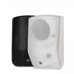
MQ 50i is a 2 way compact loudspeaker for indoor wall flush-mounting
installation.
Its “bass-reflex” (/ vented) cabinet includes a 5” woofer and a waveguide-
loaded dome tweeter (to ensure a sound correct dispersion over a wide
coverage angle).
It includes a transformer inside for the connection to (100 – 70 V) constant
voltage lines, yet it can also be set to 16 Ω (low impedance connection).
The power / mode selection is made by means of the front panel rotary switch.
Its power is:
a. 30-20-10-5 W (selectable) on 100 V constant voltage line.
b. 15-10-5-2.5 W (selectable) on 70 V constant voltage line.
c. Max. 60 W on low impedance (16 Ω).
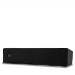
Its cabinet is made of high density polystyrene with a painted steel protection
grille.
It can be mounted on a flush-mounting box type “Multibox” (2 modules) by
BTicino® (or equivalent).
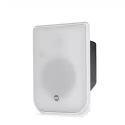
It has a rear metallic cover with a cable guide (for installation on plasterboard
or other types of panels).
MQ 50i is available in white only (MQ 50i-W).
WARNING: loudspeaker connections should be only made by qualified and
experienced personnel having the technical know-how or sufficient specific
instructions (to ensure that connections are made correctly) in order to prevent
any electrical danger.
To prevent any risk of electric shock, do not connect loudspeakers when the
amplifier is switched on. Before turning the system on, check all connections
and make sure there are no accidental short circuits. The entire sound system
shall be designed and installed in compliance with the current local laws and
regulations regarding electrical systems.
CONNECTION AND PRESETTING

5
ENGLISH
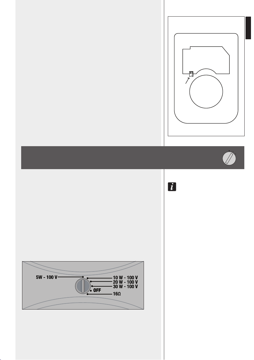
POWER ROTARY SWITCH
The input terminal is on the printed circuit board, close to the transformer.
Connect the line positive wire (coming from the amplifier output usually
marked “100 V”, “+” or “a”) to the “+” loudspeaker terminal.
Connect the line negative wire (coming from the amplifier output usually
marked “0”, “-”, “COM” or “b”) to the “-” loudspeaker terminal.
Fig. 1
NOTES:
uSE a ScrEwdrivEr TO TurN ThE rOTary SwiTch;
if ThE SwiTch iS SET TO Off, ThE lOudSpEakEr will bE muTEd.
a. 100 V (OR 70 V) CONSTANT VOLTAGE LINES
Set the rotary switch to the desired power value
(referred to 100 V) among 5 – 10 – 20 – 30 W.
If the line is 70 V (instead of 100 V), the power will be halved
(2.5 – 5 – 10 – 15 W).
b. LOW IMPEDANCE CONNECTION
Set the rotary switch to the 16 Ω position.
6
ENGLISH
INSTALLATION NOTES
Loudspeakers are to be installed by qualified personnel, respecting all safety
standards.
Loudspeakers are to be installed securely.
Make sure the supporting structure (i.e. plasterboards / wood panels) has the
necessary mechanical characteristics for the loudspeaker weight, without the
risk of a fall that could damage things or cause an injury.
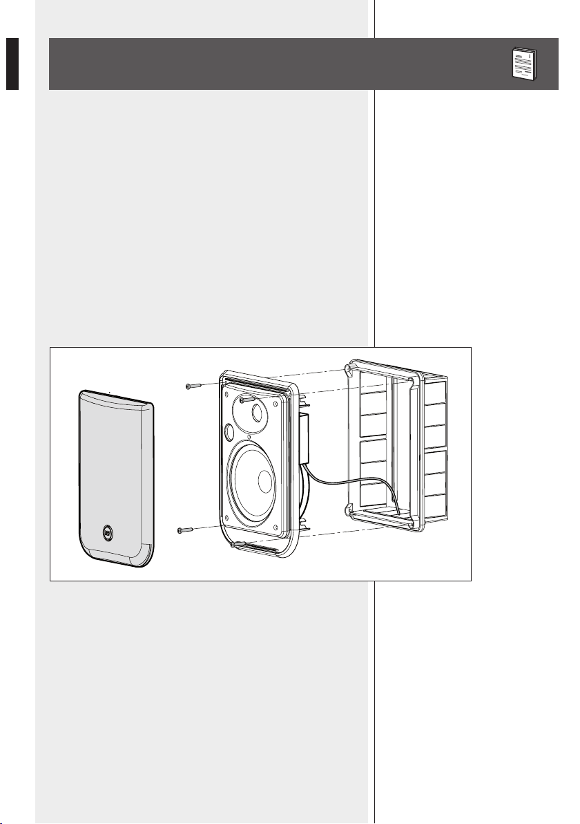
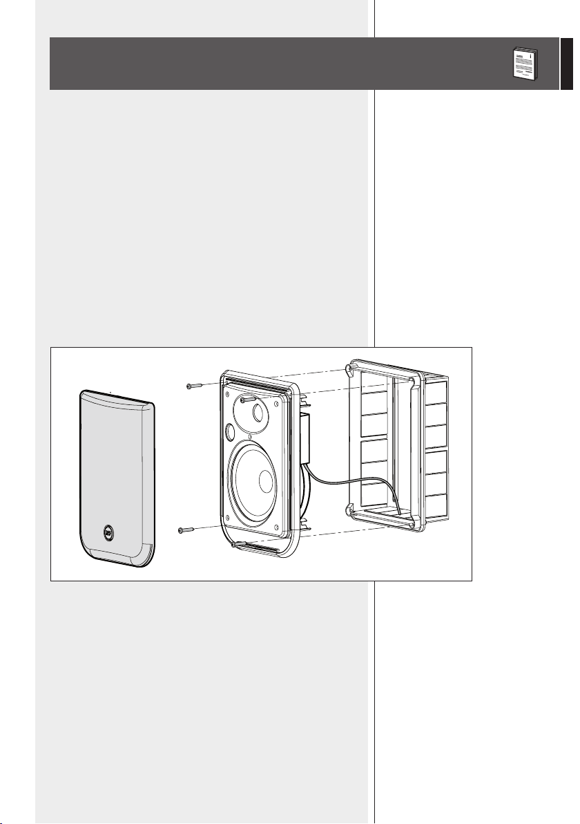
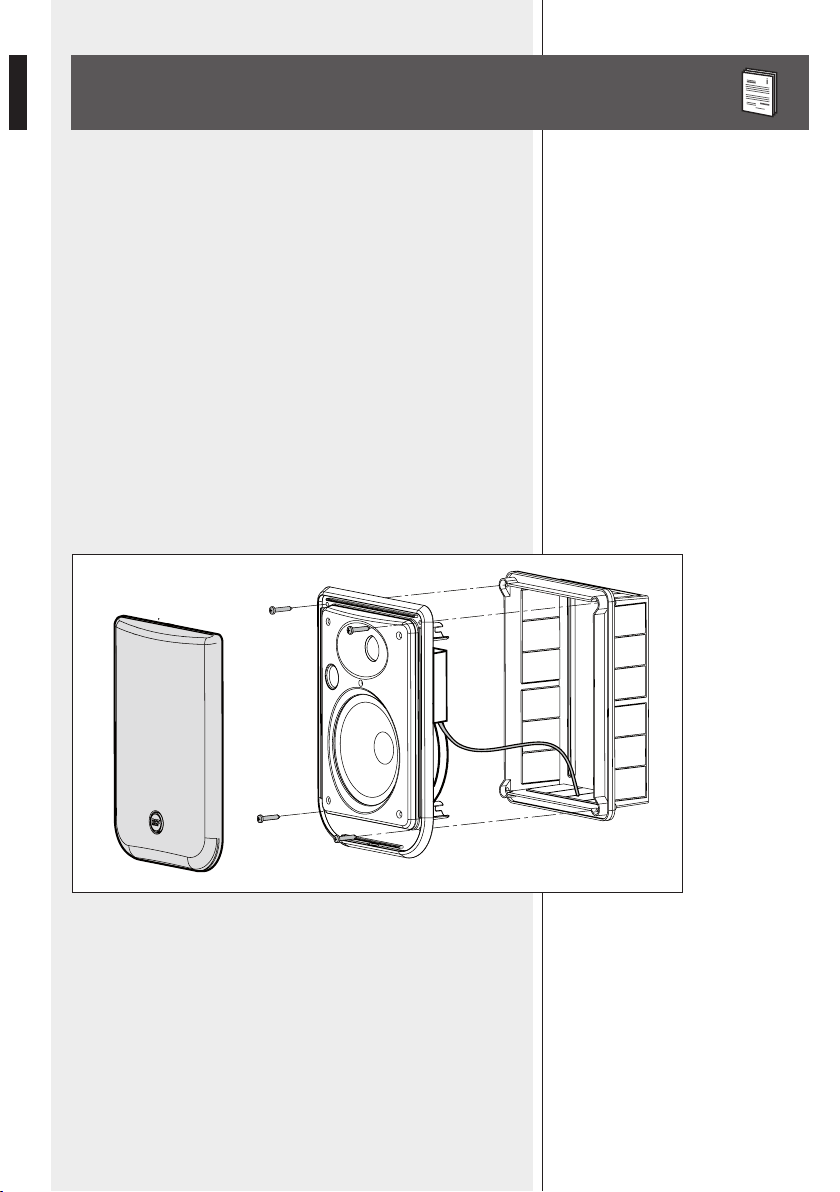
INSTALLATION ON A FLUSH-MOUNTING BOX TYPE “MULTIBOX”
(2 MOD.) BY BTICINO® (CODE 16102) OR EQUIVALENT
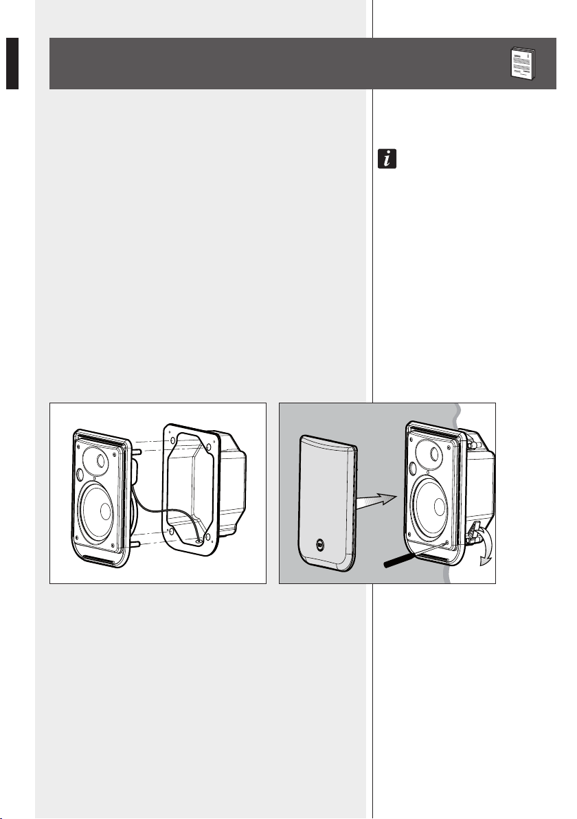
After connecting the loudspeaker (putting the cable through the flush-
mounting box) and setting the desired power value (by means of the front
panel rotary switch), fix the loudspeaker to the box with the 4 screws (as
shown in the drawing) and then add the front grille.
7
ENGLISH
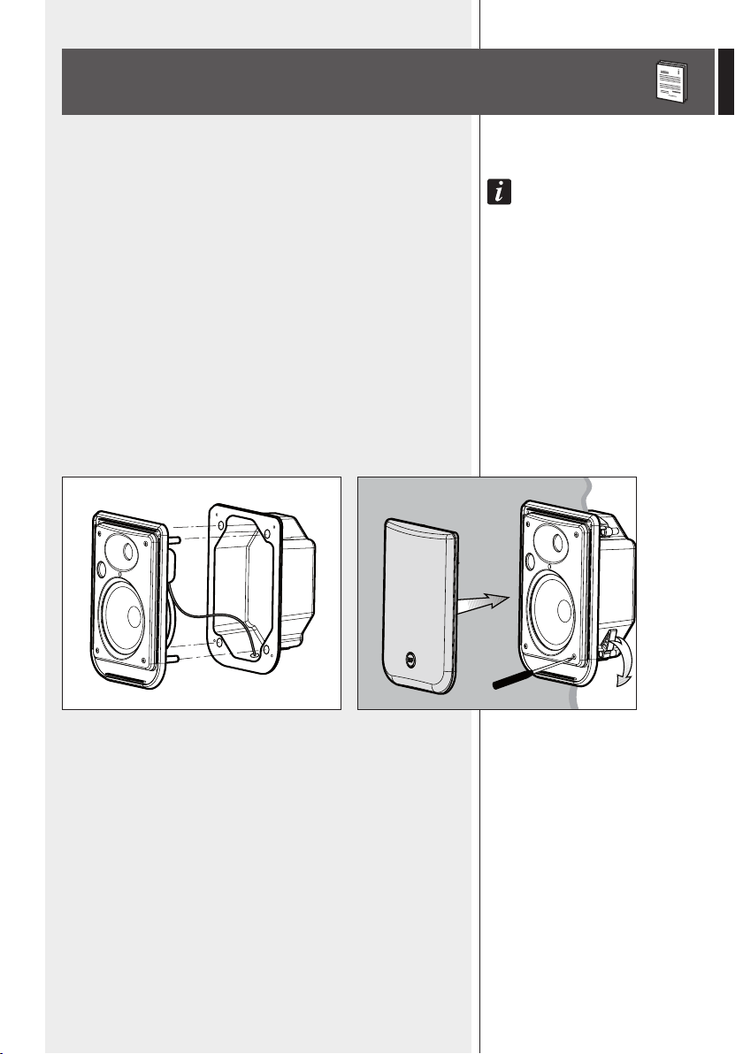
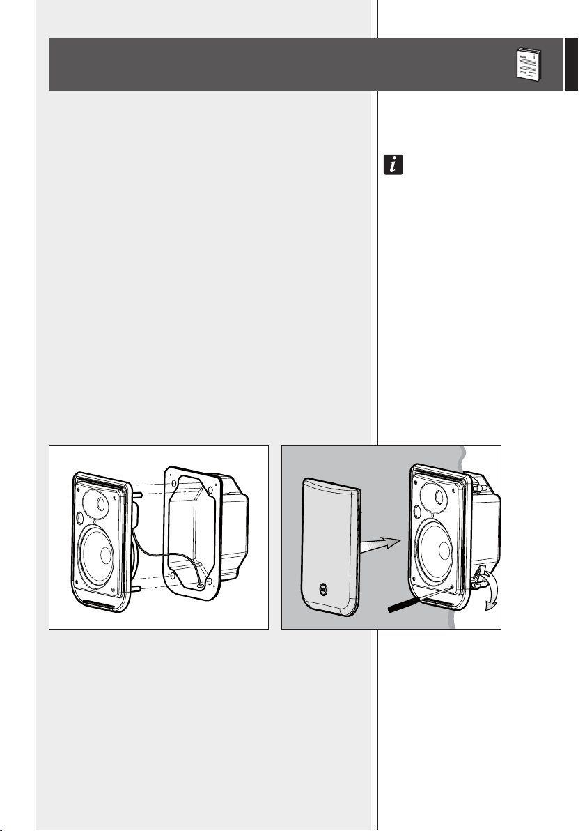
INSTALLATION WITH THE REAR
METALLIC COVER
Use the (included) rear metallic cover in case of the loudspeaker is to be
installed on plasterboards or other panel types.
NOTE: makE SurE ThErE iS ENOugh rOOm (aT lEaST 90 mm) ON ThE rEar SidE.
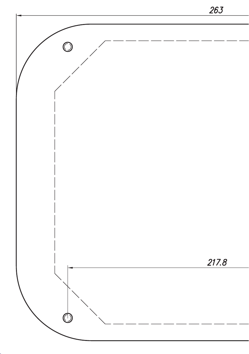
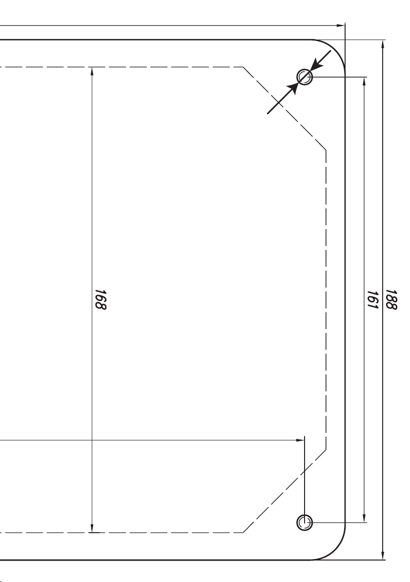
1. Make a 163 mm (w) x 228 mm (h) hole in the plasterboard.
2. Connect the loudspeaker and fix it to the rear metallic cover. The cable shall
pass through the rear cover cable guide.
3. Put the 4 screws into the loudspeaker and add (at the screw end) the rear
attachment terminals (at the rest initial position).
4. Insert the loudspeaker into the plasterboard / panel and then screw the 4
screws until the relevant attachment terminals tighten / fix it.
5. Set the power value (through the front panel rotary switch) and then add
the front grille.
8
ENGLISH
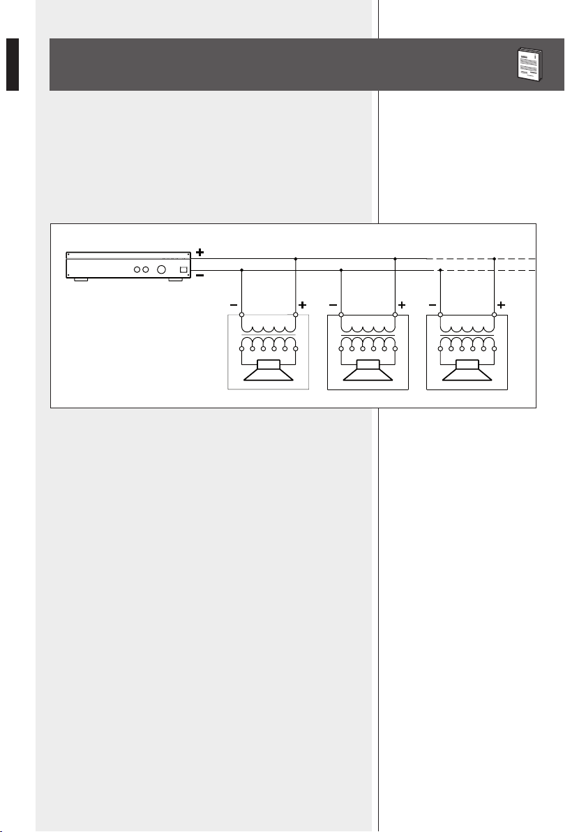
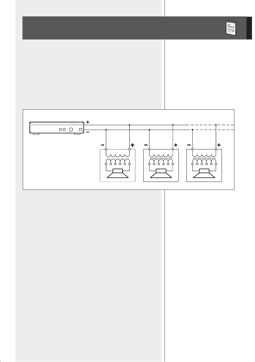
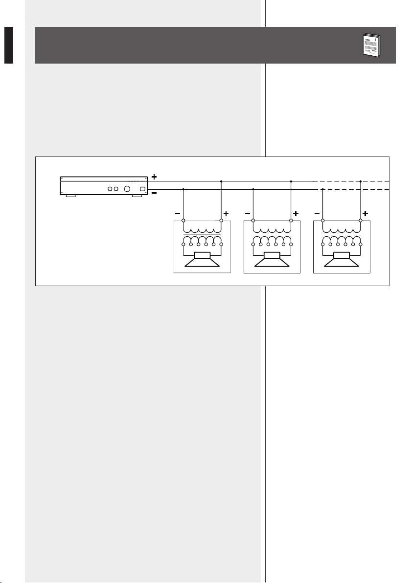
NOTES ABOUT CONSTANT VOLTAGE SYSTEMS
- The loudspeaker input voltage (Vd) shall correspond to the amplifier output
voltage (Va).
- The sum of nominal power values (Pd x n) of all loudspeakers connected to
the line shall not exceed the amplifier power (Pa).
- Make sure all loudspeakers are connected in phase to ensure a correct audio
reproduction.
AMPLIFIER
Pa = Amplifier power
Pd = Speaker power
n = Number of speakers
Vd = Speaker input voltage
Va = Amplifier output voltage
Pa > Pd x n Va
Vd=Va Vd=Va Vd=Va
9
ENGLISH
ADDITIONAL NOTES
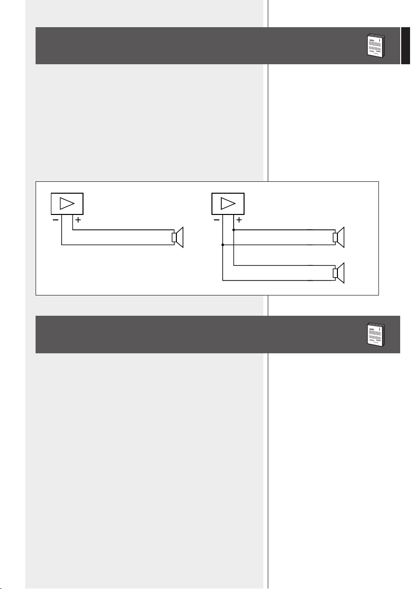
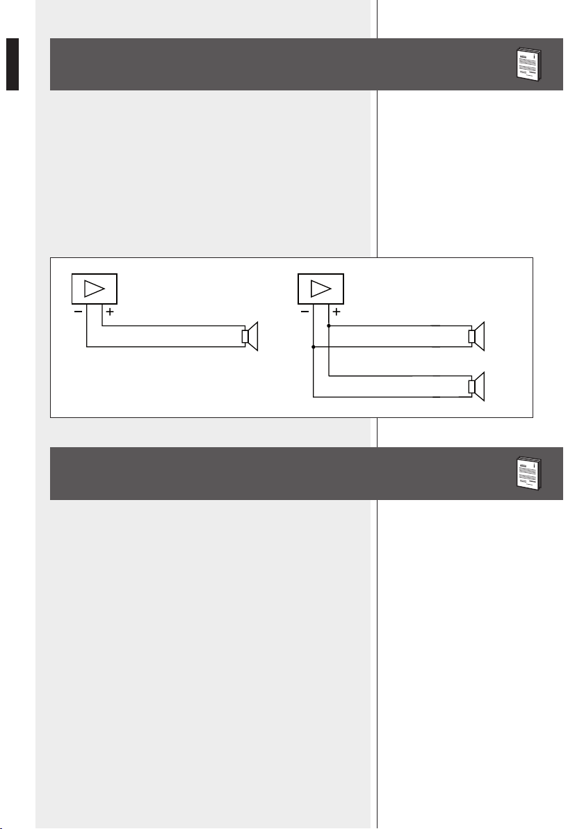
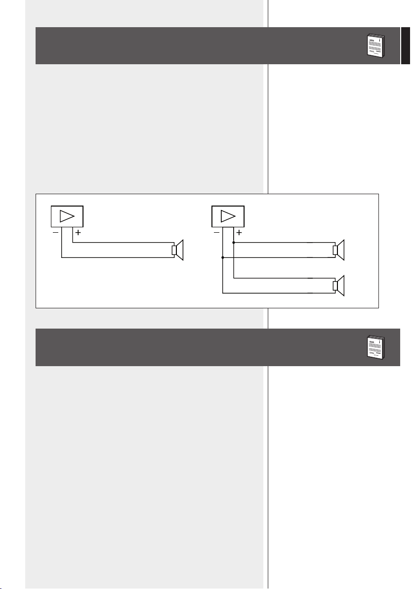
NOTES ABOUT LOW IMPEDANCE CONNECTIONS
- The total loudspeaker impedance must not be lower than the amplifier
output impedance. Note: a loudspeaker total impedance equal to the
amplifier output one permits to get the maximum deliverable power (but an
higher loudspeaker impedance entails less power).
- The total loudspeaker power shall be adequate for the maximum deliverable
power of the amplifier.
- The loudspeaker line shall be short (for long distances, it may be necessary
to use cables with large cross-section wires).
TOTAL IMPEDANCE: 16 Ω
16 Ω
TOTAL IMPEDANCE: 8 Ω
16 Ω
16 Ω
+
+
+
- Always use cables having wires with an adequate cross-section, considering
the cable length and the total loudspeaker power.
- Loudspeaker lines must be kept separated from mains cable, microphone
cables or others, in order to avoid inductive phenomena may cause hum
or noises.
- Use loudspeaker cables having twisted wires to reduce hum caused by
inductive effects due to coupling with electromagnetic fields.
- Do not set the rotary switch to the 16 Ω position when the loudspeaker is
connected to a (100 – 70 V) constant voltage line.

10
ENGLISH
SPECIFICATIONS
TYPE
LOUDSPEAKERS
CROSSOVER FREQUENCY
COVERAGE ANGLE
SENSITIVITY
MAX. SOUND PRESSURE
INPUT VOLTAGE
POWER
FREQUENCY RESPONSE
CABINET
DIMENSIONS (W, H, D)
REQUIRED WALL / CEILING
THICKNESS FOR THE INSTALLATION
NET WEIGHT
COLOUR
ACCESSORIES
2 way bass-reflex (vented) for flush-mounting
5” woofer, 0.75” dome tweeter
3 kHz
120° horizontal, 100° vertical
90 dB (1 W, 1 m)
108 dB (60 W)
100 – 70 V
- 30-20-10-5 W (100 V)
- 15-10-5-2.5 W (70 V)
- max. 60 W (16 Ω)
180 Hz ÷ 20 kHz
high density polystyrene
195 mm, 270 mm
Depth:
- with BTicino® 16102 box 72 mm
- with rear metallic cover 90 mm
min. 10 mm; max. 26 mm
3 kg
white (MQ 50i – W)
rear metallic cover
11
ITALIANO
AVVERTENZE PER LA SICUREZZA
IMPORTANTE
ATTENZIONE
IMPORTANTE
Prima di collegare ed utilizzare questo prodotto, leggere attentamente
le istruzioni contenute in questo manuale, il quale è da conservare per
riferimenti futuri. Il presente manuale costituisce parte integrante del
prodotto e deve accompagnare quest’ultimo anche nei passaggi di
proprietà, per permettere al nuovo proprietario di conoscere le modalità
d’installazione e d’utilizzo e le avvertenze per la sicurezza.
L’installazione e l’utilizzo errati del prodotto esimono la
RCF S.p.A. da ogni
responsabilità.
ATTENZIONE: Per prevenire i rischi di fiamme o scosse elettriche, non esporre
il diffusore alla pioggia o all’umidità ed alle polveri, salvo il caso in cui questo
sia stato espressamente progettato e costruito con un grado di protezione IP
adeguato (evidenziato nella documentazione tecnica del dispositivo).
AVVERTENZE PER LA SICUREZZA
1. Tutte le avvertenze, in particolare quelle relative alla sicurezza, devono
essere lette con particolare attenzione, in quanto contengono importanti
informazioni.
2. La linea diffusori (uscita dell’amplificatore) può avere una tensione
sufficientemente alta (es. 100 V) da costituire un rischio di folgorazione per le
persone: non procedere mai all’installazione o alla connessione del
diffusore quando la linea diffusori è in tensione.
3. Assicurarsi che tutte le connessioni siano corrette e che la tensione
d’ingresso (in un sistema a tensione costante) oppure l’impedenza del
diffusore sia compatibile con le caratteristiche d’uscita dell’amplificatore.
4. Accertarsi che la linea diffusori non possa essere calpestata o schiacciata da
oggetti, al fine di salvaguardarne la perfetta integrità.
5. Impedire che oggetti o liquidi entrino all’interno del prodotto, perché
potrebbero causare un corto circuito.
6. Non eseguire sul prodotto interventi / modifiche / riparazioni se non quelle
espressamente descritte sul manuale istruzioni.
Contattare centri di assistenza autorizzati o personale altamente qualificato
quando:
- Il diffusore non funziona (o funziona in modo anomalo);
- il cavo è danneggiato;
- oggetti o liquidi sono entrati nel diffusore;
- il diffusore non è più integro (a causa di urti / incendio).
7. Nel caso che dal diffusore provengano odori anomali o fumo, togliere
immediatamente la tensione dalla linea diffusori e poi scollegare il diffusore.
8. Non collegare a questo diffusore apparecchi ed accessori non previsti.
Quando è prevista l’installazione sospesa, utilizzare solamente gli appositi
punti di ancoraggio e non cercare di appendere il diffusore con elementi non
idonei o previsti allo scopo.

12
ITALIANO
Verificare inoltre l’idoneità del supporto (parete, soffitto, struttura ecc.) e
dei componenti utilizzati per il fissaggio (tasselli, viti, staffe non fornite da
RCF ecc.) che devono garantire la sicurezza dell’impianto / installazione nel
tempo, anche considerando, ad esempio, vibrazioni meccaniche normalmente
generate da un trasduttore.
9. La RCF S.p.A. raccomanda vivamente che l’installazione di questo
prodotto sia eseguita solamente da installatori professionali
qualificati (oppure da ditte specializzate) in grado di farla
correttamente e certificarla in accordo con le normative vigenti.
Tutto il sistema audio dovrà essere in conformità con le norme e le
leggi vigenti in materia di impianti elettrici.
10. Vi sono numerosi fattori meccanici ed elettrici da considerare quando si
installa un sistema audio professionale (oltre a quelli prettamente acustici, come
la pressione sonora, gli angoli di copertura, la risposta in frequenza, ecc.).
11. PERDITA DELL’UDITO
L’esposizione ad elevati livelli sonori può provocare la perdita permanente
dell’udito. Il livello di pressione acustica pericolosa per l’udito varia
sensibilmente da persona a persona e dipende dalla durata dell’esposizione.
Per evitare un’esposizione potenzialmente pericolosa ad elevati livelli di
pressione acustica, è necessario che chiunque sia sottoposto a tali livelli utilizzi
delle adeguate protezioni; quando si fa funzionare un trasduttore in grado di
produrre elevati livelli sonori è necessario indossare dei tappi per orecchie o
delle cuffie protettive.
Consultare i dati tecnici contenuti nel manuale istruzioni per conoscere la
massima pressione sonora che il diffusore acustico è in grado di produrre.
12. I diffusori devono essere collegati in fase (corrispondenza delle polarità
+/- tra amplificatori e diffusori) in modo da garantire una corretta riproduzione
audio, soprattutto quando i diffusori sono collocati in posizione fra loro
adiacente o nello stesso ambiente.
13. Per evitare che fenomeni induttivi diano luogo a ronzii, disturbi e
compromettano il buon funzionamento dell’impianto, le linee diffusori non
devono essere canalizzate insieme ai conduttori dell’energia elettrica, ai cavi
microfonici, alle linee di segnale a basso livello che fanno capo ad amplificatori.
14. Il cavo per il collegamento del diffusore dovrà avere conduttori di sezione
adeguata (possibilmente intrecciati, per minimizzare gli effetti induttivi dovuti
all’accoppiamento con campi elettro-magnetici circostanti) ed un isolamento
idoneo.
PRECAUZIONI D’USO
- Collocare il diffusore lontano da fonti di calore.
- Non forzare mai gli organi di comando (tasti, manopole ecc.).
- Non usare solventi, alcool, benzina o altre sostanze volatili per la pulitura
delle parti esterne.
- Se il diffusore viene utilizzato in ambienti particolarmente freddi, pilotarlo
con un segnale a basso livello per 5-10 minuti, prima di utilizzarlo alla
massima potenza.
PRECAUZIONI D’USO
13
ITALIANO
DESCRIZIONE
RCF S.P.A. VI RINGRAZIA PER L’ACQUISTO DI QUESTO PRODOTTO,
REALIZZATO IN MODO DA GARANTIRNE L’AFFIDABILITÀ E
PRESTAZIONI ELEVATE.
MQ 50i è un diffusore compatto per interno adatto per l’installazione ad
incasso a parete.
Si tratta di una cassa a 2 vie “bass-reflex”, avente un woofer da 5” ad alta
escursione con sospensione in gomma ed un tweeter a cupola morbida
caricato su guida d’onda (per assicurare una dispersione corretta del suono su
un ampio angolo di copertura).
Il diffusore è provvisto di trasformatore interno per il collegamento con linee
a tensione costante (100 V – 70 V), ma può anche essere impostato a bassa
impedenza 16 Ω (l’impostazione avviene tramite selettore posto sul pannello
frontale).
La potenza del diffusore è:
a) 30-20-10-5 W (selezionabile), con linea a tensione costante 100V;
b) 15-10-5-2,5 W (selezionabile), con linea a tensione costante 70 V;
c) max. 60 W con collegamento a bassa impedenza 16 Ω.
Il corpo del diffusore è in polistirene ad alta densità con griglia in acciaio
verniciato.
Il diffusore può essere montato su scatola standard per impianti elettrici
“Multibox” 2 moduli BTicino® (o equivalente) ed è corredato di custodia
posteriore in metallo con passacavo a tenuta (per applicazioni su pareti in
cartongesso od altro tipo di pannelli).
Il diffusore è disponibile solo in bianco (MQ 50i -W).
ATTENZIONE: per il collegamento del diffusore si raccomanda di rivolgersi
a personale qualificato ed addestrato, ossia personale avente conoscenze
tecniche o esperienza o istruzioni specifiche sufficienti per permettergli di
realizzare correttamente le connessioni e prevenire i pericoli dell’elettricità.
Per evitare il rischio di shock elettrici, non collegare il diffusore con
l’amplificatore acceso.
Prima di far funzionare il diffusore, è buona norma ricontrollare tutte le
connessioni, verificando attentamente che non vi siano dei cortocircuiti
accidentali. Tutto l’impianto di sonorizzazione dovrà essere realizzato in
conformità con le norme e le leggi vigenti in materia di impianti elettrici.
COLLEGAMENTO ED IMPOSTAZIONE

14
ITALIANO
SELETTORE DELLA POTENZA
Il connettore d’ingresso è sul circuito stampato dove si trova il trasformatore.
Collegare il conduttore positivo della linea (che fa capo all’uscita
dell’amplificatore solitamente contrassegnata con “100 V”, “+” oppure “a”)
al morsetto “+” del diffusore; collegare il conduttore negativo della linea (che
fa capo all’uscita dell’amplificatore solitamente contrassegnata con “0”, “-”,
“COM” oppure “b”) al morsetto “-” del diffusore.
Fig. 1
NOTE:
uTilizzarE uN cacciaviTE pEr EffETTuarE l’impOSTaziONE;
SE il SElETTOrE è Su Off, il diffuSOrE è SpENTO.
a. LINEE A TENSIONE COSTANTE 100 V (OPPURE 70 V)
Posizionare il selettore sul valore desiderato di potenza
(riferito alla tensione 100 V) tra 5 – 10 – 20 – 30 W.
Se la linea è 70 V (anziché 100 V), la potenza erogata è dimezzata
(2,5 – 5 – 10 – 15 W).
b. COLLEGAMENTO A BASSA IMPEDENZA
Posizionare il selettore su 16 Ω .
15
ITALIANO
NOTE SULL’INSTALLAZIONE
L’installazione dei diffusori deve essere effettuata da personale qualificato
rispettando gli standard di sicurezza. Eseguire un’installazione sicura di ogni
diffusore, controllando che la struttura di supporto (la parete / il pannello) abbia
le necessarie caratteristiche meccaniche, tali da consentirle di sopportarne il
peso senza il pericolo di cadute che potrebbero compromettere l’incolumità di
persone e/o danneggiare cose.
INSTALLAZIONE SU SCATOLA STANDARD PER IMPIANTI ELETTRICI
“MULTIBOX” 2 MODULI (CODICE BTICINO® 16102) O EQUIVALENTE
Dopo aver effettuato il collegamento (facendo passare il cavo attraverso la
scatola incassata a muro) ed impostato la potenza (tramite l’apposito selettore
frontale), fissare il diffusore alla scatola tramite 4 viti (come mostrato nel
disegno) e dopo aggiungere la griglia frontale.


18
Installation/installazione/installation
Ø 5.5 mm


22
ITALIANO
INSTALLAZIONE CON CUSTODIA
POSTERIORE METALLICA
Nel caso il diffusore debba essere installato su pareti in cartongesso od
altro tipo di pannelli, occorre utilizzare la custodia posteriore metallica (in
dotazione).
NOTa: aSSicurarSi chE lO SpaziO libErO pOSTEriOrE Sia almENO 90 mm .
1. Fare un buco di dimensioni 163 mm (l) x 228 mm (h) nella parete in
cartongesso.
2. Dopo aver effettuato il collegamento (facendo passare il cavo attraverso
il passacavo della custodia posteriore), inserire il diffusore nella custodia
metallica posteriore.
3. Inserire le 4 viti nel diffusore ed attaccarvi i morsetti di bloccaggio posteriori
(in posizione iniziale).
4. Inserire il diffusore nella parete e poi avvitare le 4 viti in modo che i morsetti
posteriori blocchino il diffusore alla parete.
5. Impostare la potenza (tramite l’apposito selettore frontale) e poi aggiungere
la griglia frontale.
23
ITALIANO
NOTE SUI SISTEMI A TENSIONE COSTANTE
- La tensione d’ingresso del diffusore (Vd) deve corrispondere con la tensione
d’uscita dell’amplificatore (Va).
- La somma delle potenze nominali di tutti i diffusori (Pd x n) collegati alla
linea non deve superare quella dell’amplificatore (Pa).
- Per garantire una corretta riproduzione audio, effettuare il collegamento di
tutti i diffusori “in fase”.
AMPLIFICATORE
Pa = Potenza amplificatore
Pd = Potenza diffusore
n = Numero diffusori
Vd = Tensione ingresso diffusore
Va = Tensione uscita amplificatore
Pa > Pd x n Va
Vd=Va Vd=Va Vd=Va
24
ITALIANO
ALTRE NOTE
NOTE SUI SISTEMI CON CONNESSIONE
A BASSA IMPEDENZA
- L’impedenza totale dei diffusori non deve essere inferiore a quella d’uscita
dell’amplificatore; nota: l’impedenza complessiva dei diffusori uguale a
quella d’uscita dell’amplificatore permette l’erogazione della massima
potenza (mentre un’impedenza superiore comporta una riduzione della
potenza erogata).
- La somma delle potenze dei diffusori deve essere adeguata alla potenza
massima erogabile dall’amplificatore.
- La lunghezza delle linee diffusori deve essere ridotta al minimo (una lunga
distanza può comportare l’uso di cavi con sezioni elevate).
TOTAL IMPEDANCE: 16 Ω
16 Ω
TOTAL IMPEDANCE: 8 Ω
16 Ω
16 Ω
+
+
+
- Utilizzare dei cavi con conduttori aventi una sezione adeguata, considerando
la loro lunghezza e la potenza complessiva dei diffusori.
- Per evitare che fenomeni induttivi diano luogo a ronzii, disturbi e
compromettano il funzionamento del sistema, i cavi per i diffusori non
devono essere canalizzati assieme ai conduttori dell’energia elettrica, ai
cavi microfonici od altre linee.
- Per minimizzare gli effetti induttivi (ronzii) dovuti all’accoppiamento con
campi elettromagnetici circostanti, utilizzare cavi con conduttori intrecciati.
- Non porre il selettore nella posizione 16 Ω quando il diffusore è collegato
ad una linea a tensione costante (100 – 70 V).
TIPO
ALTOPARLANTI
FREQUENZA DI CROSSOVER
ANGOLO DI COPERTURA
SENSIBILITÀ
MAX. PRESSIONE SONORA
TENSIONE D’INGRESSO
POTENZA
RISPOSTA IN FREQUENZA
CORPO
DIMENSIONI (L, H)
SPESSORE DELLA PARETE / SOFFITTO
RICHIESTO PER L’INSTALLAZIONE
PESO NETTO
COLORE
ACCESSORI

25
ITALIANO
DATI TECNICI
TIPO
ALTOPARLANTI
FREQUENZA DI CROSSOVER
ANGOLO DI COPERTURA
SENSIBILITÀ
MAX. PRESSIONE SONORA
TENSIONE D’INGRESSO
POTENZA
RISPOSTA IN FREQUENZA
CORPO
DIMENSIONI (L, H)
SPESSORE DELLA PARETE / SOFFITTO
RICHIESTO PER L’INSTALLAZIONE
PESO NETTO
COLORE
ACCESSORI
2 vie bass-reflex (per incasso)
woofer 5”; tweeter 0,75” a cupola
3 kHz
120° orizzontale, 100° verticale
90 dB (1 W, 1 m)
108 dB (60 W)
100 – 70 V
30-20-10-5 W (100 V)
15-10-5-2,5 W (70 V)
max. 60 W (16 Ω)
180 Hz ÷ 20 kHz
polistirene ad alta densità
195 mm, 270 mm
Profondità:
- con scatola BTicino® 16102 72 mm
- con custodia posteriore met. 90 mm
min. 10 mm; max. 26 mm
3 kg
bianco (MQ 50i – W)
custodia posteriore metallica

26
DEUTSCH
SICHERHEITSHINWEISE
WICHTIGE HINWEISE
ACHTUNG
WICHTIGE HINWEISE:
Bevor Sie dieses Gerät in Betrieb nehmen, lesen Sie die Bedienungsanleitung
bitte sorgfältig durch und halten Sie diese zur weiteren Einsichtnahme
bereit. Die Bedienungsanleitung sollte als wesentlicher Bestandteil dieses
Produkts verstanden werden und sollte diesem auch dann beiliegen,
wenn das Gerät den Besitzer wechselt, um eine korrekte Installation und
Benutzung zu gewährleisten sowie um als Referenz für alle notwendigen
Sicherheitsvorkehrungen zu dienen. Eine unsachgemäße Installation und/ oder
Benutzung dieses Produkts befreit RCF S.p.A. von jeglicher Haftung.
ACHTUNG: Um die Gefahr eines Brandes oder eines Stromschlags
auszuschließen, setzen Sie den Lautsprecher niemals Regen, Feuchtigkeit oder
Staub aus, es sei denn, dieser wurde ausdrücklich für diesen Einsatzzweck
entwickelt und gefertigt und weist den entsprechenden IP-Schutzgrad auf.
(Dieser ist den Produktspezifikationen zu entnehmen.)
SICHERHEITSHINWEISE
1. Alle Anweisungen, im Besonderen die sicherheitsrelevanten, müssen
mit besonderer Aufmerksamkeit gelesen werden, da sie entscheidende
Informationen enthalten.
2. An Lautsprecherleitungen (bzw. Verstärkerausgängen) liegt eine ausreichend
hohe Spannung an (100 V), um einen tödlichen Stromschlag zu verursachen.
Schließen Sie den Lautsprecher niemals an oder installieren Sie
diesen, wenn Spannung an seiner Leitung anliegt.
3. Stellen Sie vor dem Einschalten sicher, dass alle Anschlüsse korrekt
vorgenommen wurden und dass die Eingangsspannung des Lautsprechers
(bei Systemen mit Konstantspannung) oder seine Impedanz auf die des
anliegenden Verstärkerausgangs abgestimmt ist.
4. Schützen Sie das Lautsprecherkabel vor Beschädigungen. Stellen Sie sicher,
dass dieses so positioniert wird, dass nicht darauf getreten oder es von
Gegenständen eingedrückt werden kann.
5. Stellen Sie sicher, dass keine Gegenstände oder Flüssigkeiten ins Innere des
Geräts gelangen können, da dies zu einem Kurzschluss führen kann.
6. Versuchen Sie niemals das Gerät auf eine Weise einzusetzen oder
Modifikationen und Reparaturen an diesem durchzuführen, die nicht
ausdrücklich in dieser Bedienungsanleitung beschrieben werden.
Kontaktieren Sie Ihr autorisiertes Service-Center oder qualifiziertes
Fachpersonal, sollte eines der folgenden Ereignisse auftreten:
- Das Gerät funktioniert nicht (oder funktioniert nicht korrekt).
- Das Kabel wurde beschädigt.
- Gegenstände oder Flüssigkeiten sind ins Innere des Geräts gelangt.
- Der Lautsprecher wurde durch einen heftigen Stoß oder einen Brand
beschädigt.
7. Sollte von dem Lautsprecher ein ungewohnter Geruch oder Rauch ausgehen,
schalten Sie diesen unverzüglich aus und trennen Sie das Anschlusskabel.

27
DEUTSCH
8. Verbinden Sie das Produkt nur mit dafür vorgesehenen Geräten und
Zubehörteilen.
Nutzen Sie für eine hängende Installation ausschließlich die vorgesehenen
Verankerungspunkte und versuchen Sie nicht, das Produkt mit für diesen Zweck
ungeeigneten Montageelementen zu befestigen. Prüfen Sie zudem die Eignung
der Stützfläche (Wand, Decke, Baustruktur etc.) und des Befestigungsmaterials
(Dübel, Schrauben, Winkel etc., nicht im Lieferprogramm von RCF), um die
langfristige Sicherheit des Systems sowie seiner Installation zu gewährleisten.
Berücksichtigen Sie dabei beispielsweise auch die mechanischen Vibrationen,
die gewöhnlich von einem akustischen Strahler ausgehen.
9. RCF S.p.A. empfiehlt nachdrücklich, die Installation dieses Geräts
ausschließlich von qualifiziertem Fachpersonal (oder spezialisierten
Firmen) durchführen zu lassen, die eine korrekte Installation
sicherstellen und diese gemäß der geltenden Bestimmungen
zertifizieren können.
Das gesamte Beschallungssystem muss den geltenden Standards
und Vorschriften für elektrische Anlagen entsprechen.
10. Bei der Installation einer professionellen Beschallungsanlage müssen
neben rein akustischen Parametern (wie etwa Schalldruck, Abdeckungswinkel,
Frequenzgang etc.) einige mechanische und elektrische Faktoren beachtet
werden.
11. Gehörschädigung
Die Einwirkung hoher Lautstärkepegel kann zu dauerhaften Gehörschädigungen
führen. Der Schalldruckpegel, der zu einer Schädigung des Gehörs führt,
unterscheidet sich von Person zu Person und ist von der Dauer der Einwirkung
abhängig. Um potentielle Gefahren durch hohe Schalldruckpegel zu
vermeiden, sollte jeder, der diesen Pegeln ausgesetzt ist, einen geeigneten
Gehörschutz verwenden. Beim Einsatz eines leistungsfähigen Schallerzeugers,
der hohe Lautstärkepegel erzeugt, ist es erforderlich Gehörschutzstöpsel oder
Ohrenschützer zu tragen.
12. Um eine korrekte Musikwiedergabe zu gewährleisten, ist die Phasenlage
der Lautsprecher zu berücksichtigen (so auch die Polarität der Verstärker
beim Anschluss der Lautsprecher). Dies ist entscheidend, wenn Lautsprecher
nebeneinander aufgestellt werden, zum Beispiel innerhalb eines Raums.
13. Um das Auftreten von Induktionseffekten wie Brummen oder Störgeräusche
und Fehlfunktionen zu vermeiden, platzieren Sie die Lautsprecherkabel nicht in
der Nähe von Netzstromkabeln oder Lautsprecherleitungen.
14. Die Leiter des Lautsprecherkabels müssen einen angemessenen
Querschnitt (wenn möglich, verdrillte Adern zur Minimierung induktiver
Effekte, die von umliegenden elektromagnetischen Feldern erzeugt werden)
sowie eine ausreichende elektrische Isolierung aufweisen.
SICHERHEITSMASSNAHMEN FÜR DEN BETRIEB
- Install this loudspeaker far from any heat source.
- Do not overload this product for extended periods of time.
- Never force the control elements (keys, knobs, etc. ).
- Do not use solvents, alcohol, benzene or other volatile substances for
cleaning the external parts of this product.
- If the speaker is used in particulary cold places, drive it with a low signal for
5-10 minutes before using it at maximum power.
SICHERHEITSMASSNAHMEN FÜR
DEN BETRIEB

28
DEUTSCH
EINFÜHRUNG
R.C.F S.P.A. DANKT IHNEN FÜR DEN KAUF DIESES PRODUKTS,
DAS AUF HÖCHSTE ZUVERLÄSSIGKEIT UND LEISTUNGSFÄHIGKEIT
AUSGELEGT IST.
Der MQ 50i ist ein 2-Wege-Kompaktlautsprecher zur Unterputzmontage
in Innenräumen. Das ventilierte Bassreflex-Gehäuse verfügt über einen
5” Woofer (Tieftöner) sowie einem 25 mm (1”) horngeladenen Dome-
Tweeter (Hochtöner), die eine optimale Abstrahlung über einen breiten
Abdeckungswinkel gewährleisten.
Der Lautsprecher ist mit einem Übertrager ausgestattet, der einen direkten
Anschluss an Linien mit Konstantspannung (100 - 70 V) sowie niederohmige
Verbindungen bei 16 Ω ermöglicht.
Ausgangsleistung und Betriebsmodus können mithilfe eines Drehschalters auf
der Gerätevorderseite ausgewählt werden.
Der MQ 50i verfügt über folgende Leistungsmodi:
a. 30 - 20 - 10 - 5 W an Linien mit 100 V Konstantspannung
b. 15 - 10 - 5 - 2,5 W an Linien mit 70 V Konstantspannung
c. max. 60 W an niederohmigen Verbindungen (16 Ω).
Das Gehäuse des MQ 50i besteht aus hochdichtem Polystyrol und verfügt über
ein lackiertes Schutzgitter aus Stahl.
Es kann mithilfe eines Unterputzkastens des Typs „Multibox“ (Module 2) von
BTicino® (oder vergleichbar) montiert werden.
Zudem verfügt das Gehäuse rückseitig über eine Metallabdeckung mit
Kabelführung (für eine Installation auf Gipskartonplatten oder anderen
Wandpaneelen).
Der MQ 50i ist in weiß erhältlich: MQ 50i - W
ACHTUNG: Das Anschließen der Lautsprecher sollte ausschließlich von
fachkundigen und erfahrenen Personen durchgeführt werden, die über
technisches Know-how und spezifische Instruktionen verfügen. So kann ein
korrekter Anschluss sichergestellt und eine elektrische Gefährdung vermieden
werden.
Um die Gefahr eines Stromschlags auszuschließen, verbinden Sie den
Lautsprecher nicht im eingeschalteten Zustand mit dem Verstärker. Bevor
Sie den Lautsprecher in Betrieb nehmen, überprüfen Sie bitte sorgfältig, ob
alle Anschlüsse ordnungsgemäß vorgenommen wurden, um unbeabsichtigte
Kurzschlüsse zu verhindern. Die gesamte Beschallungsanlage muss den lokal
geltenden Standards und Vorschriften für elektrische Anlagen entsprechen.
ANSCHLUSS UND EINSTELLUNGEN
29
DEUTSCH
LEISTUNGSWAHLSCHALTER (DREHSCHALTER)
Die Eingangsanschlussklemme (Euroblock) befindet sich auf der Platine, in der
Nähe des Übertragers. Verbinden Sie die vom Verstärker kommende positive
Signalleitung (i. d. R. mit „100 V“, „+“ oder „a“ gekennzeichnet) mit der mit
„+“ markierten Anschlussklemme des Lautsprechers.
Verbinden Sie dann die vom Verstärker kommende negative Signalleitung (i. d.
R. mit „0“, „-“, „COM“ oder „b“ gekennzeichnet) mit der mit „-“ markierten
Anschlussklemme des Lautsprechers.
Fig. 1
hiNwEiSE:
vErwENdEN SiE EiNEN SchraubENziEhEr, um dEN drEhSchalTEr zu bETäTigEN. bEfiNdET Sich
dEr drEhSchalTEr iN Off-STElluNg, iST dEr lauTSprEchEr STummgESchalTET.
a. 100 V (70 V) KONSTANTSPANNUNGSLEITUNGEN
Wählen Sie mit dem Drehschalter die gewünschte Ausgangsleistung
(5 - 10 - 20 - 30 W) aus. Beträgt die Spannung 70 V (statt 100 V), halbiert
sich die Ausgangsleistung (2,5 - 5 - 10 - 15 W).
b. NIEDEROHMIGE VERBINDUNG
Wählen Sie mit dem Drehschalter die 16-Ohm-Stellung.
30
DEUTSCH
INSTALLATIONSHINWEISE
Die Lautsprecher müssen von fachkundigem Personal unter Berücksichtigung
aller Sicherheitsstandards installiert werden. Dabei ist eine sichere Befestigung
zu gewährleisten. Es wird dringend empfohlen zu prüfen, ob die Montagefläche
(Gipskartonplatten / Holzpaneele) über die nötigen mechanischen
Eigenschaften verfügt, um das Gewicht des Lautsprechers zu tragen. So
kann das Herunterfallen des Lautsprechers verhindert und Verletzungen oder
Sachschäden ausgeschlossen werden.
INSTALLATION IN UNTERPUTZKASTEN DES TYPS „MULTIBOX“
(MODUL 2) VON BTICINO® (MODELL: 16102) ODER EINER
VERGLEICHBAREN AUSFÜHRUNG
Nachdem das Anschlusskabel durch den Unterputzkasten geführt, der
Lautsprecher angeschlossen und die gewünschte Ausgangsleistung (mithilfe
des Drehschalters auf der Gerätevorderseite) ausgewählt wurde, fixieren
Sie den Lautsprecher mit den vier Schrauben am Einbaukasten (wie in der
Abbildung dargestellt) und befestigen Sie das Frontschutzgitter.
31
DEUTSCH
INSTALLATION IN RÜCKSEITIGEM
METALLGEHÄUSE
Verwenden Sie das (im Lieferumfang enthaltene) Metallgehäuse, wenn der
Lautsprecher auf Gipskartonplatten oder anderen Wandpaneelen installiert
werden soll.
hiNwEiS: STEllEN SiE SichEr, daSS auf dEr rückSEiTE gENügENd raum (miNdESTENS 90 mm)
zur vErfüguNg STEhT.
1. Machen Sie ein Loch mit einer Größe von 163 mm (B) x 228 mm (H) an der
für den Einbau des Lautsprechers gewählten Stelle in die Gipskartonplatte.
2. Schließen Sie den Lautsprecher an und setzen Sie diesen in das Metallgehäuse
ein. Das Kabel sollte durch den Kabelschacht des Metallgehäuses verlegt
werden.
3. Setzen Sie die vier Schrauben und die Befestigungshaken (am Ende jeder
Schraube) ein und bringen Sie diese in Ausgangsposition.
4. Setzen Sie den Lautsprecher in die Gipskartonplatte/ das Wandpaneel und
fixieren Sie diesen durch Festziehen der vier Schrauben.
5. Stellen Sie die gewünschte Ausgangsleistung (mithilfe des Drehschalters auf
der Gerätevorderseite) ein und befestigen Sie das Schutzgitter.
32
DEUTSCH
HINWEISE ZU SYSTEMEN MIT KONSTANTSPANNUNG
- Die Eingangsspannung jedes Lautsprechers (Vd) muss mit der
Ausgangsspannung des Verstärkers (Va) übereinstimmen.
- Die Gesamtnennleistung (Pd x n) aller angeschlossenen Lautsprecher darf
die Leistung des Verstärkers nicht überschreiten.
- Um eine korrekte Audiowiedergabe zu gewährleisten, müssen alle
Anschlüsse phasengleich (in Phase) vorgenommen werden.
VERSTÄRKER
Pa = Verstärkerleistung
Pd = Lautsprecherleistung
n = Anzahl der Lautsprecher
Vd = Eingangsspannung der Lautsprecher
Va = Ausgangsspannung des Verstärkers
Pa > Pd x n Va
Vd=Va Vd=Va Vd=Va
33
DEUTSCH
ZUSÄTZLICHE HINWEISE
HINWEISE ZU NIEDEROHMIGEN VERBINDUNGEN
- Die Gesamtimpedanz der Lautsprecher darf nicht unterhalb der
Ausgangsimpedanz des Verstärkers liegen. Hinweis: Entspricht die
Gesamtimpedanz der Lautsprecher genau der Ausgangsimpedanz des
Verstärkers, kann die maximale Leistung übertragen werden (eine höhere
Impedanz der Lautsprecher führt jedoch zu einer geringeren Leistung).
- Die Gesamtleistung der Lautsprecher muss der maximalen
Verstärkerleistung entsprechen.
- Die Lautsprecherverbindungen sollten möglichst kurz sein. (Für längere
Distanzen kann es nötig sein, Kabel mit großen Leitungsquerschnitten zu
verwenden.)
GESAMTIMPEDANZ: 16 Ω
16 Ω
GESAMTIMPEDANZ: 8 Ω
16 Ω
16 Ω
+
+
+
- Nutzen Sie stets Leitungen mit geeignetem Querschnitt unter
Berücksichtigung der Kabellänge sowie der Gesamtleistung aller
angeschlossenen Lautsprecher.
- Um das Aufkommen von Brummen und Störgeräuschen zu verhindern, die
von induktiven Effekten verursacht werden, sollten die Lautsprecherkabel
nicht in der Nähe von Netzkabeln, Mikrofonkabeln oder sonstigen
Leitungen verlegt werden.
- Um induktive Effekte (Brummen) zu minimieren, die von umliegenden
elektrischen Feldern ausgehen, sollten ausschließlich Lautsprecherkabel
mit verdrillten Adern verwendet werden.
- Stellen Sie den Drehschalter nicht in die 16 Ω - Position, wenn der
Lautsprecher an einer Leitung mit Konstantspannung (70 - 100 V)
betrieben wird.

34
DEUTSCH
TECHNISCHE DATEN
LAUTSPRECHERTYP
LAUTSPRECHER
TRENNFREQUENZ (CROSSOVER)
ABSTRAHLUNGSWINKEL
EMPFINDLICHKEIT
MAX. SCHALLDRUCKPEGEL
EINGANGSSPANNUNG
LEISTUNG
FREQUENZGANG
GEHÄUSE
ABMESSUNGEN (B, H, T)
ERFORDERLICHE WAND-/ DECKENSTÄRKE
FÜR DIE INSTALLATION
GEWICHT (NETTO)
FARBE
ZUBEHÖR
ventilierter 2-Wege Bassreflexlautsprecher für Unterputzmontage
5“ Woofer (Tieftöner), 0,75“ Dome-Tweeter (Hochtöner)
3 kHz
120° horizontal, 100° vertikal
90 dB (1 W,1 m)
108 dB (60 W)
100 - 70 V
- 30 - 20 - 10 - 5 (100 V)
- 15 - 10 - 5 - 2,5 (70 V)
180 Hz - 20 kHz
Hart-Polystyrol
195, 270 mm
Tiefe:
- mit BTicino (16102) Gehäuse: 72 mm
- mit rückseitigem Metallgehäuse: 90 mm
min. 10 mm, max. 26 mm
3 kg
Weiß (MQ 50i - W)
rückseitiges Metallgehäuse


10307142 rev.C - EN_IT_DE
www.rcfaudio.com
HEADQUARTERS:
RCF S.p.A. Italy
tel. +39 0522 274 411
e-mail: info@rcf.it
RCF UK
tel. 0844 745 1234
Int. +44 870 626 3142
e-mail: [email protected].uk
RCF France
tel. +33 1 49 01 02 31
e-mail: france@rcf.it
RCF Germany
tel. +49 2203 925370
e-mail: germany@rcf.it
RCF Spain
tel. +34 91 817 42 66
e-mail: [email protected]
RCF Belgium
tel. +32 (0) 3 - 3268104
e-mail: belgium@rcf.it
RCF USA Inc.
tel. +1 (603) 926-4604
e-mail: [email protected]