
USER MANUAL
MANUALE D’USO
BEDIENUNGSANLEITUNG
MQ 50
TWO-WAY COMPACT
MONITOR SPEAKER
SYSTEM
DIFFUSORE MONITOR
COMPATTO A DUE VIE
KOMPAKTES
ZWEIWEGE-MONITOR-
LAUTSPRECHERSYSTEM

2
ENGLISH
SAFETY PRECAUTIONS
IMPORTANT NOTES
WARNING
IMPORTANT NOTES
Before connecting and using this product, please read this instruction manual
carefully and keep it on hand for future reference. The manual is to be
considered an integral part of this product and must accompany it when it
changes ownership as a reference for correct installation and use as well as
for the safety precautions.
RCF S.p.A. will not assume any responsibility for the incorrect installation and
/ or use of this product.
WARNING: To prevent the risk of fire or electric shock, never expose this
loudspeaker to rain or humidity and dust, but the case this has been expressly
designed and made to get a suitable IP protection grade (indicated in the
product specifications).
SAFETY PRECAUTIONS
1. All the precautions, in particular the safety ones, must be read with special
attention, as they provide important information.
2. Loudspeaker lines (amplifier outputs) can have a sufficiently high voltage
(i.e. 100 V) to involve a risk of electrocution: never install or connect this
loudspeaker when the line is alive.
3. Make sure all connections have been made correctly and the loudspeaker
input voltage (in a constant voltage system) or its impedance is suitable for
the amplifier output.
4. Protect loudspeaker lines from damage; make sure they are positioned in a
way that they cannot be stepped on or crushed by objects.
5. Make sure that no objects or liquids can get into this product, as this may
cause a short circuit.
6. Never attempt to carry out any operations, modifications or repairs that are
not expressly described in this manual.
Contact your authorized service centre or qualified personnel should any of
the following occur:
- the loudspeaker does not function (or works in an anomalous way);
- the cable has been damaged;
- objects or liquids have got into the unit;
- the loudspeaker has been damaged due to heavy impacts / fire.
7. Should the loudspeaker emit any strange odours or smoke, remove it from
the line after having switched the amplifier off.
8. Do not connect this product to any equipment or accessories not foreseen.
For suspended installation, only use the dedicated anchoring points and do
not try to hang this loudspeaker by using elements that are unsuitable or not
specific for this purpose.
Also check the suitability of the support surface to which the product is anchored
(wall, ceiling, structure, etc.), and the components used for attachment (screw

3
ENGLISH
anchors, screws, brackets not supplied by RCF etc.), which must guarantee the
security of the system / installation over time, also considering, for example,
the mechanical vibrations normally generated by transducers.
9. RCF S.p.A. strongly recommends this product is only installed
by professional qualified installers (or specialised firms) who
can ensure a correct installation and certify it according to the
regulations in force. The entire audio system must comply with the
current standards and regulations regarding electrical systems.
10. There are numerous mechanical and electrical factors to be considered
when installing a professional audio system (in addition to those which
are strictly acoustic, such as sound pressure, angles of coverage, frequency
response, etc.).
11. HEARING LOSS
Exposure to high sound levels can cause permanent hearing loss. The acoustic
pressure level that leads to hearing loss is different from person to person
and depends on the duration of exposure. To prevent potentially dangerous
exposure to high levels of acoustic pressure, anyone who is exposed to these
levels should use adequate protection devices. When a transducer capable of
producing high sound levels is being used, it is therefore necessary to wear ear
plugs or protective earphones.
See the technical specifications in the instruction manual for the maximum
sound pressure the loudspeaker is capable of producing.
12. To ensure a correct musical reproduction, loudspeaker phase is to be
respected (loudspeakers are connected respecting the amplifier polarity).
This is important when loudspeakers are installed adjacent one another, for
instance, in the same room.
13. To prevent inductive effects from causing hum, noise and a bad system
working, loudspeaker lines should not be laid together with other electric
cables (mains), microphone or line level signal cables connected to amplifier
inputs.
14. The loudspeaker cable shall have wires with a suitable section (twisted,
if possible, to reduce inductive effects due to surrounding electro-magnetic
fields) and a sufficient electrical insulation.
OPERATING PRECAUTIONS
- Install this loudspeaker far from any heat source.
- Do not overload this product for extended periods of time.
- Never force the control elements (keys, knobs, etc. ).
- Do not use solvents, alcohol, benzene or other volatile substances for
cleaning the external parts of this product.
- If the speaker is used in particulary cold places, drive it with a low signal for
5-10 minutes before using it at maximum power.
OPERATING PRECAUTIONS
4
ENGLISH
INTRODUCTION
MONITOR SPEAKER FOR INSTALLATION
AT CONSTANT DIRECTIVITY
RCF S.P.A. WOULD LIKE TO THANK YOU FOR HAVING PURCHASED THIS
PRODUCT, WHICH HAS BEEN DESIGNED TO GUARANTEE RELIABILITY
AND HIGH PERFORMANCE.
Building upon the solid tradition of the existing RCF Monitor Series Professional
Loudspeaker Systems, RCF are pleased to introduce the New Monitor Q Series.
The Monitor Q Series is an additional family to add to the outstanding
versatility of the RCF Monitor range of speakers. Our objectives are to provide
you with an additional choice of ‘cosmetically pleasing’ fashion orientated
compact installation speaker systems. Plus unique ‘Contractor Solutions’.
The Monitor Q Series offers modern industrial design along with impeccable
acoustic engineering with six installation specific models. RCF Engineers have
worked to create a true combination of design and acoustics with ‘installation
friendly’ mounting and fixing systems to please both the Sound Contractor,
architect and end client. For example the MQ 50 has a truly innovative speaker
fixing system which allows the contractor to wire in and terminate connections
via the bracket assembly during a ‘first fix’ part of the installation. Then simply
when the building project is complete the speaker and included termination
cable is simply plugged into the pre-fixed bracket assembly.
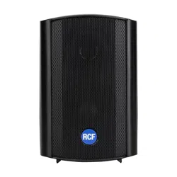
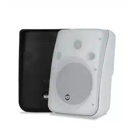
Available in White and some models also in Anthracite Grey.
All models can be easily re painted to match any décor.
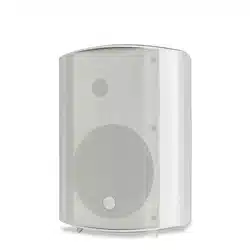
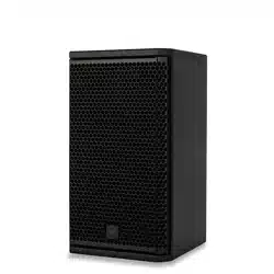
The MQ 50 is a monitor speaker for constant directivity installation. It is a two-
way speaker with 5” woofer and waveguide-loaded dome tweeter to ensure
intelligibility and correct dispersion of the sound over a wide angle of coverage.
The built-in support makes the MQ 50 easy to install and enables close fitting
to the wall, limiting its protrusion.
The exclusive attachment system designed for the MQ 50 model allows the
installer to fit the attachment bracket to the wall and make the electrical
connections during the pre-installation phase; subsequently, when all the
works are completed, the MQ 50 is positioned, oriented, and connected with
a simple “click”, without the need for tools.
5
ENGLISH
CONNECTIONS
To prevent the risk of electric shock, do not connect the speaker
with the amplifier switched on.
Before using the speaker, carefully check that all the connections have been
made correctly to make sure there are no accidental short circuits that could
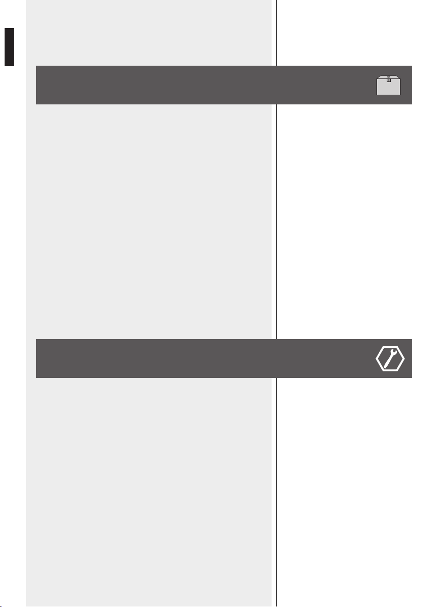
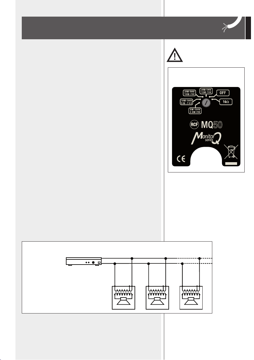
cause electrical sparks. The speaker can be connected to constant voltage
audio lines at 70 V or 100 V or to constant impedance lines (rotary switch
positioned to 16 Ohm).
1. Turn the rotary switch (Fig. 1) and select the voltage of the line and the
power to be delivered.
2. Connect the black conductor of the speaker to the “negative” (-) of the
audio line, that leads from the amplifier terminal marked -, 0 or COM tap
of the amplifier
3. Connect the other conductor of the speaker to the “positive” (+) conductor
of the audio line.
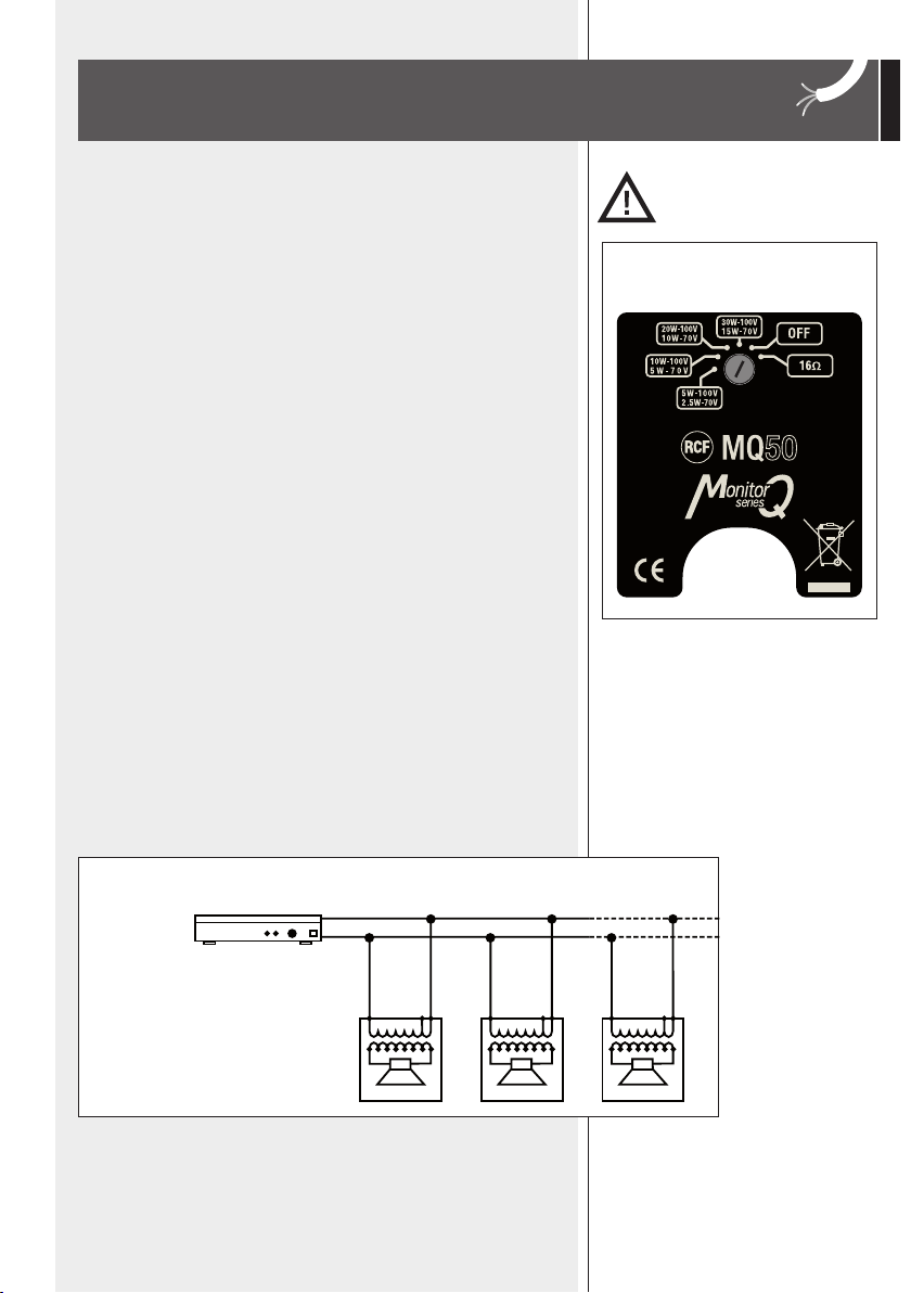
4. When making the connections, keep the following indications in mind
(Fig. 2, costant voltage).
- The input voltage selected on the speaker must correspond with the voltage
selected on the amplifier.
- The sum of the operating power values of all the speakers connected to the
audio line must not exceed that of the amplifier.
- To ensure correct audio reproduction, the connections should be made “in
phase”, where the +/- polarities of the amplifier output correspond with the
+/- polarities of the speaker input.
When two speakers reproduce the same frequencies but with phase differences,
these frequencies may be annulled. In sound systems, speakers are often
situated in adjacent positions and the sound waves produced interact with
each other. If a speaker is connected incorrectly; i.e. the polarity of the audio
line conductors is inverted, the audio signals are transmitted with differences
in phase and correct reproduction is therefore jeopardized.
Pa = Amplifier power
Pd = Speaker power
n = Number of speakers
Vd = Speaker input voltage
Va = Amplifier output voltage
Amplifier
Pa > Pd x n Va
Vd = Va
+
-
-
+
-
+
Vd = Va
Fig. 2
-
+
Vd = Va
Fig. 1
6
ENGLISH
For connecting the speaker use cables with an adequate cross-section. The
greater the distance between the amplifier and the speaker, the larger the
connection cable cross-section should be to limit the voltage loss along the
line.
To prevent inductive phenomena from giving rise to humming or disturbance
that jeopardize the effective operation of the audio system, the speaker cables
should not be run together with electrical energy conductors, microphone
cables, or low level audio lines (e.g. LINE level).
To facilitate the ‘’in phase’’ connection of the speaker, use bipolar cables that
have markings to
distinguish the polarity (e.g. insulation of different colours, conductors of
different colours, ect.).
To minimize the inductive effects (hum) due to coupling with surrounding
electrical fields, use cables with conductors braided together.
You are recommended to install the speaker
safety, checking that the fixing surface is
resistant and solid enough to support the weight of the
speaker, so as to prevent the risk of it falling that could
put the safety of persons and structures in jeopardy.
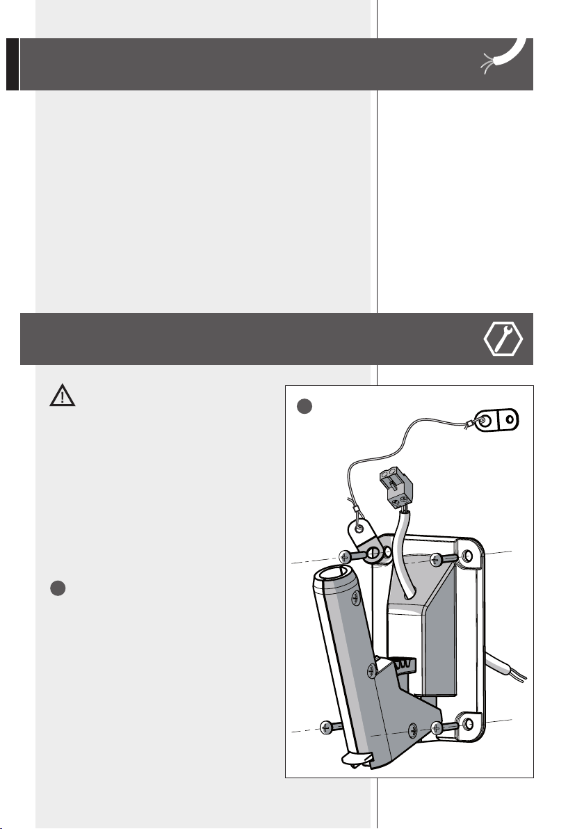
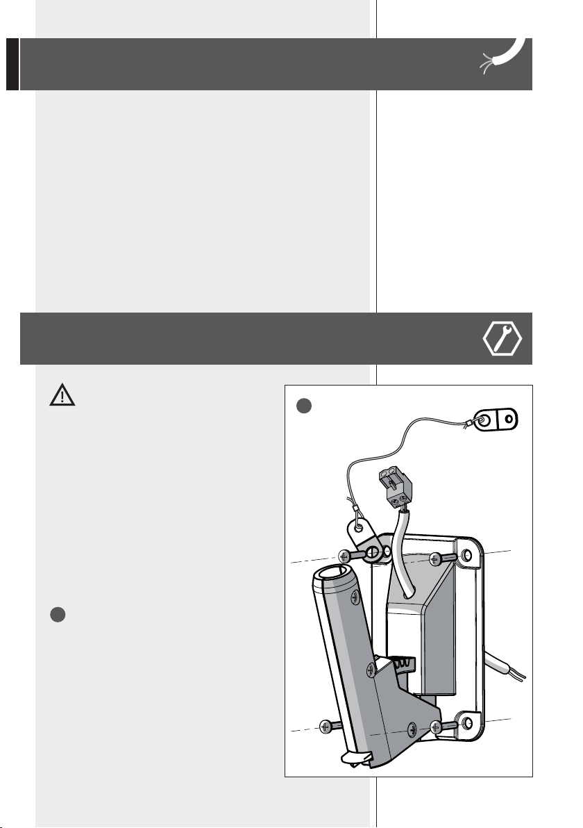
The accessory is installed as follows (see the figure):
Using suitable plugs and screws (not provided), fix the
support at the chosen point on the wall. The plugs to be
used must be chosen carefully depending on the type of
wall (plasterboard, hollow bricks, solid bricks, concrete,
matchboard panelling, etc.).
- Insert the cable through the mounting accessory
- Connect the cable to speaker line coming from
the amplifier
- Install the wall-mounting accessory by using
screws with max. diameter 5 mm (not provided).
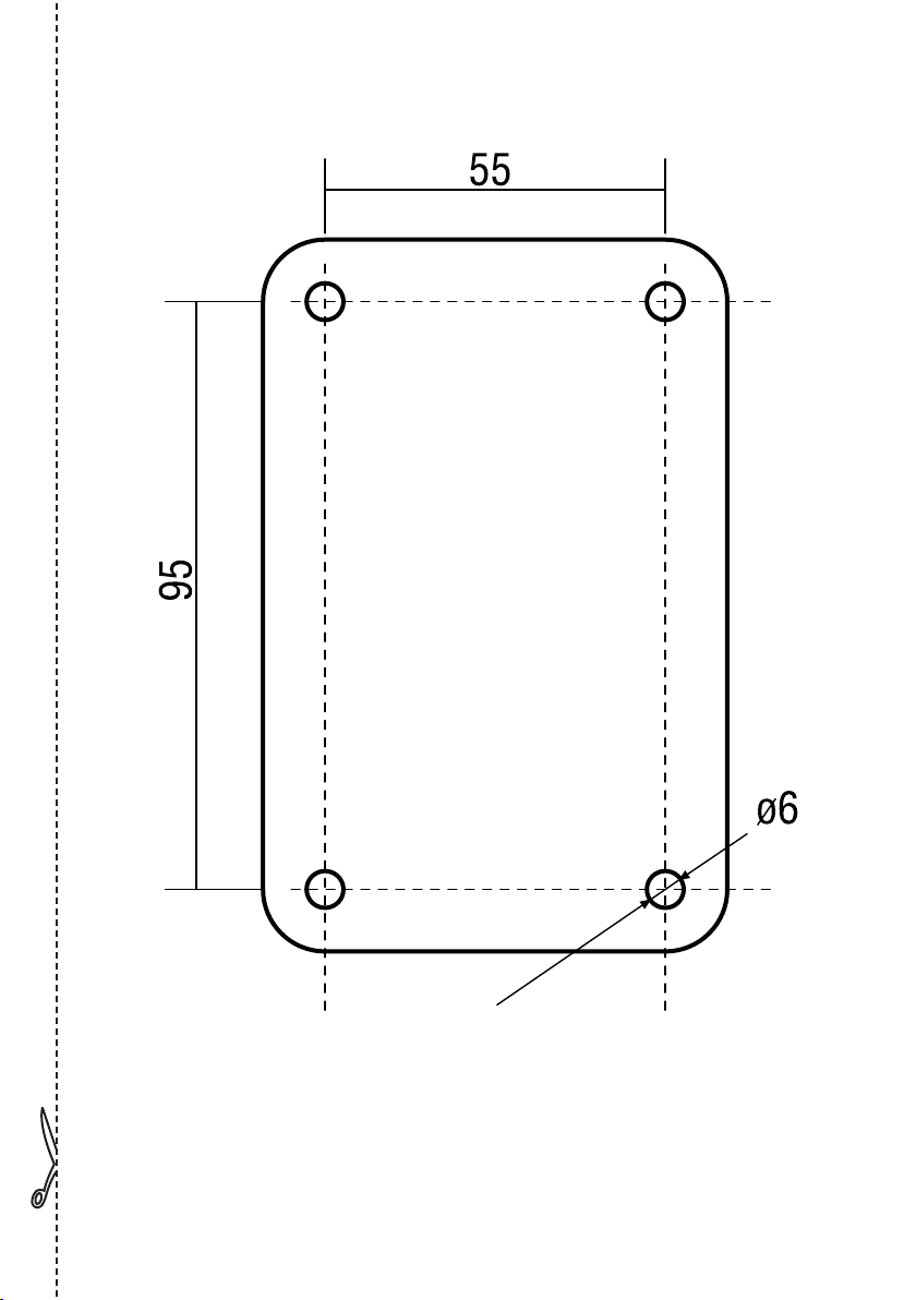
Note: there is a template for drilliNg at page 27.
the provided safety cable is to be fixed to oNe of the
four accessory screws.
INPUT CABLES
INSTALLATION INSTRUCTIONS
1
1

7
ENGLISH
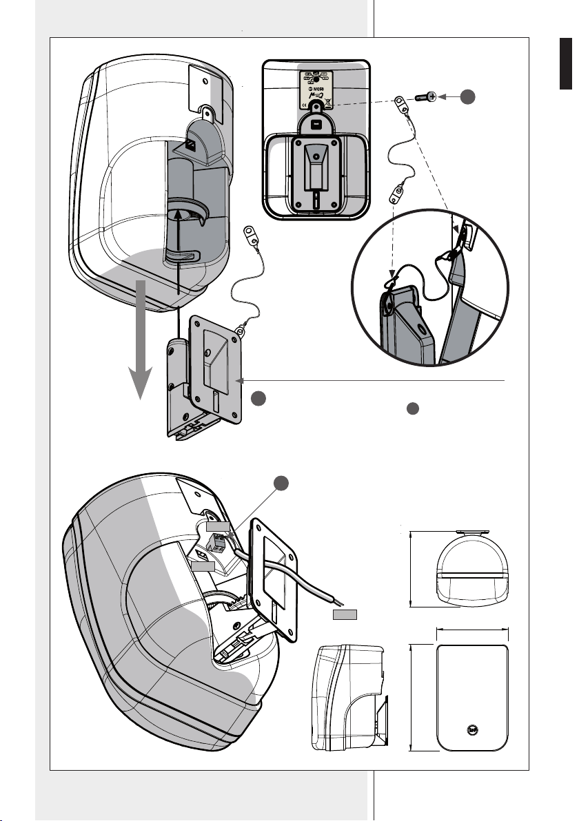
Insert the loudspeaker onto the wall-mounting accessory.
Anchor the other safety cable end to the loudspeaker by using
the supplied screw
S
, as shown in the figure.
Plug-in the
terminal into the
speaker.
165
245
175
2
+
–
+
–
3
+
–
S
8
ENGLISH
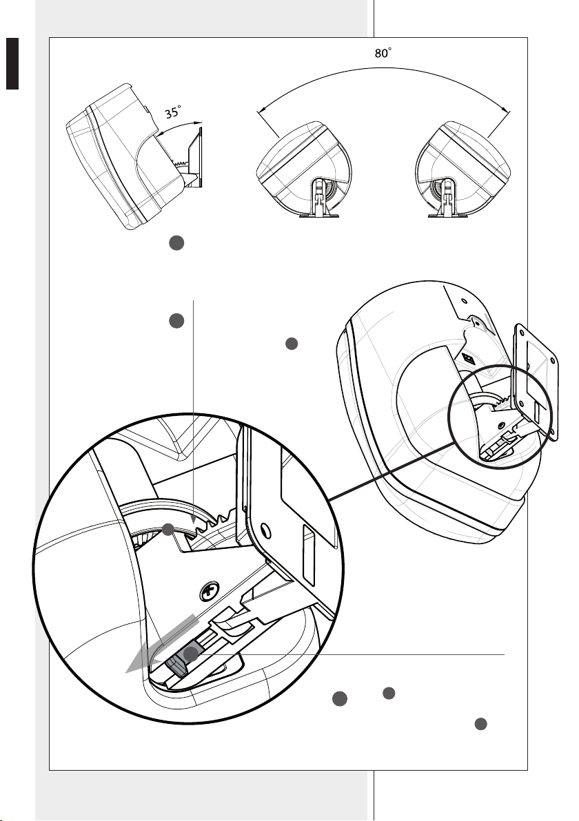
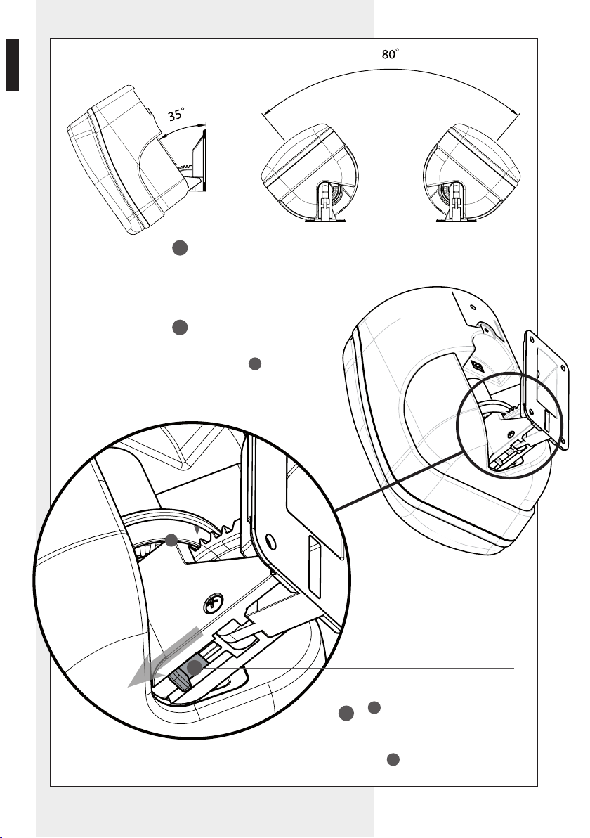
Make sure the tooth of the
chosen vertical tilt setting has
been properly/deeply inserted
into the circular seat
A
.
Then block the loudspeaker in the
desidered position by moving the
lever
B
towards the loudspeaker.
For aiming or removing the
loudspeaker, move the lever
B
towards the mounting accessory.
Aim the loudspeaker to get the desidered position.
4
5
B
6
A
9
ENGLISH
SPECIFICATIONS
TYPE OF SPEAKER:
SPEAKER:
SENSITIVITY:
FREQUENCY RESPONSE(-10dB):
SPL:
POWER/RMS:
CONSTANT VOLTAGE:
IMPEDANCE:
LINE TRANSFORMER:
CROSSOVER FREQUENCIES:
CROSSOVER:
ANGLE OF COVERAGE:
PROTEZIONI:
CABINET:
CONNECTORS:
DIMENSION (L X H X P):
COLOUR:
WEIGHT:
Two way Bass reflex
woofer 5” - tweeter 0,75” dome
89 dB SPL 1W/1m
70 - 20000 Hz
110 dB
120/60 W Bypass
70,7 - 100 V
[Bypass] 16 Ohm
[100V]: 333 Ω - 30 W, 500 Ω - 20 W, 1 kΩ - 10 W, 2 kΩ - 5 W
[70.7V]: 333 Ω - 15 W, 500 Ω - 10 W, 1 kΩ - 5 W, 2 kΩ - 2.5 W
4500 Hz
12/12 dB/oct
120° horizontal x 100° vertical
Dynamic on woofer and tweeter
Hi-density polystirene HB grade
Euroblock
160 x 240 x 130 mm
anthracite grey / white
3 Kg

10
ITALIANO
AVVERTENZE PER LA SICUREZZA
IMPORTANTE
ATTENZIONE
IMPORTANTE
Prima di collegare ed utilizzare questo prodotto, leggere attentamente le
istruzioni contenute in questo manuale, il quale è da conservare per riferimenti
futuri. Il presente manuale costituisce parte integrante del prodotto e deve
accompagnare quest’ultimo anche nei passaggi di proprietà, per permettere
al nuovo proprietario di conoscere le modalità d’installazione e d’utilizzo e le
avvertenze per la sicurezza.
L’installazione e l’utilizzo errati del prodotto esimono la RCF S.p.A. da ogni
responsabilità.
ATTENZIONE: Per prevenire i rischi di fiamme o scosse elettriche, non esporre
il diffusore alla pioggia o all’umidità ed alle polveri, salvo il caso in cui questo
sia stato espressamente progettato e costruito con un grado di protezione IP
adeguato (evidenziato nella documentazione tecnica del dispositivo).
AVVERTENZE PER LA SICUREZZA
1. Tutte le avvertenze, in particolare quelle relative alla sicurezza, devono
essere lette con particolare attenzione, in quanto contengono importanti
informazioni.
2. La linea diffusori (uscita dell’amplificatore) può avere una tensione
sufficientemente alta (es. 100 V) da costituire un rischio di folgorazione per le
persone: non procedere mai all’installazione o alla connessione del diffusore
quando la linea diffusori è in tensione.
3. Assicurarsi che tutte le connessioni siano corrette e che la tensione
d’ingresso (in un sistema a tensione costante) oppure l’impedenza del
diffusore sia compatibile con le caratteristiche d’uscita dell’amplificatore.
4. Accertarsi che la linea diffusori non possa essere calpestata o schiacciata da
oggetti, al fine di salvaguardarne la perfetta integrità.
5. Impedire che oggetti o liquidi entrino all’interno del prodotto, perché
potrebbero causare un corto circuito.
6. Non eseguire sul prodotto interventi / modifiche / riparazioni se non quelle
espressamente descritte sul manuale istruzioni.
Contattare centri di assistenza autorizzati o personale altamente qualificato
quando:
- Il diffusore non funziona (o funziona in modo anomalo);
- il cavo è danneggiato;
- oggetti o liquidi sono entrati nel diffusore;
- il diffusore non è più integro (a causa di urti / incendio).
7. Nel caso che dal diffusore provengano odori anomali o fumo, togliere
immediatamente la tensione dalla linea diffusori e poi scollegare il diffusore.
8. Non collegare a questo diffusore apparecchi ed accessori non previsti.
Quando è prevista l’installazione sospesa, utilizzare solamente gli appositi
punti di ancoraggio e non cercare di appendere il diffusore con elementi non
idonei o previsti allo scopo.

11
ITALIANO
Verificare inoltre l’idoneità del supporto (parete, soffitto, struttura ecc.) e
dei componenti utilizzati per il fissaggio (tasselli, viti, staffe non fornite da
RCF ecc.) che devono garantire la sicurezza dell’impianto / installazione nel
tempo, anche considerando, ad esempio, vibrazioni meccaniche normalmente
generate da un trasduttore.
9. La RCF S.p.A. raccomanda vivamente che l’installazione di questo
prodotto sia eseguita solamente da installatori professionali
qualificati (oppure da ditte specializzate) in grado di farla
correttamente e certificarla in accordo con le normative vigenti.
Tutto il sistema audio dovrà essere in conformità con le norme e le
leggi vigenti in materia di impianti elettrici.
10. Vi sono numerosi fattori meccanici ed elettrici da considerare quando
si installa un sistema audio professionale (oltre a quelli prettamente
acustici, come la pressione sonora, gli angoli di copertura, la risposta in
frequenza, ecc.).
11. PERDITA DELL’UDITO
L’esposizione ad elevati livelli sonori può provocare la perdita permanente
dell’udito. Il livello di pressione acustica pericolosa per l’udito varia
sensibilmente da persona a persona e dipende dalla durata dell’esposizione.
Per evitare un’esposizione potenzialmente pericolosa ad elevati livelli di
pressione acustica, è necessario che chiunque sia sottoposto a tali livelli utilizzi
delle adeguate protezioni; quando si fa funzionare un trasduttore in grado di
produrre elevati livelli sonori è necessario indossare dei tappi per orecchie o
delle cuffie protettive.
Consultare i dati tecnici contenuti nel manuale istruzioni per conoscere la
massima pressione sonora che il diffusore acustico è in grado di produrre.
12. I diffusori devono essere collegati in fase (corrispondenza delle polarità
+/- tra amplificatori e diffusori) in modo da garantire una corretta riproduzione
audio, soprattutto quando i diffusori sono collocati in posizione fra loro
adiacente o nello stesso ambiente.
13. Per evitare che fenomeni induttivi diano luogo a ronzii, disturbi e
compromettano il buon funzionamento dell’impianto, le linee diffusori non
devono essere canalizzate insieme ai conduttori dell’energia elettrica, ai cavi
microfonici, alle linee di segnale a basso livello che fanno capo ad amplificatori.
14. Il cavo per il collegamento del diffusore dovrà avere conduttori di sezione
adeguata (possibilmente intrecciati, per minimizzare gli effetti induttivi dovuti
all’accoppiamento con campi elettro-magnetici circostanti) ed un isolamento
idoneo.
PRECAUZIONI D’USO
- Collocare il diffusore lontano da fonti di calore.
- Non forzare mai gli organi di comando (tasti, manopole ecc.).
- Non usare solventi, alcool, benzina o altre sostanze volatili per la pulitura
delle parti esterne.
- Se il diffusore viene utilizzato in ambienti particolarmente freddi, pilotarlo
con un segnale a basso livello per 5-10 minuti, prima di utilizzarlo alla
massima potenza.
PRECAUZIONI D’USO
12
ITALIANO
INTRODUZIONE
DIFFUSORE MONITOR PER INSTALLAZIONE
A DIRETTIVITÀ COSTANTE
RCF S.P.A. VI RINGRAZIA PER L’ACQUISTO DI QUESTO PRODOTTO,
REALIZZATO IN MODO DA GARANTIRNE L’AFFIDABILITÀ E
PRESTAZIONI ELEVATE.
La sezione elettroacustica del settore ricerca e sviluppo RCF ha lavorato
assieme ad architetti e installatori al progetto Monitor Q. L’ambizioso obiettivo
qui raggiunto è stato quello di creare una linea di diffusori acusticamente
eccellenti, ma anche in grado di rappresentare delle vere e proprie soluzioni
alle esigenze di sonorizzazione di ambienti privati, commerciali e pubblici,
esigenze spesso dettate da vincoli architettonici e installativi.
Ogni modello della serie Q rappresenta la soluzione ad una esigenza di
sonorizzazione per ambienti commerciali, pubblici e privati quali la diffusione
di parlato e musica in uffici, bar & ristoranti, hotel, luoghi ricreativi, parchi a
tema, centri commerciali. I diffusori Monitor Q sono anche adatti per essere
impiegati in sistemi multimediali. Sono equipaggiati con trasformatore di linea
per sistemi a tensione costante ma utilizzabili in modo estremamente flessibile
anche a bassa impedenza, disponendo di connessione a 16 Ohm.
I diffusori Monitor Q sono quindi facili da installare, garantiscono una resa
audio superiore, consentono spesso la riduzione dei punti di installazione
e si inseriscono in ogni contesto di arredamento grazie anche all’impatto
estetico sempre discreto dovuto ad accorgimenti progettuali tesi a contenere
gli ingombri e la sporgenza da parete o soffitto. Grazie al family-look che
li caratterizza diversi modelli Monitor Q possono coesistere all’interno di
ambienti che richiedono/impongono l’utilizzo di diverse soluzioni installative.
I diffusori della serie Monitor Q sono disponibili in bianco ed alcuni modelli
anche in grigio antracite. Possono essere sovra-tinteggiati per adattarsi a
qualsiasi tipo di finitura.
L’ MQ 50 è un diffusore monitor da installazione. Si tratta di una cassa acustica
a 2 vie con woofer da 5” e tweeter a cupola caricato su guida d’onda per
assicurare intelligibilità e corretta dispersione del suono su un ampio angolo
di copertura.
Ha supporto integrato che lo rende facile da installare e ne consente il
montaggio aderente alla parete limitandone la sporgenza.
L’esclusivo sistema di fissaggio ideato per il modello MQ 50 permette
all’installatore di montare la staffa di fissaggio a muro e di effettuare
le connessioni elettriche durante la stessa fase di pre-installazione;
successivamente, a fine lavori, l’MQ 50 viene posizionato, orientato e collegato
senza l’impiego di attrezzi, semplicemente con un “click”.
13
ITALIANO
COLLEGAMENTI
Per evitare il rischio di shock elettrici, non collegare il diffusore con
l’amplificatore acceso.
Prima di far funzionare il diffusore verificare attentamente la correttezza dei
collegamenti, per evitare che cortocircuiti accidentali possano dare luogo a
scintille elettriche. Il diffusore può essere collegato a linee audio a tensione
costante a 70 V o 100 V oppure ad impedenza costante (commutatore rotativo
posizionato su 16 Ohm).
1. Ruotare il commutatore rotativo indicato in fig. 1 in modo da selezionare la
tensione della linea e la potenza da diffondere
2. Collegare il conduttore nero del diffusore al conduttore “negativo” (-) della
linea audio, che fa capo al morsetto dell’amplificatore contrassegnato con
0 o COM.
3. Collegare l’altro conduttore del diffusore, al conduttore “positivo” (+) della
linea audio.
4. Effettuare le connessioni tenendo in considerazione le seguenti indicazioni
(fig.2, tensione costante).
- la tensione d’ingresso selezionata sul diffusore deve corrispondere con la
tensione selezionata sull’uscita dell’amplificatore.
- la somma delle potenze di utilizzo di tutti i diffusori collegati alla linea audio
non deve superare quella dell’amplificatore.
- per garantire una corretta riproduzione audio effettuare un collegamento
“in fase”, che consiste nel fare corrispondere le polarità +/- dell’uscita
dell’amplificatore con le polarità +/- dell’ingresso del trasformatore.
Quando due diffusori riproducono le medesime frequenze ma con differenze di
fase, esiste la possibilità che tali frequenze si annullino. Spesso negli impianti
di sonorizzazione i diffusori vengono collocati in posizioni fra loro adiacenti, e
le onde sonore prodotte interagiscono fra loro; se un diffusore viene collegato
in modo errato, ossia viene invertita la polarità dei conduttori della linea audio,
i segnali audio vengono diffusi con differenze di fase, e la corretta riproduzione
viene quindi compromessa.
Fig. 1
Pa = Potenza amplificatore
Pd = Potenza diffusore
n = Numero diffusori
Vd = Tensione ingresso diffusore
Va = Tensione uscita amplificatore
Amplificatore
Pa > Pd x n Va
Vd = Va
+
-
-
+
-
+
Vd = Va
Fig. 2
-
+
Vd = Va
14
ITALIANO
Per il collegamento del diffusore utilizzare dei cavi aventi un’adeguata
sezione. Maggiore è la distanza fra l’amplificatore ed il diffusore, maggiore
dovrebbe essere la sezione dei cavi di collegamento per limitare le perdite di
segnale lungo la linea. Per evitare che fenomeni induttivi diano luogo a ronzii,
disturbi, e compromettano il buon funzionamento dell’impianto audio, i cavi
per diffusori non devono essere canalizzati assieme ai conduttori dell’energia
elettrica, ai cavi microfonici, o a linee audio a basso livello (es. livello LINEA).
Per facilitare il collegamento “in fase” del diffusore, utilizzare cavi bipolari
aventi una marcatura che ne distingua le polarità (es. isolante di colore diverso,
conduttori di colore diverso, ecc.).
Per minimizzare gli effetti induttivi (ronzii) dovuti all’accoppiamento con campi
elettrici circostanti, utilizzare cavi con i conduttori intrecciati fra loro.
Si raccomanda di eseguire un’installazione
sicura del diffusore, controllando che la
superficie di fissaggio abbia una resistenza e solidità
tale da supportare il peso del diffusore, in modo
da evitare cadute che potrebbero compromettere
l’incolumità di persone o strutture.
L’installazione dell’accessorio si articola nei punti
seguenti (vedi disegno):
Utilizzando tasselli e viti appropriati (non forniti), fissare
il supporto nel punto prescelto sulla parete. I tasselli da
utilizzare devono essere accuratamente scelti in base
al tipo di parete (cartongesso, mattoni forati, mattoni
pieni, calcestruzzo, ecc.).
- Inserire il cavo attraverso il supporto
- Effettuare il collegamento alla linea
proveniente dall’amplificatore
- Montare il supporto a parete utilizzando viti
diametro max. 5 mm (non fornite).
Nota: a pag. 27 è dispoNibile uNa dima di foratura.
il cavo di sicurezza a corredo va fissato ad uNa delle
quattro viti del supporto.
CAVI D’INGRESSO
ISTRUZIONI DI INSTALLAZIONE
1
1
15
ITALIANO
Inserire il diffusore sul supporto a muro.
Utilizzando la vite fornita a corredo
S
, ancorare l’altra estremità
del cavo di sicurezza al diffusore come mostrato in figura.
Collegare il
connettore al
diffusore.
165
245
175
2
+
–
+
–
3
+
–
S
16
ITALIANO
Assicurarsi che il dente di
regolazione dell’angolo verticale
corrispondente all’inclinazione
prescelta sia inserito a fondo
nella sede
A
circolare.
Bloccare quindi il diffusore nella
posizione voluta spostando la leva
B
in direzione del diffusore.
Per modificare l’orientamento o
rimuovere il diffusore, spostare la
leva
B
in direzione del supporto.
Orientare il diffusore nella posizione desiderata.
4
5
B
6
A

17
ITALIANO
SPECIFICHE TECNICHE
TIPO DI DIFFUSORE:
TRASDUTTORI:
SENSIBILITÀ (1W 1m):
RISPOSTA IN FREQUENZA (–10 dB):
MAX. SPL:
MAX. POTENZA / RMS:
TENSIONE COSTANTE:
IMPEDENZA:
CON TRASFORMATORE DI LINEA:
FREQUENZA DI CROSSOVER:
ANGOLO DI COPERTURA:
PROTEZIONE:
CORPO:
CONNETTORI:
DIMENSIONI (L X H X P):
COLORI:
PESO NETTO:
2 vie bass-reflex
woofer 5”, tweeter a cupola 0,75”
89 dB
70 Hz ÷ 20 kHz
110 dB
120 / 60 W Bypass
70,7 / 100 V
[Bypass] 16 Ω
[100V]: 333 Ω (30W), 500 Ω (20W), 1 kΩ (10W), 2 kΩ (5W)
[70.7V]: 333 Ω (15W), 500 Ω (10W), 1 kΩ (5W), 2 kΩ (2.5W)
4,5 kHz (12 dB / ott.)
120° orizzontale x 100° verticale
Dinamica su woofer e tweeter
Polistirene ad alta densità
Euroblock
160 x 240 x 130 mm
antracite / bianco
3 kg

18
DEUTSCH
SICHERHEITSHINWEISE
WICHTIGE HINWEISE
ACHTUNG
WICHTIGE HINWEISE:
Bevor Sie dieses Gerät in Betrieb nehmen, lesen Sie die Bedienungsanleitung
bitte sorgfältig durch und halten Sie diese zur weiteren Einsichtnahme
bereit. Die Bedienungsanleitung sollte als wesentlicher Bestandteil dieses
Produkts verstanden werden und sollte diesem auch dann beiliegen,
wenn das Gerät den Besitzer wechselt, um eine korrekte Installation und
Benutzung zu gewährleisten sowie um als Referenz für alle notwendigen
Sicherheitsvorkehrungen zu dienen. Eine unsachgemäße Installation und/ oder
Benutzung dieses Produkts befreit RCF S.p.A. von jeglicher Haftung.
ACHTUNG: Um die Gefahr eines Brandes oder eines Stromschlags
auszuschließen, setzen Sie den Lautsprecher niemals Regen, Feuchtigkeit oder
Staub aus, es sei denn, dieser wurde ausdrücklich für diesen Einsatzzweck
entwickelt und gefertigt und weist den entsprechenden IP-Schutzgrad auf.
(Dieser ist den Produktspezifikationen zu entnehmen.)
SICHERHEITSHINWEISE
1. Alle Anweisungen, im Besonderen die sicherheitsrelevanten, müssen
mit besonderer Aufmerksamkeit gelesen werden, da sie entscheidende
Informationen enthalten.
2. An Lautsprecherleitungen (bzw. Verstärkerausgängen) liegt eine ausreichend
hohe Spannung an (100 V), um einen tödlichen Stromschlag zu verursachen.
Schließen Sie den Lautsprecher niemals an oder installieren Sie diesen, wenn
Spannung an seiner Leitung anliegt.
3.Stellen Sie vor dem Einschalten sicher, dass alle Anschlüsse korrekt
vorgenommen wurden und dass die Eingangsspannung des Lautsprechers
(bei Systemen mit Konstantspannung) oder seine Impedanz auf die des
anliegenden Verstärkerausgangs abgestimmt ist.
4. Schützen Sie das Lautsprecherkabel vor Beschädigungen. Stellen Sie sicher,
dass dieses so positioniert wird, dass nicht darauf getreten oder es von
Gegenständen eingedrückt werden kann.
5. Stellen Sie sicher, dass keine Gegenstände oder Flüssigkeiten ins Innere des
Geräts gelangen können, da dies zu einem Kurzschluss führen kann.
6. Versuchen Sie niemals das Gerät auf eine Weise einzusetzen oder
Modifikationen und Reparaturen an diesem durchzuführen, die nicht
ausdrücklich in dieser Bedienungsanleitung beschrieben werden.
Kontaktieren Sie Ihr autorisiertes Service-Center oder qualifiziertes
Fachpersonal, sollte eines der folgenden Ereignisse auftreten:
- Das Gerät funktioniert nicht (oder funktioniert nicht korrekt).
- Das Kabel wurde beschädigt.
- Gegenstände oder Flüssigkeiten sind ins Innere des Geräts gelangt.
- Der Lautsprecher wurde durch einen heftigen Stoß oder einen Brand
beschädigt.
7. Sollte von dem Lautsprecher ein ungewohnter Geruch oder Rauch ausgehen,
schalten Sie diesen unverzüglich aus und trennen Sie das Anschlusskabel.

19
DEUTSCH
8. Verbinden Sie das Produkt nur mit dafür vorgesehenen Geräten und
Zubehörteilen.
Nutzen Sie für eine hängende Installation ausschließlich die vorgesehenen
Verankerungspunkte und versuchen Sie nicht, das Produkt mit für diesen Zweck
ungeeigneten Montageelementen zu befestigen. Prüfen Sie zudem die Eignung
der Stützfläche (Wand, Decke, Baustruktur etc.) und des Befestigungsmaterials
(Dübel, Schrauben, Winkel etc., nicht im Lieferprogramm von RCF), um die
langfristige Sicherheit des Systems sowie seiner Installation zu gewährleisten.
Berücksichtigen Sie dabei beispielsweise auch die mechanischen Vibrationen,
die gewöhnlich von einem akustischen Strahler ausgehen.
9. RCF S.p.A. empfiehlt nachdrücklich, die Installation dieses Geräts
ausschließlich von qualifiziertem Fachpersonal (oder spezialisierten
Firmen) durchführen zu lassen, die eine korrekte Installation
sicherstellen und diese gemäß der geltenden Bestimmungen
zertifizieren können.
Das gesamte Beschallungssystem muss den geltenden Standards
und Vorschriften für elektrische Anlagen entsprechen.
10. Bei der Installation einer professionellen Beschallungsanlage müssen
neben rein akustischen Parametern (wie etwa Schalldruck, Abdeckungswinkel,
Frequenzgang etc.) einige mechanische und elektrische Faktoren beachtet
werden.
11. Gehörschädigung
Die Einwirkung hoher Lautstärkepegel kann zu dauerhaften Gehörschädigungen
führen. Der Schalldruckpegel, der zu einer Schädigung des Gehörs führt,
unterscheidet sich von Person zu Person und ist von der Dauer der Einwirkung
abhängig. Um potentielle Gefahren durch hohe Schalldruckpegel zu
vermeiden, sollte jeder, der diesen Pegeln ausgesetzt ist, einen geeigneten
Gehörschutz verwenden. Beim Einsatz eines leistungsfähigen Schallerzeugers,
der hohe Lautstärkepegel erzeugt, ist es erforderlich Gehörschutzstöpsel oder
Ohrenschützer zu tragen.
12. Um eine korrekte Musikwiedergabe zu gewährleisten, ist die Phasenlage
der Lautsprecher zu berücksichtigen (so auch die Polarität der Verstärker
beim Anschluss der Lautsprecher). Dies ist entscheidend, wenn Lautsprecher
nebeneinander aufgestellt werden, zum Beispiel innerhalb eines Raums.
13. Um das Auftreten von Induktionseffekten wie Brummen oder Störgeräusche
und Fehlfunktionen zu vermeiden, platzieren Sie die Lautsprecherkabel nicht in
der Nähe von Netzstromkabeln oder Lautsprecherleitungen.
14. Die Leiter des Lautsprecherkabels müssen einen angemessenen
Querschnitt (wenn möglich, verdrillte Adern zur Minimierung induktiver
Effekte, die von umliegenden elektromagnetischen Feldern erzeugt werden)
sowie eine ausreichende elektrische Isolierung aufweisen.
SICHERHEITSMASSNAHMEN FÜR DEN BETRIEB
- Installieren Sie den Lautsprecher nicht in der Nähe von Wärmequellen.
- Überlasten Sie das Gerät nicht über einen längeren Zeitraum.
- Forcieren Sie nicht die Bedienelemente
(Tasten, Kontrollvorrichtungen, usw.).
- Vermeiden Sie bei der Reinigung der Außenteile den Gebrauch von
Lösungsmitteln, Alkohol, Benzin oder anderen flüchtigen Substanzen.
- Bei Verwendung des Lautsprechers in einer ausgesprochen kühlen Umgebung:
Betreiben Sie diesen für 5 - 10 Minuten mit einem geringen Ausgangspegel,
bevor Sie den Lautsprecher mit maximaler Leistung nutzen.
SICHERHEITSMASSNAHMEN
FÜR DEN BETRIEB
20
DEUTSCH
EINFÜHRUNG
INSTALLATION DES MONITORLAUTSPRECHERS
MIT KONSTANTER RICHTWIRKUNG
R.C.F S.P.A. DANKT IHNEN FÜR DEN KAUF DIESES PRODUKTS,
DAS AUF HÖCHSTE ZUVERLÄSSIGKEIT UND LEISTUNGSFÄHIGKEIT
AUSGELEGT IST.
Aufbauend auf die solide Tradition bestehender RCF Monitor-Serien und
professioneller Lautsprechersysteme präsentiert RCF die neue Monitor Q Serie.
Die Monitor Q Serie erweitert die herausragend vielseitige Produktpalette von
RCF Monitorlautsprechern um eine neue Produktfamilie. Dabei war es unser
ehrgeiziges Ziel, Ihnen eine erweiterte Auswahl modischer und ästhetisch
ansprechender, kompakter Installationslautsprecher zur Verfügung zu stellen,
die auch Dienstleistern und Installateuren als ideale Installationslösung dienen
können.
Die Installationslautsprecher der Monitor Q Serie vereinen modernes
Industriedesign mit einer kompromisslosen Audiotechnik in sechs
spezifisch ausgeführten Modellen. Die RCF-Ingenieure haben konsequent
daran gearbeitet, eine funktionale Kombination aus Design, Akustik und
installationsfreundlicher Montage- und Befestigungstechnik zu entwickeln,
um den Anforderungen der Dienstleister, Architekten und Endkunden gerecht
zu werden. So verfügt der MQ 50 beispielsweise über ein höchst innovatives
Lautsprecher-Befestigungssystem, das es dem Dienstleister ermöglicht, die
Verkabelung und den Abschluss (abnehmbarer Euroblock) in einem ersten
Schritt der Installation mithilfe einer speziellen Halterung durchzuführen. Ist
die Baumaßnahme abgeschlossen, kann der Lautsprecher einfach in die zuvor
befestigte Halterung eingesetzt und das Verbindungssystem angeschlossen
werden.
Die Lautsprecher der Monitor Q Serie sind in Weiß erhältlich, einige Modelle
zusätzlich in Anthrazit. Zudem können diese in Sonderfarben lackiert und an
unterschiedliche Dekore angepasst werden.
Der MQ 50 ist ein Monitorlautsprecher für Installationen mit konstanter
Richtwirkung. Das 2-Wege-Lautsprechersystem besteht aus einem 5“ Woofer
(Tieftöner) sowie einem horngeladenen Dome-Tweeter (Hochtöner), die ein
hohes Maß an Sprachverständlichkeit und eine korrekte Schallabstrahlung
über einen breiten Abstrahlwinkel gewährleisten.
Die integrierte Halterung ermöglicht eine einfache Installation des MQ 50
sowie eine Anbringung dicht an der Wind mit nur geringem Überstand.
Das einzigartige Befestigungssystem, das für den MQ 50 entwickelt wurde,
erlaubt es dem Installateur die Anbauhalterung an der Wand anzubringen und
alle elektrischen Anschlüsse bereits in einem ersten Schritt vor der eigentlichen
Installation durchzuführen. Nachdem alle Arbeiten abgeschlossen wurden,
kann der MQ 50 positioniert, ausgerichtet und mit einem einfachen „Klick“
angeschlossen werden, ohne dass Werkzeug benötigt wird.

21
DEUTSCH
ANSCHLÜSSE
Um die Gefahr eines Stromschlags auszuschließen, verbinden
Sie den Lautsprecher nicht im eingeschalteten Zustand mit dem
Verstärker.
Bevor Sie den Lautsprecher in Betrieb nehmen, überprüfen Sie bitte sorgfältig,
ob alle Anschlüsse ordnungsgemäß vorgenommen wurden, um unbeabsichtigte
Kurzschlüsse zu verhindern, die einen elektrischen Funkenschlag verursachen
können. Der Lautsprecher kann sowohl an Leitungen mit einer konstanten
Spannung von 70 V oder 100 V als auch an Leitungen mit konstanter Impedanz
(Drehschalter in 16-Ohm-Stellung) betrieben werden.
1. Zur Auswahl der gewünschten Leistung und Eingangsspannung bringen Sie
den Drehschalter in Abb. 1 in die entsprechende Position.
2. Verbinden Sie den schwarzen Leiter des Lautsprecherkabels mit dem
negativen (-) Leiter der Audiosignalleitung, das an den mit „-“, „0“
oder „COM“ bezeichneten Abgriff der Ausgangssektion des Verstärkers
angeschlossenen ist.
3. Verbinden Sie den zweiten Leiter des Lautsprecherkabels mit dem positiven
(+) Leiter der Audiosignalleitung.
4. Beim Anschluss des Geräts sind auch folgende Hinweise zu beachten:
- Die am Lautsprecher gewählte Eingangsspannung muss mit der am
Verstärker gewählten Spannung übereinstimmen.
- Die Gesamtleistung aller an die Audioleitung angeschlossenen Lautsprecher
darf die Nennleistung des Verstärkers nicht überschreiten.
- Um eine korrekte Audiowiedergabe zu gewährleisten, müssen alle
Anschlüsse phasengleich (in Phase) vorgenommen werden, wobei die
Polarität (+/-) des Verstärkerausgangs mit der des Lautsprechereingangs
übereinstimmt.
Geben zwei gegenphasige Lautsprecher dieselben Frequenzen wieder, kann
es zu Auslöschungen dieser Frequenzen kommen. In Beschallungsanlagen
werden Lautsprecher häufig in unmittelbarer Nähe zueinander aufgestellt,
so dass Interferenzen zwischen den erzeugten Schallwellen auftreten. Wird
nun ein Lautsprecher falsch angeschlossen, d.h. die Polarität der Leiter der
Audiosignalverbindung vertauscht, werden die Audiosignale mit gegenläufigen
Phasen übertragen. Dies gefährdet eine korrekte Wiedergabe des Audiosignals.
Abb. 1
Pa = Verstärkerleistung
Pd = Lautsprecherleistung
n = Anzahl der Lautsprecher
Vd = Eingangsspannung der Lautsprecher
Va = Ausgangsspannung des Verstärkers
Verstärker
Pa > Pd x n Va
Vd = Va
+
-
-
+
-
+
Vd = Va
Abb. 2
-
+
Vd = Va

22
DEUTSCH
Verwenden Sie zum Anschließen der Lautsprecher ausschließlich Kabel mit
geeignetem Leitungsquerschnitt. Je größer der Abstand zwischen Verstärker
und Lautsprecher, desto größer sollte der Leitungsquerschnitt gewählt werden,
um Spannungsverluste entlang der Leitung gering zu halten.
Um das Aufkommen von Brummen und Störgeräuschen zu verhindern, die
von induktiven Effekten verursacht werden und den effektiven Betrieb der
Beschallungsanlage beeinträchtigen, dürfen die Lautsprecherkabel nicht in
der Nähe von elektrischen Leitungen, Mikrofonkabeln oder Audioleitungen mit
niedrigem Pegel (z.B. Line-Pegel) verlegt werden.
Verwenden Sie zur Umsetzung der phasengleichen Verkabelung der
Lautsprecher zweiadrige Anschlusskabel mit Markierungen, die eine eindeutige
Identifizierung der Polarität der Adern ermöglichen (z.B. durch unterschiedlich
farbige Isolatoren oder Leitungen). Um induktive Effekte (Brummen) zu
minimieren, die von umliegenden elektrischen Feldern ausgehen, müssen
ausschließlich Kabel mit verdrillten Adern verwendet werden.
Um eine sichere Installation der Lautsprecher
zu gewährleisten, wird dringend empfohlen
zu prüfen, ob die Montagefläche über genügend
Widerstandsfähigkeit und Festigkeit verfügt, um das
Gewicht des Lautsprechers zu tragen. So kann ein
Herunterfallen des Lautsprechers verhindert und
eine Gefährdung von Menschen sowie Schäden an
der Baustruktur ausgeschlossen werden.
Die Installation des Montagezubehörs erfolgt in
folgenden Schritten (siehe Abbildung):
Befestigen Sie die Halterung an der von Ihnen
ausgewählten Wandfläche. Verwenden Sie
hierzu geeignete Dübel und Schrauben (nicht im
Lieferumfang enthalten), die der Art der Wand
entsprechen (Gipskarton, Hohl- oder Vollziegel,
Beton, Wandvertäfelung etc).
- Führen Sie das Kabel durch die dafür
vorgesehene Öffnung der Montagehalterung.
- Verbinden Sie die Anschlussklemme
(Euroblock) mit der vom Verstärker kommenden
Lautsprecherleitung.
- Befestigen Sie die Montagehalterung
mithilfe von Schrauben mit einem maximalen
Durchmesser von 5 mm
(nicht im Lieferumfang enthalten).
hiNweis: eiNe bohrschabloNe fiNdeN sie auf seite 27 dieser
bedieNuNgsaNleituNg.
fixiereN sie das mitgelieferte sicherheitsfaNgseil mithilfe eiNer
der vier befestiguNgsschraubeN.
EINGANGSKABEL
INSTALLATIONSANLEITUNG
1
1

23
DEUTSCH
Bringen Sie den Lautsprecher an der Wandhalterung an.
Befestigen Sie das andere Ende des Fangseils mit der
mitgelieferten Schraube
S
am Lautsprecher wie in der
Abbildung gezeigt.
Stecken Sie die Anschlussklemme (Euroblock)
in den Lautsprecher. Achten Sie dabei auf die
korrekte Polarität.
165
245
175
2
+
–
+
–
3
+
–
S

24
DEUTSCH
Stellen Sie sicher, dass das
Zahnrad für den gewählten
vertikalen Neigungswinkel
sicher in der Arretierung
A
eingerastet ist.
Blockieren Sie den Lautsprecher
dann in der gewünschten Position
indem Sie den Hebel
B
in Richtung
der Halterung umlegen.
Richten Sie den Lautsprecher wunschgemäß aus.
4
5
B
6
A

25
DEUTSCH
TECHNISCHE SPEZIFIKATION
LAUTSPRECHER-TYP:EFLEX
LAUTSPRECHERS:
EMPFINDLICHKEIT (1W 1m):
FREQUENZGANG (–10 dB):
MAX. SPL:
MAX. LEISTUNG / RMS:
KONSTANTE SPANNUNG:
IMPEDANZ:
MIT TRANSFORMATOR:
CROSSOVER-FREQUENZ:
ABSTRAHLUNGSWINKEL:
SCHUTZ:
GEHÄUSE:
ANSCHLUSS:
GRÖSSE (B X H X T):
FARBEN:
NETTOGEWICHT:
Zwei-Wege Bass Reflex
Tieftöner 5”, Hochtöner 0,75”
89 dB
70 Hz ÷ 20 kHz
110 dB
120 / 60 W Bypass
70,7 / 100 V
[Bypass] 16 Ω
[100V]: 333 Ω (30W), 500 Ω (20W), 1 kΩ (10W), 2 kΩ (5W)
[70.7V]: 333 Ω (15W), 500 Ω (10W), 1 kΩ (5W), 2 kΩ (2.5W)
4,5 kHz (12 dB / Okt.)
120° horizontal x 100° vertikal
dynamisch für Tieftöner und Hochtonkegel
Hohe-Dichte Polystyrol
Euroblock
160 x 240 x 130 mm
Anthrazit / Weiß
3 kg

26
27
Installation/installazione/installation

10307086 rev.B - EN_IT_DE
www.rcfaudio.com
HEADQUARTERS:
RCF S.p.A. Italy
tel. +39 0522 274 411
e-mail: info@rcf.it
RCF UK
tel. 0844 745 1234
Int. +44 870 626 3142
e-mail: [email protected].uk
RCF France
tel. +33 1 49 01 02 31
e-mail: france@rcf.it
RCF Germany
tel. +49 2203 925370
e-mail: germany@rcf.it
RCF Spain
tel. +34 91 817 42 66
e-mail: [email protected]
RCF Belgium
tel. +32 (0) 3 - 3268104
e-mail: belgium@rcf.it
RCF USA Inc.
tel. +1 (603) 926-4604
e-mail: [email protected]