Loading ...
Loading ...
Loading ...
5
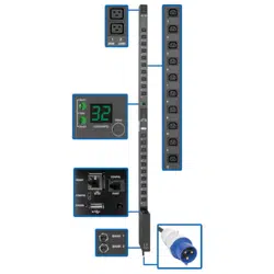
Features
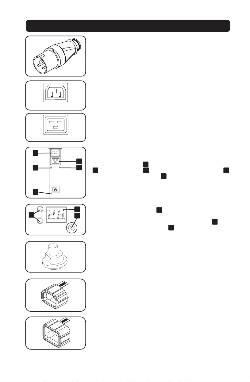
IEC 309 Blue 32A (2P+E) Input Plug
Outlets: During normal operation, the outlets distribute AC power
to connected equipment. When an outlet is live, the associated
LED illuminates.
Outlet LED: Each outlet LED illuminates when the associated
outlet is ready to distribute live AC power. The IEC-60320-C19
outlets are arranged in pairs, and there are 2 LEDs below each
pair. The LED to the left
A
is associated with the upper outlet
B
. The LED to the right
C
is associated with the lower outlet
D
. Other outlet types have an LED
E
directly below each outlet.
Digital Load Meter (Ammeter): The total connected equipment
load is displayed on the meter
A
in amperes. Models with
multiple outlet banks can also display the connected equipment
load for each outlet bank. Use the mode selection switch
B
to
display the total load (all bank LEDs
C
illuminated) or the load
for each outlet bank (corresponding bank LED illuminated).
Circuit Breaker: If the connected equipment load exceeds the
Maximum Load Rating of the PDU, the circuit breaker will trip.
Disconnect excess equipment and allow the breaker to cool
before depressing the plunger to reset the breaker. Models with
multiple outlet banks have a circuit breaker for each bank.
C14 Plug-Lock Inserts: Use the included C14 plug-lock inserts to
secure plugs to C13 receptacles. Attach the sleeve to the plug
making sure the pull tabs remain outside the plug and that the fit
is secure. To unplug equipment properly, use the pull tabs to
remove the plug and insert from the receptacle.
C20 Plug-Lock Inserts: Use the included C20 plug-lock inserts to
secure plugs to C19 receptacles. Attach the sleeve to the plug
making sure the pull tabs remain outside the plug and that the fit
is secure. To unplug equipment properly, use the pull tabs to
remove the plug and insert from the receptacle.
4
A
123
D
C
B
2 14 3
C
B
A
D
-
PLUG; IEC 309-2,
3-POL, 20A
250VAC
DO NOT SCALE DRAWING
WALTHER PLUG; IEC 309-2, 3-POL, 20A 250VAC
SHEET 1 OF 1
UNLESS OTHERWISE SPECIFIED:
SCALE: 1:1
WEIGHT:
REV
DWG. NO.
C
SIZE
TITLE:
NAME
DATE
COMMENTS:
Q.A.
MFG APPR.
ENG APPR.
CHECKED
DRAWN
-
FINISH
MATERIAL
INTERPRET GEOMETRIC
TOLERANCING PER:
DIMENSIONS ARE IN INCHES
TOLERANCES:
FRACTIONAL
ANGULAR: MACH
BEND
TWO PLACE DECIMAL
THREE PLACE DECIMAL
APPLICATION
USED ON
NEXT ASSY
PROPRIETARY AND CONFIDENTIAL
THE INFORMATION CONTAINED IN THIS
DRAWING IS THE SOLE PROPERTY OF
<INSERT COMPANY NAME HERE>. ANY
REPRODUCTION IN PART OR AS A WHOLE
WITHOUT THE WRITTEN PERMISSION OF
<INSERT COMPANY NAME HERE> IS
PROHIBITED.
IEC-60320-C13
IEC-60320-C19
1
1
3
3
2
2
A
E
D
C
B
C
A
B
Loading ...
Loading ...
Loading ...