
1
Owner’s Manual
Single-Phase Switched 0U
Power Distribution Unit
Model: PDUMV32HVNETLX
TrippLite.Eaton.com/support
Copyright © 2023 Tripp Lite. All rights reserved.
PROTECT YOUR INVESTMENT!
Register your product for quicker service
and ultimate peace of mind.
You could also win an
ISOBAR6ULTRA surge protector—
a $100 value!
www.tripplite.com/warranty
Important Safety Instructions 2
Installation 3
Features 5
Technical Support 6
Warranty and Product Registration 7
Español 8
Français 15
Русский 22
Deutsch 29

2
SAVE THESE INSTRUCTIONS
This manual contains instructions and warnings that should be
followed during the installation, operation, and storage of this product.
Failure to heed these warnings may affect your warranty.
Important Safety Instructions
• The PDU provides the convenience of multiple outlets, but DOES NOT provide surge or line
noise protection for connected equipment.
• The PDU is designed for indoor use only, in a controlled environment, away from excess
moisture, temperature extremes, conductive contaminants, dust or direct sunlight.
• Keep indoor ambient temperature between 0°C and 50°C (32°F and 122°F).
• The PDU must be installed by a qualified technician only.
• Do not attempt to mount the PDU to an insecure or unstable surface.
• Install in accordance with National Electrical Code standards. Be sure to use the proper
overcurrent protection for the installation, in accordance with the plug/equipment rating.
• Connect the PDU to an outlet that is in accordance with your local building codes and that is
adequately protected against excess currents, short circuits and earth faults.
• The electrical outlets supplying power to the equipment should be installed near the equipment
and easily accessible.
• Do not connect the PDU to an ungrounded outlet or to extension cords or adapters that
eliminate the connection to ground.
• Be sure to provide a local disconnect device on any models that are permanently installed
without a plug that is easily accessible.
• Never attempt to install electrical equipment during a thunderstorm.
• Individual equipment connected to the PDU should not draw more current than the individual
PDU’s outlet’s rating.
• The total load connected to the PDU must not exceed the maximum load rating for the PDU.
• Do not attempt to modify the PDU, input plugs or power cables.
• Do not drill into or attempt to open any part of the PDU housing. There are no user-serviceable
parts inside.
• Do not attempt to use the PDU if any part of it becomes damaged.
• Use of this equipment in life support applications where failure of this equipment can
reasonably be expected to cause the failure of the life support equipment or to significantly
affect its safety or effectiveness is not recommended.
3
Installation
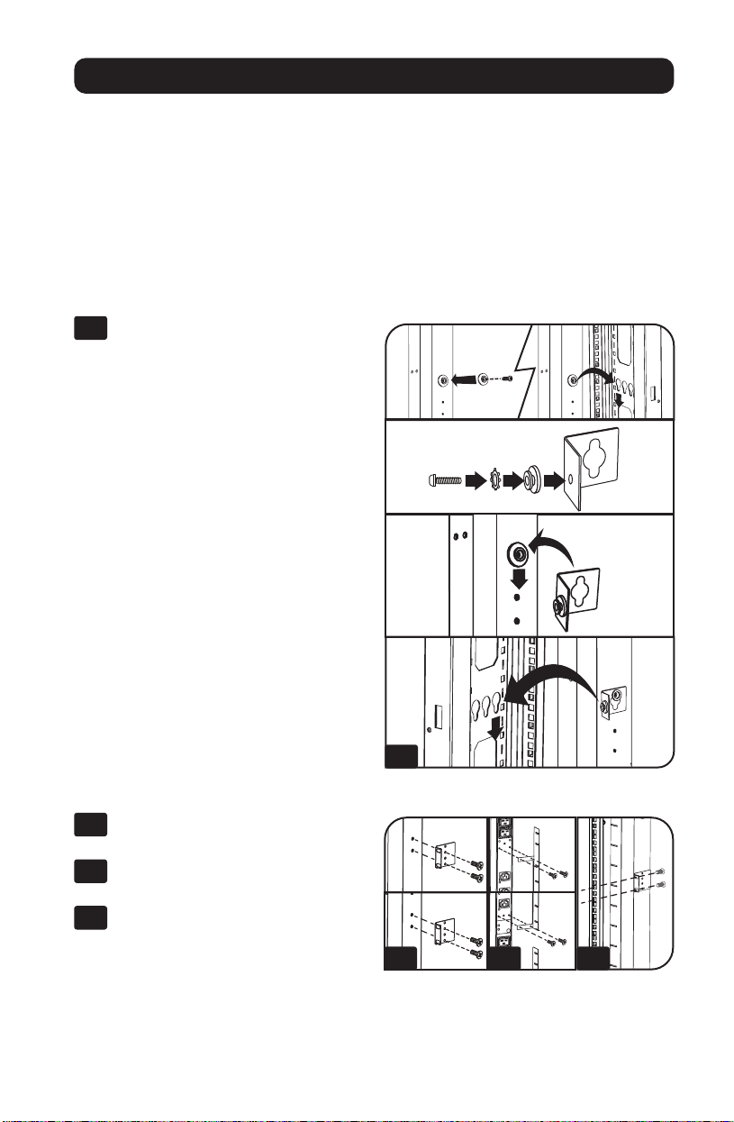
Mounting the PDU
Note: The illustrations may differ somewhat from your PDU model. Regardless of configuration, the user must
determine the fitness of hardware and procedures before mounting. The PDU and included hardware are
designed for common rack and rack enclosure types and may not be appropriate for all applications. Exact
mounting configurations may vary. Screws for attaching the mounting brackets and cord retention shelf to the
PDU are included. Use only the screws supplied by the manufacturer, or their exact equivalent.
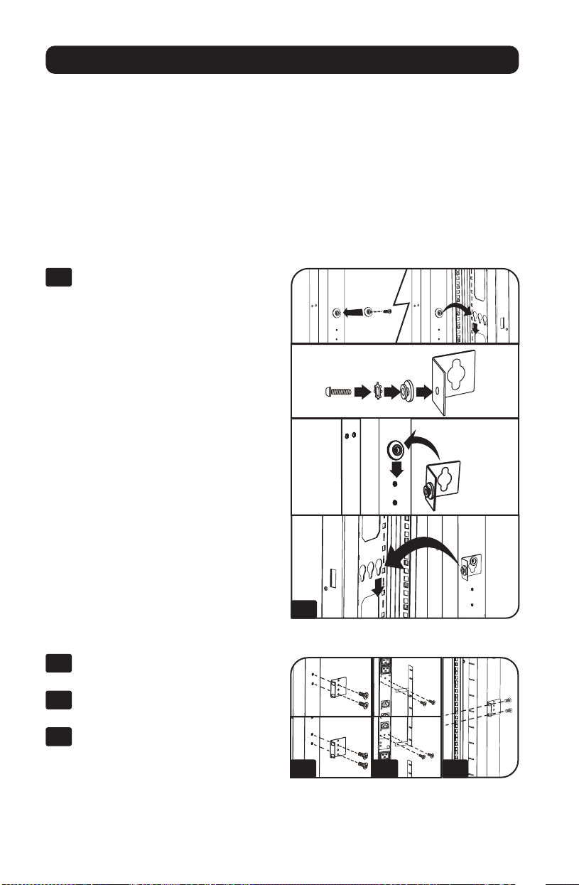
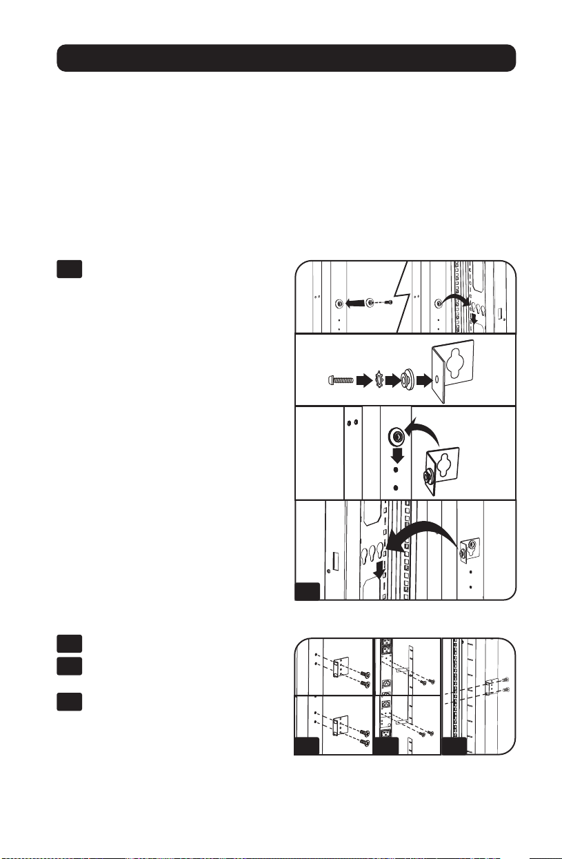
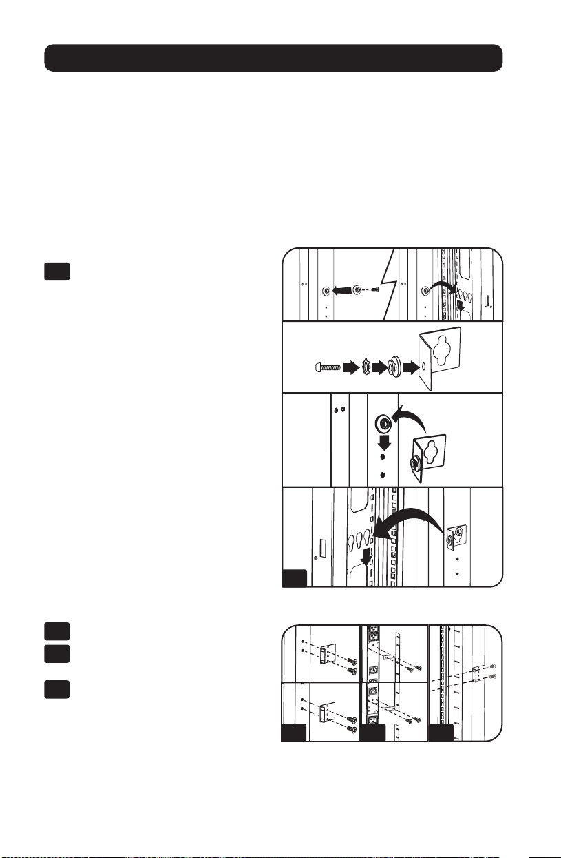
If installing the PDU in a rack that has button-mount slots, you only need to perform steps for
toolless mounting (step 1-1). If your rack does not have button-mount slots, proceed to
step 1-2.
Toolless Mounting
1-1
Attach the included mounting buttons
to the PDU. Position the PDU as desired
in the rack enclosure, align the buttons
with the rack mounting slots, and slide
the PDU into position.
Note: To install the PDU with its outlets
facing the rear of the rack, use the included
PDUMVROTATEBRKT accessory. This
V-shaped bracket provides a mounting button
on one leg of the V and a button-mount slot
on the other, effectively repositioning the
mounting buttons. See Features section for
image.
Regular Mounting
1-2
Attach the mounting brackets to the
PDU.
1-3
(Optional) Attach the cord retention
bracket(s) to the PDU.
1-4
Attach the PDU to a vertical rail in your
rack or rack enclosure. Use the
included mounting hardware to attach
the mounting brackets to the rail.
1-1
1-2 1-3 1-4
4
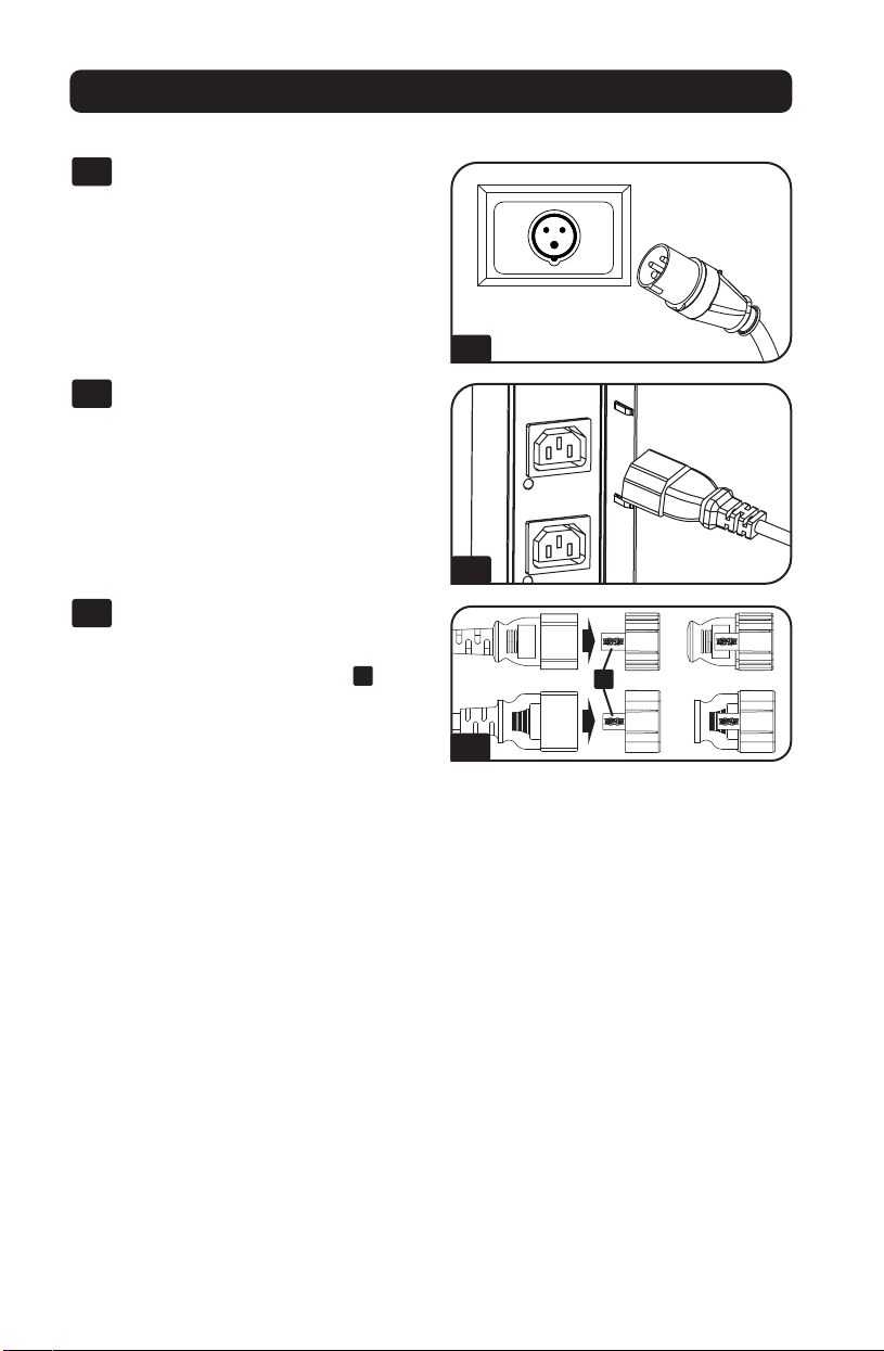
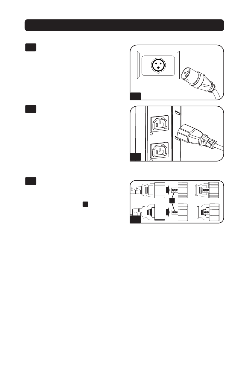
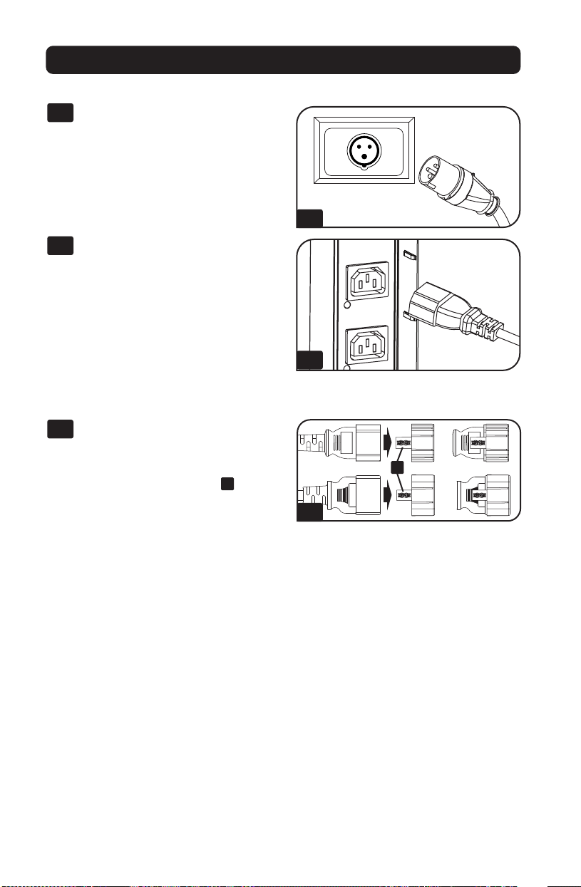
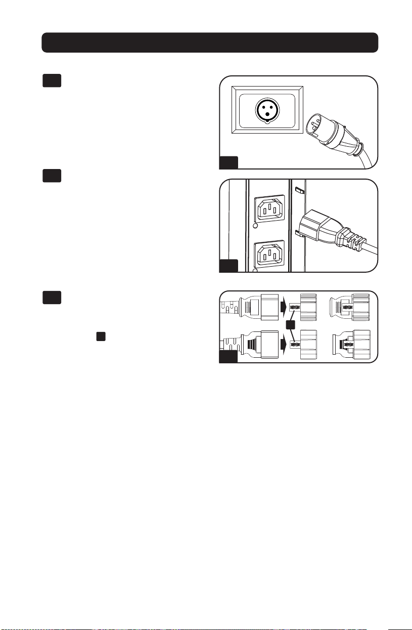
Connecting the PDU
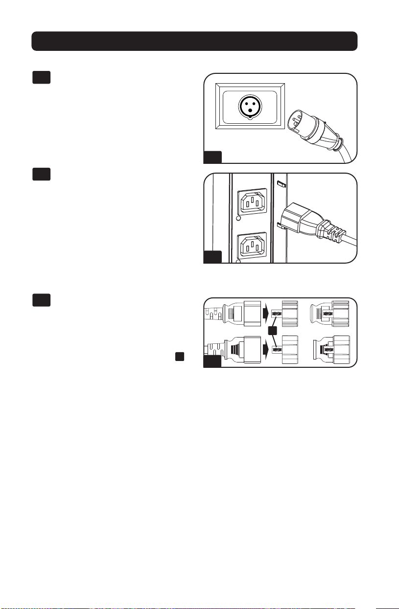
2-1
Connect the input plug to your facility’s
compatible AC power source.
2-2
Connect your equipment’s input plugs
to the appropriate outlets on the PDU.
On the Switched models, the LED near
each outlet illuminates when the outlet
is ready to distribute live AC power.
Note: It is recommended that you do not
connect a live load to the PDU. If the load
you intend to connect has an ON/OFF
switch, please turn the switch to OFF prior to
connection.
2-3
(Optional) Use the included C14 and
C20 plastic sleeves to secure plugs to
receptacles. Attach the sleeve to the
plug, making sure the pull tabs
A
remain outside the plug and that the fit
is secure. To unplug equipment
properly, use the pull tabs to remove
the plug and sleeve from the
receptacle.
Installation
Networking the PDU
For network configuration instructions, please refer to the WEBCARDLX owner’s manual
(PN 93358E) included with this product.
2-1
2-2
2-3
A
5
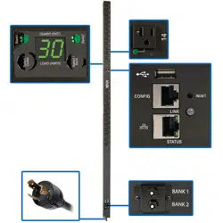
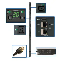
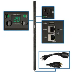
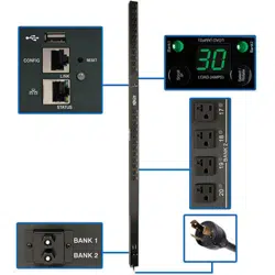
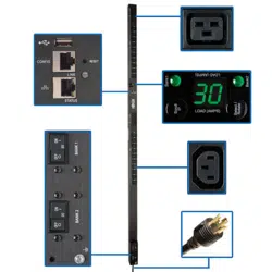
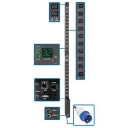
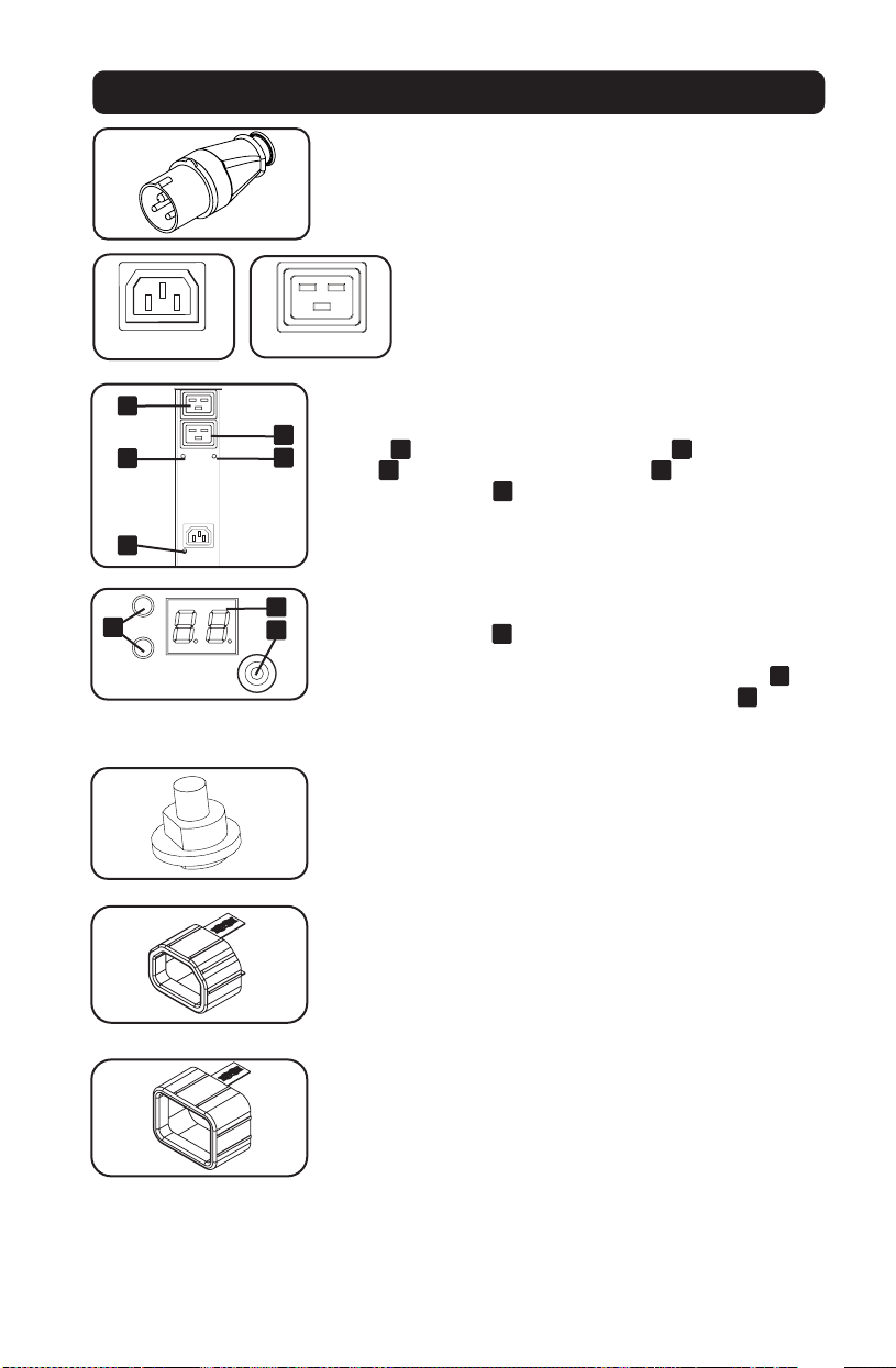
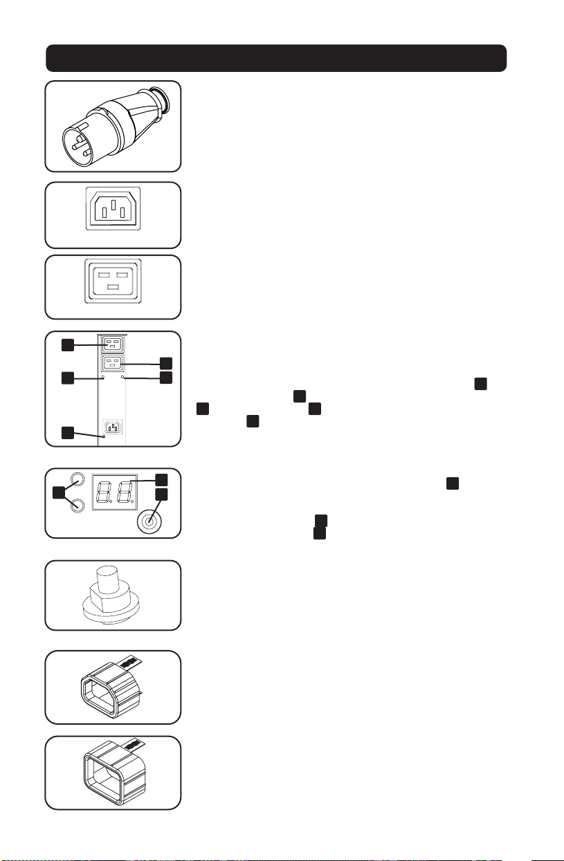
Features
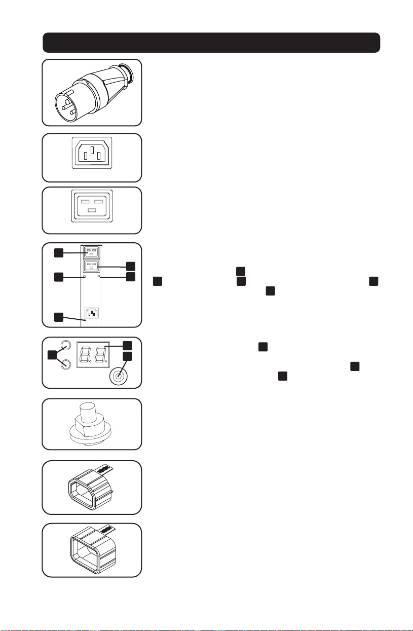
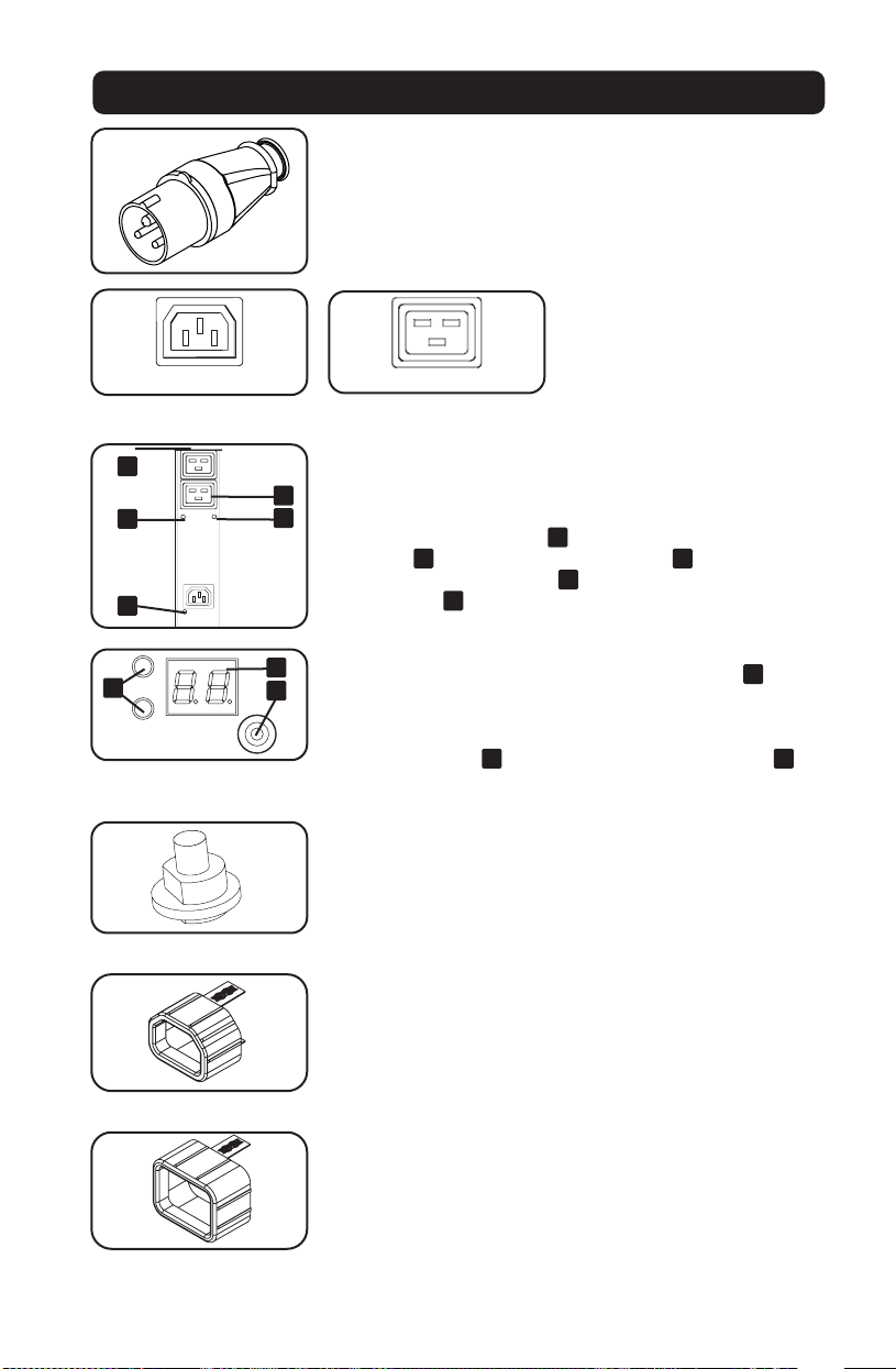
IEC 309 Blue 32A (2P+E) Input Plug
Outlets: During normal operation, the outlets distribute AC power
to connected equipment. When an outlet is live, the associated
LED illuminates.
Outlet LED: Each outlet LED illuminates when the associated
outlet is ready to distribute live AC power. The IEC-60320-C19
outlets are arranged in pairs, and there are 2 LEDs below each
pair. The LED to the left
A
is associated with the upper outlet
B
. The LED to the right
C
is associated with the lower outlet
D
. Other outlet types have an LED
E
directly below each outlet.
Digital Load Meter (Ammeter): The total connected equipment
load is displayed on the meter
A
in amperes. Models with
multiple outlet banks can also display the connected equipment
load for each outlet bank. Use the mode selection switch
B
to
display the total load (all bank LEDs
C
illuminated) or the load
for each outlet bank (corresponding bank LED illuminated).
Circuit Breaker: If the connected equipment load exceeds the
Maximum Load Rating of the PDU, the circuit breaker will trip.
Disconnect excess equipment and allow the breaker to cool
before depressing the plunger to reset the breaker. Models with
multiple outlet banks have a circuit breaker for each bank.
C14 Plug-Lock Inserts: Use the included C14 plug-lock inserts to
secure plugs to C13 receptacles. Attach the sleeve to the plug
making sure the pull tabs remain outside the plug and that the fit
is secure. To unplug equipment properly, use the pull tabs to
remove the plug and insert from the receptacle.
C20 Plug-Lock Inserts: Use the included C20 plug-lock inserts to
secure plugs to C19 receptacles. Attach the sleeve to the plug
making sure the pull tabs remain outside the plug and that the fit
is secure. To unplug equipment properly, use the pull tabs to
remove the plug and insert from the receptacle.
4
A
123
D
C
B
2 14 3
C
B
A
D
-
PLUG; IEC 309-2,
3-POL, 20A
250VAC
DO NOT SCALE DRAWING
WALTHER PLUG; IEC 309-2, 3-POL, 20A 250VAC
SHEET 1 OF 1
UNLESS OTHERWISE SPECIFIED:
SCALE: 1:1
WEIGHT:
REV
DWG. NO.
C
SIZE
TITLE:
NAME
DATE
COMMENTS:
Q.A.
MFG APPR.
ENG APPR.
CHECKED
DRAWN
-
FINISH
MATERIAL
INTERPRET GEOMETRIC
TOLERANCING PER:
DIMENSIONS ARE IN INCHES
TOLERANCES:
FRACTIONAL
ANGULAR: MACH
BEND
TWO PLACE DECIMAL
THREE PLACE DECIMAL
APPLICATION
USED ON
NEXT ASSY
PROPRIETARY AND CONFIDENTIAL
THE INFORMATION CONTAINED IN THIS
DRAWING IS THE SOLE PROPERTY OF
<INSERT COMPANY NAME HERE>. ANY
REPRODUCTION IN PART OR AS A WHOLE
WITHOUT THE WRITTEN PERMISSION OF
<INSERT COMPANY NAME HERE> IS
PROHIBITED.
IEC-60320-C13
IEC-60320-C19
1
1
3
3
2
2
A
E
D
C
B
C
A
B

6
www.tripplite.com/support
E-mail: [email protected]
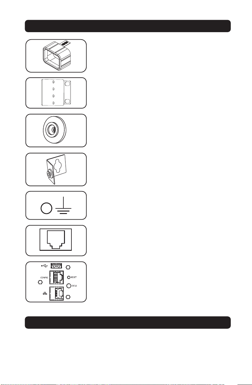
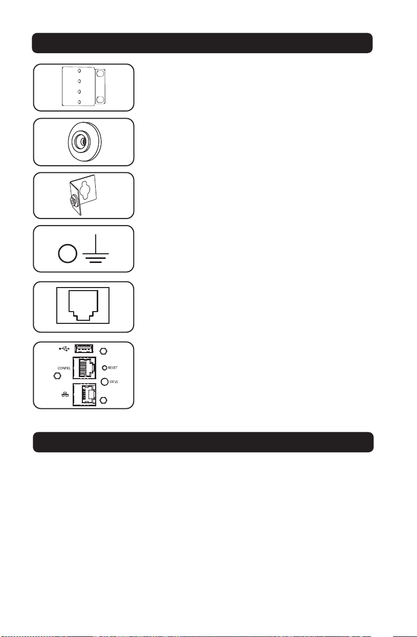
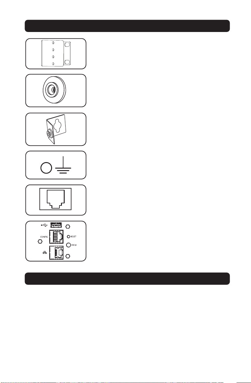
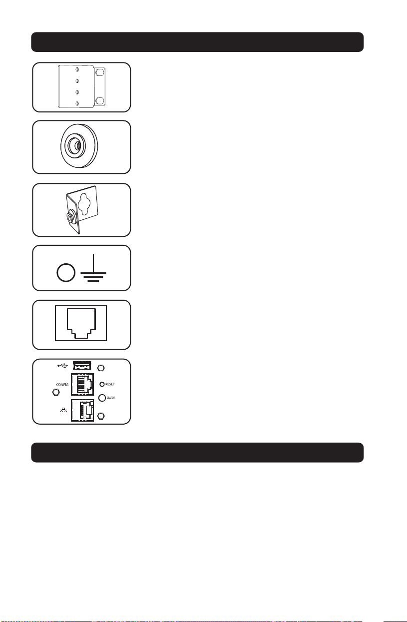
Mounting Brackets: Use these brackets to mount the PDU.
Mounting Buttons: Come pre-installed on the back side of the
PDU and are used for toolless mounting.
Note: Four additional mounting buttons are included for alternate rack
styles.
PDUMVROTATEBRKT Mounting Accessory: Use these V-shaped
brackets to mount the PDU with its outlets facing the rear of the
rack.
Ground Screw: Use this to connect any equipment that requires
a chassis ground.
Factory Port: The port is reserved for configuration by factory
authorized personnel only. Do not connect anything to the port.
LX Platform Interface: Allows you to operate this PDU as a
managed network device, accessible via SNMP network
management platform, web browser, SSH or Telnet.
Features
Technical Support

7
23-08-079 93-3732_revD
Warranty and Product Registration
Limited Warranty
Seller warrants this product, if used in accordance with all applicable instructions, to be free from original defects in material and
workmanship for a period of 2 years (except internal UPS system batteries outside USA and Canada, 1 year) from the date of initial
purchase. If the product should prove defective in material or workmanship within that period, Seller will repair or replace the
product, in its sole discretion. Service under this Warranty can only be obtained by your delivering or shipping the product (with all
shipping or delivery charges prepaid) to: Tripp Lite, 1111 W. 35th Street, Chicago, IL 60609 USA. Seller will pay return shipping
charges. Visit www.tripplite.com/support before sending any equipment back for repair.
THIS WARRANTY DOES NOT APPLY TO NORMAL WEAR OR TO DAMAGE RESULTING FROM ACCIDENT, MISUSE, ABUSE OR NEGLECT.
SELLER MAKES NO EXPRESS WARRANTIES OTHER THAN THE WARRANTY EXPRESSLY SET FORTH HEREIN. EXCEPT TO THE EXTENT
PROHIBITED BY APPLICABLE LAW, ALL IMPLIED WARRANTIES, INCLUDING ALL WARRANTIES OF MERCHANTABILITY OR FITNESS,
ARE LIMITED IN DURATION TO THE WARRANTY PERIOD SET FORTH ABOVE; AND THIS WARRANTY EXPRESSLY EXCLUDES ALL
INCIDENTAL AND CONSEQUENTIAL DAMAGES. (Some states do not allow limitations on how long an implied warranty lasts, and
some states do not allow the exclusion or limitation of incidental or consequential damages, so the above limitations or exclusions
may not apply to you. This Warranty gives you specific legal rights, and you may have other rights which vary from jurisdiction to
jurisdiction).
WARNING: The individual user should take care to determine prior to use whether this device is suitable, adequate or safe for the
use intended. Since individual applications are subject to great variation, the manufacturer makes no representation or warranty as
to the suitability or fitness of these devices for any specific application.
Product Registration
Visit www.tripplite.com/warranty today to register the warranty for your new Tripp Lite product. You'll be automatically entered into a
drawing for a chance to win a FREE Tripp Lite product!*
* No purchase necessary. Void where prohibited. Some restrictions apply. See website for details.
FCC Notice, Class A
This device complies with part 15 of the FCC Rules. Operation is subject to the following two conditions: (1) This device may not
cause harmful interference, and (2) this device must accept any interference received, including interference that may cause
undesired operation.
Note: This equipment has been tested and found to comply with the limits for a Class A digital device, pursuant to part 15 of the
FCC Rules. These limits are designed to provide reasonable protection against harmful interference when the equipment is
operated in a commercial environment. This equipment generates, uses, and can radiate radio frequency energy and, if not
installed and used in accordance with the instruction manual, may cause harmful interference to radio communications. Operation
of this equipment in a residential area is likely to cause harmful interference in which case the user will be required to correct the
interference at his own expense. The user must use shielded cables and connectors with this equipment. Any changes or
modifications to this equipment not expressly approved by Tripp Lite could void the user’s authority to operate this equipment.
Regulatory Compliance Identification Numbers
For the purpose of regulatory compliance certifications and identification, your Tripp Lite product has been assigned a unique series
number. The series number can be found on the product nameplate label, along with all required approval markings and
information. When requesting compliance information for this product, always refer to the series number. The series number should
not be confused with the marking name or model number of the product.
WEEE Compliance Information for Tripp Lite Customers and Recyclers (European Union)
Under the Waste Electrical and Electronic Equipment (WEEE) Directive and implementing regulations, when customers buy
new electrical and electronic equipment from Tripp Lite they are entitled to:
• Send old equipment for recycling on a one-for-one, like-for-like basis (this varies depending on the country)
• Send the new equipment back for recycling when this ultimately becomes waste
Tripp Lite has a policy of continuous improvement. Specifications are subject to change without notice.
TrippLite.Eaton.com/support

8
Manual del propietario
Unidad de Distribución de
Energía Monofásica
controlable de 0U
Modelo: PDUMV32HVNETLX
TrippLite.Eaton.com/support
Copyright © 2023 Tripp Lite. All rights reserved.
Instrucciones de seguridad importantes 9
Instalación 10
Características 12
Soporte técnico 13
Garantía 14
English 1
Français 15
Русский 22
Deutsch 29

9
GUARDE ESTAS INSTRUCCIONES
Este manual contiene instrucciones y advertencias que deben seguirse
durante la instalación, el funcionamiento y el almacenamiento de este
producto. Si no sigue estas instrucciones y advertencias puede afectar la
garantía del producto.
Instrucciones de seguridad importantes
• El PDU proporciona la conveniencia de múltiples tomacorrientes, pero NO proporciona
protección contra sobretensión o ruido en la línea para los equipos conectados.
• El PDU está diseñada solo para uso en interiores en un entorno controlado lejos de humedad
excesiva, temperaturas extremas, contaminantes conductivos, polvo o luz del sol directa.
• Mantiene la temperatura ambiente interior entre 0°C y 50°C.
• El PDU debe ser instalado solamente por un técnico calificado.
• No intente instalar el PDU en una superficie inestable o no segura.
• Instale de acuerdo con los reglamentos eléctricos locales. Asegúrese de usar para la
instalación la protección adecuada contra sobrecorriente, de acuerdo con la especificación de
la clavija o del equipo.
• Conecte el PDU a un tomacorriente que esté de acuerdo a los códigos locales de construcción
y que esté correctamente protegido contra corrientes excesivas, cortocircuitos y fallas de
conexión a tierra.
• Los tomacorrientes eléctricos que suministran energía al equipo deben instalarse próximos al
equipo y ser fácilmente accesibles.
• No conecte El PDU a un toma corriente que no esté a tierra o cables de extensión o
adaptadores que eliminen la conexión a tierra.
• Asegúrese de proporcionar un dispositivo local de desconexión, que sea fácilmente accesible,
en cualquier modelo que esté instalado permanentemente sin una clavija.
• Nunca intente instalar equipos eléctricos durante una tormenta eléctrica.
• El equipo individual conectado al PDU no debe consumir más corriente que la de la
especificación de cada tomacorriente individual del PDU.
• La carga total conectada al PDU no debe exceder la capacidad de carga máxima del PDU.
• No intente modificar el PDU, las clavijas de entrada o los cables de alimentación.
• No perfore ni intente abrir ninguna parte del gabinete del PDU. No tiene partes a las que el
usuario pueda dar servicio.
• No intente usar el PDU si se daña cualquier parte.
• No se recomienda el uso de este equipo en aplicaciones de soporte de vida en donde la falla
de este equipo pueda consecuentemente causar la falla del equipo de soporte de vida o
afectar significativamente su seguridad o efectividad.
10
Instalación
Montaje de la PDU
Nota: Las ilustraciones pueden diferir del modelo de la PDU. Independientemente de la configuración, el
usuario debe determinar la aptitud de las herramientas y los pasos antes de montarlo. La PDU y las
herramientas incluidas están diseñadas para racks comunes y racks y pueden no ser adecuadas para todas
las aplicaciones. La configuración exacta puede variar. Se incluyen tornillos para unir los soportes de montaje y
el estante de retención del cable a la PDU. Utilice sólo los tornillos suministrados por el fabricante, o su
equivalente exacto (#6-32, ¼ pulg. cabeza plana).
Si instala un PDU en un rack que tenga ranuras de instalación de botón, sólo necesita realizar los
pasos para la instalación sin herramientas (paso 1-1) Si su rack no tiene ranuras de instalación
de botón, proceda a paso 1-2.
Instalación sin Herramienta
1-1
Fije los botones de instalación incluidos
al PDU. Posicione el PDU como desee
en el gabinete de rack, alinee los
botones con las ranuras de instalación
del rack y deslice el PDU a su posición.
Nota: Para instalar el PDU con sus
tomacorrientes orientado hacia la parte
posterior del rack, use el accesorio
PDUMVROTATEBRKT incluido. Está ménsula
en forma de V proporciona un botón de
instalación en una pata de la V y una ranura
de instalación de botón en la otra,
reposicionando efectivamente los botones de
instalación. Para ver una imagen, consulte la
sección de Características.
Instalación Normal
1-2
Fije las ménsulas de instalación al
PDU.
1-3
(Opcional) Fije el(los) soporte(s) de
sujeción del cable al PDU.
1-4
Fije el PDU a un riel vertical en su rack
o gabinete. Use las partes para
instalación incluidas, para acoplar los
soportes de instalación al riel.
1-1
1-2 1-3 1-4
11
Conexión de la PDU
2-1
Conecte el enchufe de entrada a la
fuente de alimentación de CA
compatible de la instalación.
2-2
Conecte los enchufes de entrada del
equipo a los tomacorrientes adecuados
de la PDU. En modelos con
interruptores, el LED junto a cada
tomacorriente se ilumina cuando el
tomacorriente está listo para distribuir
alimentación de CA.
Nota: Se recomienda no conectar una carga
viva a la PDU. Si la carga que intenta
conectar tiene un interruptor de encendido/
apagado, coloque por favor el interruptor en
la posición de apagado antes de la conexión.
2-3
(Opcional) Use los manguitos plásticos
C14 y C20 incluidos para sujetar las
clavijas a los contactos. Instale el
manguito a la clavija, asegurando que
las lengüetas de tiro
A
permanezcan
fuera de la clavija y que la sujeción
esté segura. Para desenchufar
correctamente el equipo, use las
lengüetas de tiro para retirar la clavija
y manguito del contacto.
Instalación
Conexión a Red del PDU
Para obtener instrucciones de configuración de red, consulte el manual del propietario de
WEBCARDLX (PN 93358E) incluido con este producto.
2-1
2-2
2-3
A
12
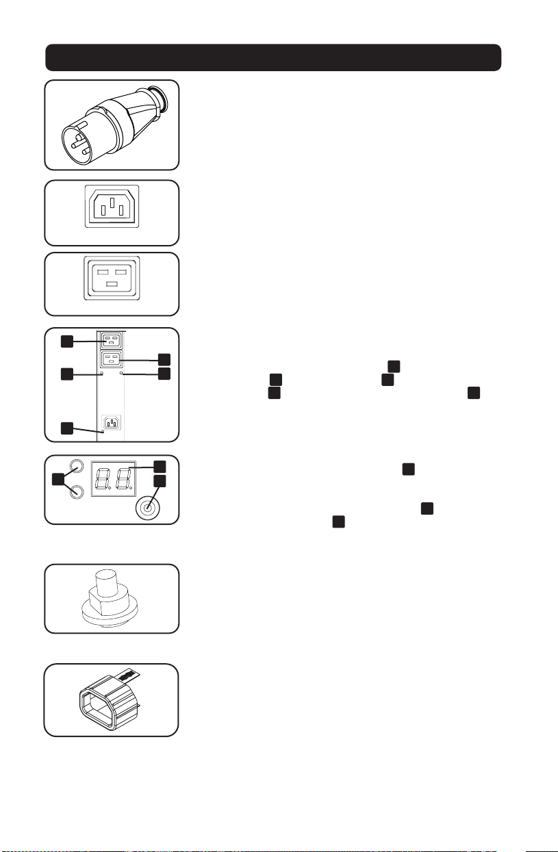
Características
Clavija de Entrada IEC 309 32A Azul (2P+T)
Salidas: Durante la operación normal, las salidas distribuyen
energía CA al equipo conectado. Cuando la salida está viva, el
LED asociado se enciende.
LED de las Salidas: Cada LED de las salidas se enciende cuando
la salida asociada está lista para distribuir energía CA viva. Las
salidas IEC-60320-C19 están agrupadas en pares y hay 2 LEDs
debajo de cada par. El LED a la izquierda
A
está asociado a la
salida de arriba
B
. El LED a al derecha
C
está asociado con la
salida de abajo
D
. Otros tipos de de salida tienen un LED
E
directamente abajo de cada salida.
Medidor Digital de Carga (Amperímetro): La carga total del
equipo conectado se muestra en el medidor
A
in amperes.
Modelos con múltiples bancos de salidas también pueden
mostrar la carga del equipo conectado por cada banco de
salidas. Use el interruptor de selección de modo
B
para mostrar
la carga total (todos los LEDs
C
del banco encendidos) o la
carga total por cada banco de salidas (El LED del banco
correspondiente encendido).
Interruptor de Circuitos: Si la carga del equipo conectado
excede el Nivel de Carga Máxima Nominal del PDU, el interruptor
de circuitos se disparará. Desconecte el exceso de equipo y
permita al interruptor de circuitos enfriarse antes de presionar el
botón para restaurar el interruptor de circuitos. Modelos con
múltiples bancos de salidas tienen un interruptor de circuitos por
cada banco.
Insertos Plug-Lock C14: Use los insertos Plug-Lock C14
incluidos para sujetar las clavijas a los tomacorrientes C13.
Instale el manguito a la clavija, asegurando que las lengüetas de
tiro permanezcan fuera de la clavija y que la sujeción esté
segura. Para desenchufar correctamente el equipo, use las
lengüetas de tiro para retirar la clavija e inserto del contacto.
4
A
123
D
C
B
2 14 3
C
B
A
D
-
PLUG; IEC 309-2,
3-POL, 20A
250VAC
DO NOT SCALE DRAWING
WALTHER PLUG; IEC 309-2, 3-POL, 20A 250VAC
SHEET 1 OF 1
UNLESS OTHERWISE SPECIFIED:
SCALE: 1:1
WEIGHT:
REV
DWG. NO.
C
SIZE
TITLE:
NAME
DATE
COMMENTS:
Q.A.
MFG APPR.
ENG APPR.
CHECKED
DRAWN
-
FINISH
MATERIAL
INTERPRET GEOMETRIC
TOLERANCING PER:
DIMENSIONS ARE IN INCHES
TOLERANCES:
FRACTIONAL
ANGULAR: MACH
BEND
TWO PLACE DECIMAL
THREE PLACE DECIMAL
APPLICATION
USED ON
NEXT ASSY
PROPRIETARY AND CONFIDENTIAL
THE INFORMATION CONTAINED IN THIS
DRAWING IS THE SOLE PROPERTY OF
<INSERT COMPANY NAME HERE>. ANY
REPRODUCTION IN PART OR AS A WHOLE
WITHOUT THE WRITTEN PERMISSION OF
<INSERT COMPANY NAME HERE> IS
PROHIBITED.
IEC-60320-C13
IEC-60320-C19
1
1
3
3
2
2
A
E
D
C
B
C
A
B
13
www.tripplite.com/support
Correo Electrónico: [email protected]
Insertos Plug-Lock C20: Use los insertos Plug-Lock C20
incluidos para sujetar las clavijas a los tomacorrientes C19.
Instale el manguito a la clavija, asegurando que las lengüetas de
tiro permanezcan fuera de la clavija y que la sujeción esté
segura. Para desenchufar correctamente el equipo, use las
lengüetas de tiro para retirar la clavija e inserto del contacto.
Soportes de Montaje Cortos: Use estos soportes para montar el
PDU.
Botones de Instalación: Vienen preinstalados en el lado
posterior del PDU y se usan para instalación sin herramienta.
Nota: Se incluyen cuatro botones de instalación adicionales para estilos
de rack alternativos.
Accesorio de Instalación PDUMVROTATEBRKT: Use estos
soportes en forma de V para instalar el PDU con sus
tomacorrientes orientados hacia el rack.
Tornillo de Conexión a Tierra: Utilícelo para conectar los
equipos que requieren conexión a tierra del chasís.
Puerto de fábrica: Este puerto está reservado para la
configuración, la cual deberá realizar solamente el personal
autorizado por la fábrica. No conecte nada al puerto.
Interfaz de Plataforma LX Le permite operar este PDU como un
dispositivo de red, accesible mediante una plataforma de
administración de red SNMP, navegador de red, SSH o Telnet.
Características
Soporte Técnico

14
Garantía
GARANTÍA LIMITADA
El vendedor garantiza este producto, si se usa de acuerdo con todas las instrucciones aplicables, de que está libre de defectos en
material y mano de obra por un período de 2 años (excepto baterías internas del sistema UPS fuera de EE.UU. y Canadá: 1 año)
desde la fecha de compra inicial. Si el producto resulta defectuoso en material o mano de obra dentro de ese período, el vendedor
reparará o reemplazará el producto a su entera discreción. El servicio bajo esta garantía sólo puede obtenerse enviando o
embarcando el producto (con todos los cargos de envío o embarque prepagados) a: Tripp Lite, 1111 W. 35th Street, Chicago, IL
60609 EE UU. El vendedor reembolsará los cargos de embarque. Llame al Servicio al Usuario de Tripp Lite al 773.869.1234 antes
de regresar cualquier equipo para reparación.
ESTA GARANTÍA NO SE APLICA AL DESGASTE NORMAL O A LOS DAÑOS QUE RESULTEN DE ACCIDENTES, USO INCORRECTO, USO
INDEBIDO O NEGLIGENCIA. EL VENDEDOR NO OTORGA GARANTÍAS EXPRESAS DISTINTAS DE LA ESTIPULADA EN EL PRESENTE.
SALVO EN LA MEDIDA EN QUE LO PROHÍBAN LAS LEYES APLICABLES, TODAS LAS GARANTÍAS IMPLÍCITAS, INCLUYENDO TODAS LAS
GARANTÍAS DE COMERCIALIZACIÓN O IDONEIDAD, ESTÁN LIMITADAS EN DURACIÓN AL PERÍODO DE GARANTÍA ESTABLECIDO;
ASIMISMO, ESTA GARANTÍA EXCLUYE EXPRESAMENTE TODOS LOS DAÑOS INCIDENTALES E INDIRECTOS. (Algunos estados no
permiten limitaciones en cuanto dura una garantía y algunos estados no permiten la exclusión de limitación de daños incidentales
o consecuenciales, de modo que las limitaciones anteriores pueden no aplicar para usted. Esta garantía le otorga derechos legales
específicos y usted puede tener otros derechos que pueden variar de una jurisdicción a otra).
ADVERTENCIA: Antes de usarlo, cada usuario debe debe tener cuidado al determinar si este dispositivo es adecuado o seguro para
el uso previsto. Ya que las aplicaciones individuales están sujetas a gran variación, el fabricante no garantiza la adecuación de
estos dispositivos para alguna aplicación específica.
Números de Identificación de Conformidad Regulatoria
Para el propósito de certificaciones e identificación de conformidad con las normas, su producto Tripp Lite ha recibido un número
de serie exclusivo. El número de serie puede encontrarse en la etiqueta de placa de identificación, junto con todas las marcas e
información requeridas de aprobación. Al solicitar información de conformidad para este producto, refiera siempre el número de
serie. El número de serie no debe confundirse con el nombre de la marca o el número de modelo del producto.
Información de sobre Cumplimiento de la WEEE para Clientes de Tripp Lite y Recicladores
(Unión Europea)
Según la Directiva de Residuos de Aparatos Eléctricos y Electrónicos (Waste Electrical and Electronic Equipment, WEEE) y
sus reglamentos, cuando los clientes compran nuevos equipos eléctricos y electrónicos a Tripp Lite, tienen derecho a:
• Enviar equipos antiguos para reciclaje según una base de uno por uno, entre productos similares (esto varía
dependiendo del país)
• Enviar el equipo nuevo de vuelta para reciclaje cuando este se convierta finalmente en desecho
Tripp Lite tiene una política de mejora continua. Las especificaciones están sujetas a cambio sin previo aviso.
23-08-079 93-3732_revD
TrippLite.Eaton.com/support

15
Manuel de l'utilisateur
Unité de distribution
électrique commutée
monophasée 0U
Modèle : PDUMV32HVNETLX
TrippLite.Eaton.com/support
Copyright © 2023 Tripp Lite. All rights reserved.
Consignes de sécurité importantes 16
Installation 17
Caractéristiques 19
Soutien technique 20
Garantie 21
English 1
Español 8
Русский 22
Deutsch 29

16
CONSERVEZ CES INSTRUCTIONS
Ce manuel contient des instructions et des avertissements qui doivent être
respectés pendant l'installation, l'utilisation et l'entreposage de ce produit.
Le non-respect de ces instructions et de ces avertissements annulera la
garantie du produit.
Consignes de sécurité importantes
• La PDU fournit des prises multiples pratiques, mais elle ne FOURNIT PAS de protection contre
les surtensions ou les bruits de ligne pour l'équipement connecté.
• La PDU est conçue pour être utilisée à l'intérieur uniquement, dans un environnement contrôlé,
à l'écart de l'excès d'humidité, des températures extrêmes, des contaminants conducteurs, de
la poussière et de la lumière directe du soleil.
• Maintenir la température intérieure ambiante entre 0 °C et 50 °C.
• La PDU doit être installée par un technicien qualifié seulement.
• Ne pas tenter de monter la PDU sur une surface précaire ou instable.
• Installer conformément aux codes locaux de l'électricité. S'assurer d'utiliser la bonne
protection contre les surintensités pour l'installation, conformément aux valeurs nominales de
la fiche et de l'équipement.
• Branchez la PDU à une prise de courant à une prise de courant qui est conforme aux codes de
bâtiment locaux et qui est dûment protégée contre les courants excessifs, les courts-circuits et
les défauts à la terre.
• Les prises électriques qui alimentent l'équipement doivent être installées à proximité de
l'équipement et être facilement accessibles.
• Ne pas connecter la PDU dans une prise non mise à la masse ou des rallonges électriques ou
des adaptateurs qui éliminent la connexion à la masse.
• S'assurer de fournir un dispositif de déconnexion local pour tous les modèles qui sont installés
en permanence sans fiche facilement accessible.
• Ne jamais essayer d'installer un équipement électrique pendant un orage.
• L'équipement individuel connecté à la PDU ne doit pas excéder la charge nominale des prises
individuelles de la PDU.
• La charge totale connectée à la PDU ne doit pas excéder la charge nominale maximum pour la
PDU.
• Ne pas tenter de modifier la PDU, y compris les fiches d'entrée et les câbles d'alimentation.
• Ne pas percer ou tenter d'ouvrir une quelconque partie du boîtier de la PDU. Il n'existe aucune
pièce réparable par l'utilisateur à l'intérieur.
• Ne pas tenter d'utiliser la PDU si une de ses pièces est endommagée.
• Il n'est pas recommandé d'utiliser cet équipement dans les applications de soutien vital où une
panne de cet équipement serait susceptible de causer une panne de l'équipement de soutien
vital ou d'affecter sérieusement sa sécurité ou son efficacité.
17
Installation
Montage de la PDU
Remarque : Les illustrations peuvent être différentes de celles de votre modèle de PDU. Sans tenir compte de
la configuration, l’utilisateur doit déterminer la compatibilité de la quincaillerie et les procédures avant
d’effectuer l’installation. La PDU et la quincaillerie incluse sont conçues pour des types de bâti et boîtier
courants et peuvent ne pas convenir à toutes les applications. Les configurations de montage exactes peuvent
varier. Les vis pour fixer les supports de fixation et la tablette de retenue des cordons à la PDU sont incluses.
N’utiliser que les vis fournies par le fabricant ou leur équivalent exact (#6-32, ¼ po, à tête plate).
Si vous installez le PDU dans un montage en baie qui a des fentes de montage pour boutons, il
vous suffit d’exécuter les étapes de montage sans outil (étape 1-1). Si votre montage en baie ne
dispose pas de fentes de montage pour boutons, passer à l’étape 1-2.
Montage sans outil
1-1
Fixer au PDU les boutons de montage
inclus. Placer le PDU comme souhaité
dans le montage en baie, aligner les
boutons avec les fentes de montage du
montage en baie et glisser le PDU en
position.
Remarque : Pour installer le PDU avec ses
sorties face à l’arrière du montage en baie,
utiliser l’accessoire PDUMVROTATEBRKT
inclus. Ce support en forme de V, comporte
un bouton de montage sur une jambe du V
et une fente de montage pour bouton sur
l’autre, repositionnant efficacement les
boutons de montage. Voir la section des
caractéristiques pour l’illustration.
Montage régulier
1-2
Fixer au PDU les supports de montage.
1-3
(Optionnel) Fixer le support de
rétention de cordon au PDU.
1-4
Fixer le PDU à un rail vertical dans
votre montage en baie ou en armoire.
Utiliser le matériel de montage fourni
pour fixer les supports de montage au
rail.
1-1
1-2 1-3 1-4
18
Connexion de la PDU
2-1
Brancher la fiche d’entrée à une prise
de courant CA compatible.
2-2
Connectez les fiches d’entrée de votre
équipement à aux prises appropriées
sur la PDU. Sur les modèles
commandés par interrupteur, le témoin
DEL près de chaque prise s’allume
quand celle-ci est prête à distribuer du
courant CA.
Remarque : Il est conseillé que vous ne
connectiez pas de charge dynamique à la
PDU. Si la charge que vous prévoyez
connecter est équipée d’un interrupteur ON/
OFF, veuillez mettre l’interrupteur en position
OFF avant la connexion.
2-3
(Optionnel)
Utiliser les manchons en
plastique C14 et C20 inclus pour
retenir les fiches aux prises. Fixer le
manchon à la fiche en s'assurant que
les languettes de préhension
A
demeurent à l'extérieur de la fiche et
qu'il repose solidement en place. Pour
débrancher correctement l'équipement,
utiliser les languettes de préhension
pour retirer la fiche et le manchon de la
prise de courant.
Installation
Fonctionnement en réseau de la PDU
Pour des instructions sur la configuration en réseau, veuillez vous référer au manuel de
l'utilisateur de la WEBCARDLX (n° de pièce 93358E) inclus avec ce produit.
2-1
2-2
2-3
A
19
Caractéristiques
Fiche d'entrée IEC 309 de 32 A bleu (2P+T)
Prises : Lors d'un fonctionnement normal, les prises
distribuent du courant CA à l'équipement connecté.
Quand une prise est sous tension, la DEL
correspondante s'allume.
DEL de prise : Chaque prise dispose d'une DEL verte qui s'allume
quand la prise reçoit du courant CA. Les prises CEI-60320-C19
sont couplées et il y a 2 DEL sous chaque paire. La DEL de
gauche
A
est associée à la prise supérieure
B
. La DEL de
droite
C
est associée à la prise inférieure
D
. Les autres types
de prise ont une DEL
E
directement sous chaque prise.
Compteur numérique de charge (Ampèremètre) : La charge
totale de l'équipement connecté est affichée en ampères au
compteur numérique
A
. Les modèles avec plusieurs barres de
prise peuvent également afficher la charge de l'équipement
connecté pour chaque barre. Utiliser le sélecteur de mode
B
pour afficher la charge totale (toutes les DEL de barre
C
allumées) ou la charge pour chaque barre (correspondant à la
DEL de barre allumée).
Disjoncteur (certains modèles) : Si la charge de l'équipement
connecté dépasse la charge nominale maximale de la PDU, le
disjoncteur se déclenchera. Déconnecter l'équipement en trop et
laisser le disjoncteur refroidir avant de le réenclencher. Les
modèles avec plusieurs barres de prise ont un disjoncteur pour
chaque barre.
Inserts enfichables-verrouillables C14 : Utiliser les inserts
enfichables-verrouillables C14 inclus pour retenir les fiches aux
prises de courant C13. Fixer le manchon à la fiche en s'assurant
que les languettes de préhension demeurent à l'extérieur de la
fiche et qu'il repose solidement en place. Pour débrancher
correctement l'équipement, utiliser les languettes de préhension
pour retirer la fiche et l'insert de la prise de courant.
Inserts enfichables-verrouillables C20 : Utiliser les inserts
enfichables-verrouillables C20 inclus pour retenir les fiches aux
prises de courant C19. Fixer le manchon à la fiche en s'assurant
que les languettes de préhension demeurent à l'extérieur de la
fiche et qu'il repose solidement en place. Pour débrancher
correctement l'équipement, utiliser les languettes de préhension
pour retirer la fiche et l'insert de la prise de courant.
4
A
123
D
C
B
2 14 3
C
B
A
D
-
PLUG; IEC 309-2,
3-POL, 20A
250VAC
DO NOT SCALE DRAWING
WALTHER PLUG; IEC 309-2, 3-POL, 20A 250VAC
SHEET 1 OF 1
UNLESS OTHERWISE SPECIFIED:
SCALE: 1:1
WEIGHT:
REV
DWG. NO.
C
SIZE
TITLE:
NAME
DATE
COMMENTS:
Q.A.
MFG APPR.
ENG APPR.
CHECKED
DRAWN
-
FINISH
MATERIAL
INTERPRET GEOMETRIC
TOLERANCING PER:
DIMENSIONS ARE IN INCHES
TOLERANCES:
FRACTIONAL
ANGULAR: MACH
BEND
TWO PLACE DECIMAL
THREE PLACE DECIMAL
APPLICATION
USED ON
NEXT ASSY
PROPRIETARY AND CONFIDENTIAL
THE INFORMATION CONTAINED IN THIS
DRAWING IS THE SOLE PROPERTY OF
<INSERT COMPANY NAME HERE>. ANY
REPRODUCTION IN PART OR AS A WHOLE
WITHOUT THE WRITTEN PERMISSION OF
<INSERT COMPANY NAME HERE> IS
PROHIBITED.
IEC-60320-C13
IEC-60320-C19
1
1
3
3
2
2
A
E
D
C
B
C
A
B
20
www.tripplite.com/support
Adresse électronique : [email protected]
Supports de fixation courts : Utilisez ces supports pour fixer
l'unité de distribution.
Boutons de montage : Sont préinstallés sur le côté arrière du
PDU et sont utilisés pour le montage sans outil.
Remarque : Quatre autres boutons de montage sont inclus pour les styles
de montage en baie de rechange.
Accessoire de montage du PDUMVROTATEBRKT : Utiliser ces
supports en forme de V pour monter le PDU avec ses sorties
face à l’arrière du montage en baie.
Vis de borne de terre : Utiliser cette option pour connecter
n’importe quel équipement qui nécessite une mise à la terre du
châssis.
Port d’usine : Ce port est réservé pour la configuration en usine
uniquement par du personnel autorisé. Ne rien connecter à ce
port.
LX Platform Interface : Permet d'utiliser cette PDU comme un
dispositif géré par le réseau, accessible via la plateforme de
gestion de réseau SNMP, un navigateur Web, SSH ou Telnet.
Caractéristiques
Soutien technique

21
Garantie
GARANTIE LIMITÉE
Le vendeur garantit que ce produit, s'il est utilisé conformément à toutes les instructions applicables, est exempt de tous défauts de matière et de fabrication
pour une période de 2 ans (sauf les batteries de l'onduleur à l’extérieur des États-Unis et au Canada, 1 an) à partir de la date d'achat initiale. Si le produit
s'avère défectueux en raison d'un vice de matière ou de fabrication au cours de cette période, le vendeur s'engage à réparer ou remplacer le produit, à sa
seule discrétion. Le service sous cette garantie ne peut être obtenue qu'en livrant ou en expédiant le produit (avec tous les frais d'expédition ou de livraison
prépayés) à : Tripp Lite, 1111 W. 35th Street, Chicago, IL 60609 États-Unis. Le vendeur paiera les frais d'expédition de retour. Appeler le service à la clientèle
de Tripp Lite au 773 869-1234 avant d'envoyer de l'équipement pour réparation.
CETTE GARANTIE NE S'APPLIQUE PAS À L'USURE NORMALE OU AUX DOMMAGES RÉSULTANT D'UNE MAUVAISE UTILISATION, D'UN ABUS OU D'UNE
NÉGLIGENCE. LE VENDEUR NE DONNE AUCUNE GARANTIE EXPRESSE AUTRE QUE LA GARANTIE EXPRESSÉMENT DÉCRITE DANS LE PRÉSENT DOCUMENT.
SAUF DANS LA MESURE INTERDITE PAR LA LOI APPLICABLE, TOUTE GARANTIE IMPLICITE, Y COMPRIS TOUTES LES GARANTIES DE QUALITÉ MARCHANDE OU
D'ADAPTATION, SONT LIMITÉES À LA PÉRIODE DE GARANTIE CI-DESSUS ET CETTE GARANTIE EXCLUT EXPRESSÉMENT TOUS DOMMAGES DIRECTS ET
INDIRECTS. (Certains États ne permettent pas de limitations sur la durée d'une garantie implicite, et certains états ne permettent pas l'exclusion ou la
limitation des dommages fortuits ou consécutifs, de sorte que les limitations ou exclusions susmentionnées peuvent ne pas s'appliquer à vous. Cette garantie
vous donne des droits légaux spécifiques, et vous pouvez avoir d'autres droits qui varient selon le territoire).
AVERTISSEMENT : L'utilisateur individuel doit prendre soin de déterminer avant l'utilisation si cet appareil est approprié, adéquat et sûr pour l'usage prévu.
Puisque les utilisations individuelles sont sujettes à des variations importantes, le fabricant ne fait aucune déclaration ou garantie quant à l'aptitude ou
l'adaptation de ces dispositifs pour une application spécifique.
Numéros d'identification à la conformité réglementaire
À des fins de certification de conformité réglementaire et d'identification, votre produit Tripp Lite, un numéro de série unique lui a été attribué. Le numéro de
série ainsi que toutes les marques d'homologation et les renseignements requis se trouvent sur la plaque signalétique du produit. Lorsque vous demandez
des renseignements concernant la conformité de ce produit, reportez-vous toujours au numéro de série. Le numéro de série ne doit pas être confondu avec le
nom de la marque ou le numéro de modèle du produit.
L’information de conformité WEEE pour les clients de Tripp Lite et recycleurs (Union européenne)
Sous les directives et règlements de déchet d’équipements électrique et électronique (Waste Electrical and Electronic Equipment, WEEE), lorsque
les clients achètent le matériel électrique et électronique neuf de Tripp Lite ils sont autorisés à :
• Envoyer le vieux matériel pour le recyclage sur une base de un-contre-un et en nature (ceci varie selon le pays)
• Renvoyer le matériel neuf pour recyclage quand ceci devient éventuellement un rebut
La politique de Tripp Lite en est une d'amélioration continue. Les caractéristiques techniques sont modifiables sans préavis.
23-08-079 93-3732_revD
TrippLite.Eaton.com/support

22
Руководство пользователя
Однофазный управляемый блок
распределения питания
вертикального монтажа (0U)
Модель: PDUMV32HVNETLX
TrippLite.Eaton.com/support
Охраняется авторским правом © 2023 Tripp Lite. Перепечатка запрещается.
Важные указания по технике безопасности 23
Установка 24
Функциональные возможности 26
Техническая поддержка 27
Гарантийные обязательства 28
English 1
Español 8
Français 15
Deutsch 29

23
СОХРАНИТЕ НАСТОЯЩИЕ УКАЗАНИЯ
В настоящем руководстве содержатся указания и предупреждения, которые необходимо
соблюдать в процессе установки, эксплуатации и хранения данного изделия.
Игнорирование этих предупреждений может привести к потере гарантии.
Важные указания по технике безопасности
• Блок распределения питания (PDU) оснащен несколькими удобными розетками, но НЕ обеспечивает защиту
подключенного оборудования от выбросов напряжения и шумов в линии.
• PDU предназначен только для использования в закрытых помещениях с регулируемым микроклиматом вдали от
источников повышенной влажности, экстремальных температур, электропроводных загрязнителей, пыли и прямого
солнечного света.
• Поддерживайте температуру воздуха внутри помещения в диапазоне от 0 до 50°C.
• Установка PDU должна производиться только квалифицированным техническим специалистом.
• Не устанавливайте PDU на незакрепленной или неустойчивой поверхности.
• Установку следует производить в соответствии с требованиями национальных электротехнических нормативов.
Обязательно используйте подходящие для устанавливаемой системы устройства защиты от перегрузок по току в
соответствии с номиналами, указанными на разъемах/оборудовании.
• Подключите PDU к розетке, соответствующей принятым в вашей стране строительным нормам и надлежащим образом
защищенной от избыточных токов, коротких замыканий и замыканий на землю.
• Электрические розетки, через которые осуществляется электропитание оборудования, должны быть установлены в
легкодоступном месте вблизи него.
• Не подключайте PDU к незаземленной розетке, а также к удлинителям или переходникам, не имеющим заземления.
• Любые модели, устанавливаемые на постоянной основе без легкодоступного штепсельного разъема, должны в
обязательном порядке оснащаться локальным устройством защитного отключения.
• Ни в коем случае не производите монтаж электрооборудования во время грозы.
• Ток, потребляемый отдельными элементами оборудования, подключаемыми к PDU, не должен превышать номинал
соответствующих розеток PDU.
• Суммарная нагрузка от потребителей, подключенных к PDU, не должна превышать его максимально допустимую нагрузку.
• Не вносите изменений в конструкцию PDU, входных разъемов или кабелей питания.
• Не высверливайте отверстий в корпусе PDU и не пытайтесь вскрыть какую-либо его часть. Внутри него нет деталей,
обслуживаемых пользователем.
• Не используйте PDU в случае повреждения любой из его частей.
• Не рекомендуется использование данного оборудования в системах жизнеобеспечения, где его выход из строя
предположительно может привести к перебоям в работе оборудования жизнеобеспечения или в значительной мере
снизить его безопасность или эффективность.
24
Установка
Монтаж PDU
Примечание. Устройство, изображенное на иллюстрациях, может несколько отличаться от вашей модели PDU. Независимо от конфигурации,
пользователь должен установить пригодность оснастки и предполагаемых процедур до начала монтажа. Блок распределения питания (PDU) и
входящая в его комплект оснастка предназначены для обычных типов стоек и шкафов-стоек и могут не подходить для всех целей применения.
Установочные конфигурации могут различаться в деталях. В комплект поставки входят винты для крепления монтажных кронштейнов и
прикрепляемый к PDU кронштейн для фиксации шнура. Используйте только винты, поставляемые производителем, или их полный аналог.
При установке PDU в шкаф с пазами для монтажа на защелки необходимо выполнить только действия, предусмотренные для
монтажа без применения инструментов (шаг 1-1). При отсутствии в шкафу пазов для монтажа на защелки переходите к
шагу 1-2.
Монтаж на защелках без
применения инструментов
1-1
Прикрепите поставляемые в комплекте
монтажные защелки к PDU. Разместите PDU внутри
шкафа желаемым образом, совместите защелки с
установочными прорезями в стойке и вдвиньте
PDU в его штатное положение.
Примечание. Для установки PDU таким образом, чтобы
его розетки были обращены к задней стороне шкафа,
используйте входящее в его комплект приспособление
PDUMVROTATEBRKT. Этот клинообразный кронштейн
обеспечивает расположение монтажной защелки на одной
грани "клина", а монтажного паза — на другой его грани,
что позволяет оперативно перемещать монтажные
защелки. Изображение устройства см. в разделе
Функциональные возможности.
Обычный монтаж
1-2
Прикрепите монтажные кронштейны к PDU.
1-3
(Необязательно) Прикрепите к PDU
кронштейн(ы) для фиксации шнура.
1-4
Прикрепите PDU к вертикальной направляющей
шкафа. Прикрепите монтажные кронштейны к
направляющей с помощью монтажной оснастки,
поставляемой в комплекте.
1-1
1-2 1-3 1-4
25
Подключение PDU
2-1
Подключите входной разъем к совместимому
источнику питания переменного тока на своем
объекте.
2-2
Подключите входные разъемы своего
оборудования к соответствующим выходным
розеткам PDU. В управляемых моделях рядом с
каждой розеткой установлен светодиодный
индикатор, горение которого свидетельствует о
готовности соответствующей розетки к
распределению питания переменного тока.
Примечание. Не рекомендуется подключать к PDU
потребителей, находящихся под напряжением. Если
подключаемый потребитель снабжен выключателем On/
off (Вкл/Выкл), то перед подключением переведите его в
положение OFF (ВЫКЛ).
2-3
(Необязательно) Зафиксируйте разъемы в
розетках при помощи входящих в комплект
пластмассовых муфт под разъемы С14 и C20.
Прикрепите муфту к разъему, убедившись в том,
что язычки
A
остались снаружи, а также в
плотном прилегании муфты. Для правильного
отключения оборудования от источника питания
вынимайте разъем с муфтой из розетки, держась
за язычки.
Установка
Включение PDU в сеть
Указания по настройке сети изложены в руководстве пользователя устройства WEBCARDLX
(PN 93358E), поставляемом в комплекте с ним.
2-1
2-2
2-3
A
26
Функциональные возможности
Входной разъем синего цвета IEC 309 на 32 А (2P+E)
Розетки: в штатном режиме работы розетки распределяют мощность переменного
тока между подключенными к ним элементами оборудования. Во время
нахождения той или иной розетки под напряжением горит связанный с ней
светодиодный индикатор.
Светодиодный индикатор розетки: каждая розетка снабжена светодиодным
индикатором, загорающимся в момент готовности связанной с ним розетки к
распределению подаваемого на нее электропитания переменного тока. Розетки типа
IEC-60320-C19 сгруппированы парами, под каждой из которых располагаются по 2
светодиодных индикатора. Светодиодный индикатор, расположенный слева
A
,
связан с верхней розеткой
B
. Светодиодный индикатор, расположенный справа
C
, связан с нижней розеткой
D
. Розетки других типов оснащаются светодиодным
индикатором
E
, располагающимся непосредственно под каждой розеткой.
Цифровой измеритель нагрузки (амперметр): суммарная нагрузка, создаваемая
подключенным оборудованием, отображается на дисплее измерителя
A
в амперах.
Модели с несколькими группами розеток также могут отображать нагрузку,
создаваемую подключенным оборудованием, на каждую группу розеток. Используйте
переключатель выбора режимов
B
для отображения суммарной нагрузки (при этом
горят светодиодные индикаторы
C
всех групп) или нагрузки на каждую группу
розеток (при этом горят светодиодные индикаторы соответствующих групп).
Автоматический выключатель (в отдельных моделях): если нагрузка,
создаваемая подключенным оборудованием, превышает максимально допустимую
нагрузку PDU, то происходит срабатывание автоматического выключателя. Перед
сбросом автоматического выключателя нажатием кнопки следует отсоединить
оборудование, создающее избыточную нагрузку, и дать выключателю возможность
охладиться. Модели с несколькими группами розеток имеют по одному
автоматическому выключателю на каждую группу.
Вставки для фиксации разъемов C14: для фиксации вилок в розетках С13
используйте поставляемые в комплекте вставки под разъемы C14. Прикрепите
муфту к вилке, убедившись в том, что язычки остались снаружи, а также в плотном
прилегании муфты. Для правильного отключения оборудования от источника
питания вынимайте вилку со вставкой из розетки, держась за язычки.
Вставки для фиксации разъемов C20: для фиксации вилок в розетках С19
используйте поставляемые в комплекте вставки под разъемы C20. Прикрепите
муфту к вилке, убедившись в том, что язычки остались снаружи, а также в плотном
прилегании муфты. Для правильного отключения оборудования от источника
питания вынимайте вилку со вставкой из розетки, держась за язычки.
4
A
123
D
C
B
2 14 3
C
B
A
D
-
PLUG; IEC 309-2,
3-POL, 20A
250VAC
DO NOT SCALE DRAWING
WALTHER PLUG; IEC 309-2, 3-POL, 20A 250VAC
SHEET 1 OF 1
UNLESS OTHERWISE SPECIFIED:
SCALE: 1:1
WEIGHT:
REV
DWG. NO.
C
SIZE
TITLE:
NAME
DATE
COMMENTS:
Q.A.
MFG APPR.
ENG APPR.
CHECKED
DRAWN
-
FINISH
MATERIAL
INTERPRET GEOMETRIC
TOLERANCING PER:
DIMENSIONS ARE IN INCHES
TOLERANCES:
FRACTIONAL
ANGULAR: MACH
BEND
TWO PLACE DECIMAL
THREE PLACE DECIMAL
APPLICATION
USED ON
NEXT ASSY
PROPRIETARY AND CONFIDENTIAL
THE INFORMATION CONTAINED IN THIS
DRAWING IS THE SOLE PROPERTY OF
<INSERT COMPANY NAME HERE>. ANY
REPRODUCTION IN PART OR AS A WHOLE
WITHOUT THE WRITTEN PERMISSION OF
<INSERT COMPANY NAME HERE> IS
PROHIBITED.
IEC-60320-C13
IEC-60320-C19
1
1
3
3
2
2
A
E
D
C
B
C
A
B
27
www.tripplite.com/support
Эл. почта: [email protected]om
Монтажные кронштейны: используйте эти кронштейны для монтажа PDU.
Монтажные защелки: устанавливаются на тыльной стороне PDU заводом-
изготовителем и используются для его монтажа без помощи инструментов.
Примечание. Для монтажа в стойки различного типа в комплекте поставляются четыре
дополнительные монтажные защелки.
Вспомогательное монтажное приспособление PDUMVROTATEBRKT: эти
V-образные кронштейны следует использовать для установки PDU таким образом,
чтобы его розетки были обращены к задней стороне стойки.
Винт заземления: используется для соединения с любым оборудованием,
требующим заземления шасси.
Служебный порт: данный порт зарезервирован для настройки, осуществляемой
только уполномоченным персоналом завода-изготовителя. Не подключайте к этому
порту какое-либо оборудование.
Интерфейс LX Platform: обеспечивает возможность эксплуатации данного PDU в
качестве управляемого сетевого устройства, доступного через платформу сетевого
управления на основе SNMP, веб-браузер, протокол SSH или Telnet.
Функциональные возможности
Техническая поддержка

28
Гарантийные обязательства
Ограниченная гарантия
Продавец гарантирует отсутствие изначальных дефектов материала или изготовления в течение 2 лет (за исключением внутренних батарей ИБП за пределами США и
Канады — в этом случае гарантийный срок составляет 1 год) с момента первоначальной покупки данного изделия при условии его использования в соответствии со
всеми применимыми к нему указаниями. В случае проявления каких-либо дефектов материала или изготовления в течение указанного периода Продавец осуществляет
ремонт или замену данного изделия исключительно по своему усмотрению. Обслуживание по настоящей Гарантии производится только при условии доставки или
отправки вами бракованного изделия (с предварительной оплатой всех расходов по его транспортировке или доставке) по адресу: Tripp Lite, 1111 W. 35th Street, Chicago, IL
60609 USA. Расходы по обратной транспортировке изделия оплачиваются Продавцом. Перед возвратом любого оборудования для проведения ремонта ознакомьтесь с
информацией на странице www.tripplite.com/support.
ДЕЙСТВИЕ НАСТОЯЩЕЙ ГАРАНТИИ НЕ РАСПРОСТРАНЯЕТСЯ НА СЛУЧАИ ЕСТЕСТВЕННОГО ИЗНОСА ИЛИ ПОВРЕЖДЕНИЯ В РЕЗУЛЬТАТЕ АВАРИИ, НЕНАДЛЕЖАЩЕГО ИСПОЛЬЗОВАНИЯ,
НАРУШЕНИЯ ПРАВИЛ ЭКСПЛУАТАЦИИ ИЛИ ХАЛАТНОСТИ. ПРОДАВЕЦ НЕ ПРЕДОСТАВЛЯЕТ НИКАКИХ ЯВНО ВЫРАЖЕННЫХ ГАРАНТИЙ ЗА ИСКЛЮЧЕНИЕМ ПРЯМО ИЗЛОЖЕННОЙ В
НАСТОЯЩЕМ ДОКУМЕНТЕ. ЗА ИСКЛЮЧЕНИЕМ СЛУЧАЕВ, ЗАПРЕЩЕННЫХ ДЕЙСТВУЮЩИМ ЗАКОНОДАТЕЛЬСТВОМ, ВСЕ ПОДРАЗУМЕВАЕМЫЕ ГАРАНТИИ, ВКЛЮЧАЯ ВСЕ ГАРАНТИИ
ПРИГОДНОСТИ ДЛЯ ПРОДАЖИ ИЛИ ИСПОЛЬЗОВАНИЯ ПО НАЗНАЧЕНИЮ, ОГРАНИЧЕНЫ ПО ПРОДОЛЖИТЕЛЬНОСТИ ДЕЙСТВИЯ ВЫШЕУКАЗАННЫМ ГАРАНТИЙНЫМ СРОКОМ;
КРОМЕ ТОГО, ИЗ НАСТОЯЩЕЙ ГАРАНТИИ ЯВНЫМ ОБРАЗОМ ИСКЛЮЧАЮТСЯ ВСЕ ПОБОЧНЫЕ, СЛУЧАЙНЫЕ И КОСВЕННЫЕ УБЫТКИ. (В некоторых штатах не допускается введение
ограничений на продолжительность действия тех или иных подразумеваемых гарантий, а в некоторых - исключение или ограничение размера побочных или косвенных
убытков. В этих случаях вышеизложенные ограничения или исключения могут на вас не распространяться. Настоящая Гарантия предоставляет вам конкретные
юридические права, а набор других ваших прав может быть различным в зависимости от юрисдикции).
ВНИМАНИЕ! До начала использования данного устройства пользователь должен убедиться в том, что оно является пригодным, соответствующим или безопасным для
предполагаемого применения. В связи с большим разнообразием конкретных применений производитель не дает каких-либо заверений или гарантий относительно
пригодности данных изделий для какого-либо конкретного применения или их соответствия каким-либо конкретным требованиям.
Идентификационные номера соответствия нормативным требованиям
В целях сертификации на соответствие нормативным требованиям и опознавания приобретенному вами изделию марки Tripp Lite присвоен уникальный серийный номер.
Серийный номер располагается на заводской табличке вместе со всеми необходимыми отметками о приемке и прочей информацией. При запросе информации о
соответствии данного изделия нормативным требованиям обязательно указывайте его серийный номер. Серийный номер не следует путать с наименованием марки
изделия или номером его модели.
Информация по выполнению требований Директивы WEEE для покупателей и переработчиков продукции компании Tripp Lite
(являющихся резидентами Европейского союза)
Согласно положениям Директивы об утилизации отходов электрического и электронного оборудования (WEEE) и исполнительных распоряжений по ее
применению, при покупке потребителями нового электрического или электронного оборудования производства компании Tripp Lite они получают право на:
• Продажу старого оборудования по принципу “один за один” и/или на эквивалентной основе (в зависимости от конкретной страны)
• Отправку нового оборудования на переработку после окончательной выработки его ресурса
Компания Tripp Lite постоянно совершенствует свою продукцию. В связи с этим возможно изменение технических характеристик без предварительного уведомления.
23-08-079 93-3732_revD
TrippLite.Eaton.com/support

29
Betriebssanleitung
Einzelphase Geschaltet 0U
Leistungs-Verteilereinheit
Modell: PDUMV32HVNETLX
TrippLite.Eaton.com/support
Copyright © 2023 Tripp Lite. Alle Rechte vorbehalten.
Wichtige Sicherheitshinweise 30
Installation 31
Eigenschaften 33
Technische Unterstützung 34
Garantie 35
English 1
Español 8
Français 15
Русский 22

30
BITTE BEWAHREN SIE DIESE ANLEITUNG AUF
Die vorliegende Betriebsanleitung enthält Anweisungen und Warnhinweise,
die bei Installation, Betrieb und Lagerung des hierin beschriebenen
Produktes befolgt werden sollten. Die Nichtbeachtung dieser Warnungen
kann Ihre Garantie beeinträchtigen.
Wichtige Sicherheitshinweise
• Die PDU bietet den Komfort mehrerer Ausgänge, hat jedoch KEINEN Anstieg oder einen Schutz
in Bezug auf Leitungsrauschen für angeschlossene Geräte.
• Das PDU ist nur für den Gebrauch in Innenräumen, in einer kontrollierten Umgebung, vor
übermäßiger Feuchtigkeit, extremen Temperaturen, Leitfähige Verunreinigungen, Staub oder
direktem Sonnenlicht geschützt.
• Halten Sie die Raumtemperatur zwischen 0 °C und 50 °C (32 °F und 122 °F).
• Die PDU darf nur von einem qualifizierten Techniker installiert werden.
• Versuchen Sie bitte nicht, die PDU auf einer unsicheren oder instabilen Oberfläche zu
montieren.
• Installieren Sie die PDU gemäß den Vorgaben der nationalen Elektrorichtlinien. Achten Sie bitte
darauf, dass Sie den richtigen Überstromschutz für die Installation verwenden, der dem
Nennwert des Steckers/ Gerätes entspricht.
• Schließen Sie die PDU an ein Steckdose an, die den örtlichen Bauvorschriften entspricht und
über ausreichend Überstrom, Kurzschluss und Erdschluss geschützt ist.
• Die Steckdosen, die das Gerät mit Leistung versorgen, sollten sich in der Nähe des Gerätes
befinden und leicht zugänglich sein.
• Schließen Sie bitte die PDU nicht an eine ungeerdete Steckdose oder an Verlängerungskabel
oder Adapter an, welche die Verbindung zur Erde aufheben.
• Stellen Sie bitte sicher, dass Sie bei Modellen, die fest installiert sind und keinen leicht
zugänglichen Stecker haben, eine lokale Trennvorrichtung gegeben ist.
• Versuchen Sie niemals, elektrische Geräte während eines Gewitters anzuschließen.
• Einzelne Geräte, die an PDU angeschlossen sind, sollten nicht mehr Strom verbrauchen als die
einzelne Steckdosenbewertung der PDU.
• Die an PDU angeschlossene Gesamtlast darf die maximale Tragzahl der PDU nicht
überschreiten.
• Versuchen Sie bitte nicht, weder die PDU, den Eingangsstecker, noch das Leistungskabel zu
verändern.
• Bohren Sie das Gehäuse der PDU nicht an und versuchen Sie bitte nicht, es zu öffnen. Die USV
enthält keine Teile, die vom Benutzer gewartet werden können.
• Versuchen Sie bitte nicht, das PDU zu benutzen, wenn ein diesbezügliches Teil beschädigt ist.
• Die Verwendung dieses Gerätes für Lebenserhaltungssysteme, in denen der Ausfall des
Gerätes den Ausfall des Lebenserhaltungssystems verursachen oder dessen Sicherheit
beziehungsweise Wirksamkeit bedeutend beeinträchtigen kann, wird nicht empfohlen.

31
Installation
Montage der PDU
Hinweis: Die Abbildungen können etwas von Ihrem PDU-Modell abweichen. Unabhängig von der Konfiguration,
muss der Benutzer vor der Montage die Eignung der Hardware und der Verfahren bestimmen. Das PDU und die
mitgelieferte Hardware sind für die gängigen Gehäusetypengestelle und Gestelle konzipiert und eignen sich
möglicherweise nicht für alle Anwendungen. Die genauen Montagekonfigurationen können variieren. Schrauben
zum Befestigen der Halterungen und Kabelhalterung an PDU sind im Lieferumfang enthalten. Verwenden Sie
bitte ausschließlich die vom Hersteller mitgelieferten Schrauben oder deren exakte Entsprechung.
Wenn Sie PDU in ein Gestell einbauen, das über Steckplätze für die Knopfmontage verfügt,
müssen Sie lediglich die Schritte für die werkzeuglose Montage ausführen (Schritt 1-1). Wenn Ihr
Gestell keine Steckplätze für Tasten hat, fahren Sie bitte mit Schritt 1-2 fort.
Werkzeuglose Montage
1-1
Bringen Sie die mitgelieferten
Montageknöpfe an der PDU an.
Positionieren Sie die PDU wie
gewünscht im Gestell, richten Sie dann
die Tasten an den Gestell-
Montageschlitzen aus und schieben Sie
die PDU in Position.
Hinweis: Um die PDU so zu installieren, dass
die Ausgänge zur Rückseite des Gestells
zeigen, verwenden Sie bitte das mitgelieferte
PDUMVROTATEBRKT-Zuböhr. Diese V-förmige
Halterung bietet einen Befestigungsknopf auf
einem Schenkel des V und einen Schlitz für
die Knopfbefestigung auf dem anderen
Schenkel, wodurch die Befestigungsknöpfe
effektiv neu positioniert werden können.
Schauen Sie sich den „Eigenschaften" für
die Abbildung an.
Reguläre Montage
1-2
Bringen Sie die Installationshalterungen
an die PDU an.
1-3
(Optional) Befestigen Sie die
Kabelhalterung(en) an die PDU an.
1-4
Befestigen Sie die PDU an einer
vertikalen Schiene in Ihrem Gestell
oder an dem Gestellgehäuse.
Verwenden Sie bitte diemitgelieferten
Montageteile, um die
Montagehalterungen an der Schiene zu
befestigen.
1-1
1-2 1-3 1-4
32
Anschließen der PDU
2-1
Verbinden Sie den Eingangsstecker mit
dem kompatiblen Netz Ihrer
Einrichtung Wechselstrom Quelle.
2-2
Schließen Sie die Eingangsstecker Ihrer
Geräte an die entsprechenden
Ausgänge der PDU an. Bei den
geschalteten Modellen leuchtet das LED
neben jeder Steckdose auf, wenn die
Steckdose bereit ist, stromführenden
Wechselstrom abzugeben.
Hinweis: Es wird empfohlen, keine
stromführende Last an die PDU
anzuschließen. Wenn die Last, die Sie
anschließen möchten, über einen AN-/ AUS-
Schalter verfügt, stellen Sie den Schalter
bitte vor dem Anschluss auf „AUS".
2-3
(Optional) Verwenden Sie bitte die
mitgelieferten 14 C und 20 C
Kunststoffhülsen, um die Stecker an
den Steckdosen zu befestigen. Bringen
Sie die Muffe am Stecker an und
stellen Sie bitte sicher, dass die
Zuglaschen außerhalb des Steckers
A
bleiben und die Passung sicher ist. Um
das Gerät ordnungsgemäß
auszustecken, verwenden Sie die
Zuglaschen, um den Stecker und die
Hülse von dem Behälter zu entfernen.
Installation
Vernetzung der PDU
Anweisungen zur Konfiguration von Netzwerk finden Sie im WEBCARDLX Benutzerhandbuch
(PN 93358E), das diesem Produkt beiliegt.
2-1
2-2
2-3
A.
33
Eigenschaften
IEC 309 Blau 32 A (2P+E) Eingangsstecker
Steckdosen: Während des
normalen Betriebs, geben die
Steckdosen den Wechselstrom an
die angeschlossenen Geräte ab.
Wenn ein Steckdose unter
Spannung steht, leuchtet das
zugehörige LED auf.
Steckdosen LED: Jedes Steckdosen LED leuchtet auf, wenn die
zugehörige Steckdose bereit ist, spannunsgürhenden
Wechselstrom abzugeben. Die IEC-60320-C19 Steckdosen sind
paarweise angeordnet. Unter jedem Paar befinden sich 2 LEDs.
Das LED auf der linken Seite
A
ist mit der oberen Steckdose
verbunden
B
. Das LED auf der rechten Seite
C
ist mit der
unteren Steckdose verbunden
D
. Andere Steckdosen-Typen
haben ein LED
E
direkt unter jeder Steckdose.
Digitales Ladungsmessgerät (Amperemeter): Die Gesamtlast
des angeschlossenen Gerätes wird auf dem Messgerät
A
in
Ampere angezeigt. Modelle mit mehreren Steckdosenbank
können auch die angeschlossene Gerätelast für jede
Steckdosenbank anzeigen. Verwenden Sie den
Moduswahlschalter,
B
um die Gesamtlast (alle Bank-LEDs
C
leuchten) oder die Last für jede Steckdosenbank (entsprechende
Bank-LED leuchtet) anzuzeigen.
Leistungsschalter: Wenn die Last der angeschlossenen Geräte
die maximale Belastbarkeit der PDU überschreitet, wird der
Leistungsschalter ausgelöst. Trennen Sie überschüssige
Ausrüstung und lassen Sie den Leistungsschalter abkühlen, bevor
Sie den Kolben herunterdrücken, um den Leistungsschalter
zurückzusetzen. Modelle mit mehreren Steckdosenbanken
verfügen über einen Schutzschalter für jede Bank.
C14 Plug-Lock-Einsätze: Verwenden Sie die mitgelieferten C14
Plug-Lock-Einsätze, um die Stecker an den C13-Buchsen zu
befestigen. Bringen Sie die Muffe am Stecker an und stellen Sie
sicher, dass die Zuglaschen außerhalb des Steckers bleiben und
die Passung sicher ist. Um Geräte ordnungsgemäß vom
Stromnetz zu trennen, verwenden Sie die Zuglaschen, um den
Stecker zu entfernen und von der Steckdose zu entfernen.
C20 Plug-Lock-Einsätze: Verwenden Sie die mitgelieferten C20
Plug-Lock-Einsätze, um Stecker an den C19-Buchsen zu
befestigen. Bringen Sie die Muffe am Stecker an und stellen Sie
sicher, dass die Zuglaschen außerhalb des Steckers bleiben und
dass die Passung sicher ist. Um Geräte ordnungsgemäß vom
Stromnetz zu trennen, verwenden Sie bitte die Zuglaschen, um
den Stecker zu entfernen und aus der Steckdose zu stecken.
4
A
123
D
C
B
2 14 3
C
B
A
D
-
PLUG; IEC 309-2,
3-POL, 20A
250VAC
DO NOT SCALE DRAWING
WALTHER PLUG; IEC 309-2, 3-POL, 20A 250VAC
SHEET 1 OF 1
UNLESS OTHERWISE SPECIFIED:
SCALE: 1:1
WEIGHT:
REV
DWG. NO.
C
SIZE
TITLE:
NAME
DATE
COMMENTS:
Q.A.
MFG APPR.
ENG APPR.
CHECKED
DRAWN
-
FINISH
MATERIAL
INTERPRET GEOMETRIC
TOLERANCING PER:
DIMENSIONS ARE IN INCHES
TOLERANCES:
FRACTIONAL
ANGULAR: MACH
BEND
TWO PLACE DECIMAL
THREE PLACE DECIMAL
APPLICATION
USED ON
NEXT ASSY
PROPRIETARY AND CONFIDENTIAL
THE INFORMATION CONTAINED IN THIS
DRAWING IS THE SOLE PROPERTY OF
<INSERT COMPANY NAME HERE>. ANY
REPRODUCTION IN PART OR AS A WHOLE
WITHOUT THE WRITTEN PERMISSION OF
<INSERT COMPANY NAME HERE> IS
PROHIBITED.
IEC-60320-C13
IEC-60320-C19
1
1
3
3
2
2
A
E
D
C
B
C
A
B
34
www.tripplite.com/support
E-Mail: [email protected]
Montagehalterungen: Verwenden Sie diese Halterungen zur
Montage der PDU.
Montageknöpfe: Sind auf der Rückseite der PDU vorinstalliert
und dienen der werkzeuglosen Montage.
Hinweis: Für alternative Rack-Stile sind vier zusätzliche Montageknöpfe
im Lieferumfang enthalten.
PDUMVROTATEBRKT Montagezubehör: Verwenden Sie diese
V-förmigen Halterungen, um die PDU so zu montieren, dass ihre
Ausgänge zur Rückseite des Racks zeigen.
Erdungsschraube: Verwenden Sie diese, um alle Geräte
anzuschließen, die eine Gehäuseerdung benötigen.
Werksport: Der Port ist ausschließlich für die Konfiguration
durch autorisiertes Werkspersonal reserviert. Schließen Sie
nichts an diesen Port an.
LX-Plattformschnittstelle: Ermöglicht den Betrieb dieser PDU
als verwaltetes Netzwerkgerät, auf das über die SNMP-Netz-
werkverwaltungsplattform, einen Webbrowser, SSH oder Telnet
zugegriffen werden kann.
Merkmale
Technische Betreuung

35
Garantie
Eingeschränkte Garantie
Der Verkäufer garantiert, dass dieses Produkt, wenn es gemäß allen geltenden Anweisungen verwendet wird, für einen Zeitraum
von 2 Jahren (mit Ausnahme interner USV-Systembatterien außerhalb der USA und Kanadas, 1 Jahr) ab dem Datum des Erstkaufes,
frei von ursprünglichen Material- und Verarbeitungsfehlern ist. Wenn das Produkt in diesem Zeitraum Material- oder
Herstellungsfehler aufweist, kann der Verkäufer diese Fehler nach eigenem Ermessen beheben oder das Produkt ersetzen lassen.
Der Service im Rahmen dieser Garantie kann nur in Anspruch genommen werden, indem Sie das Produkt (mit allen Versand- oder
Versandkosten im Voraus bezahlt) an die nachfolgende Adresse liefern oder versenden: Tripp Lite, 1111 W. 35th Street, Chicago, IL
60609 USA. Der Verkäufer zahlt die Rücksendungsgebühren. Besuchen Sie www.tripplite.com/support, bevor Sie jegliche Geräte
zur Reparatur zurücksenden.
DIESE GARANTIE GILT NICHT FÜR NORMALEN VERSCHLEISS ODER FÜR SCHÄDEN, DIE DURCH UNFALL, MISSBRAUCH ODER
VERNACHLÄSSIGUNG ENTSTEHEN. AUSSER DEN NACHSTEHEND AUSDRÜCKLICH DARGELEGTEN GARANTIEBEDINGUNGEN
ÜBERNIMMT DER VERKÄUFER KEINERLEI GARANTIE. AUSSER WENN VON DEN GÜLTIGEN GESETZEN UNTERSAGT, SIND ALLE
IMPLIZIERTEN GARANTIEN, EINSCHLIESSLICH ALLE GARANTIEN FÜR DIE GEBRAUCHSTAUGLICHKEIT ODER EIGNUNG AUF DIE OBEN
FESTGELEGTE GARANTIEDAUER BESCHRÄNKT. DIESE GARANTIE SCHLIESST AUSDRÜCKLICH ALLE FOLGESCHÄDEN UND BEILÄUFIG
ENTSTANDENEN SCHÄDEN AUS. (In einigen Staaten sind Beschränkungen auf die Dauer einer stillschweigenden Garantie nicht
zulässig. In einigen Staaten ist der Ausschluss oder die Beschränkung auf Neben- oder Folgeschäden nicht zulässig, sodass die
oben genannten Beschränkungen oder Ausschlüsse für Sie möglicherweise nicht gelten werden. Diese Garantie gibt Ihnen
bestimmte Rechte. Sie haben jedoch möglicherweise andere Rechte, die abhängig von der Gerichtsbarkeit variieren können.)
WARNUNG: Der Benutzer muss vor der Verwendung überprüfen, ob das Gerät für den beabsichtigten Zweck geeignet und
angemessen ist und ob der Einsatz sicher ist. Da die Anwendungen variieren können, übernimmt der Hersteller keine Garantie
bezüglich der Eignung dieser Geräte für einen bestimmten Verwendungszweck.
Identifikationsnummern zur Einhaltung gesetzlicher Vorschriften
Zum Zweck der Zertifizierungen hinsichtlich derEinhaltung gesetzlicher Vorschriften und der Identifizierung, wurde Ihrem Tripp Lite
Produkt eine einzigartige Seriennummer zugewiesen. Die Seriennummer ist auf dem Typenschild des Produktes zu sehen,
zusammen mit allen erforderlichen Genehmigungskennzeichen und Informationen. Wenn Sie Compliance-Informationen zu diesem
Produkt anfordern, geben Sie bitte immer diese Seriennummer an. Die Seriennummer sollte nicht mit dem Markennamen oder der
Modellnummer des Produkts verwechselt werden.
WEEE Compliance Informationen für Tripp Lite Kunden und Recycler (Europäische Union)
Gemäß der Richtlinie für Elektro- und Elektronik-Altgeräte (WEEE) und deren entsprechenden Ausführungsbestimmungen
haben Kunden, die neue Elektro- und Elektronikgeräte von Tripp Lite kaufen, ein Anrecht auf Folgendes:
• Senden Sie alte Geräte zum Recycling auf einer Eins-zu-Eins-Basis (dies variiert abhängig nach Abhängigkeit des Landes)
• Rücksendung der neuen Geräte zum Recyling, wenn deren Lebenszyklus abgelaufen ist
Tripp Lite hat den Grundsatz, sich kontinuierlich zu verbessern. Spezifikationen können ohne Ankündigung geändert werden.

36
23-08-079 93-3732_revD
TrippLite.Eaton.com/support