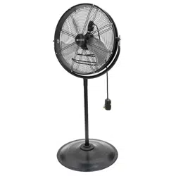
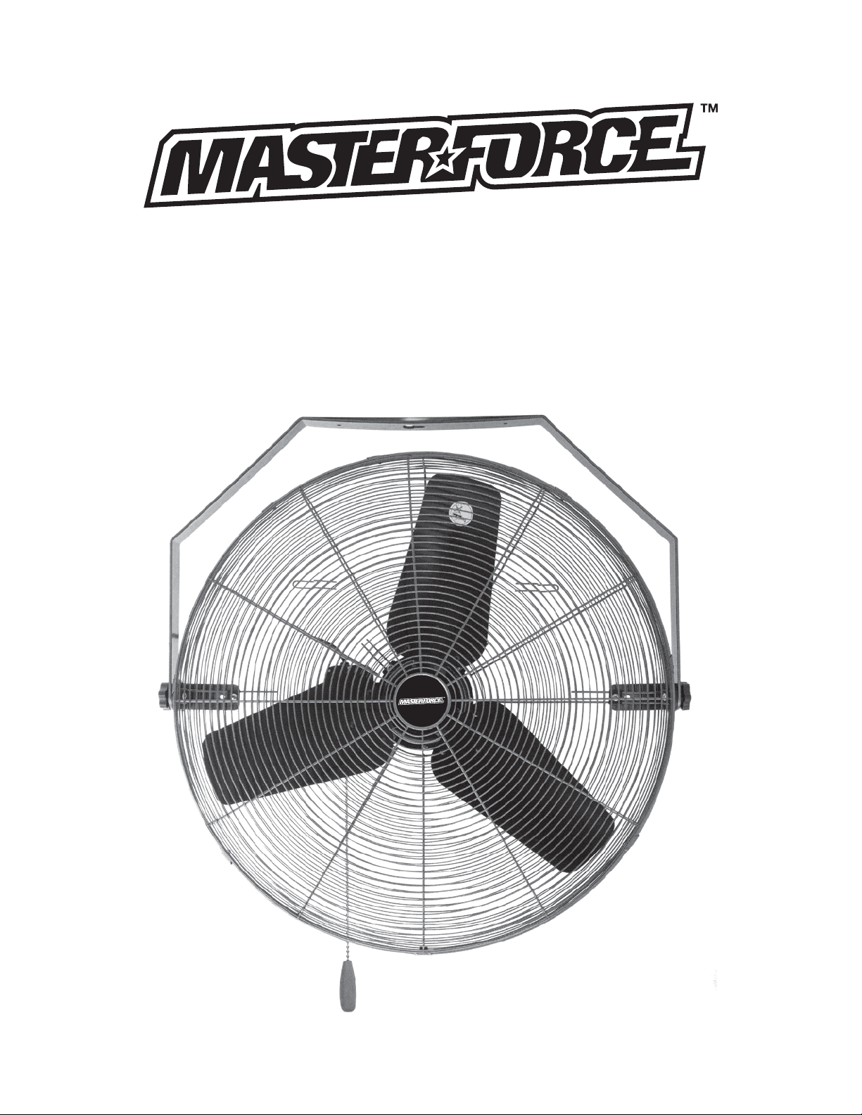
30”HIGH VELOCITY
OUTDOOR INDUSTRIAL WALL/CEILING FAN
MODEL HVOD-30NG
OWNER’S MANUAL
READ AND SAVE THESE INSTRUCTIONS.
621-1 766

2
ASSEMBLY AND OPERATING INSTRUCTIONS
CAUTION:
Read and follow all instructions before operating fan.
Do not use fan if any part is damaged or missing.
WARNING:
To reduce the risk of fire or electrical shock, do not use this fan with any solid stated speed control
device.
This appliance has a 3-prong plug. To reduce the risk of electrical shock, this plug is intended to fit in
an outlet only one way. If this does not fit the outlet, contact a qualified electrician. Do not attempt to
bypass this procedure.
RULES FOR SAFE OPERATION:
• Never insert fingers or any other objects through the grill guard when fan is in operation.
• Unplug the fan before moving from one location to another.
• Unplug the fan before removing guards for cleaning.
• Do not use with an extension cord.
• Do not place fan or any parts near an open flame, cooking appliance, or any other heat source.
• Do not use fan in windows.
• Only plug fan into GFCI protected receptacles.
ASSEMBLY INSTRUCTIONS: Wall or Ceiling Mounting – Permanent Mounting Only
1. Locate solid wall stud or ceiling beam. Mark the center of the beam. If you do not
have a solid structural framing member at that location then
you must provide an adequate alternative for mounting the
fan.
2. Drill pilot hole for 3/8” lag bolt.
3. Secure with Proper Hardware, (not included).
NOTE: Only plug fan into a GFCI outlet.
OPERATING INSTRUCTIONS
1. To Direct Vertical Airflow: Tilt the fan head up or down to the
desired angle and lock in place using securing assist knobs
on side of frame.
2. To direct Horizontal Airflow: Rotate the fan head right or left to attain the desired directional air
flow and Not provided.
3. Speed Control: Pull Switch to Low, Medium or High speeds for desired air velocity. It is normal
for the motor to feel warm to touch during continuous operation. This fan features a thermostat
that will automatically shut off should it overheat for any reason. If this happens, immediately
unplug the fan from the outlet.
KNOB
MOUNTING
LAG BOLT
LOCKING
SCREW
3
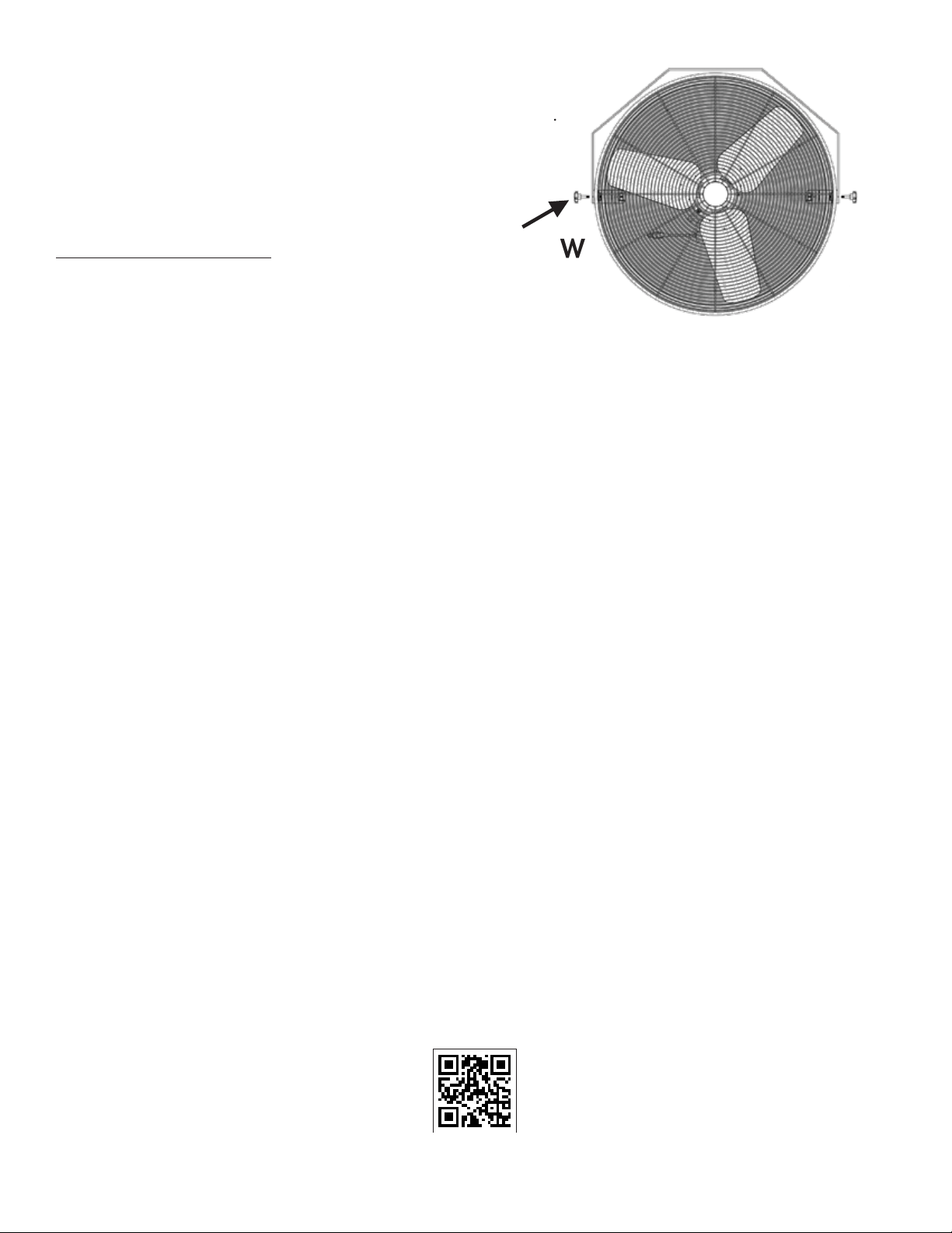
How To Adjust Tilt
1. Use knob screw to loosed by turning counter-clockwise.
2. Adjust fan head to tilt you want.
3. Tightened the knob screw by turning clockwise.
CLEANING INSTRUCTIONS
WARNING:
Unplug from electrical supply source before cleaning. After servicing, any safety device (including
grilles and blades) must be reinstalled or remounted as previously installed:
• Use soft damp cloth to clean. Then wipe with dry cloth.
• Do not use harmful cleaners.
• Do not bend the blades.
• The motor bearings are permanently sealed and do not require additional lubrication.
WARNING:
This product is not intended for use by persons (including children) with reduced physical, sensory or
mental capabilities, or lack of experience and knowledge, unless they have been given supervision or
instruction concerning use of the product by a person responsible for their safety. Children should be
supervised to ensure that they do not play with the product.
3-YEAR LIMITED WARRANTY
The manufacturer warrants this product to be free from manufacturing defects in material and
workmanship under normal use for a period of three (3) years after the date of purchase by the
original purchaser. To obtain warranty service, you must present a copy of the receipt as proof of
purchase. This warranty does not cover transit damages. This warranty does not apply to damages
from accident, faulty installation, misuse, abuse, alteration of any kind of fan or where the
connected voltage is more than 5%above the nameplate voltage. This warranty does not apply to
the finish on any portion of the product. Servicing performed by unauthorized persons shall render
the warranty invalid.
Some states do not allow the limitation or exclusion of certain damages. Therefore, these limitations
and exclusions may not apply to you. This warranty gives the consumer specific legal rights. You may
have other rights that vary from state to state.
KNOB SCREW
For warranty service contact Customer Service at
1-888-372-8518, 7:00 a.m. - 4:00 p.m., PST, Monday - Friday.
NOW YOU CAN REGISTER ONLINE
www.masterforce.info

If you have any problems, operation questions or comments about this
product, contact us toll free at 1-888-372-8518 from 7:00 a.m. to 4:00 p.m. PST,
Monday to Friday or email us at customerser[email protected]
4
No. Part Name No. Part Name
1 REAR SWITCH BOX 9 NUT BRACKET
2 CABLE HEAD 10 KNOB SCREW
3 POWER CORD 11 WASHER
4 CAPACITOR 12 ASSEMBLY BASE
5 CAPACITOR 13 REAR GRILL
6 GASKET 14 STEEL WASHER
7 FRONT SWITCH BOX 15 BLADE
8 MOTOR 16 FRONT GRILL
30″ HIGH VELOCITY DIAGRAM