Home
Bookmarks
Home
JET
JET GH-1440B User Manual
Page 53
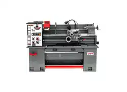
JET GH-1440B Geared Head Bench Lathe
Manual - Page 53
For GH-1440B.
PDF File Manual
,
56 pages
,
Read Online
|
Download pdf file
Geared Head Bench Lathe 14x40 inch
1.0 IMPORTANT SAFETY INSTRUCTIONS
2.0 About this manual
3.0 Table of contents
4.0 Specifications
5.0 Setup and assembly
5.1 Shipping contents
5.2 Uncrating and cleanup
5.3 Chuck preparation (three jaw)
5.4 Chuck guard installation
6.0 Lubrication
7.0 Electrical connections
7.1 GROUNDING INSTRUCTIONS
7.2 Extension cords
8.0 General description
8.1 Lathe bed
8.2 Carriage
8.3 Headstock
8.4 Quick change tool post
8.5 Apron
8.6 Tailstock
8.7 Leadscrew and feed rod
8.8 Gear box
8.9 Steady rest
8.10 Follow rest
9.0 Controls
10.0 Operation
10.1 Break-in procedure
10.2 Feed and thread selection
10.3 Change gear replacement
10.4 Automatic feed operation and feed changes
10.5 Powered carriage travel
10.6 Thread cutting
11.0 Adjustments
11.1 Saddle adjustment
11.2 Cross slide adjustment
11.3 Compound slide adjustment
11.4 Tailstock adjustment
11.5 Half nut gib adjustment
11.6 Headstock alignment
11.7 Removing gap bridge
11.8 Installing gap bridge
12.0 Thread and feed chart
13.0 Replacement parts
13.1.1 Bed Assembly â Exploded View
13.1.2 Bed Assembly â Parts List
13.2.1 Headstock Assembly â Exploded View
13.2.2 Headstock Assembly â Parts List
13.3.1 Headstock Controls â Exploded View
13.3.2 Headstock Controls â Parts List
13.4.1 Stand and Brake Assembly â Exploded View
13.4.2 Stand and Brake Assembly â Parts List
13.5.1 Gear Box Assembly â Exploded View I
13.5.2 Gear Box Assembly â Exploded View II
13.5.3 Gear Box Assembly â Parts List
13.6.1 Change Gears and Cover Assembly â Exploded View
13.6.2 Change Gears and Cover Assembly â Parts List
13.7.1 Apron Assembly â Exploded View
13.7.2 Apron Assembly â Parts List
13.8.1 Cross Slide Assembly â Exploded View
13.8.2 Cross Slide Assembly â Parts List
13.9.1 Compound Rest Assembly â Exploded View
13.9.2 Compound Rest Assembly â Parts List
13.10.1 Tailstock Assembly â Exploded View
13.10.2 Tailstock Assembly â Parts List
13.11.1 Coolant and Work Light â Exploded View
13.11.2 Coolant and Work Light â Parts List
13.12.1 Electrical Box Assembly â Exploded View
13.12.2 Electrical Box Assembly â Parts List
13.13.1 Steady Rest and Follow Rest â Parts List
13.13.2 Steady Rest and Follow Rest â Parts List
13.14.1 Chuck and Leadscrew Guards â Exploded View
13.14.2 Chuck and Leadscrew Guards â Parts List
13.15.1 Accessories â Exploded View
13.15.2 Accessories â Parts List
14.0 Electrical connections â GH-1440B Lathe
15.0 Warranty and service
Page 53/56
Page 1
Page 2
Page 3
Page 4
Page 5
Page 6
Page 7
Page 8
Page 9
Page 10
Page 11
Page 12
Page 13
Page 14
Page 15
Page 16
Page 17
Page 18
Page 19
Page 20
Page 21
Page 22
Page 23
Page 24
Page 25
Page 26
Page 27
Page 28
Page 29
Page 30
Page 31
Page 32
Page 33
Page 34
Page 35
Page 36
Page 37
Page 38
Page 39
Page 40
Page 41
Page 42
Page 43
Page 44
Page 45
Page 46
Page 47
Page 48
Page 49
Page 50
Page 51
Page 52
Page 53
Page 54
Page 55
Page 56
Contents
Table of Contents
Search
Previous
Next
Bookmarks
Loading ...
Loading ...
Loading ...
53
13.15.1
Accessories – Exploded View
Loading ...
Loading ...
Loading ...
File type: PDF
File name: 66206897_gh-1440b.pdf
File size: 5.1 MB
File Language: English
Pages: 56
Author: JET
File created: 2019-06-11
Published:
2023-04-18
Updated: 2023-04-18
Download File
Table of Contents
×
Geared Head Bench Lathe 14x40 inch
1
1.0 IMPORTANT SAFETY INSTRUCTIONS
2
2.0 About this manual
3
3.0 Table of contents
4
4.0 Specifications
6
5.0 Setup and assembly
8
5.1 Shipping contents
8
5.2 Uncrating and cleanup
9
5.3 Chuck preparation (three jaw)
9
5.4 Chuck guard installation
10
6.0 Lubrication
10
7.0 Electrical connections
11
7.1 GROUNDING INSTRUCTIONS
11
7.2 Extension cords
12
8.0 General description
12
8.1 Lathe bed
12
8.2 Carriage
12
8.3 Headstock
12
8.4 Quick change tool post
12
8.5 Apron
13
8.6 Tailstock
13
8.7 Leadscrew and feed rod
13
8.8 Gear box
13
8.9 Steady rest
13
8.10 Follow rest
13
9.0 Controls
13
10.0 Operation
15
10.1 Break-in procedure
15
10.2 Feed and thread selection
15
10.3 Change gear replacement
15
10.4 Automatic feed operation and feed changes
15
10.5 Powered carriage travel
15
10.6 Thread cutting
16
11.0 Adjustments
16
11.1 Saddle adjustment
16
11.2 Cross slide adjustment
16
11.3 Compound slide adjustment
16
11.4 Tailstock adjustment
16
11.5 Half nut gib adjustment
16
11.6 Headstock alignment
17
11.7 Removing gap bridge
17
11.8 Installing gap bridge
17
12.0 Thread and feed chart
18
13.0 Replacement parts
18
13.1.1 Bed Assembly â Exploded View
19
13.1.2 Bed Assembly â Parts List
20
13.2.1 Headstock Assembly â Exploded View
22
13.2.2 Headstock Assembly â Parts List
23
13.3.1 Headstock Controls â Exploded View
25
13.3.2 Headstock Controls â Parts List
26
13.4.1 Stand and Brake Assembly â Exploded View
27
13.4.2 Stand and Brake Assembly â Parts List
28
13.5.1 Gear Box Assembly â Exploded View I
29
13.5.2 Gear Box Assembly â Exploded View II
30
13.5.3 Gear Box Assembly â Parts List
31
13.6.1 Change Gears and Cover Assembly â Exploded View
33
13.6.2 Change Gears and Cover Assembly â Parts List
34
13.7.1 Apron Assembly â Exploded View
35
13.7.2 Apron Assembly â Parts List
36
13.8.1 Cross Slide Assembly â Exploded View
38
13.8.2 Cross Slide Assembly â Parts List
39
13.9.1 Compound Rest Assembly â Exploded View
40
13.9.2 Compound Rest Assembly â Parts List
41
13.10.1 Tailstock Assembly â Exploded View
43
13.10.2 Tailstock Assembly â Parts List
44
13.11.1 Coolant and Work Light â Exploded View
45
13.11.2 Coolant and Work Light â Parts List
46
13.12.1 Electrical Box Assembly â Exploded View
47
13.12.2 Electrical Box Assembly â Parts List
48
13.13.1 Steady Rest and Follow Rest â Parts List
49
13.13.2 Steady Rest and Follow Rest â Parts List
50
13.14.1 Chuck and Leadscrew Guards â Exploded View
51
13.14.2 Chuck and Leadscrew Guards â Parts List
52
13.15.1 Accessories â Exploded View
53
13.15.2 Accessories â Parts List
54
14.0 Electrical connections â GH-1440B Lathe
55
15.0 Warranty and service
56
Search:
×
Search