Loading ...
Loading ...
Loading ...

12
This tool is intended for use on a circuit that has an
outlet that looks like the one illustrated in Figure 7-
1. The tool is intended for use with a grounding
plug that looks like the plug illustrated in Figure 7-
1. Make sure the tool is connected to an outlet
having the same configuration as the plug. No
adapter is available or should be used with this
tool. If the tool must be reconnected for use on a
different type of electric circuit, the reconnection
should be made by qualified service personnel;
and after reconnection, the tool should comply with
all local codes and ordinances.
If hardwired:
Permanently connected tools: This tool should be
connected to a grounded metal permanent wiring
system; or to a system having an equipment-
grounding conductor.
Figure 7-1
7.2 Extension cords
The use of extension cords is discouraged; try to
position equipment within reach of the power
source. If an extension cord becomes necessary,
be sure it is heavy enough to carry the current your
product will draw. An undersized cord will cause a
drop in line voltage resulting in loss of power and
overheating.
Table 1 shows recommended size to use
depending on cord length and nameplate ampere
rating. If in doubt, use the next heavier gauge. The
smaller the gauge number, the heavier the cord.
Ampere
Rating
Volts
Total length of
cord in feet
More
Than
Not
More
Than
240 50 100 200 300
AWG
00 06 18 16 16 14
06 10 18 16 14 12
10 12 16 16 14 12
12 16 14 12
Not
Recommended
Table 2: Extension cord recommendations
8.0 General description
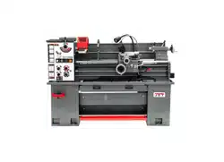
8.1 Lathe bed
The lathe bed (A, Figure 8-1) is made of high grade
cast iron. By combining high cheeks with strong
cross ribs, a bed with low vibration and high rigidity
is realized. Two precision ground V-slideways,
reinforced by heat hardening and grinding, are an
accurate guide for the carriage and headstock. The
main drive motor is mounted to the rear of the bed.
Figure 8-1
8.2 Carriage
The carriage (B, Fig. 10) is made from high quality
cast iron. The sliding parts are smooth ground. The
cross-slide is mounted on the carriage and moves
on a dove-tailed slide which can be adjusted for
play by means of gibs.
The compound slide (C, Figure 8-1), which is
mounted on the cross slide (D, Figure 8-1), can be
rotated through 360°. The compound slide and the
cross slide travel in a dovetail slide and have
adjustable gibs. A four-way tool post (E, Figure 8-
1) is fitted on the compound slide.
8.3 Headstock
The headstock (F, Figure 8-1) is cast from high
grade, low vibration cast iron. It is mounted to the
bed by four bolts with two adjusting bolts for
alignment. In the head, the spindle is mounted on
two precision taper roller bearings. The hollow
spindle has Morse Taper #6 with a 2" bore.
8.4 Quick change tool post
The quick change tool post (E, Figure 8-1) is
mounted on the compound slide and allows tool
holders to be mounted easily. Remember to use a
minimum of two clamping screws when installing a
cutting tool.
Loading ...
Loading ...
Loading ...