Loading ...
Loading ...
Loading ...
13
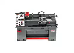
Figure 8-2
8.5 Apron
The apron (A, Figure 8-2) is mounted to the
carriage. In the apron a half nut is fitted. The half
nut gibs can be adjusted from the outside. The half
nut is engaged by use of a lever. Quick travel of
the apron is accomplished by means of a bed-
mounted rack and pinion, operated by a
handwheel on front of apron.
8.6 Tailstock
The tailstock (B, Figure 8-2) slides on a v-way and
can be locked at any location by a clamping lever.
The tailstock has a heavy-duty spindle with a
Morse Taper #4.
8.7 Leadscrew and feed rod
The leadscrew (C Figure 8-2) and feed rod (D,
Figure 8-2) are mounted on the front of machine
bed. They are connected to the gearbox at the left
for automatic feed and lead. They are supported by
bushings on both ends.
8.8 Gear box
The gear box (E, Figure 8-2) is made from high
quality cast iron and is mounted to left side of
machine bed.
8.9 Steady rest
The steady rest (F, Figure 8-2) serves as a support
for shafts on the free tailstock end. The steady rest
is mounted on the bedway and secured from below
with bolt, nut and locking plate.
8.10 Follow rest
The traveling follow rest (G, Figure 8-2) is mounted
on the saddle and follows the movement of the
turning tool. Only two fingers are required as the
turning tool takes the place of the third. The follow
rest is used for tuning operations on long, slender
workpieces. It prevents flexing of the workpiece
from the pressure of the cutting tool.
The sliding fingers are set similar to the steady
rest, free of play, but not binding. The sliding
fingers require continuous lubrication at the contact
points with the workpiece to prevent premature
wear.
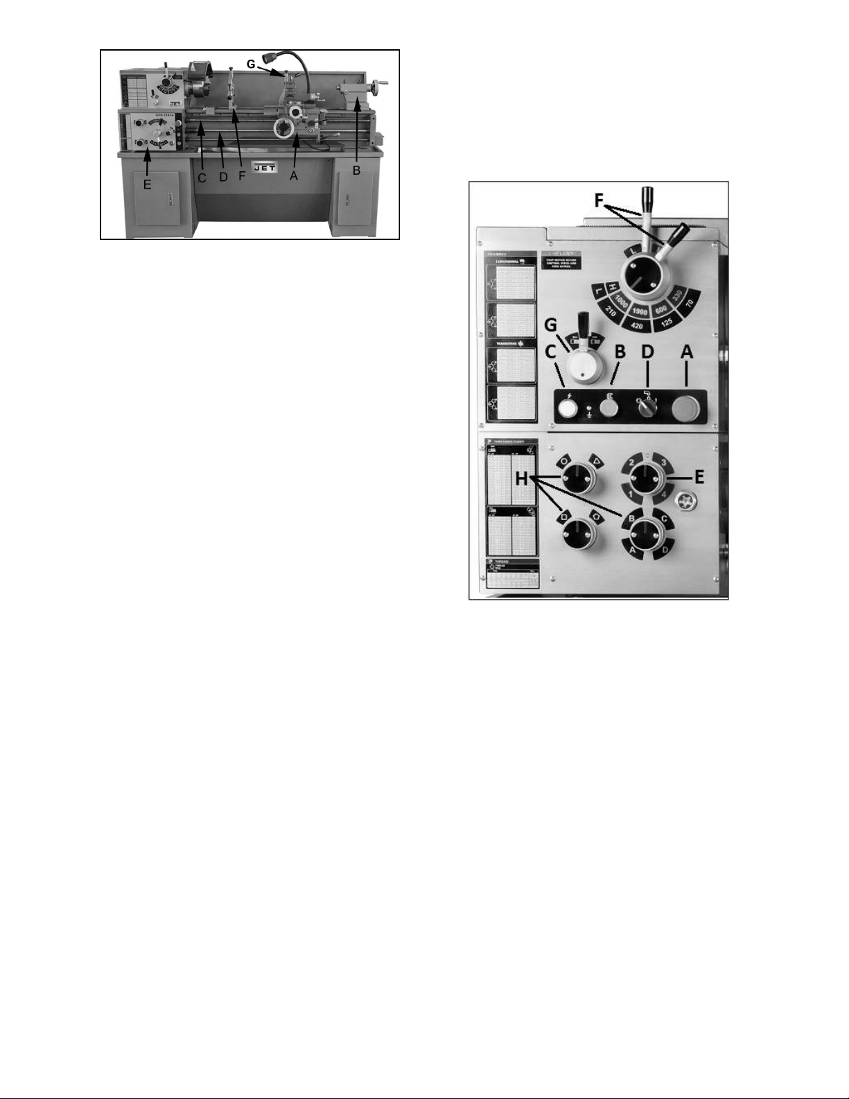
9.0 Controls
Figure 9-1
1. Emergency Stop Switch (A, Figure 9-1) –
Press to stop all machine functions. Caution:
lathe will still have power. To restart
machine, rotate button clockwise until it
disengages.
2. Jog Switch (B, Figure 9-1) – Press and
release to advance spindle momentarily.
3. Power Indicator Light (C, Figure 9-1) –
Illuminated whenever lathe has power.
4. Coolant On-Off Switch (D, Figure 9-1) –
Turns coolant pump on and off.
5. Feed Rod/Leadscrew Selector (E, Figure 9-
1) – Use knob to activate leadscrew and feed
rod.
6. Speed Selector Levers (F, Figure 9-1) – Use
to select spindle speeds in ranges.
7. Feed Direction Selector (G, Figure 9-1) –
Selects carriage travel direction when chuck is
rotating in forward direction (or counter-
clockwise as viewed from front of chuck).
8. Feed Rate Selector (H, Figure 9-1) – Use
knobs to set desired feed, or lead rates.
Loading ...
Loading ...
Loading ...