
Loading ...
Loading ...
Loading ...
14
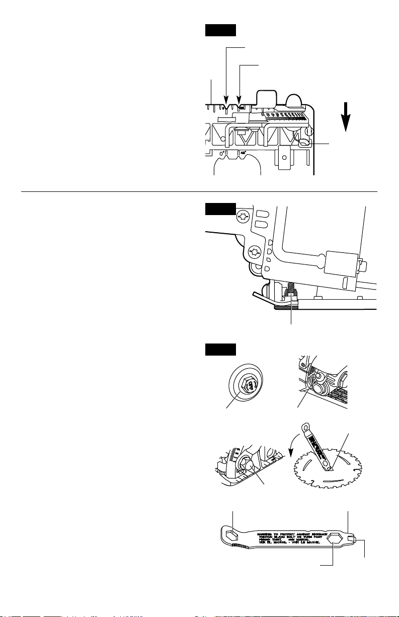
Fig. 6
45° Bevel
Cuts
45° Stop
Spring
Push the 45°
Stop Spring
In Direction
Of Arrow
For Bevel
Adjustments
Above 45°
Foot
0° Cuts
LINE GUIDE (FIG. 6)
For a 0° cut, use the large notch in the foot
for guidance . For 45° bevel cuts, use the
small notch (Fig. 6). The cutting guide notch
will indicate an approximate line of cut. Make
sample cuts in scrap lumber to verify the
actual line of cut. This will be helpful because
of the number of different blade types and
thicknesses available. To ensure minimum
splintering on the good side of the material to
be cut, face the good side down.
MAXIMUM DEPTH OF CUT STABILITY
ADJUSTMENT
Note: Feature is set during assembly.
Adjustment may be required due to wear and
tear on the tool.
Remove the battery pack from the circular saw
and set the saw to zero bevel. Place the foot plate
on a level surface with rear of foot over hanging
work the bench by about 2 inches. Loosen the
depth-adjustment lever. Set the saw to maximum
depth of cut. If the adjustment set screw is in
contact with the motor housing prior to achieving
maximum depth of cut, lower set screw using a
1/18” Allen wrench until the maximum depth of
cut is reached. If the set screw is not in contact
with the motor housing when the maximum depth
of cut is reached, raise the set screw until it just
engages the motor housing (Fig. 7a).
WRENCH USAGE (FIG. 7B FIG. 8)
The wrench provided has several functions in
addition to loosening/tightening the blade bolt
(Fig. 7b):
1. Loosening/tightening the blade bolt (1/2”
wrench).
2. Loosening/tightening the combo oil plug/
lock-button assembly (1/2” wrench).
3. Loosening/tightening bevel/depth levers
when levers are over tightened or additional
tightening is needed (9/16” wrench).
4. Blade diamond arbor knock out (wedge
feature).
Storage is provided on the tool (Fig. 1a). The
wrench is fully seated when the second lock
detent is engaged.
Fig. 7b
1 2
4
3
1/2" Wrench Wedge Feature
Slotted
Driver
9/16" Wrench
Fig. 7a
Set Screw
Loading ...
Loading ...
Loading ...