1
Owner’s Manual
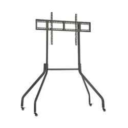
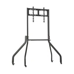
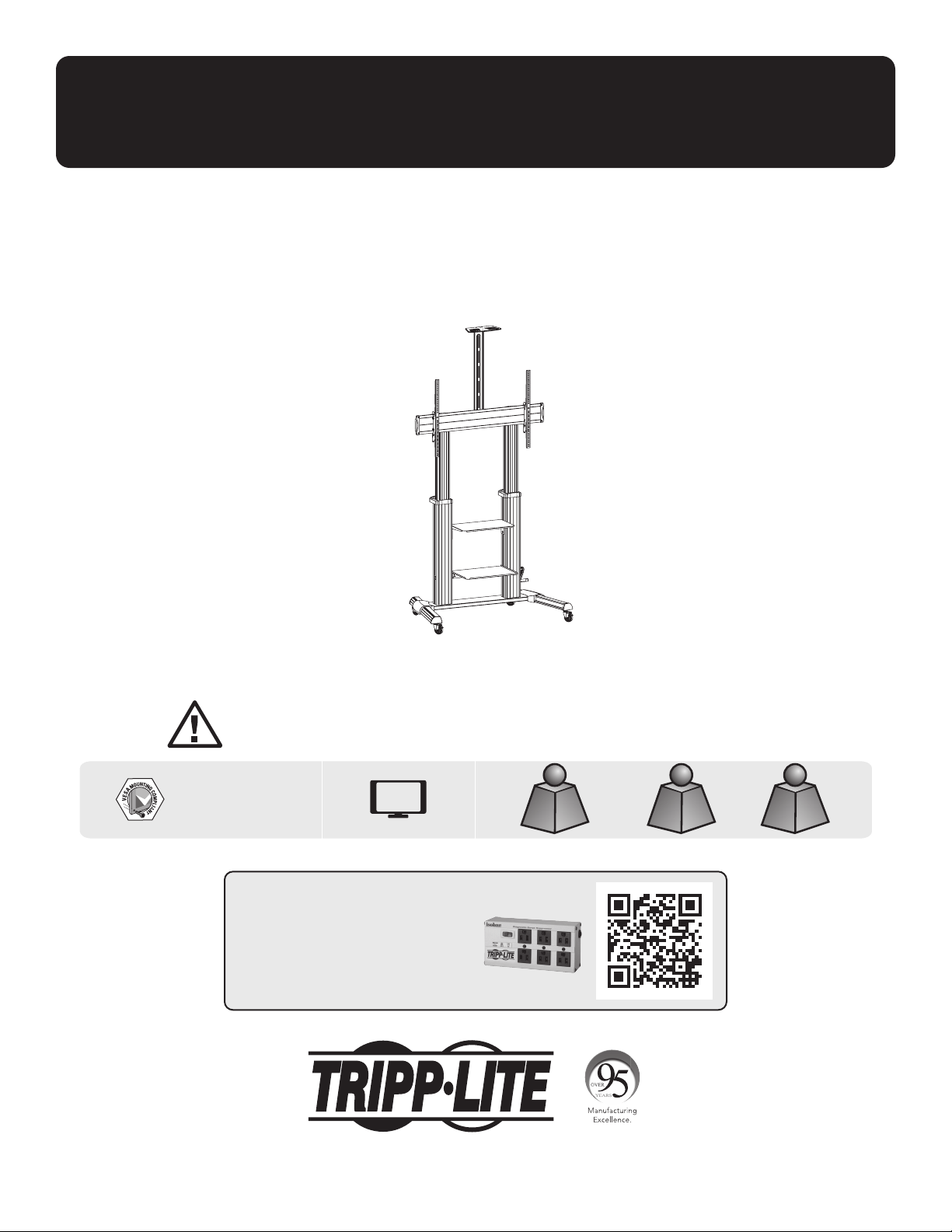
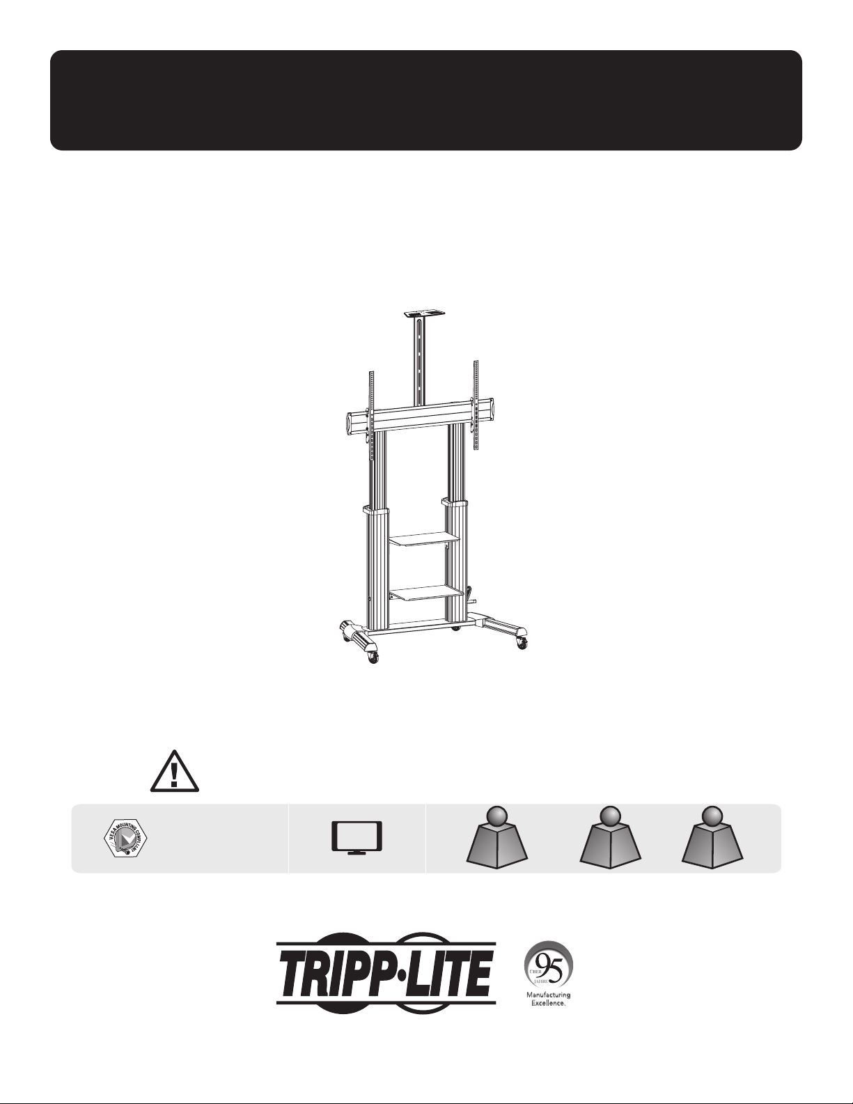
Heavy-Duty Rolling TV/Monitor Cart
with Crank Handle
Model: DMCS60100XXCK
1111 W. 35th Street, Chicago, IL 60609 USA • tripplite.com/support
Copyright © 2021 Tripp Lite. All rights reserved.
WARRANTY REGISTRATION
Register your product today and be
automatically entered to win an ISOBAR
®
surge protector in our monthly drawing!
tripplite.com/warranty
CAUTION: DO NOT EXCEED MAXIMUM LISTED WEIGHT CAPACITY. SERIOUS INJURY OR PROPERTY DAMAGE MAY OCCUR!
200 x 200 / 300 x 300
400 x 200 / 400 x 400
600 x 400 / 800 x 400
800 x 600 / 1000 x 600
100"
MAX
TVTV
220 lb./100 kg220 lb./100 kg
MAXMAX
DVDDVD
11 lb./5 kg (x2)11 lb./5 kg (x2)
MAXMAX
CAMERACAMERA
11 lb./5 kg11 lb./5 kg
MAXMAX
Español 12 • Français 23 • Русский 34 • Deutsch 45

2
Safety Instructions
Warranty and Product Registration
WARNING
• Do not begin the installation until you have read and understood the instructions and warnings contained in this
manual. If you have any questions regarding any of the instructions or warnings, please visit tripplite.com/support.
• This mounting bracket was designed to be installed and utilized ONLY as specified in this manual. Improper installation
of this product may cause damage or serious injury.
• This product should only be installed by someone of good mechanical ability, with basic building experience and a full
understanding of this instruction manual.
• Make sure that the mounting surface can safely support the combined load of the equipment and all attached hardware
and components.
• If mounting to wood wall studs, make sure that mounting screws are anchored into the center of the studs. The use of
a stud finder is highly recommended.
• Always use an assistant or mechanical lifting equipment to safely lift and position equipment.
• Tighten screws firmly, but do not over-tighten. Over-tightening screws can damage the items, greatly reducing their
holding power.
•
This product is intended for indoor use only. Using this product outdoors could lead to product failure and personal injury.
5-Year Limited Warranty
Seller warrants this product, if used in accordance with all applicable instructions, to be free from original defects in material and workmanship for a period of
5 years from the date of initial purchase. If the product should prove defective in material or workmanship within that period, Seller will repair or replace the
product, in its sole discretion.
THIS WARRANTY DOES NOT APPLY TO NORMAL WEAR OR TO DAMAGE RESULTING FROM ACCIDENT, MISUSE, ABUSE OR NEGLECT. SELLER MAKES NO
EXPRESS WARRANTIES OTHER THAN THE WARRANTY EXPRESSLY SET FORTH HEREIN. EXCEPT TO THE EXTENT PROHIBITED BY APPLICABLE LAW, ALL IMPLIED
WARRANTIES, INCLUDING ALL WARRANTIES OF MERCHANTABILITY OR FITNESS, ARE LIMITED IN DURATION TO THE WARRANTY PERIOD SET FORTH ABOVE;
AND THIS WARRANTY EXPRESSLY EXCLUDES ALL INCIDENTAL AND CONSEQUENTIAL DAMAGES. (Some states do not allow limitations on how long an implied
warranty lasts, and some states do not allow the exclusion or limitation of incidental or consequential damages, so the above limitations or exclusions may
not apply to you. This warranty gives you specific legal rights, and you may have other rights, which vary from jurisdiction to jurisdiction).
WARNING: The individual user should take care to determine prior to use whether this device is suitable, adequate or safe for the use intended. Since
individual applications are subject to great variation, the manufacturer makes no representation or warranty as to the suitability or fitness of these devices
for any specific application.
PRODUCT REGISTRATION
Visit tripplite.com/warranty today to register your new Tripp Lite product. You’ll be automatically entered into a drawing for a chance to win a FREE
Tripp Lite product!*
* No purchase necessary. Void where prohibited. Some restrictions apply. See website for details.
Tripp Lite has a policy of continuous improvement. Specifications are subject to change without notice. Photos and illustrations may differ slightly from
actual products.
NOTE: Read the entire Owner’s Manual before you start installation and assembly.
3
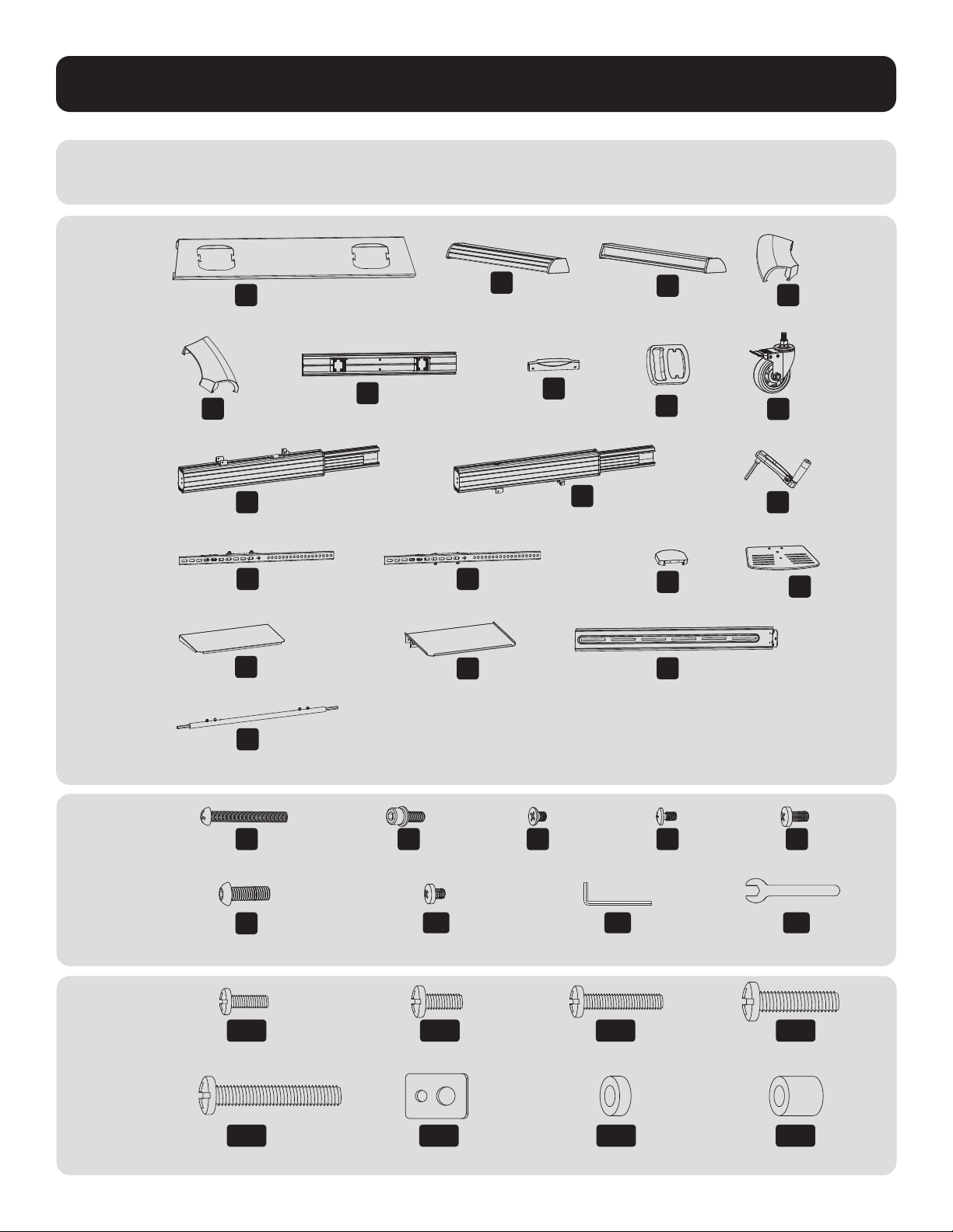
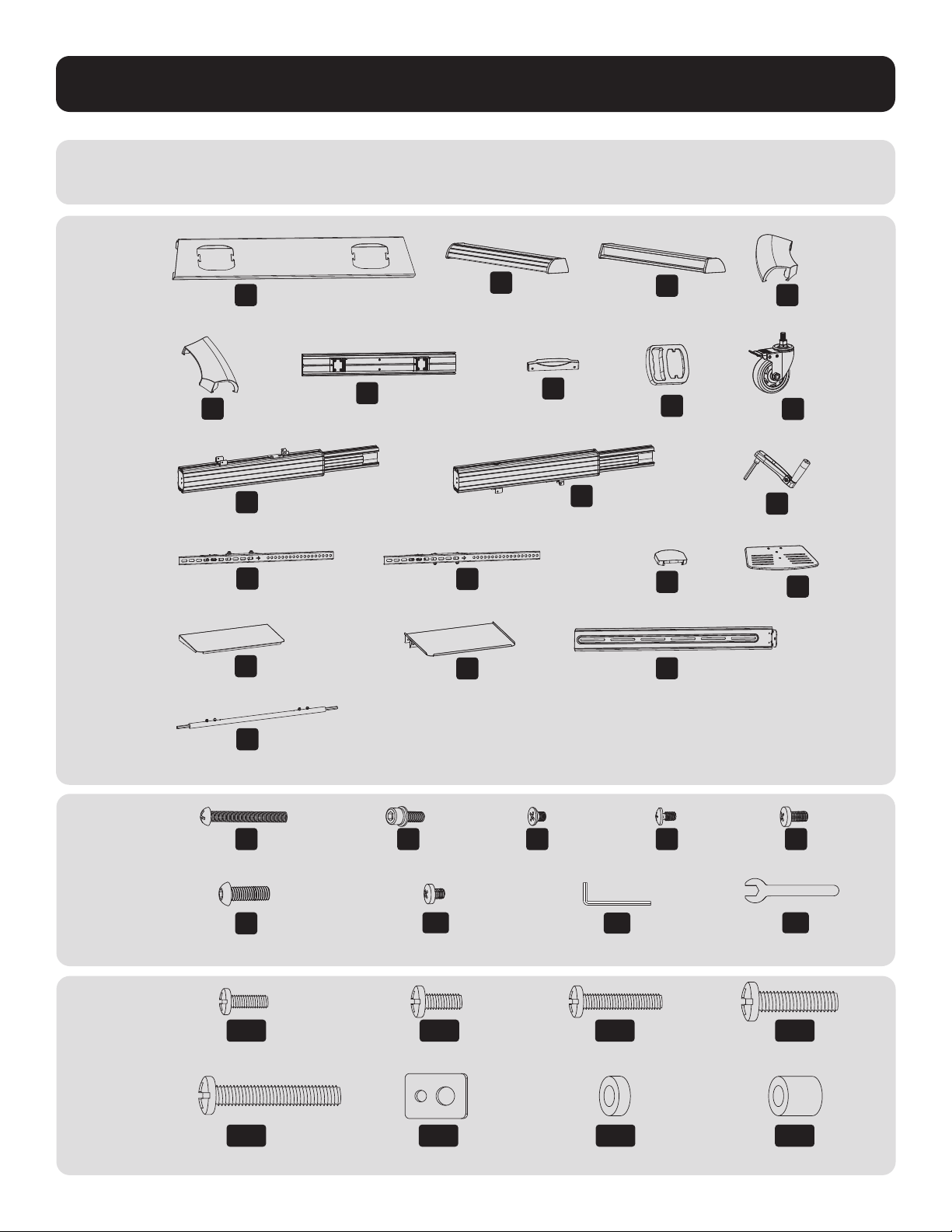
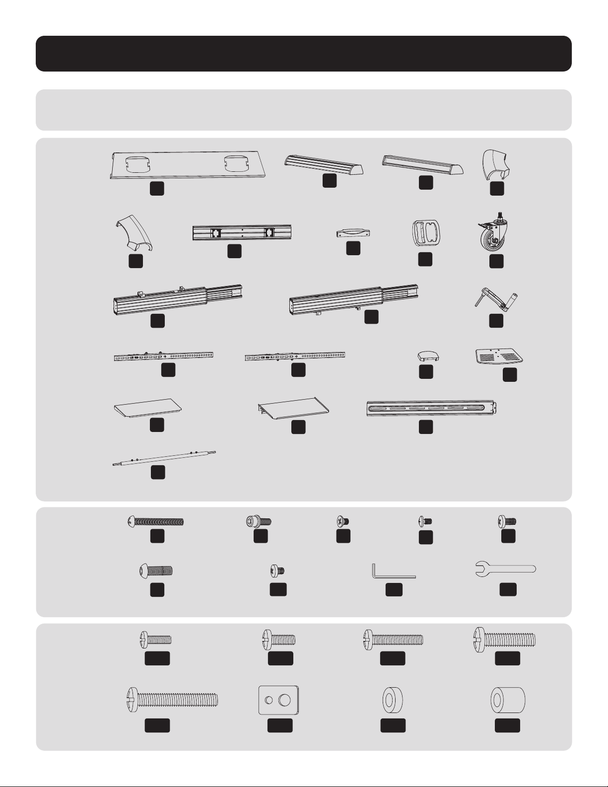
Package M
Package P
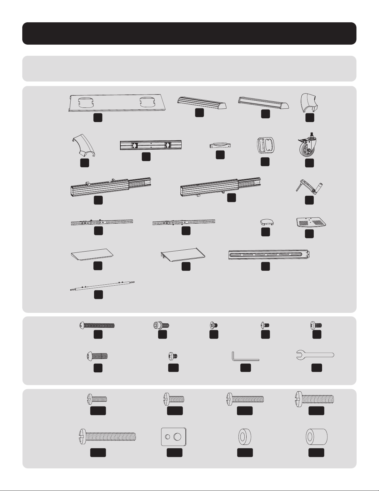
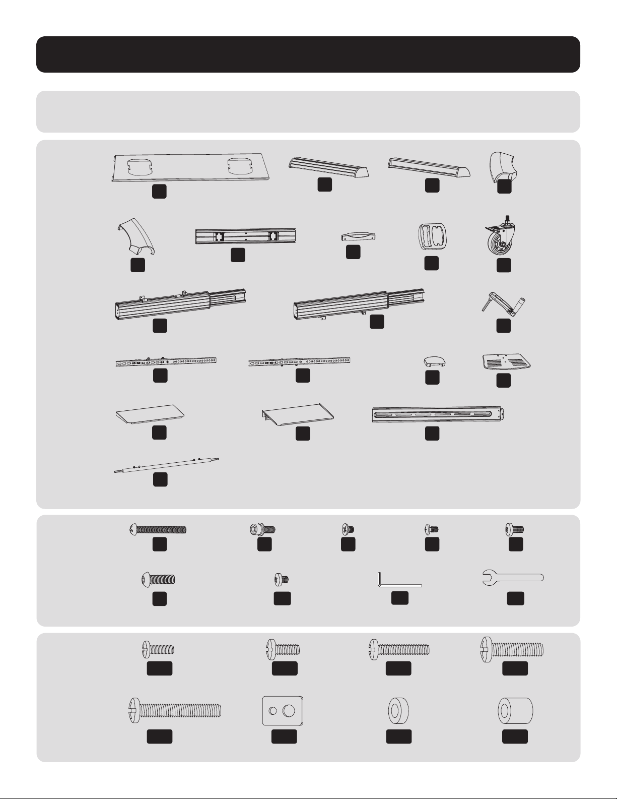
Component Checklist
IMPORTANT: Ensure you have received all parts according to the component checklist prior to installing.
If any parts are missing or faulty, visit tripplite.com/support for service.
B
Left Leg (x1)
D
Left Cover (x1)
C
Right Leg (x1)
F
Universal Plate (x1)
K
Right Column (x1)
O
Top Cover (x1)
S
Connecting Plate (x1)
E
Right Cover (x1)
J
Left Column (x1)
M
Left Adapter Bracket (x1)
Q
Upper DVD Shelf (x1)
T
Connecting Bar (x1)
N
Right Adapter Bracket (x1)
R
Lower DVD Shelf (x1)
G
Plastic Cover (x2)
L
Crank Handle (x1)
P
Camera Shelf (x1)
H
Plastic Handle (x2)
I
Caster (x4)
A
Middle Base (x1)
M-A
M5x14 (x4)
M-E
M8x50 (x4)
M-B
M6x14 (x4)
M-F
D5-D8 (x4)
M-C
M6x30 (x4)
M-D
M8x30 (x4)
M-G
Ø15xØ8x5 (x8)
M-H
Ø15xØ8x15 (x8)
Z
M8x25 (x12)
U
M5x40 (x1)
A1
M6x8 (x12)
V
M6x25 (x4)
B1
5 mm Hex Key(x1)
W
M4x6 (x3)
C1
19 mm Wrench (x1)
X
M4x6 (x3)
Y
M6x14 (x4)
4
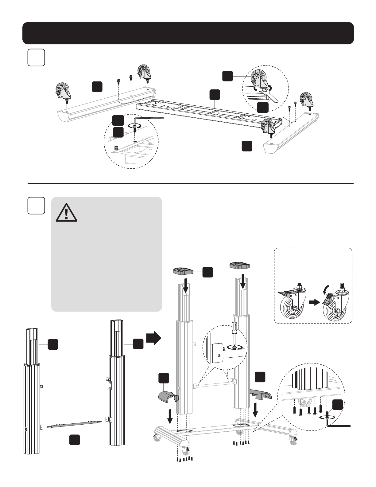
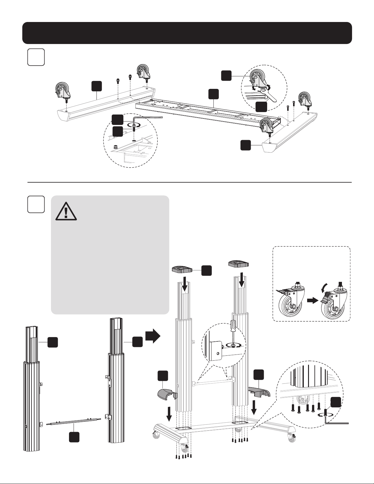
Assembly
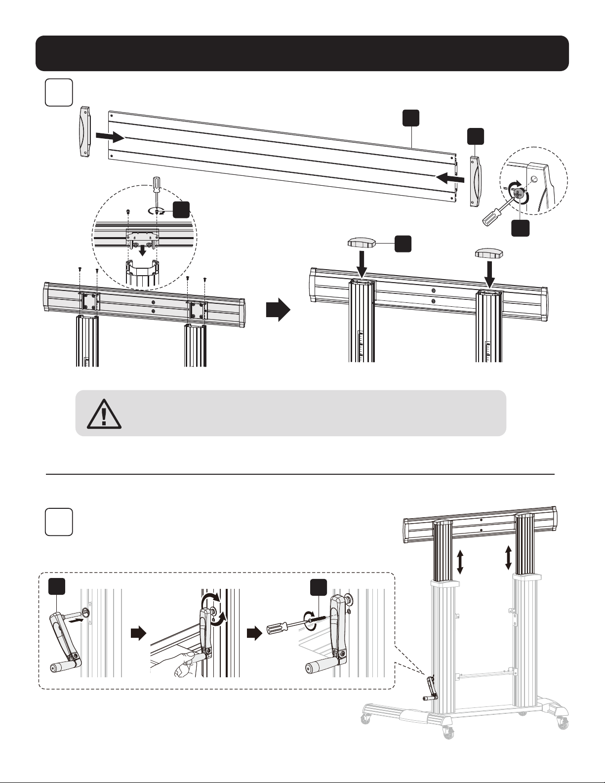
1
2
C
A
I
B
C1
B1
V
H
J
K
T
D
Z
E
Install the heavy-duty locking
casters into the threaded
caster slots. Use the wrench
(C1) to tighten the casters .
Note: Tighten the screws after
installing the connecting bar (T).
CAUTION: Hold the
inner column when
loosening screws
to adjust height.
Adjust to the desired
height, then tighten
the screws, leaving
a small gap between
screws (Z) and the
outer columns. Also,
make sure the left and
right inner columns are
at the same height.

5
Assembly
3
4
F
O
Y
G
A1
L
U
CAUTION: After assembling the universal plate (F) to the columns as
shown, tighten the screws (Z).
Note: Adjust the height with the crank handle (L), then tighten the screw (U).

6
Assembly
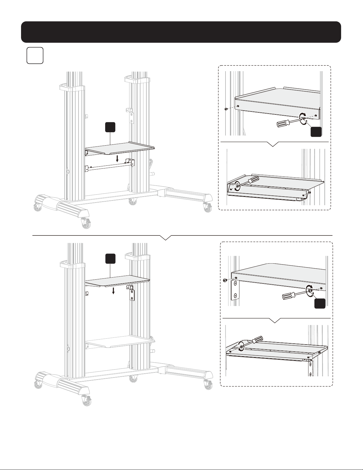
5
R
Q
A1
A1

7
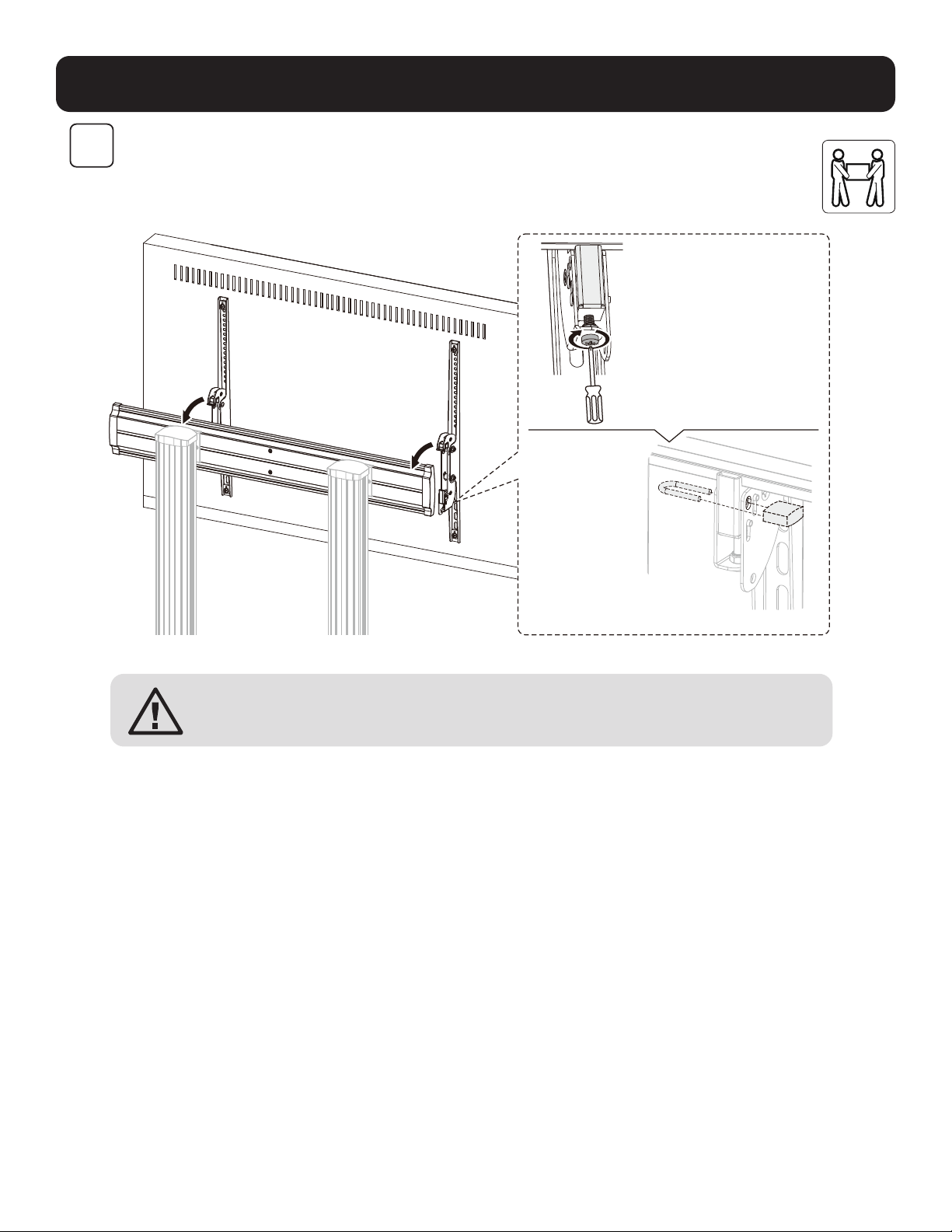
Assembly
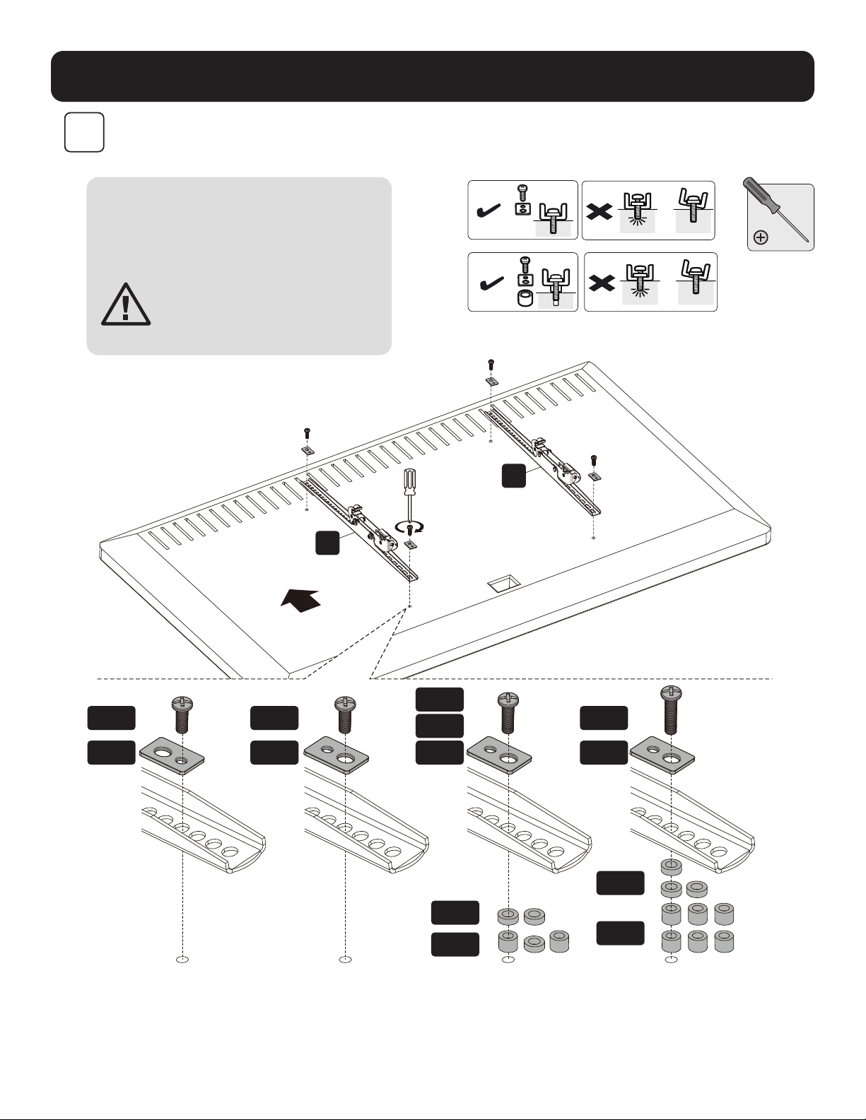
6
M-F M-F M-F
M-H
M-H
M-A M-B M-E
M-G
M-G
M-F
M-D
M-C
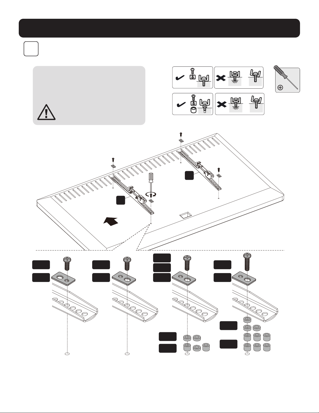
N
M
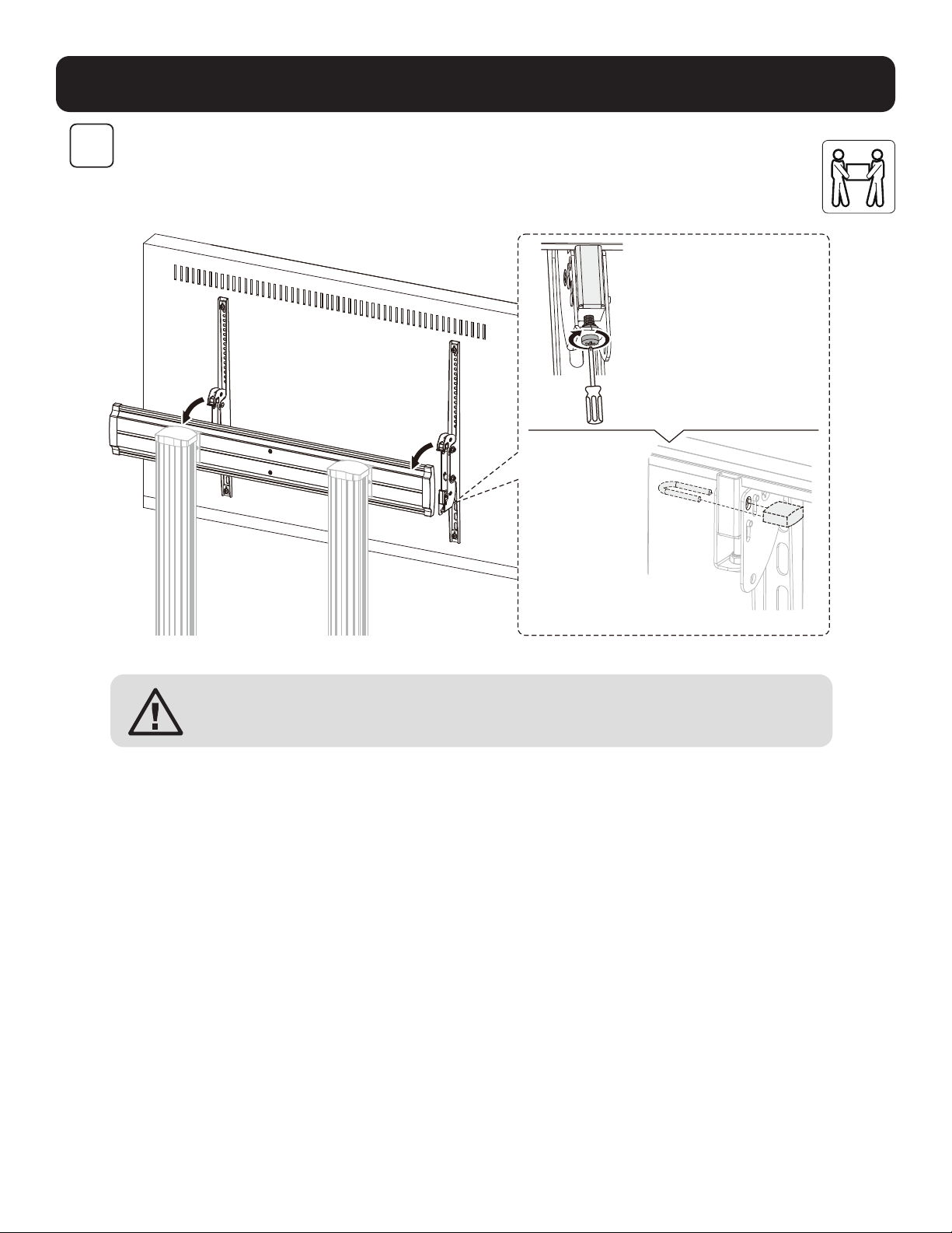
Note: Choose the appropriate screws,
washers and spacers (if needed) according
to the type of screen. Screw the adapter
brackets onto the display.
CAUTION: Tighten all screws
but do not over tighten.
TVTV
TV
TV
TV TV
TOP
8
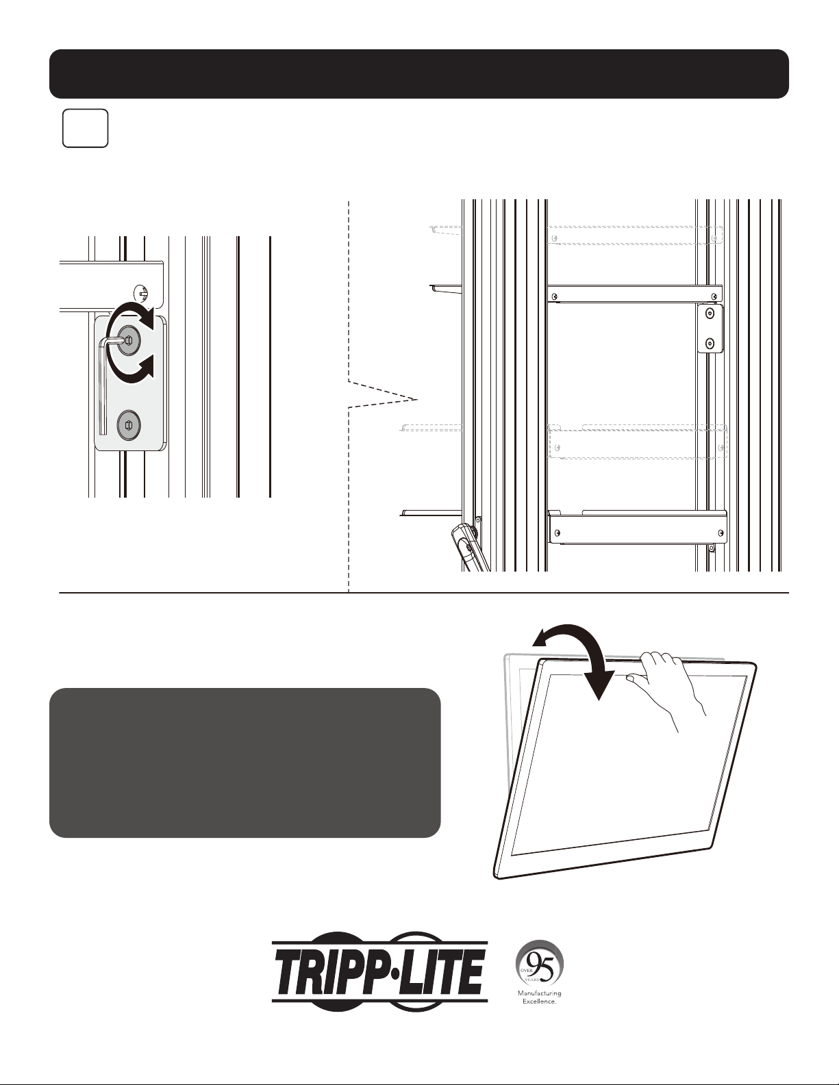
Assembly
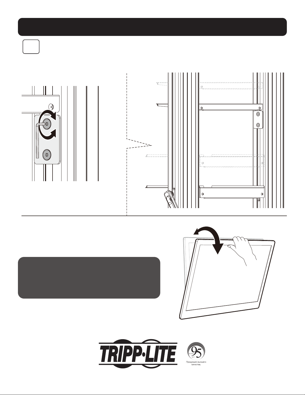
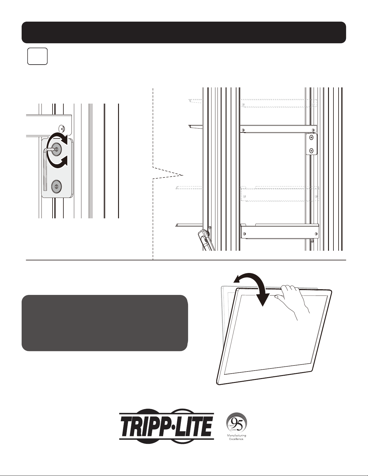
7
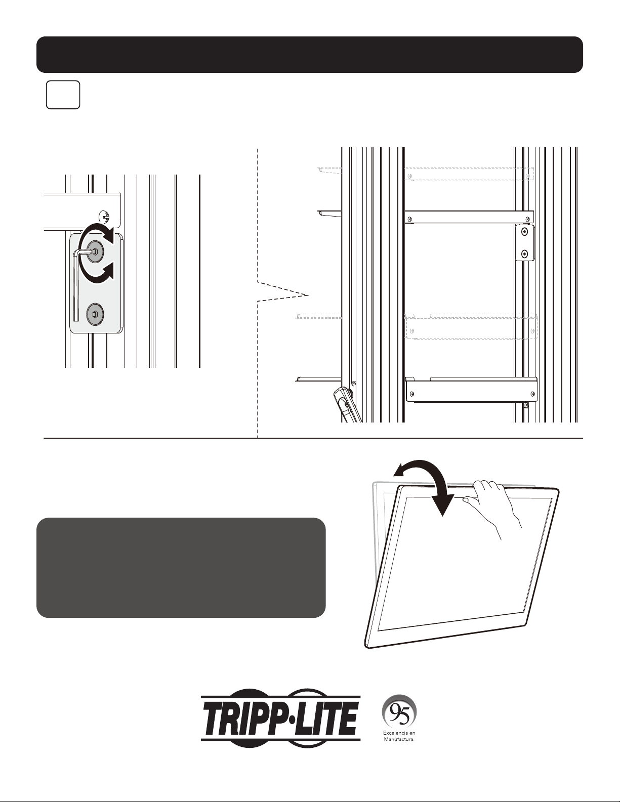
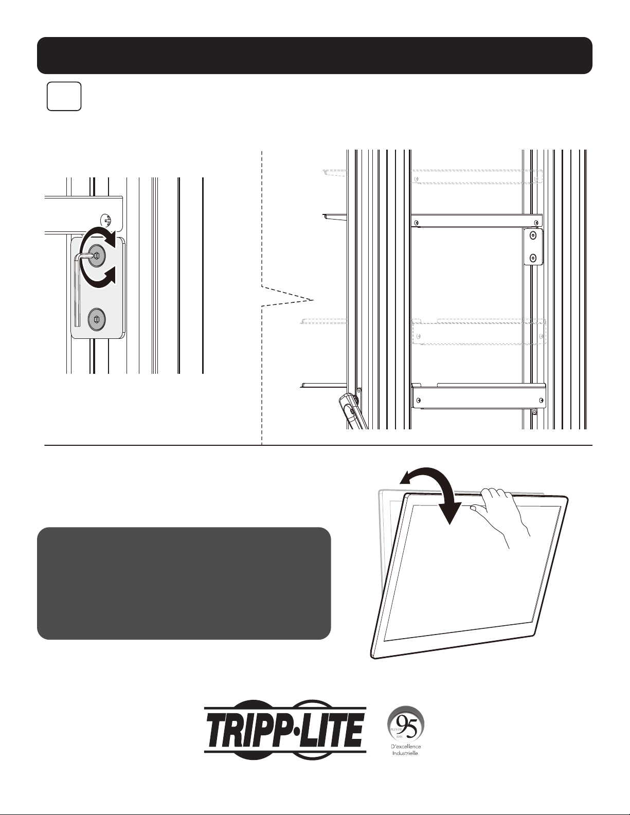
Notes:
• To lock, rotate the bottom
screws counterclockwise.
• To unlock, rotate the
bottom screws clockwise.
Note: Use a
padlock (not
included) to
protect the
display from
tampering
or theft.
CAUTION: Be sure the display is correctly mounted and the screws are securely
tightened before releasing the display.

9
Assembly
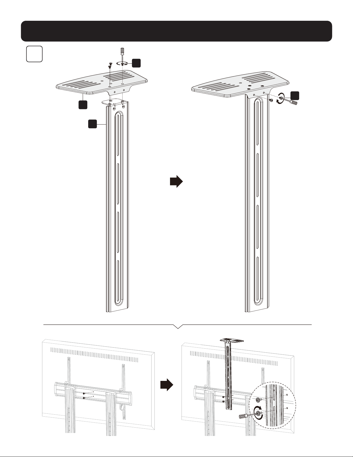
S
P
W
X
8

10
Adjustment
Keep the monitor
arm horizontal
while making
spring tension
adjustments.
Prior to any arm
movement, fully
remove the Allen
key.
(Note: DO NOT
over-tighten screw.)
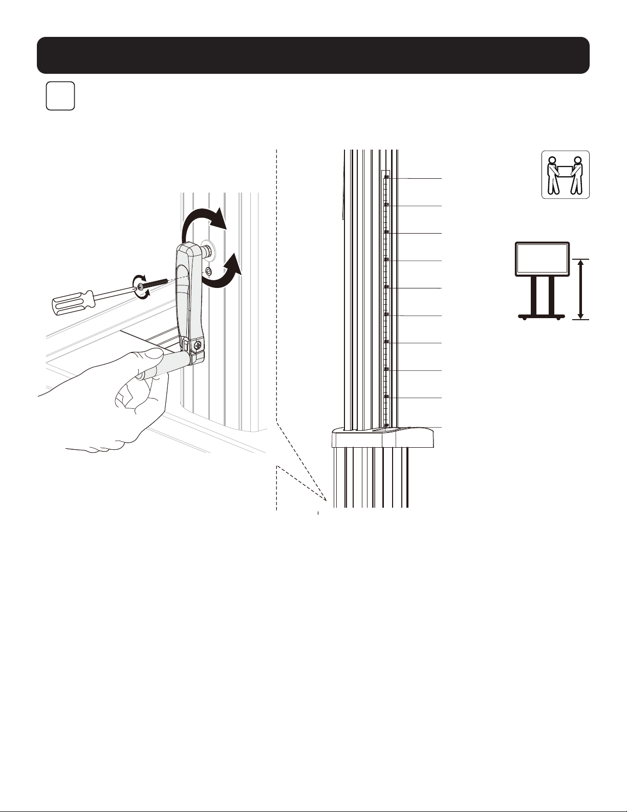
9
Note: Loosen the screw, as shown. Use the
handle to adjust the column to the desired
height, then tighten the screw to secure.
1200mm
1250mm
1300mm
1350mm
1400mm
1450mm
1500mm
1550mm
16oomm
1650mm
11
Adjustment
10
Maintenance
• Check that the bracket is secure and safe to use at regular
intervals (at least every three months).
• For any additional questions, visit tripplite.com/support.
Note: To adjust the DVD shelf to the desired
height, loosen the screws on both support
blocks, then tighten all screws to secure.
1111 W. 35th Street, Chicago, IL 60609 USA • tripplite.com/support
21-06-299 932F2F_RevA

12
MÁS DE
AÑOS
Manual del Propietario
Carro Rodante para TV/Monitor para
Servicio Pesado con Manivela
Modelo: DMCS60100XXCK
1111 W. 35th Street, Chicago, IL 60609, EE. UU. • tripplite.com/support
Copyright © 2021 Tripp Lite. Todos los derechos reservados.
PRECAUCIÓN: NO EXCEDA LA CAPACIDAD DE CARGA MÁXIMA INDICADA. ¡PUEDEN OCURRIR LESIONES SEVERAS O DAÑOS A LA
PROPIEDAD!
200 x 200 / 300 x 300
400 x 200 / 400 x 400
600 x 400 / 800 x 400
800 x 600 / 1000 x 600
100"
MÁXIMO
TVTV
100 kg [220 lb]100 kg [220 lb]
MÁXIMOMÁXIMO
DVDDVD
5 kg [11 lb] (x2)5 kg [11 lb] (x2)
MÁXIMOMÁXIMO
CÁMARACÁMARA
5 kg [11 lb]5 kg [11 lb]
MÁXIMOMÁXIMO
English 1 • Français 23 • Русский 34 • Deutsch 45

13
Instrucciones de Seguridad
Garantía
ADVERTENCIA
• No inicie la instalación hasta que haya leído y entendido las instrucciones y advertencias contenidas en este manual. Si
tiene cualquier pregunta con respecto a cualquiera de las instrucciones o advertencias, visite tripplite.com/support.
• Este soporte de instalación fue diseñado para ser instalado y utilizado SOLAMENTE como se especifica en este manual.
La instalación incorrecta de este producto puede causar daños o lesiones severas.
• Este producto debe ser instalado únicamente por alguien que posea competencia mecánica adecuada, experiencia
básica en construcción y total comprensión de este manual de instrucciones.
• Cerciórese que la superficie de instalación pueda soportar con seguridad la carga combinada de todo el equipo,
hardware y componentes instalados.
• Si se instala en paredes con travesaños de madera, cerciórese que los tornillos de instalación estén anclados en el
centro de los travesaños. Es muy recomendable usar un detector de vigas y travesaños.
• Utilice siempre un ayudante o un equipo de elevación mecánico para levantar y colocar el equipo con seguridad.
• Apriete los tornillos firmemente pero no en exceso. Al apretar excesivamente los tornillos puede dañar los
componentes, reduciendo sustancialmente su capacidad de soporte.
•
Este producto está diseñado para usarse solo en interiores. Usar este producto en exteriores podría derivar en fallas del
producto y lesiones personales.
Garantía Limitada por 5 Años
El vendedor garantiza este producto, si se usa de acuerdo con todas las instrucciones aplicables, de que está libre de defectos en cuanto a materiales y
mano de obra por un período de 5 años a partir de la fecha de compra inicial. Si el producto resultara defectuoso en cuanto a materiales o mano de obra
dentro de ese período, el vendedor reparará o reemplazará el producto a su entera discreción.
ESTA GARANTÍA NO SE APLICA AL DESGASTE NORMAL O A LOS DAÑOS QUE RESULTEN DE ACCIDENTES, USO INCORRECTO, USO INDEBIDO O NEGLIGENCIA.
EL VENDEDOR NO OTORGA GARANTÍAS EXPRESAS DISTINTAS A LA ESTIPULADA EN EL PRESENTE. SALVO EN LA MEDIDA EN QUE LO PROHÍBAN LAS
LEYES APLICABLES, TODAS LAS GARANTÍAS IMPLÍCITAS, INCLUIDAS TODAS LAS GARANTÍAS DE COMERCIALIZACIÓN O IDONEIDAD, ESTÁN LIMITADAS EN
CUANTO A DURACIÓN AL PERÍODO DE GARANTÍA ESTABLECIDO; ASIMISMO, ESTA GARANTÍA EXCLUYE EXPRESAMENTE TODOS LOS DAÑOS INCIDENTALES
E INDIRECTOS. (Algunos estados no permiten limitaciones en cuanto a la duración de una garantía y algunos estados no permiten la exclusión o limitación
de daños incidentales o indirectos, de modo que es posible que las limitaciones anteriores no se apliquen a usted. Esta garantía le otorga derechos legales
específicos y usted puede tener otros derechos que pueden variar de una jurisdicción a otra).
ADVERTENCIA: antes de usarlo, cada usuario debe tener cuidado al determinar si este dispositivo es adecuado o seguro para el uso previsto. Ya que las
aplicaciones individuales están sujetas a gran variación, el fabricante no garantiza la adecuación de estos dispositivos
para alguna aplicación específica.
Tripp Lite tiene una política de mejora continua. Las especificaciones están sujetas a cambio sin previo aviso. Las fotografías e ilustraciones pueden diferir
ligeramente de los productos reales.
NOTA: Lea todo el Manual del Propietario antes de iniciar la instalación y ensamble.
14
Paquete M
Paquete P
Lista de Comprobación de Componentes
IMPORTANTE: Antes de proceder a instalar, asegúrese de haber recibido todas las partes de acuerdo con la lista de
comprobación de componentes. Si faltase alguna parte o estuviese dañada, visite tripplite.com/support para solicitar servicio.
B
Pata Izquierda
(x1)
D
Cubierta Izquierda (x1)
C
Pata Derecha
(x1)
F
Placa Universal (x1)
K
Columna Derecha
(x1)
O
Cubierta Superior
(x1)
S
Placa de Conexión (x1)
E
Cubierta Derecha
(x1)
J
Columna
Izquierda (x1)
M
Soporte Adaptador Izquierdo (x1)
Q
Repisa Superior para DVD (x1)
T
Barra de Conexión (x1)
N
Soporte Adaptador Derecho
(x1)
R
Repisa Inferior para DVD (x1)
G
Tapa de Plástico
(x2)
L
Manivela (x1)
P
Repisa para Cámara (x1)
H
Manija de Plástico (x2)
I
Rueda (x4)
A
Base Central (x1)
M-A
M5x14 (x4)
M-E
M8x50 (x4)
M-B
M6x14 (x4)
M-F
D5-D8 (x4)
M-C
M6x30 (x4)
M-D
M8x30 (x4)
M-G
Ø15xØ8x5 (x8)
M-H
Ø15xØ8x15 (x8)
Z
M8x25 (x12)
U
M5x40 (x1)
A1
M6x8 (x12)
V
M6x25 (x4)
B1
Llave Hexagonal de 5 mm (x1)
W
M4x6 (x3)
C1
Llave de 19 mm (x1)
X
M4x6 (x3)
Y
M6x14 (x4)

15
Ensamble
1
2
C
A
I
B
C1
B1
V
H
J
K
T
D
Z
E
Instale las ruedas para
servicio pesado con seguro
en las ranuras roscadas para
ruedas. Utilice la llave (C1)
para apretar las ruedas.
Nota: Apriete los tornillos después
de instalar la barra de conexión (T).
PRECAUCIÓN: Sujete la
columna interna cuando
afloje los tornillos
para ajustar la altura.
Ajuste a la altura
deseada, luego apriete
los tornillos, dejando
un pequeño espacio
entre los tornillos (Z) y
las columnas externas.
Además, asegúrese de
que las columnas internas
izquierda y derecha estén
a la misma altura.

16
Ensamble
3
4
F
O
Y
G
A1
L
U
PRECAUCIÓN: después de ensamblar la placa universal (F) a las
columnas, como se muestra, apriete los tornillos (Z).
Nota: Ajuste la altura con la manivela (L), luego apriete el tornillo (U).

17
Ensamble
5
R
Q
A1
A1

18
Ensamble
6
M-F M-F M-F
M-H
M-H
M-A M-B M-E
M-G
M-G
M-F
M-D
M-C
N
M
Nota: Elija los tornillos, arandelas y
espaciadores (si fueran necesarios) apropiados
de acuerdo con el tipo de pantalla. Atornille los
soportes adaptadores a la pantalla.
PRECAUCIÓN: Apriete todos los
tornillos, pero no en exceso.
TVTV
TV
TV
TV TV
PARTE
SUPERIOR
19
Ensamble
7
Notas:
• Para bloquear, gire los
tornillos inferiores en
sentido opuesto al de las
manecillas del reloj.
• Para desbloquear, gire
los tornillos inferiores en
sentido de las manecillas
del reloj.
Nota: Use un
candado (no
incluido) para
proteger la
pantalla contra
manipulación
indebida o
robo.
PRECAUCIÓN: Asegúrese de que la pantalla esté correctamente instalada y
los tornillos estén apretados firmemente antes de soltar la pantalla.

20
Ensamble
S
P
W
X
8

21
Ajuste
Mantenga
horizontal el
brazo del monitor
mientras ajusta
la tensión del
resorte. Antes
de cualquier
movimiento del
brazo, retire
completamente
la llave Allen.
(Nota: NO apriete
excesivamente el
tornillo.)
9
Nota: Afloje el tornillo, como se muestra.
Use la manija para ajustar la columna a la
altura deseada, luego apriete el tornillo para
asegurarlo.
1200mm
1250mm
1300mm
1350mm
1400mm
1450mm
1500mm
1550mm
1600mm
1650mm
22
MÁS DE
AÑOS
Ajuste
10
Mantenimiento
• Compruebe a intervalos regulares (al menos
trimestralmente) que el soporte esté bien instalado
y sea seguro para usarse.
• Para cualquier pregunta adicional,
visite tripplite.com/support.
Nota: Para ajustar el entrepaño de DVD a la
altura deseada, afloje los tornillos en ambos
bloques de soporte, después apriete todos los
tornillos para asegurarlo.
1111 W. 35th Street, Chicago, IL 60609, EE. UU. • tripplite.com/support
21-06-299 932F2F_RevA

23
Manuel de l'utilisateur
Chariot robuste sur roulettes pour
téléviseur/moniteur avec manivelle à main
Modèle : DMCS60100XXCK
1111 W. 35th Street, Chicago, IL 60609 USA • tripplite.com/support
Droits d'auteur © 2021 Tripp Lite. Tous droits réservés.
MISE EN GARDE : NE PAS EXCÉDER LA CAPACITÉ PONDÉRALE MAXIMUM INDIQUÉE. CELA RISQUERAIT DE CAUSER DES BLESSURES
GRAVES OU DES DOMMAGES MATÉRIELS!
200 x 200/300 x 300
400 x 200/400 x 400
600 x 400/800 x 400
800 x 600/1 000 x 600
100 po
MAX.
TéléviseurTéléviseur
100 kg/220 lb100 kg/220 lb
MAX.MAX.
DVDDVD
5 kg/11 lb (x2)5 kg/11 lb (x2)
MAX.MAX.
CAMÉRACAMÉRA
5 kg/11 lb5 kg/11 lb
MAX.MAX.
English 1 • Español 12 • Русский 34 • Deutsch 45

24
Consignes de sécurité
Garantie
AVERTISSEMENT
• Ne pas commencer l'installation avant d'avoir lu et compris les instructions et les avertissements contenus dans le
présent manuel. Pour toute question concernant les instructions ou les avertissements, veuillez visiter tripplite.com/
support.
• Ce support de montage a été conçu pour être installé et utilisé UNIQUEMENT comme spécifié dans le présent manuel.
Une mauvaise installation risque de causer des dommages ou des blessures graves.
• Ce produit ne devrait être installé que par une personne ayant de bonnes aptitudes en mécanique et une expérience de
base en construction de même qu'une pleine connaissance du présent manuel d'instructions.
• S'assurer que la surface d'appui peut supporter sans risque la charge combinée de l'équipement et de tout le matériel
et composants attachés.
• Si le produit est monté sur des montants muraux en bois, s'assurer que les vis de montage sont ancrées au centre des
montants. Il est fortement recommandé d'utiliser un localisateur de montants.
• Toujours faire appel à un assistant ou utiliser de l'équipement de levage mécanique pour soulever et mettre en place
l'équipement.
• Serrer fermement les vis, mais sans trop serrer. Trop serrer les vis risquerait de les endommager, réduisant
considérablement leur résistance à l'arrachement.
•
Ce produit est prévu pour être utilisé à l'intérieur uniquement. L'utilisation de ce produit à l'extérieur pourrait entraîner
une défaillance du produit et des lésions corporelles.
Garantie limitée de 5 ans
Le vendeur garantit que ce produit, s'il est utilisé conformément à toutes les instructions applicables, est exempt de tous défauts de matériaux et de
fabrication pour une période de 5 ans à partir de la date d'achat initiale. Si le produit s'avère défectueux en raison d'un vice de matériaux ou de fabrication au
cours de cette période, le vendeur s'engage à réparer ou à remplacer le produit, à sa seule discrétion.
CETTE GARANTIE NE S'APPLIQUE PAS À L'USURE NORMALE OU AUX DOMMAGES RÉSULTANT D'UNE MAUVAISE UTILISATION, D'UN ABUS OU D'UNE
NÉGLIGENCE. LE VENDEUR N'ACCORDE AUCUNE GARANTIE EXPRESSE AUTRE QUE LA GARANTIE EXPRESSÉMENT DÉCRITE DANS LE PRÉSENT DOCUMENT.
SAUF DANS LA MESURE OÙ CELA EST INTERDIT PAR LA LOI EN VIGUEUR, TOUTE GARANTIE IMPLICITE, Y COMPRIS TOUTES LES GARANTIES DE QUALITÉ
MARCHANDE OU D'ADAPTATION, SONT LIMITÉES À LA PÉRIODE DE GARANTIE CI-DESSUS ET CETTE GARANTIE EXCLUT EXPRESSÉMENT TOUS DOMMAGES
DIRECTS ET INDIRECTS. (Certains États ne permettent pas de limitations sur la durée d'une garantie implicite, et certains États ne permettent pas l'exclusion
ou la limitation des dommages fortuits ou consécutifs, de sorte que les limitations ou exclusions susmentionnées peuvent
ne pas s'appliquer à vous. Cette garantie vous donne des droits légaux spécifiques, et vous pouvez avoir d'autres droits qui varient selon le territoire.)
AVERTISSEMENT : L'utilisateur individuel doit prendre soin de déterminer avant l'utilisation si cet appareil est approprié, adéquat et sûr pour l'usage prévu.
Puisque les utilisations individuelles sont sujettes à des variations importantes, le fabricant ne fait aucune déclaration ou garantie
quant à l'aptitude ou l'adaptation de ces dispositifs pour une application spécifique.
La politique de Tripp Lite en est une d'amélioration continue. Les caractéristiques techniques sont modifiables sans préavis. Les produits
réels peuvent différer légèrement des photos et des illustrations.
REMARQUE : Lire le manuel de l'utilisateur dans son intégralité avant de commencer l'installation et l'assemblage.
25
Emballage M
Emballage P
Liste de vérification des composants
IMPORTANT : S'assurer d'avoir reçu toutes les pièces conformément à la liste de vérification des composants avant de
procéder à l'installation. Si des pièces sont manquantes ou défectueuses, visiter tripplite.com/support pour obtenir de l'aide.
B
Patte gauche
(x1)
D
Couvercle gauche (x1)
C
Patte droite (x1)
F
Plaque universelle
(x1)
K
Colonne de droite
(x1)
O
Couvercle supérieur
(x1)
S
Plaque de connexion
(x1)
E
Couvercle droit
(x1)
J
Colonne de
gauche (x1)
M
Support d'adaptateur gauche (x1)
Q
Étagère supérieure pour DVD (x1)
T
Barre de connexion (x1)
N
Support d'adaptateur droit
(x1)
R
Étagère inférieure pour DVD
(x1)
G
Couvercle en
plastique (x2)
L
Manivelle à main (x1)
P
Étagère pour caméra (x1)
H
Poignée en plastique (x2)
I
Roulette (x4)
A
Base du milieu (x1)
M-A
M5x14 (x4)
M-E
M8x50 (x4)
M-B
M6x14 (x4)
M-F
D5-D8 (x4)
M-C
M6x30 (x4)
M-D
M8x30 (x4)
M-G
Ø15xØ8x5 (x8)
M-H
Ø15xØ8x15 (x8)
Z
M8x25 (x12)
U
M5x40 (x1)
A1
M6x8 (x12)
V
M6x25 (x4)
B1
Clé hexagonale de 5 mm(x1)
l
M4x6 (x3)
C1
Clé de 19 mm (x1)
X
M4x6 (x3)
O
M6 x 14 (x4)

26
Assemblage
1
2
C
A
I
B
C1
B1
V
H
J
K
T
D
Z
E
Installer les roulettes
verrouillables robustes dans
les fentes pour roulettes
filetées. Utiliser la clé (C1)
pour serrer les roulettes.
Remarque : Serrer les vis après
avoir installé la barre de connexion (T).
MISE EN GARDE : Tenir la
colonne intérieure tout
en desserrant les vis
pour régler la hauteur.
Ajuster à la hauteur
désirée, puis serrer les
vis en laissant un petit
écart entre les vis (Z) et
les colonnes extérieures.
S'assurer également que
les colonnes intérieures
de gauche et de droite
sont à la même hauteur.

27
Assemblage
3
4
F
O
O
G
A1
L
U
MISE EN GARDE : Après avoir monté la plaque universelle (F) sur les
colonnes comme illustré, serrer les vis (Z).
Remarque : Régler la hauteur avec la manivelle à main (L), puis serrer la vis (U).

28
Assemblage
5
R
Q
A1
A1

29
Assemblage
6
M-F M-F M-F
M-H
M-H
M-A M-B M-E
M-G
M-G
M-F
M-D
M-C
N
M
Remarque: Choisir les vis, les rondelles et
les entretoises appropriées (le cas échéant)
en fonction du type d'écran. Visser les
supports d'adaptateur sur l'écran.
MISE EN GARDE : Serrer
toutes les vis, mais sans trop
serrer.
Téléviseur
Téléviseur
Téléviseur
Téléviseur
Téléviseur Téléviseur
DESSUS

30
Assemblage
7
Remarques :
• Pour verrouiller, tourner
les vis inférieures dans
le sens contraire des
aiguilles d'une montre.
• Pour déverrouiller, tourner
les vis inférieures dans le
sens des aiguilles d'une
montre.
Remarque:
Utiliser un
cadenas
(non inclus)
pour protéger
l'écran contre
l'altération
ou le vol.
MISE EN GARDE : S'assurer que l'écran est correctement monté et que les vis
sont bien serrées avant de relâcher l'écran.

31
Assemblage
S
P
l
X
8
32
Réglage
Garder le bras
de moniteur
horizontal
au moment
d'apporter des
ajustements à
la tension du
ressort. Avant
tout mouvement
du bras, retirer
complètement
la clé Allen.
(Remarque : NE PAS
trop serrer la vis.)
9
Remarque : Desserrer la vis comme illustré.
Utiliser la poignée pour ajuster la colonne à
la hauteur désirée, puis serrer la vis pour la
maintenir en place.
1 200 mm
1 250 mm
1 300 mm
1 350 mm
1 400 mm
1 450 mm
1 500 mm
1 550 mm
1 600 mm
1 650 mm
33
Réglage
10
Entretien
• Vérifier à intervalles réguliers que le support peut être utilisé
de façon sûre et sécuritaire (au moins tous les trois mois).
• Pour toute question supplémentaire,
visiter tripplite.com/support.
Remarque : Pour ajuster l'étagère à DVD
à la hauteur désirée, desserrer les vis sur les
deux blocs de support, puis serrer toutes les
vis pour la retenir en place.
1111 W. 35th Street, Chicago, IL 60609 USA • tripplite.com/support
21-06-299 932F2F_RevA

34
Руководство пользователя
Тележка повышенной прочности с изогнутой
рукояткой для перемещения телевизора/монитора
Модель: DMCS60100XXCK
1111 W. 35th Street, Chicago, IL 60609 USA • tripplite.com/support
Охраняется авторским правом © 2021 Tripp Lite. Перепечатка запрещается.
ВНИМАНИЕ! НЕ ПРЕВЫШАЙТЕ МАКСИМАЛЬНО ДОПУСТИМЫЙ ВЕС. ЭТО МОЖЕТ ПРИВЕСТИ К СЕРЬЕЗНЫМ ТРАВМАМ ИЛИ ИМУЩЕСТВЕННОМУ УЩЕРБУ!
200 x 200 / 300 x 300
400 x 200 / 400 x 400
600 x 400 / 800 x 400
800 x 600 / 1000 x 600
ДО
100”
ТелевизорТелевизор
ДОДО
100 кг100 кг
DVD-проигрывательDVD-проигрыватель
ДОДО
5 кг х 25 кг х 2
КАМЕРАКАМЕРА
ДОДО
5 кг5 кг
English 1 • Español 12 • Français 23 • Deutsch 45

35
Указания по технике безопасности
Гарантийные обязательства
ВНИМАНИЕ!
• Не начинайте установку до тех пор, пока не ознакомитесь со всеми указаниями и предупреждениями в настоящем руководстве и не поймете их смысл. При
возникновении вопросов относительно любых указаний или предупреждений посетите страницу tripplite.com/support.
• Монтажный кронштейн предназначен для установки и использования ТОЛЬКО в целях, указанных в настоящем руководстве. Неправильная установка
данного изделия может привести к причинению материального ущерба или существенного вреда здоровью людей.
• Установка данного изделия должна производиться только специалистом с достаточной технической квалификацией и базовыми навыками строительства, в
полной мере понимающим смысл информации, изложенной в настоящем руководстве.
• Убедитесь в том, что монтажная поверхность может с запасом выдерживать суммарную нагрузку, создаваемую оборудованием и всеми входящими в
комплект деталями оснастки и другими компонентами.
• В случае монтажа с креплением к деревянным элементам стенового каркаса следует обеспечить ввертывание крепежных винтов по центру таких
элементов. С этой целью настоятельно рекомендуется использование детектора неоднородностей.
• Для безопасного подъема и надлежащего размещения оборудования обязательно обращайтесь за помощью или пользуйтесь грузоподъемным
оборудованием.
• Винты следует затягивать плотно, но не перетягивая их. Перетягивание может привести к повреждению крепежных деталей, что значительно ухудшит
прочность крепления.
•
Данное изделие предназначено для использования только в закрытых помещениях. Использование данного изделия на открытом воздухе может привести к
его выходу из строя и причинению вреда здоровью людей.
Условия 5-летней ограниченной гарантии
Продавец гарантирует отсутствие изначальных дефектов материала или изготовления в течение 5 лет с момента первоначальной покупки данного изделия при условии его использования в соответствии со
всеми применимыми к нему указаниями. В случае проявления каких-либо дефектов материала или изготовления в течение указанного периода Продавец осуществляет ремонт или замену данного изделия
исключительно по своему усмотрению.
ДЕЙСТВИЕ НАСТОЯЩЕЙ ГАРАНТИИ НЕ РАСПРОСТРАНЯЕТСЯ НА СЛУЧАИ ЕСТЕСТВЕННОГО ИЗНОСА ИЛИ ПОВРЕЖДЕНИЯ В РЕЗУЛЬТАТЕ АВАРИИ, НЕНАДЛЕЖАЩЕГО ИСПОЛЬЗОВАНИЯ, НАРУШЕНИЯ ПРАВИЛ
ЭКСПЛУАТАЦИИ ИЛИ ХАЛАТНОСТИ. ПРОДАВЕЦ НЕ ПРЕДОСТАВЛЯЕТ НИКАКИХ ЯВНО ВЫРАЖЕННЫХ ГАРАНТИЙ ЗА ИCКЛЮЧЕНИЕМ ПРЯМО ИЗЛОЖЕННОЙ В НАCTОЯЩЕМ ДОКУМЕНТЕ. ЗА ИСКЛЮЧЕНИЕМ СЛУЧАЕВ,
ЗАПРЕЩЕННЫХ ДЕЙСТВУЮЩИМ ЗАКОНОДАТЕЛЬСТВОМ, ВСЕ ПОДРАЗУМЕВАЕМЫЕ ГАРАНТИИ, ВКЛЮЧАЯ ВСЕ ГАРАНТИИ ПРИГОДНОСТИ ДЛЯ ПРОДАЖИ ИЛИ ИСПОЛЬЗОВАНИЯ ПО НАЗНАЧЕНИЮ, ОГРАНИЧЕНЫ ПО
ПРОДОЛЖИТЕЛЬНОСТИ ДЕЙСТВИЯ ВЫШEУКАЗАННЫМ ГАРАНТИЙНЫМ СРОКОМ; КРОМЕ ТОГО, ИЗ НАСТОЯЩЕЙ ГАРАНТИИ ЯВНЫМ ОБРАЗОМ ИСКЛЮЧАЮТСЯ ВСЕ ПОБОЧНЫЕ, СЛУЧАЙНЫЕ И КОСВЕННЫЕ УБЫТКИ. (В
некоторых штатах не допускается введение ограничений на продолжительность действия тех или иных подразумеваемых гарантий, а в некоторых — исключение или ограничение размера побочных или
косвенных убытков. В этих случаях вышеизложенные ограничения или исключения могут на вас не распространяться. Настоящая гарантия предоставляет вам конкретные юридические права, а набор других
ваших прав может быть различным в зависимости от юрисдикции).
ВНИМАНИЕ! До начала использования данного устройства пользователь должен убедиться в том, что оно является пригодным, соответствующим или безопасным для предполагаемого применения. В связи
с большим разнообразием конкретных применений производитель не дает каких-либо заверений или гарантий относительно пригодности данных изделий для какого-либо конкретного применения или их
соответствия каким-либо конкретным требованиям.
Компания Tripp Lite постоянно совершенствует свою продукцию. B связи с этим возможно изменение технических характеристик без предварительного уведомления. Внешний вид реальных изделий может
несколько отличаться от представленного на фотографиях и иллюстрациях.
ПРИМЕЧАНИЕ. Перед началом установки и сборки модуля внимательно изучите все разделы Руководства пользователя.
36
Упаковочный
комплект M
Упаковочный
комплект P
Перечень комплектации
ВНИМАНИЕ! Перед началом установки убедитесь в наличии всех деталей согласно перечню комплектации.
В случае отсутствия или повреждения каких-либо деталей обратитесь за помощью на страницу tripplite.com/support.
B
Левая ножка (1 шт.)
D
Левая заглушка (1 шт.)
C
Правая ножка (1 шт.)
F
Универсальная пластина
(1 шт.)
K
Правая опорная стойка
(1 шт.)
O
Верхняя заглушка (1 шт.)
S
Соединительная пластина
(1 шт.)
E
Правая заглушка
(1 шт.)
J
Левая опорная стойка
(1 шт.)
M
Левый переходный кронштейн (1 шт.)
Q
Верхняя полка для DVD-проигрывателя (1 шт.)
T
Соединительная штанга (1 шт.)
N
Правый переходный кронштейн (1 шт.)
R
Нижняя полка для DVD-
проигрывателя (1 шт.)
G
Пластмассовая
заглушка (2 шт.)
L
Изогнутая рукоятка (1 шт.)
P
Полка для камеры (1 шт.)
H
Пластмассовая ручка (2 шт.)
I
Ролик (4 шт.)
A
Среднее основание (1 шт.)
M-A
M5x14 (4 шт.)
M-E
M8x50 (4 шт.)
M-B
M6x14 (4 шт.)
M-F
D5-D8 (4 шт.)
M-C
M6x30 (4 шт.)
M-D
M8x30 (4 шт.)
M-G
Ø15xØ8x5 (8 шт.)
M-H
Ø15xØ8x15 (8 шт.)
Z
M8x25 (12 шт.)
U
M5x40 (1 шт.)
A1
M6x8 (12 шт.)
V
M6x25 (4 шт.)
B1
Ключ шестигранный на 5 мм (1 шт.)
W
Винт M4x6 (3 шт.)
C1
Ключ гаечный на 19 мм
(1 шт.)
X
Винт M4x6 (3 шт.)
Y
M6x14 (4 шт.)

37
Порядок сборки
1
2
C
A
I
B
C1
B1
V
H
J
K
T
D
Z
E
Установите ролики повышенной
прочности с блокировочным
приспособлением в предназначенные
для них резьбовые гнезда. Плотно
затяните ролики с помощью гаечного
ключа (C1).
Примечание. После установки соединительной
штанги (T) затяните винты.
ВНИМАНИЕ! При ослаблении
винтов с целью регулировки
высоты следует удерживать
стойку в неподвижном
состоянии.
Установите нужную высоту, а
затем затяните винты, оставив
небольшой зазор между
винтами (Z) и внешними
опорами. Кроме того,
убедитесь в том, что левая
и правая внутренние опоры
находятся на одной высоте.

38
Порядок сборки
3
4
F
O
Y
G
A1
L
U
ВНИМАНИЕ! После крепления универсальной пластины (F) к опорным стойкам, как показано
на рисунке, затяните винты (Z).
Примечание. Отрегулируйте высоту с помощью изогнутой рукоятки (L), а затем затяните винт (U).

39
Порядок сборки
5
R
Q
A1
A1
40
Порядок сборки
6
M-F M-F M-F
M-H
M-H
M-A M-B M-E
M-G
M-G
M-F
M-D
M-C
N
M
Примечание. Выбирайте подходящие винты, шайбы
и проставки (при необходимости) в соответствии с
типом монитора. Привинтите переходные кронштейны
к дисплею.
ВНИМАНИЕ! Затяните все винты,
не перетягивая их.
ТелевизорТелевизор
Телевизор
Телевизор
Телевизор Телевизор
ВЕРХ

41
Порядок сборки
7
Примечания:
• Для зацепления поверните нижние
винты против часовой стрелки.
• Для расцепления поверните
нижние винты по часовой стрелке.
Примечание. Для
предотвращения
вскрытия или
кражи дисплея
используйте
навесной замок (в
комплект поставки
не входит).
ВНИМАНИЕ! Прежде чем выпустить дисплей из рук, убедитесь в правильности его монтажа и надежности
затяжки винтов.

42
Порядок сборки
S
P
W
X
8

43
Корректировка положения
При регулировке
натяжения пружины
удерживайте
кронштейн для
крепления монитора
в горизонтальном
положении.
Перед любым
перемещением
кронштейна
полностью вынимайте
торцевой ключ.
(Примечание. НЕ
перетягивайте винт).
9
Примечание. Ослабьте винт, как показано на рисунке. С
помощью рукоятки установите нужную высоту стойки, а
затем затяните винт для фиксации.
1200 мм
1250 мм
1300 мм
1350мм
1400 мм
1450 мм
1500 мм
1550 мм
1600 мм
1650 мм
44
Корректировка положения
10
Техническое обслуживание
• Регулярно (не реже, чем раз в три месяца) проверяйте надежность крепления
кронштейна и безопасность его использования.
• При возникновении вопросов посетите страницу tripplite.com/support.
Примечание. Для регулировки высоты полки для DVD-
проигрывателя ослабьте винты на обоих опорных блоках и
зафиксируйте ее на нужной высоте, затянув все винты.
1111 W. 35th Street, Chicago, IL 60609 USA • tripplite.com/support
21-06-299 932F2F_RevA
45
Bedienungsanleitung
Hochbelastbarer TV/Monitor-
Rollwagen mit Kurbelgriff
Modell: DMCS60100XXCK
1111 W. 35th Street, Chicago, IL 60609 USA • tripplite.com/support
Copyright © 2021 Tripp Lite. Alle Rechte vorbehalten.
ACHTUNG: DIE ANGEBENE MAXIMALE NUTZLAST DARF NICHT ÜBERSCHRITTEN WERDEN. EINE ÜBERSCHREITUNG KANN ZU SCHWEREN
VERLETZUNGEN UND ERHEBLICHEN SACHSCHÄDEN FÜHREN!
200 x 200 / 300 x 300
400 x 200 / 400 x 400
600 x 400 / 800 x 400
800 x 600 / 1000 x 600
100"
max.
TVTV
100 kg/220 lb.100 kg/220 lb.
max.max.
DVDDVD
5 kg/11 lb. (x2)5 kg/11 lb. (x2)
max.max.
KAMERAKAMERA
5 kg/11 lb.5 kg/11 lb.
max.max.
English 1 • Español 12 • Français 23 • Русский 34

46
Sicherheitshinweise
Garantie
WARNUNG
• Beginnen Sie nicht mit dem Einbau, bevor Sie die Anweisungen und Warnhinweise in diesem Handbuch gelesen
und verstanden haben. Sollten Sie Fragen bezüglich der Anweisungen oder Warnhinweise haben, besuchen Sie bitte
tripplite.com/support.
• Diese Halterung sollte ausschließlich wie in diesem Handbuch angegeben eingebaut und verwendet werden. Die
unsachgemäße Installation dieses Produkts kann zu Schäden und schweren Verletzungen führen.
• Dieses Produkt darf nur von einer Person mit guten Montagefähigkeiten und Grunderfahrung im Bauwesen montiert
werden, die alle Anweisungen in der vorliegenden Montageanleitung vollständig verstanden hat.
• Stellen Sie sicher, dass die verwendete Montagefläche das Gewicht des Geräts sowie das zugehörige Material und
sämtliche zugehörigen Komponenten tragen kann.
• Stellen Sie bei der Montage an Holzwandbalken sicher, dass die Befestigungsschrauben in der Mitte der Balken
verankert sind. Wir empfehlen die Verwendung eines Balkensuchers.
• Verwenden Sie eine mechanische Hebevorrichtung, um das Gerät sicher anzuheben und zu positionieren.
• Ziehen Sie die Schrauben fest, aber nicht zu fest an. Durch zu festes Anziehen der Schrauben können die
Komponenten beschädigt werden, wodurch die Haltekraft stark reduziert wird.
•
Dieses Produkt ist nur für den Einsatz in geschlossenen Räumen geeignet. Die Verwendung dieses Produktes im Freien
kann zu Fehlfunktionen und Verletzungen führen.
5-Jahres-Garantie
Der Verkäufer garantiert für einen Zeitraum von fünf Jahren ab Kaufdatum, dass das Produkt weder Material- noch Herstellungsfehler aufweist, wenn es
gemäß aller zutreffenden Anweisungen verwendet wird. Wenn das Produkt in diesem Zeitraum Material- oder Herstellungsfehler aufweist, kann der Verkäufer
diese Fehler nach eigenem Ermessen beheben oder das Produkt ersetzen.
DIE NORMALE ABNUTZUNG ODER BESCHÄDIGUNGEN AUFGRUND VON UNFÄLLEN, MISSBRAUCH ODER UNTERLASSUNG WERDEN VON DIESER GARANTIE
NICHT GEDECKT. AUSSER DEN NACHSTEHEND AUSDRÜCKLICH DARGELEGTEN GARANTIEBEDINGUNGEN ÜBERNIMMT DER VERKÄUFER KEINERLEI
GARANTIE. AUSSER WENN VON DEN GÜLTIGEN GESETZEN UNTERSAGT, SIND ALLE IMPLIZIERTEN GARANTIEN, EINSCHLIESSLICH ALLE GARANTIEN FÜR DIE
GEBRAUCHSTAUGLICHKEIT ODER EIGNUNG AUF DIE OBEN FESTGELEGTE GARANTIEDAUER BESCHRÄNKT. DIESE GARANTIE SCHLIESST AUSDRÜCKLICH ALLE
FOLGESCHÄDEN UND BEILÄUFIG ENTSTANDENEN SCHÄDEN AUS. (Da einige Länder den Ausschluss oder die Beschränkung von Folgeschäden oder beiläufig
entstandenen Schäden sowie den Ausschluss von implizierten Garantien oder die zeitliche Beschränkung einer implizierten Garantie untersagen, sind die oben
genannten Beschränkungen für Sie möglicherweise nicht zutreffend. Diese Garantie gibt Ihnen bestimmte Rechte. (Sie haben jedoch möglicherweise andere
Rechte, die abhängig von der Gerichtsbarkeit variieren können.)
WARNUNG: Der Benutzer muss vor der Verwendung überprüfen, ob das Gerät für den beabsichtigten Zweck geeignet und angemessen ist und ob der Einsatz
sicher ist. Da die Anwendungen variieren können, übernimmt der Hersteller keine Garantie bezüglich der Eignung dieser Geräte
für einen bestimmten Verwendungszweck.
Tripp Lite hat den Grundsatz, sich kontinuierlich zu verbessern. Spezifikationen können ohne Ankündigung geändert werden. Fotos und Illustrationen können
von den tatsächlichen Produkten leicht abweichen.
HINWEIS: Lesen Sie die gesamte Handbuch, bevor Sie mit der Installation und Montage beginnen.
47
Paket M
Paket P
Komponentenliste
WICHTIG: Überprüfen Sie, ob Sie alle in der Komponentenliste aufgeführten Teile erhalten haben, bevor Sie mit der
Installation beginnen. Wenn Teile fehlen oder fehlerhaft sind, besuchen Sie tripplite.com/support für den Kundendienst.
B
Fuß links (1 x)
D
Abdeckung links (1 x)
C
Fuß rechts (1 x)
F
Universalplatte (1 x)
K
Säule rechts (1 x)
O
Obere Abdeckung
(x1)
S
Verbindungsplatte
(1 x)
E
Abdeckung
rechts (1 x)
J
Säule links (1 x)
M
Adapterwinkel links (x1)
Q
Oberes DVD-Regal (x1)
T
Anschlussschiene (x1)
N
Adapterwinkel rechts (1 x)
R
Unteres DVD-Regal (x1)
G
Kunststoffabdeckung
(x2)
L
Kurbelgriff (x1)
P
Kameraregal (1 x)
H
Kunststoffgriff (2 x)
I
Laufrolle (x4)
A
Mittelsockel (1 x)
M-A
M5x14 (x4)
M-E
M8x50 (x4)
M-B
M6x14 (x4)
M-F
D5-D8 (x4)
M-C
M6x30 (x4)
M-D
M8x30 (x4)
M-G
Ø15xØ8x5 (x8)
M-H
Ø15xØ8x15 (x8)
Z
M8x25 (x12)
U
M5x40 (x1)
A1
M6x8 (x12)
V
M6x25 (x4)
B1
5 mm Sechskantschlüssel (x1)
W
M4x6 (3 x)
C1
19 mm Schlüssel (x1)
X
M4x6 (3 x)
J
M6x14 (x4)
48
Montage
1
2
C
A
I
B
C1
B1
V
H
J
K
T
D
Z
E
Installieren Sie die Schwerlast-
Rollen mit Verriegelung in
die dafür vorgesehenen
Aussparungen mit Innengewinde.
Ziehen Sie die Rollen mit dem
Schraubenschlüssel (C1) fest.
Hinweis: Ziehen Sie die Schrauben fest,
nachdem Sie die Verbindungsleiste (T)
installiert haben.
ACHTUNG: Halten Sie die
innere Säule fest,
wenn Sie die Schrauben lösen,
um die Höhe anzupassen.
Stellen Sie die gewünschte
Höhe ein, ziehen Sie die
Schrauben fest und lassen
Sie einen kleinen Abstand
zwischen den Schrauben (Z)
und den äußeren Säulen.
Stellen Sie außerdem sicher,
dass die linken und rechten
inneren Säulen auf derselben
Höhe sind.
49
Montage
3
4
F
O
J
G
A1
L
U
ACHTUNG: Nachdem Sie die Universalplatte (F) wie gezeigt an den
Säulen befestigt haben, ziehen Sie die Schrauben (Z) fest.
Hinweis: Stellen Sie die Höhe mit dem Kurbelgriff (L) ein und ziehen Sie die Schraube (U) fest.
50
Montage
5
R
Q
A1
A1
51
Montage
6
M-F M-F M-F
M-H
M-H
M-A M-B M-E
M-G
M-G
M-F
M-D
M-C
N
M
Hinweis: Verwenden Sie für diesen
Bildschirmtyp geeignete Schrauben,
Beilagscheiben und Abstandhalter
(falls erforderlich). Schrauben Sie die
Adapterhalterungen am Bildschirm fest.
ACHTUNG: Ziehen Sie die
Schrauben fest, aber nicht zu
fest an.
TVTV
TV
TV
TV TV
OBEN

52
Montage
7
Hinweise:
• Drehen Sie die unteren
Schrauben gegen den
Uhrzeigersinn, um sie zu
verriegeln.
• Zum Entsperren drehen
Sie die unteren Schrauben
im Uhrzeigersinn.
Hinweis:
Verwenden Sie ein
Vorhängeschloss
(nicht im
Lieferumfang
enthalten), um zu
verhindern, dass
der Bildschirm
manipuliert oder
gestohlen wird.
ACHTUNG: Stellen Sie sicher, dass der Bildschirm richtig montiert ist und die
Schrauben sicher festgezogen sind, bevor Sie den Bildschirm loslassen.
53
Montage
S
P
W
X
8

54
Einstellung
Halten Sie den
Monitorarm
horizontal,
während Sie die
Federspannung
einstellen.
Entfernen Sie vor
jeder Bewegung
des Arms den
Inbusschlüssel
vollständig.
(Hinweis: Ziehen Sie
die Schraube NICHT
zu fest an.)
9
Hinweis: Lösen Sie die Schraube, wie
gezeigt. Verwenden Sie den Griff, um die
Säule auf die gewünschte Höhe einzustellen,
und ziehen Sie anschließend die Schraube
fest, um sie zu befestigen.
1200 mm
1250 mm
1300 mm
1350 mm
1400 mm
1450 mm
1500 mm
1550 mm
1600 mm
1650 mm
55
Einstellung
10
Wartung
• Stellen Sie in regelmäßigen Abständen (mindestens alle
drei Monate) sicher, dass die Wandhalterung sicher
angebracht ist.
• Weitere Informationen erhalten Sie auf
www.tripplite.com/support.
Hinweis: Um das DVD-Regal auf die
gewünschte Höhe einzustellen, lösen Sie
die Schrauben an beiden Stützblöcken und
ziehen Sie alle Schrauben fest, um es zu
befestigen.
1111 W. 35th Street, Chicago, IL 60609 USA • tripplite.com/support
21-06-299 932F2F_RevA