Loading ...
Loading ...
Loading ...
9
7.3 Blade tracking
Blade tracking requires saw to
be operating. It should be performed by
qualified persons who are familiar with this
adjustment and the dangers associated with it.
Blade tracking has been initially set by the
manufacturer. Adjustment is rarely required when
blade is correctly welded and used properly. For
proper blade tracking, the back of blade should be
located against blade wheel shoulder. If it is not,
proceed as follows.
NOTE: Do not hurry tracking adjustments. Patience
and accuracy here will pay off with more accurate
cutting and much longer machine and blade life.
1. Raise bow enough to allow blade to operate.
2. Loosen knobs and open wheel covers.
3. Remove red blade guards.
4. NOTE: Maintain proper tension at all times
using blade tensioning mechanism.
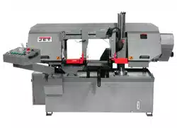
5. Slightly loosen screws (A and B, Figure 8-3).
6. Loosen inner screw (C
1
).
Figure 7-1: blade tension and tracking
While performing the
following, keep blade from rubbing
excessively on wheel shoulder, which can
damage wheel and/or blade.
7. Start saw blade, and slowly turn outer screw
(C
2
) to tilt idler wheel. Turn screw out so that
blade starts to move away from wheel shoulder;
then immediately turn screw in so that blade
moves slowly back toward shoulder.
8. Turn off saw blade.
9. Hold outer screw (C
2
) with a wrench and tighten
center screw (C
1
). Make sure outer screw does
not move while tightening inner screw.
10. Tighten screws A and B.
11. Close blade wheel covers and secure with
knobs.
12. Follow blade break-in procedures, sect. 7.4.
7.4 Blade break-in
A new blade should be “broken in” before normal,
extended use. Failure to break in a new blade will
shorten the service life of the blade, and result in
inefficient cutting performance.
1. Reduce blade speed to 1/2 of normal setting.
2. Set feed rate at 2 to 3 times longer than normal.
3. Make 5 complete cuts at the above settings,
through a cylindrical workpiece of about 8-inch
diameter. Listen for unusual noises or metallic
sounds.
4. If no unusual sounds or other issues are
detected, then the blade is ready for normal
operations.
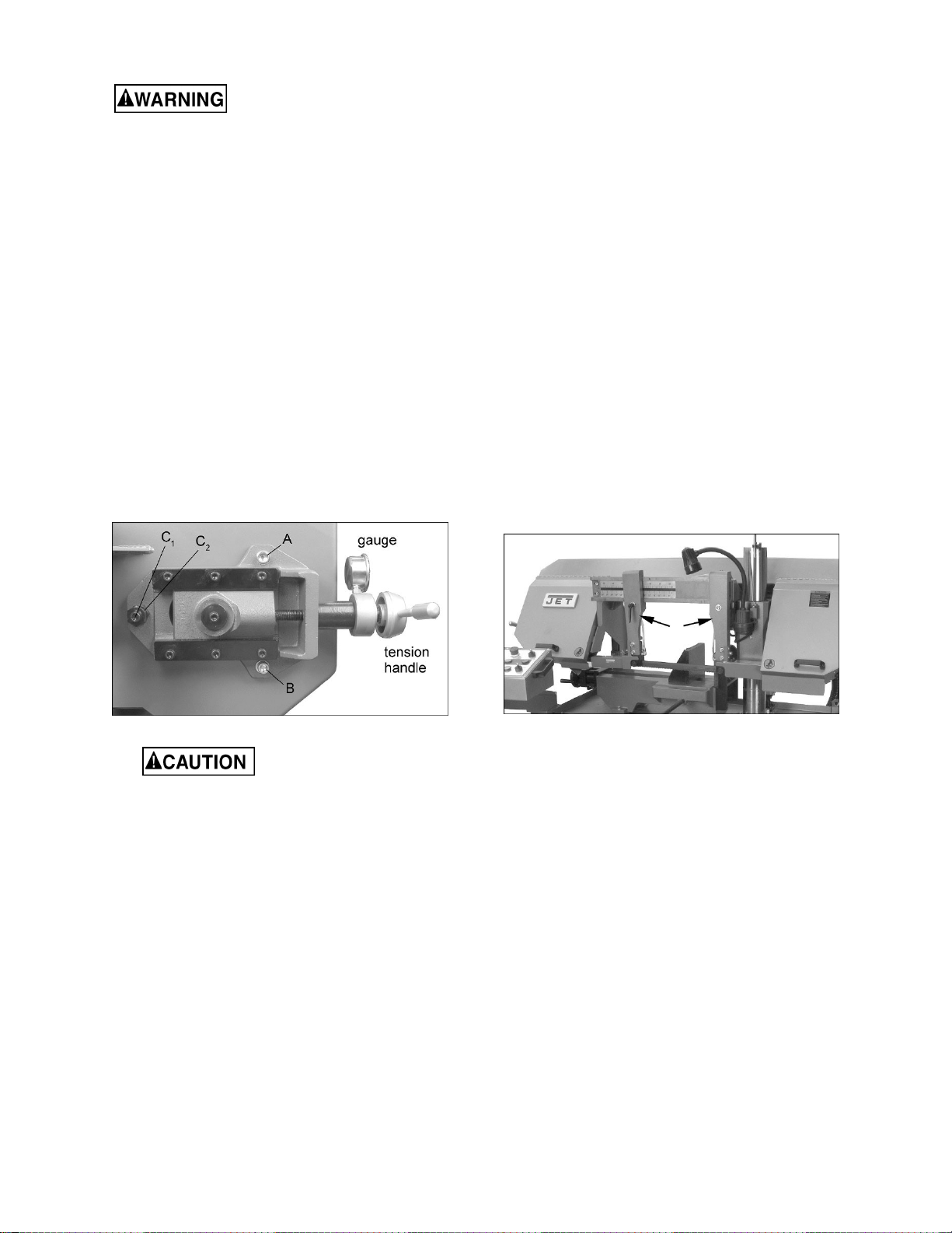
7.5 Support arm adjustment
The blade guide support arms (Figure 7-2) should
be set as close to vise jaw as possible, without
causing obstruction. The right arm has minimal
adjustment and is set by the manufacturer to clear
the fixed vise jaw. The left arm can be moved to
accommodate position of floating vise jaw. Loosen
handle and slide arm into position, then retighten
handle.
Figure 7-2
7.6 Blade guide bearing adjustment
Proper adjustment of blade guide bearings is critical
to efficient operation of the saw. The blade guide
bearings have been adjusted by the manufacturer.
They should rarely require adjustment except after
a blade change. Failure to maintain proper blade
adjustment may cause serious blade damage or
inaccurate cuts.
It is always better to try a new blade when cutting
performance is poor. If performance remains poor
after changing the blade, make the necessary
adjustments.
If a new blade does not correct the problem, check
the blade guides for proper spacing. For most
efficient operation and maximum accuracy, provide
only very slight clearance between blade and guide
bearings. The bearings will still turn freely with this
clearance. If the clearance is incorrect, the blade
may track off the drive wheel.
Loading ...
Loading ...
Loading ...