Loading ...
Loading ...
Loading ...
10
Check blade to make sure
welded section is same thickness as rest of
blade. If blade is thicker at weld, the guide
bearings may be damaged.
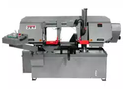
If required, adjust guide bearings as follows:
1. Disconnect machine from power source.
2. Two bearing guide assemblies are used in each
set of blade guides. The bearings are mounted
to eccentric shafts making them adjustable.
3. Loosen hex nut (A, Figure 7-3) while holding the
flats of the shaft (B) with a wrench.
4. Position the bearing by turning the shaft. Set the
bearing in light contact with blade.
5. Hold the shaft flats stationary while retightening
the hex nut.
6. Use knurled knob (C) to tighten carbide guides
(D) against blade. Do not overtighten.
7. The back edge of the blade runs against an
upper guide (E). This guide is fixed.
Figure 7-3: blade guides
7.7 Changing blade speed
Turn speed adjuster knob only
when blade is running. Failure to comply may
cause damage to machine.
Figure 7-4: blade speed adjustment
1. Raise blade approximately six inches above
workpiece and turn feed rate knob to zero.
2. Turn power on, and turn speed adjuster knob
(Figure 8-6) to match appropriate material. Turn
counterclockwise to increase speed, clockwise
to decrease.
3. The indicator on the mechanism shows speeds
in graduations of 93, 115, 165, 200, 260, 295
FPM. The graduations may not match the
recommended feed rate; an approximate speed
may therefore be required. For example, to set
a speed rate of 230 feet per minute, the
indicator would be set about midway between
200 and 260 FPM.
4. Sect. 11.0 shows recommended speeds for
basic materials. Refer to a machinist’s
handbook for more detailed recommendations.
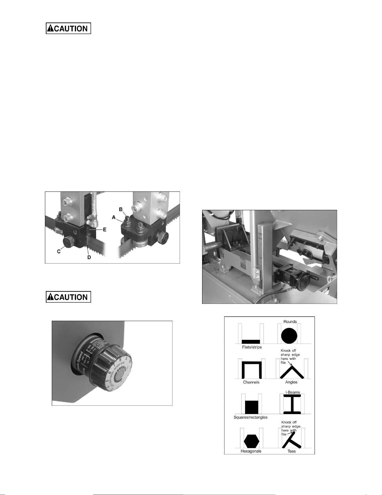
7.8 Vise adjustment
1. Place workpiece between vise jaws with
required amount to be cut-off extending out past
blade. (Figure 7-6 shows recommended
positioning of various workpiece shapes within
the vise.)
2. Rotate handwheel to move jaw close to
workpiece.
3. Press CLOSE VISE button to tighten jaw
against workpiece.
4. Press OPEN VISE button to release workpiece
after cut. Use handwheel to retract vise further.
Figure 7-5: vise adjustment
Figure 7-6
Loading ...
Loading ...
Loading ...