Loading ...
Loading ...
Loading ...
4
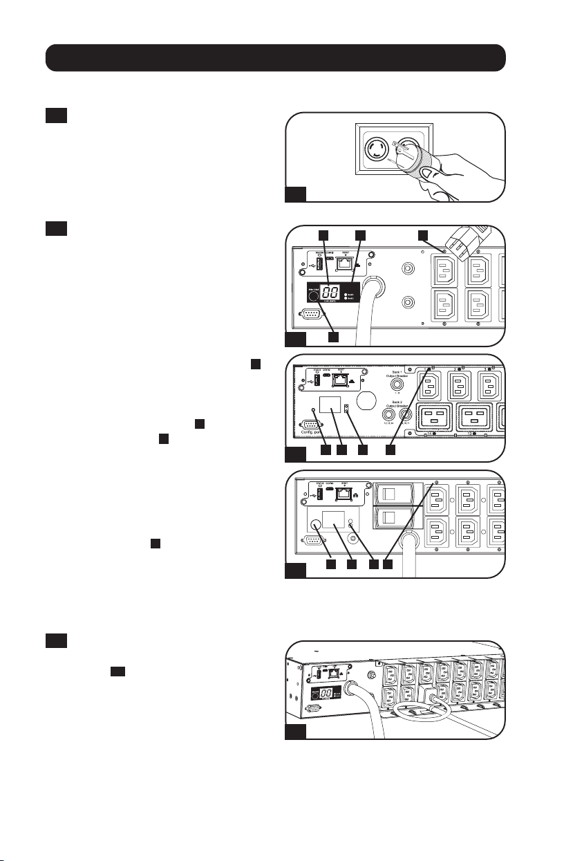
Connecting the PDU
2-1
Plug the PDU into a Compatible
Electrical Outlet: (120V L5-30R for
Model PDUMH30NET; 208/230V
L6-30R for Models
PDUMH30HVNET &
PDUMH30HV19NET; IEC 309 2P +
E for Model PDUMH32HVNET).
2-2
Connect Equipment to the PDU's
Output Receptacles: Plug
equipment into the NEMA
5-15/20R (Model PDUMH30NET),
IEC 60320 C13 (Models
PDUMH30HVNET &
PDUMH32HVNET) or IEC 60320
C13 & C19 (Model
PDUMH30HV19NET) output
receptacles of the PDU. The LED
A
near each output receptacle will
illuminate when the receptacle is
ready to distribute live AC power.
The digital load meter
B
may be set
with the switch
C
to display in
amps the PDU's total connected
load (all outlets), or the load carried
by either the upper or lower bank of
outlet receptacles. When the total
connected load display is selected,
both of the green LEDs to the right
of the display
D
will illuminate.
When the top bank display is
selected, only the top LED will
illuminate; when the bottom bank
display is selected, only the bottom
LED will illuminate.
2-3
Cord Retention (Optional): If you
attached the cord retention shelves
(STEP
1-3
), use them to secure
equipment power cords. Attach
each cord to the retention shelf by
looping the cord and securing it to
an attachment point with one of the
included cable ties. Make sure that
each equipment power cord can be
unplugged from the PDU without
removing the cable tie.
Installation
2-3
2-1
2-2
2-2
2-2
Your model may vary.
DB A
C
BC D A
C B D A
Loading ...
Loading ...
Loading ...