Loading ...
Loading ...
Loading ...
10
HARDWARE FEATURES
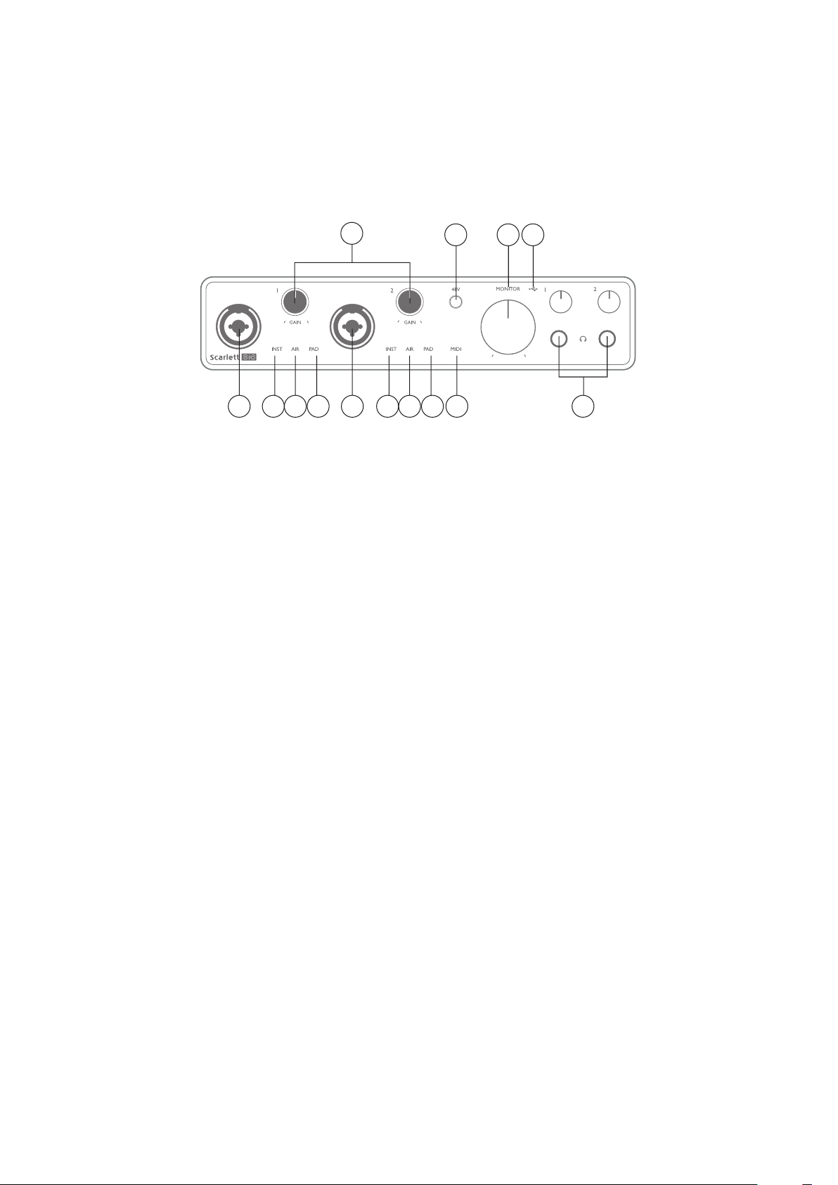
Front Panel
3
1 154 6 5 8 104 6
2 79
The front panel includes input connectors for Mic, Line and Instrument signals, the input gain and
monitoring controls, and headphones sockets.
1. Inputs 1 & 2 – “Combo” type input sockets - connect microphones, instruments (e.g.,
guitar), or line level signals here. Combo sockets accept both XLR and ¼” (6.35 mm) jacks.
Microphones will normally be connected using XLR plugs: instruments and line level signals
should be connected via ¼” (6.35 mm) jack plugs of either TR or TRS type. The preamp gain is
appropriate for microphones when an XLR plug is inserted, and for higher level signals when
a jack plug is inserted. Do not connect anything other than a microphone - e.g., the output
of a sound module or FX unit - via an XLR plug, as the signal level will overload the preamp,
resulting in distortion; also, if phantom power is enabled, the equipment may be damaged.
2. 48V – press to enable 48 V phantom power at the XLR contacts (mic inputs) of the Combo
connectors. The 48V indicator illuminates red when phantom power is selected.
3. GAIN 1 and GAIN 2 - adjust the input gain for the signals at Inputs 1 and 2 respectively. The
gain controls have concentric tri-colour LED ‘rings’ to confirm signal level: green indicates
an input level of at least -24 dBFS (i.e., ‘signal present’), the ring then turns amber at -6 dBFS
to indicate that the signal is close to clipping, and finally to red at 0 dBFS (digital clipping).
4. INST – the input configuration for the jack contacts at Inputs 1 and 2 can be selected in
software from Focusrite Control. The red LEDs illuminate when INST is selected. With INST
selected, the gain range and input impedance are altered (relative to LINE), and the input is
made unbalanced. This optimises it for the direct connection of instruments (usually via a
2-pole (TS) jack plug). When INST is off, the inputs are suitable for the connection of line level
signals. Line level signals may be connected either in balanced form via a 3-pole (TRS) jack
or unbalanced, via a 2-pole (TS) jack.
5. AIR – two yellow LEDs indicating selection of AIR mode for Inputs 1 and 2. AIR mode, selected
from Focusrite Control, modifies the frequency response of the input stage to model the
classic, transformer-based Focusrite ISA microphone preamps.
6. PAD – two green LEDs; illuminate when PAD is selected from Focusrite Control for Inputs 1
and 2. PAD decreases the signal level going to your DAW by 10 dB; use when the input source
has a particularly high level.
Loading ...
Loading ...
Loading ...